

Page 1
INSTRUCTION MANUAL
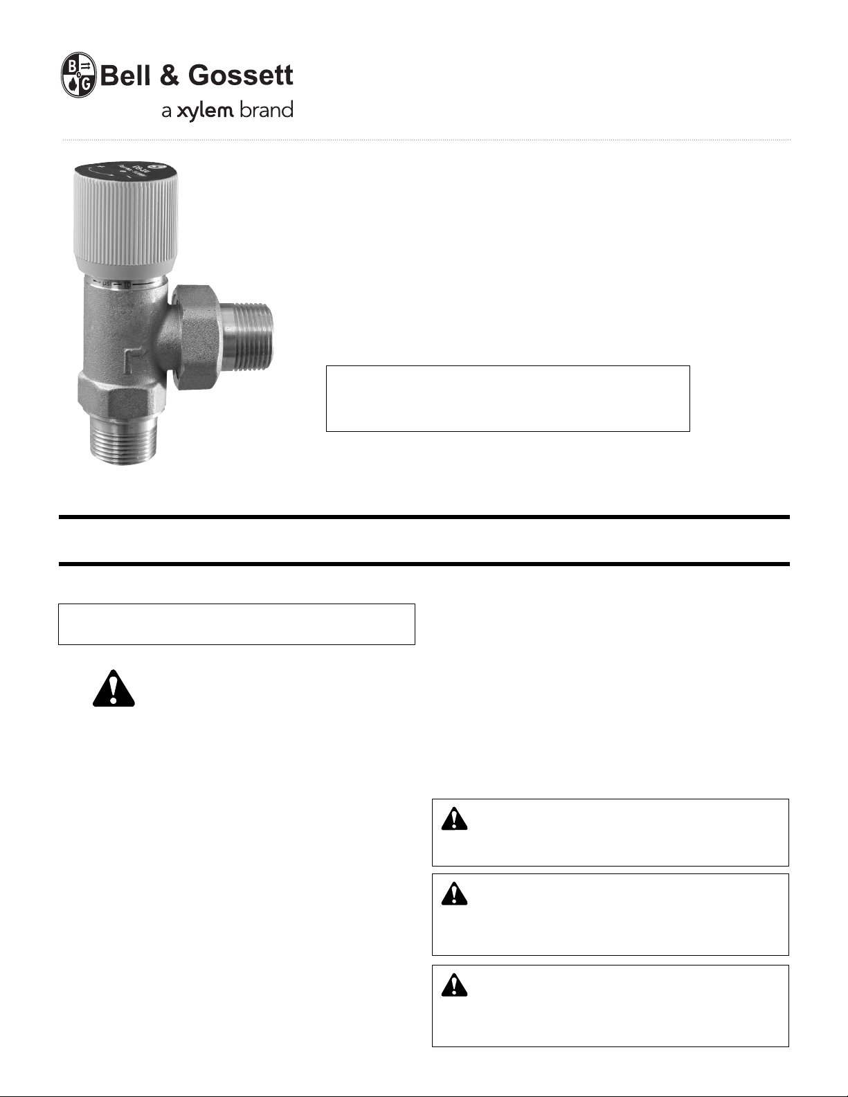
A91590B
DB-3/4"
Differential By-Pass Valve
3/4" x 3/4" NPT Male Connections
Operational Limits
Max. Temperature 230°F (110°C)
Max. Pressure 150psig (10 Bar)
INSTALLER: PLEASE LEAVE THIS MANUAL FOR THE OWNER’S USE.
NOTE: This product is not intended for use in potable
water applications.
SAFETY
INSTRUCTIONS
This safety alert symbol will be used in this manual to draw
attention to safety related instructions. When used, the safety
alert symbol means ATTENT ION! BECOME ALERT! YOUR
SAFETY IS I N V O LV E D ! FAI L U RE TO F O L L O W T HESE
INSTRUCTIONS MAY RESULT IN A SAFETY HAZARD.
DESCRIPTION
The Bell & Gossett DB differential by-pass valve is used in
systems where various heating loads may be simultaneousl
excluded from the circuit because of the closing of control or
zone valves.
It ensures a recirculation proportional to the number of valves
which close, avoiding noises and maintaining the head of the
pump at a constant value.
TECHNICAL SPECIFICATIONS
Connections: 3/4" x 3/4" NPT Male
Materials: – Body Brass
Medium: Water and glycol solutions up to 50%
Maximum Workin
Maximum Working Temperature: 230°F (110°C)
Maximum Flow Rate: 9 GPM
Adjustment Range: 2 to 10 PSI (0.15 to 0.7 Bar)
– Seals EPDM
– Spring Stainless Steel
– Knob ABS
g Pressure: 150 PSI (10 Bar)
INSTALLATION INSTRUCTIONS
CAUTION: All work must be performed by qualified
personnel trained in the proper application, installation,
and maintenance of systems in accordance with all applica-
y
ble codes and ordinances.
WARNING: System fluids are under pressure or temp-
erature can be hazardous. Be sure the pressure has
been reduced to zero and the system temperature is below
100°F (38°C). Failure to follow these instructions could result
in property damage and/or personal injury.
WARNING: State of California Residents
This product contains a chemical known by the State
of Califor nia to cause cancer. This products contains a
chemical known by the State of California to cause birth
defects or other reproductive harm.
Page 2
INSTALLATION INSTRUCTIONS (cont'd) INSTALLATION INSTRUCTIONS (cont'd)
CAUTION: Overtightening and breakage can occur
with the use of PTFE pipe joint compounds. PTFE
provides lubricity so that care must be exercised not to over
tighten joints. Failure to follow these instructions could result
in property damage and/or moderate personal injury.
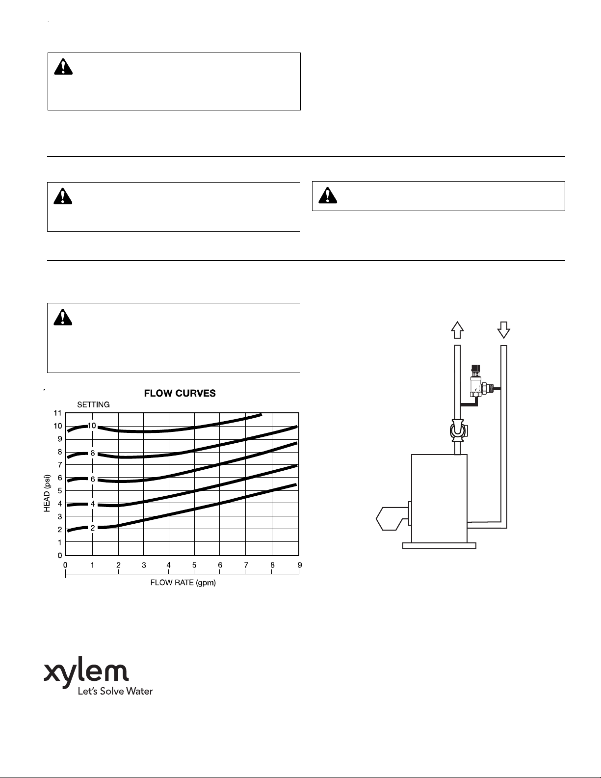
The by-pass valve should be installed after the pump between
the supply and return piping. It can be installed either in the horizontal or vertical position provided it is in accordance with the
direction of flow as indicated by the arrow on the valve body
(see Figure 1). With all valves open, set the bypass valve to
maximum pressure
(clockwise). Gradually open the bypass
valve (counterclockwise) until flow begins in the bypass valve.
Increase the pressure setting by 1/2 to 1 psi or turn knob clockwise 1/2 revolution so the water stops flowing through the
bypass valve.
OPERATING INSTRUCTIONS OPERATING INSTRUCTIONS
CAUTION: If the by-pass valve is not installed, com-
missioned and maintained properly, according to the
instructions contained in this manual, it may not operate correctly and may endanger the user.
SERVICE INSTRUCTIONS
There is no service required for the differential by-pass valve.
CAUTION: Corrosion or leakage of the differential by-
pass valve can cause damage or injury, Periodically
inspect the differential by-pass valve for signs of leakage or
corrosion. If noted, the differential by-pass valve must be
replaced. Failure to follow these instructions could result in
property damage and/or moderate personal injury.
CAUTION: Make sure that all the connecting pipework
is water tight.
Turn the knob to the desired value of the graduated scale; the
values correspond to the discharge pressure of the pump.
Lock
the setscrew located on the knob.
Xylem Inc.
8200 N. Austin Avenue
Morton Grove, Illinois 60053
Phone: (847) 966-3700
Fax: (847) 965-8379
www.xyleminc.com/brands/bellgossett
Bell & Gossett is a trademark of Xylem Inc. or one of its subsidiaries.
© 2012 Xylem Inc. A91590B October 2012
TYPICAL INSTALLATION
FIGURE 1
 Loading...