

Page 1
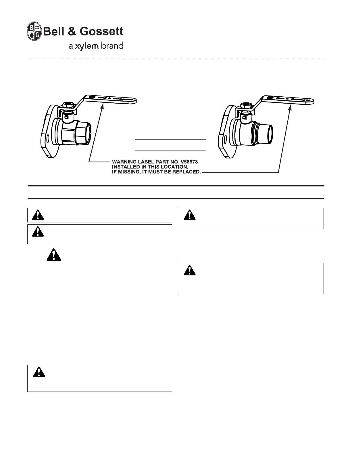
NPT
CONNECTION
INSTRUCTION MANUAL
Isolation
Flange
Operational Limits
Max Temperature 200°F (93°C)
Max Pressure 150psig (10 Bar)
INSTALLER: PLEASE LEAVE THIS MANUAL FOR THE OWNER’S USE.
SWEAT
CONNECTION
A07257B
WARNING: Wetted surface contains not more than 0.25%
of lead by weight.
WARNING: California Proposition 65 Warning! This product
contains chemicals known to the State of California to cause
cancer and birth defects or other reproductive harm.
SAFETY
INSTRUCTION
This safety alert symbol will be used in this manual to draw attention to
safety related instructions. When used, the safety alert symbol means
ATTENTION! BECOME ALERT! YOUR SAFETY IS INVOLVED! FAILURE TO FOLLOW THESE INSTRUCTIONS MAY RESULT IN A
SAFETY HAZARD.
DESCRIPTION
The Isolation Flange (IF) is a combination of an isolation valve and a
companion flange for circulators. The isolation flange allows easy service or replacement of the circulator without the need to drain the system.
INSTALLATION INSTRUCTIONS
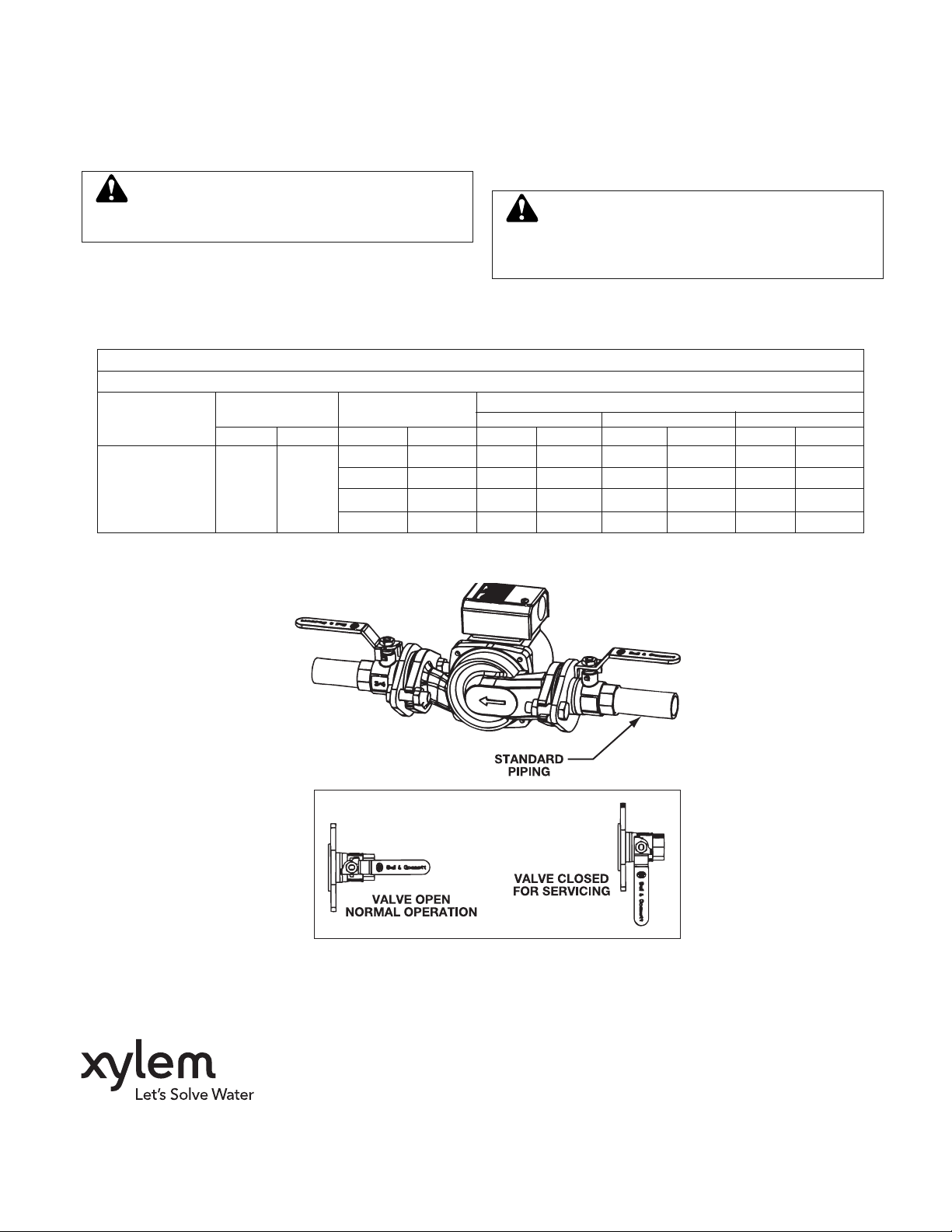
1. Install one IF on the suction side of the hydronic circulator and one on
the discharge side.
2. See the following installation instructions and drawings for additional
information.
WARNING: System fluids under temperature or pressure
can be hazardous. Be sure the pressure is relieved and
system temperature is below 100°F (38°C). Failure to follow these instructions could result in property damage and/or personal injury.
3. Apply torque in even increments to both flange bolts. Refer to the
pump manufacturers instruction manual for torque value. Both the
suction and discharge flanges must be torqued in this manner.
WARNING: To prevent leakage, make certain that the flange
bolts have been adequately torqued. Failure to follow these
instructions could result in personal injury and/or property damage.
For NPT connections:
a) Apply pipe compound conservatively to the male connecting fittings
only.
b) Upon completion of IF installation to piping, check connections for
leaks.
CAUTION: Over-tightening and breakage can occur with the
use of teflon pipe joint compounds. Teflon provides lubricity
so that care must be exercised not to over-tighten joints. Failure
to follow these instructions could result in property damage and/or
personal injury.
For Sweat Connections:
a) For soldering, use 95-5 (Tin-Antimony) solder and a good grade of
flux. Solder end v
bly. Refer to table 1 for solder types and temperatures. Solder joint
strength and working pressure varies with tube size, solder grade
and temperature as defined in ASME B16.18 and B16.22. Do not
exceed the limits stated in table 1.
b) Cut the tube square and deburr both ID and OD. Do not deform the
tube, otherwise it must be re-sized. Clean tube end and valve solder
cup with abrasive cloth or wire brush until the surfaces are bright
metal. Alternatively use an approved cleaning paste: in this case
spread the paste evenly on the tube; insert the tube into the cup and
turn to distribute the paste; finally remove the excess paste.
c) When sweating joints, first wrap the valve body with a cool wet rag,
then direct the flame with care to avoid subjecting the valve to ex cessive heat. Allow the valve to cool before touching or operating.
The valve must be in the fully closed position during soldering. Valve
seats may be damaged if soldering is done in the open or partly open
position.
alves are suitable for soldering without disassem-
Page 2
d) While soldering, it is important to use a properly sized torch with a
sharp pointed flame so that the solder end is heated fully and quickly.
Apply heat so that the flame is directed on the cup area but away
from the valve body. Although soft 50/50 solder is easier to use,
these valves can also be successfully soldered with 95-5, however
caution must be used to prevent damage (see table 1.) Cool the
valve body before soldering the second end.
e) Check the soldered connections for leaks.
CAUTION: Heat associated with the use of silver solder may
damage valve and void the warranty. Do not use silver solder. Failure to follow these instructions could result in property damage and/or moderate personal injury.
IMPORTANT: Relieve pressure from the circulator by slowly loosening
the bolts allowing the water to slowly drain from the pump body. Refer
to the circulator instruction manual when reinstalling a circulator. After
a pump is reinstalled, turn the handle of both isolation valves counterclockwise 90° to open the valves for normal operation.
SERVICE INSTRUCTION
There is no service required for the Isolation flange.
CAUTION: Corrosion or leakage of the IF valve can cause
damage or injury. Periodically inspect the IF valve for signs
of leakage or corrosion. If corrosion or leakage is noted, the IF valve
must be replaced. Failure to follow these instructions could result in
property damage and/or moderate personal injury.
OPERATING INSTRUCTIONS
To isolate the circulator from the system, turn the handle of both isolation valves clockwise 90° to close the valve. Remove circulator for
repair/replacement.
TABLE 1
Pressure – Temperature Ratings
Melting Range Working Temperature
Joining
Material
95-tin-antimony
solder
ASTM B32 alloy
grade 95TA
Note: Above stated limits are not imposed by the valve, but by the strength of the soldering joint according to ASME B16.22.
*Soldered copper tube joints have been tested at 230 psi (1600 kPa) in accordance with ISO 2016.
Degrees Degrees
°F °C °F °C psi kPa psi kPa psi kPa
0/+100 -18/+38 500* 3500* 400* 2800* 300* 2100*
450/464 230/240
0/+150 -18/+66 400* 2800* 350* 2400* 275* 2000*
0/+200 -18/+93 300* 2100* 250* 1700* 200 1400
0/+250 -18/+121 200 1400 175 1200 150 1050
Size 1⁄8" – 1" Size 11⁄4" – 2" Size 21⁄2" – 4"
Maximum Working Gauge Pressure
Xylem Inc.
8200 N. Austin Avenue
Morton Grove, Illinois 60053
Phone: (847) 966-3700
Fax: (847) 965-8379
www.xyleminc.com/brands/bellgossett
Bell & Gossett is a trademark of Xylem Inc. or one of its subsidiaries.
© 2012 Xylem Inc. A07257B May 2012
 Loading...