

Page 1
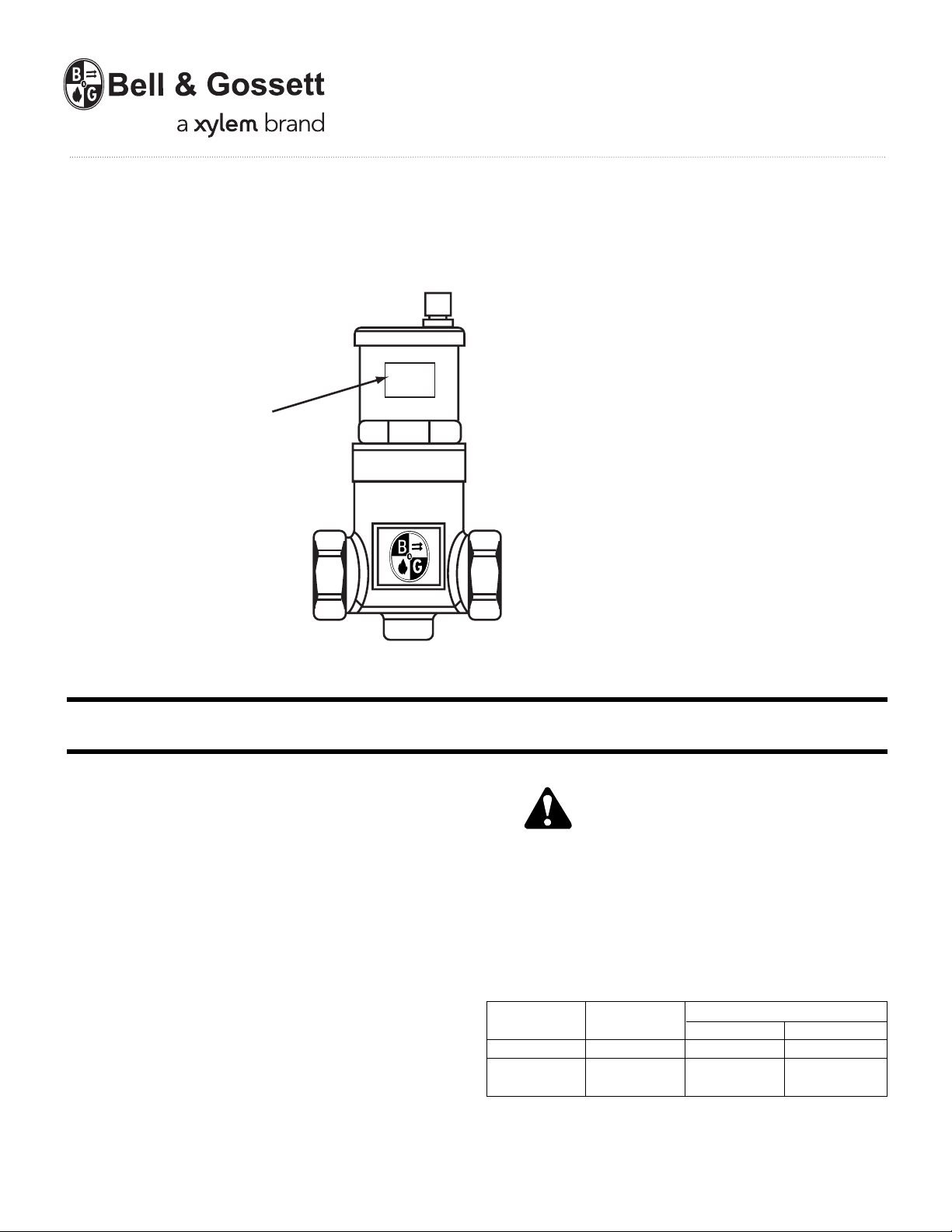
Warning label V56871
installed in this location.
If missing, it must be
replaced.
INSTRUCTION MANUAL
A07180C
Enhanced
Air Separator
INSTALLER: PLEASE LEAVE THIS MANUAL FOR THE OWNER’S USE.
DESCRIPTION
The Bell & Gossett Model EASB-JR Enhanced Air Separator
automatically removes entrained air bubbles in hydronic systems.
As fluid enters the EASB-JR, the velocity is slowed down creating a low pressure area. The air bubbles are then released from
fluid and collect on the coalescing medium. As the bubbles
coalesce, they will rise to the top of the air separator where they
can be released to atmosphere through the built-in automatic
air vent. The air separator has a bottom
accommodate a B&G diaphragm expansion tank. The compact
design and brass body construction make the EASB-JR ideal
for residential and commercial hydronic heating systems.
TECHNICAL SPECIFICATIONS
Available Sizes:
3
/4" NPT
1" NPT 1" Sweat
1
1
/4" NPT 11/4" Sweat
1
1
/2" NPT
2" NPT
Materials:
Body . . . . . . . . . . . . . . . . . . . . . . . .Brass
Coalescing Medium . . . . .Stainless Steel
1
/2" NPT connection to
3
/4" Sweat
Model EASB-JR
SAFETY
INSTRUCTIONS
This safety alert symbol will be used in this manual to draw
attention to safety related instructions. When used, the safety
alert symbol means ATTENTION! BECOME ALERT! YOUR
SAFETY IS INVOLVED! FAILURE TO FOLLOW THE INSTRUCTIONS MAY RESULT IN A SAFETY HAZARD.
Chart A
Working Pressure & Temperature Limits
(Solder Type Limits Per ASTM Std. B16.18-1979)
FLOW-CONTROL TYPE OF
STYLE SOLDER PRESSURE PSI TEMPERATURE °F
NPT – 150 250
SWEAT
95-5
Tin-Antimony
MAXIMUM LIMITATIONS
150 250
Page 2
INSTALLATION INSTRUCTIONS
Enhanced Air Separators with Sweat Connections
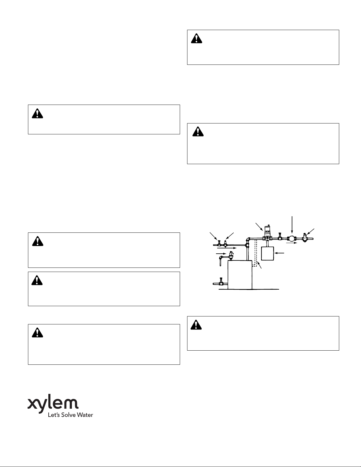
1. Install the air separator in horizontal piping so that the air
vent is in the top vertical position. The air separator is
bi-directional so that water can flow in either direction
(see Figure 1).
2. Use a torch with a sharp pointed flame.
3. Clean tube ends and air separator connection thoroughly.
4. Use 95-5 (Tin-Antimony) solder and a good grade of flux.
CAUTION: Heat associated with the use of silver solder
may damage a Air Separator voiding the warranty. Do
not use silver solder. Failure to follow these instructions could
result in proper damage and/or moderate personal injury.
5. When sweating joints, first wrap the air separator with a cool
wet rag, then direct the flame with care to avoid subjecting
the EASB-JR to excessive heat.
6. Refer to Chart A for the maximum operating pressure and
temperature based on the type of solder used.
7. After sweating the joints, check the connections for leakage.
Enhanced Air Separators with NPT Connections
1. Install the air separator in horizontal piping so that the air
vent is in the top vertical position. The use of Teflon tape
sealer or a high quality thread sealant is recommended. The
air separator is bi-directional so that water can flow in either
direction (see Figure 1).
2. Check connections for leaks.
CAUTION: The use of Teflon®impregnated pipe com-
pound and Teflon tape on pipe threads provides lubricity
which can lead to overtightening and breakage. Do not overtighten. Failure to follow this instruction can result in moderate personal injury from hot water and/or property damage.
WARNING: State of California Residents
This product contains a chemical known by the State
of California to cause cancer. This product contains a chemical known by the State of California to cause birth defects or
other reproductive harm.
CAUTION: Hot venting can be hazardous. Avoid con-
tact with venting fluid and only manually vent when
system temperature is below 100°F (38°C). Failure to follow
these instructions could result in property damage and/or
personal injury.
Turn the cap on top of the vent counterclockwise one full turn to
allow the EASB-JR to automatically remove the air from the
system. This is the normal operating position.
To shut down the automatic air vent, turn the cap tight. Be sure
to turn the cap back to the open position (one full turn) for
normal operation.
SERVICE INSTRUCTIONS
WARNING: Servicing the Enhanced Air Separator with
unit pressurized or at temperatures above 100°F
(37.8°C) can cause personal injury. Make sure pressure is
removed from unit and temperature is below 100°F (37.8°C).
Failure to follow these instructions could result in serious
personal injury or death and property damage.
The Enhanced Air Separator should not require servicing. If the
system fluid contains large amounts of contaminants, the
perforated metal strainer may become contaminated with
foreign substances. The Enhanced Air Separator cap unscrews
from the body for easy cleaning of strainer.
B&G BOOSTER
FLO-CONTROL
VALVE
TO
SYSTEM
DIAPHRAGM TYPE
EXPANSION TANK
SHUT-OFF
VALVE
CW FILL
B&G RELIEF
VALVE
RETURN
EASB-JR AIR
SEPARATOR
B&G PRESSURE
REDUCING VALVE
FLOW
BOILER
OPTIONAL SIDE
OUTLET BOILER
CONNECTION
TYPICAL INSTALLATION – FIGURE 1
OPERATING INSTRUCTIONS
CAUTION: Contaminants and scale from the system
can foul the automatic air vent operation mechanism.
Keep vent cap closed tight during the system filling to prevent contaminants from running into valve vent mechanism.
Failure to follow these instructions could result in property
damage and/or moderate personal injury.
Xylem Inc.
8200 N. Austin Avenue
Morton Grove, Illinois 60053
Phone: (847) 966-3700
Fax: (847) 965-8379
www.xyleminc.com/brands/bellgossett
Bell & Gossett is a trademark of Xylem Inc. or one of its subsidiaries.
© 2012 Xylem Inc. A07180C May 2012
CAUTION: Uncontrolled venting of water can occur
with automatic air vents if foreign material prevents
vents from closing. Unwanted flow should be directed to a
drain. Failure to follow these instructions could result in property damage and/or moderate personal injury.
 Loading...