

Page 1
INSTRUCTION MANUAL
Sediment Removal
Separator
Model SRS
A05767B
INSTALLER: PLEASE LEAVE THIS MANUAL FOR THE OWNER’S USE.
SAFETY
INSTRUCTION
This safety alert symbol will be used in this manual to draw
attention to safety related instructions. When used, the safety
alert symbol means ATTENTION! BECOME ALERT! YOUR
SAFETY IS INVOLVED! FAILURE TO FOLLOW THE
INSTRUCTION MAY RESULT IN A SAFETY HAZARD!
DESCRIPTION
The Bell & Gossett Model SRS Sediment Removal Separator
is recommended for both sediment and air removal in hydronic
systems. It is designed and constructed to the requirements
of the ASME Boiler & Pressure Vessel Code Section VIII Div.
1. It is an efficient separator utilizing centrifugal action to
remove system sediment.
TEMPERATURE AND PRESSURE LIMITS
Maximum Operating Temperature: 350°F
Maximum Operating Pressure: 125 psig
INSTALLATION INSTRUCTIONS
1. It is recommended that the SRS be installed in the system
main so that full system flow is directed through the SRS.
This permits fast elimination of sediment and solids that
may damage pump seals or other system components.
Bypass installations may be used but they will not be nearly
as effective in protecting system components.
WARNING: Lifting lugs supplied on top of SRS
are not strong enough to support the SRS full of
fluid. Do not use these lugs to support or hang the SRS
in the piping system. Failure to follow these instructions
could result in serious personal injury or death and
property damage.
2. SRS sizes through an SRS-8 can be supported in the piping system as long as pipe hangers are attached to the tangential nozzles as close to the SRS shell as possible. Sizes
larger than an SRS-8 will need to have additional supports
such as cradle under the SRS acting on a diameter as close
to the SRS outside diameter as possible or factory installed
clips welded to the shell for overhead hanging.
Page 2
WARNING: The SRS is an ASME Code Section
VIII Div. 1 designed and constructed pressure vessel.
Welding by uncertified welders will void the ASME certification and result in an unsafe condition. Failure to follow
these instructions could result in serious personal injury
or death and property damage.
3. The SRS needs to be mounted sufficiently high off the floor
to allow blow down piping to be attached.
4. The SRS should be located near a drain to facilitate the
removal of collected sediment. If an automated blowdown/
purge valve is used, air or electricity will have to be provided
to this location. For installation of blowdown components,
follow the instructions provided with this equipment.
IMPORTANT: Purge/blowdown valves selected must be
designed for sediment service or else clogging, seat wear or
damage will occur resulting in valve leakage.
5. If the air separation feature of the SRS is to be utilized an
automatic air vent, such as a Bell & Gossett 107A Air Vent,
must be installed in the SRS top connection. The SRS can
also be piped to a standard compression tank. Refer to Bell
& Gossett Instruction Manual S10300 for installation
instructions.
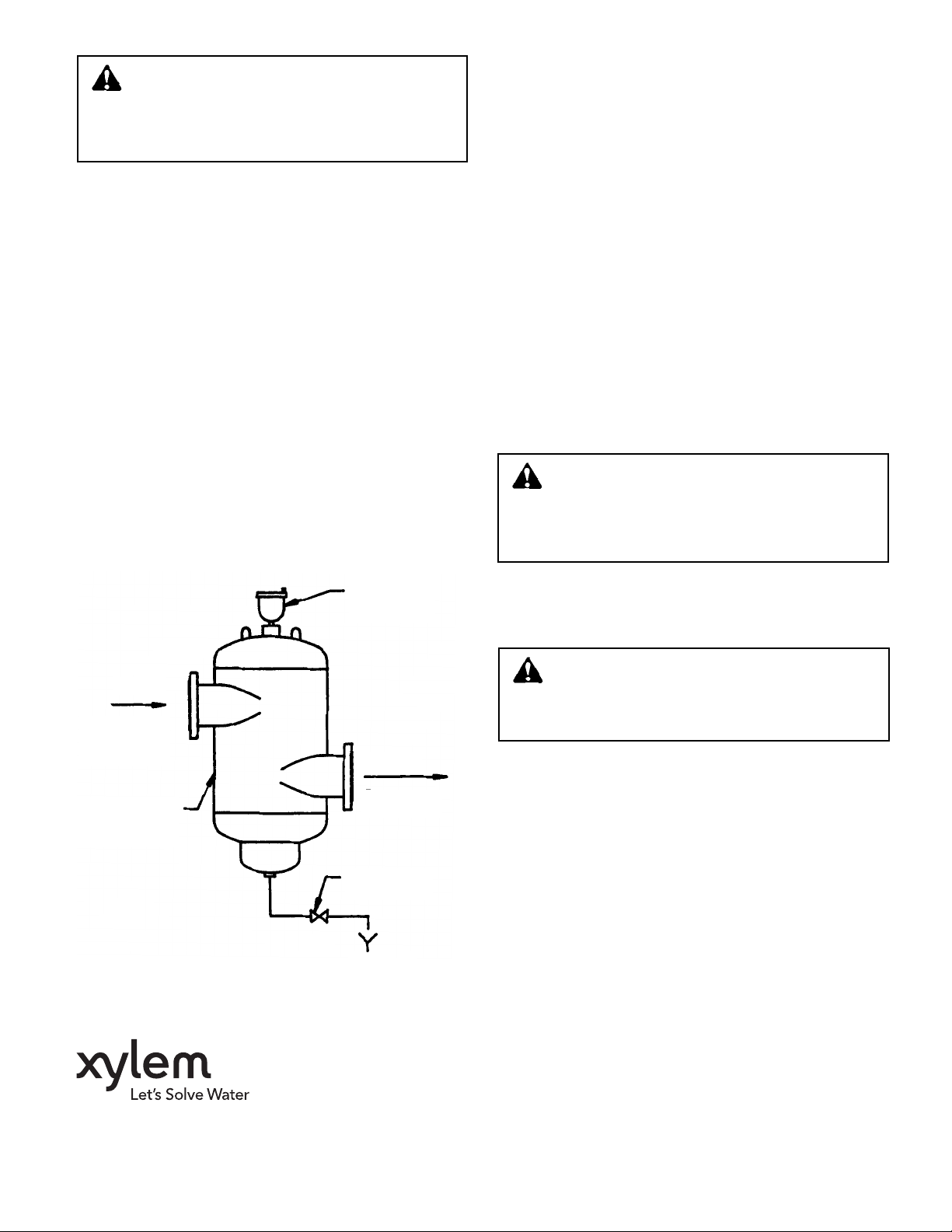
6.Figure 1 shows a typical installation with some of the
optional equipment that can be utilized with the SRS.
OPERATING INSTRUCTIONS
1. The SRS separates sediment from the system by centrifugal force. Heavier than water sediment particles are thrown
against the inner walls of the SRS and move down the walls
to the sump in the bottom of the SRS where it collects.
IMPORTANT: The SRS is designed only for the removal of
undissolved, inorganic, heavier than water sediment/solids
that enter through cooling towers, make-up water or via system installation. The SRS is not intended for removal of dissolved sediment or organic material like algae.
2.Collected sediment must be periodically blown down
(removed) from the 1" NPT sump connection on the bottom
of the SRS. If excessive amounts of sediment are allowed
to collect without being periodically removed, sediment will
start to pass through the SRS and not be removed. Purging
(blowdown) of the sump can be accomplished manually but
a much preferred method is by the the use of an automatic
valve and adjustable timer system. The timer cycle and the
length of time the purge (blowdown) valve is open will vary
depending on the amount of sediment in the system.
IMPORTANT: Failure to adequately purge the SRS may result
in a buildup of sediment in the sump which may clog and prevent discharge of sediment.
WARNING: The SRS is not designed for fresh
water service. Excessive corrosion of steel construction will occur. Do not use in systems with fresh water
being added unless corrosion inhibitors are present.
Failure to follow these instructions could result in serious
personal injury or death and property damage.
INLET
FROM BOILER
CHILLER OR
CONVERTER
B&G SEDIMENT
REMOVAL
SEPARATOR
AUTOMATIC
AIR VENT
107A
OUTLET
TO PUMP
SUCTION
BLOW DOWN
VALVE
SERVICE INSTRUCTIONS
1. The SRS must be inspected periodically for signs of corrosion. If corrosion exceeds .050" the SRS must be replaced.
WARNING: Excessive corrosion will cause the
SRS to leak or rupture. Periodic inspections must
be made to check for corrosion. Failure to follow these
instructions could result in serious personal injury or
death and property damage.
2. There are no moving parts or strainers in the SRS that require service.
3. Purge valves and associated equipment may require service. Refer to the instruction manuals supplied with these
devices for service requirements.
Xylem Inc.
8200 N. Austin Avenue
Morton Grove, Illinois 60053
Phone: (847) 966-3700
Fax: (847) 965-8379
www.xyleminc.com/brands/bellgossett
Bell & Gossett is a trademark of Xylem Inc. or one of its subsidiaries.
© 2012 Xylem Inc. A05767B May 2012
 Loading...