

Page 1
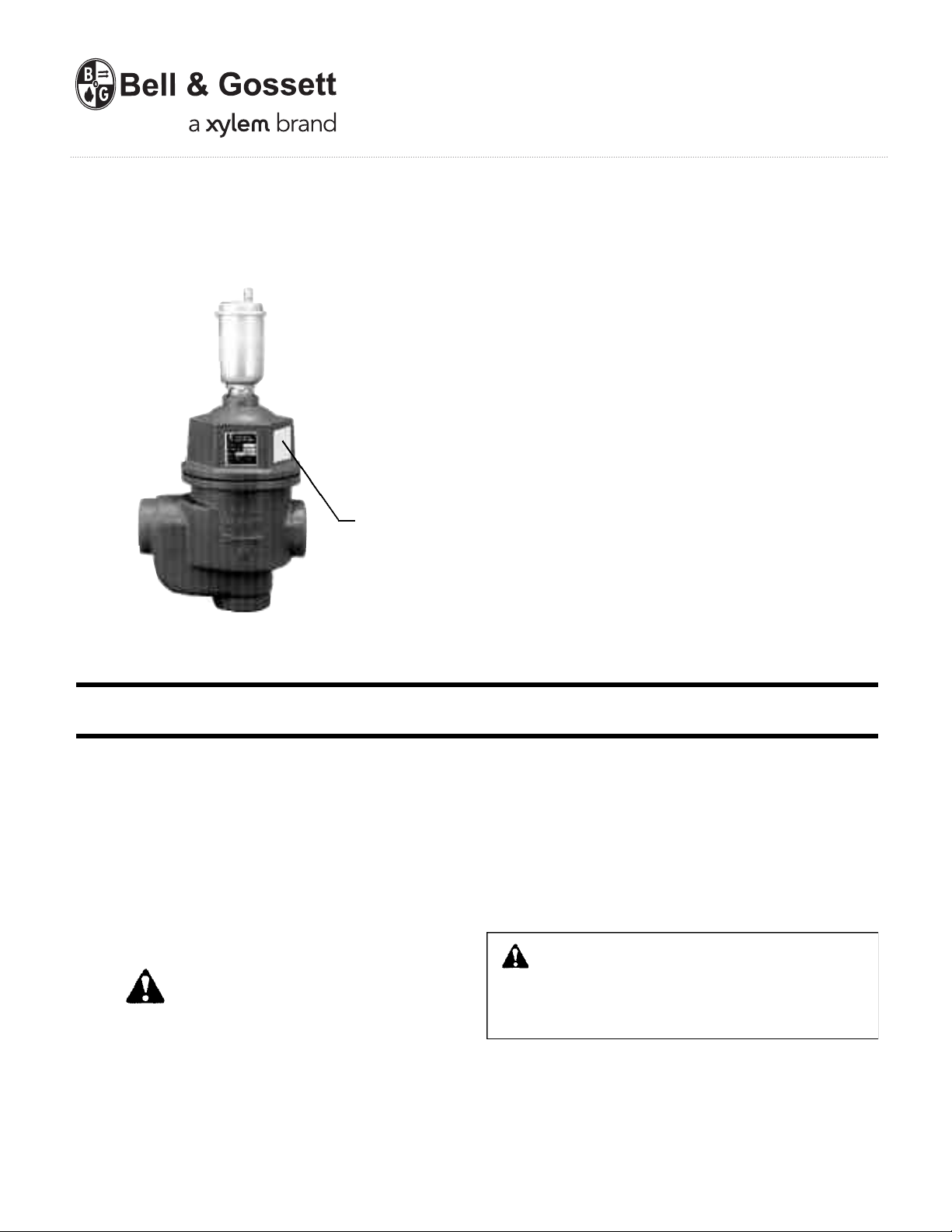
Enhanced Air
Separator
Model EAS
WARNING LABEL PART NO. V56871
INSTALLED IN THIS LOCATION.
IF MISSING, IT MUST BE REPLACED.
INSTRUCTION MANUAL
A03852C
INSTALLER: PLEASE LEAVE THIS MANUAL FOR THE OWNER’S USE.
DESCRIPTION
The Bell & Gossett Model EAS Enhanced Air Separator is a
highly efficient device for removing entrained air bubbles in
hydronic systems. The combination diffuser and coalescing
medium design makes possible the removal of very small air
bubbles from the fluid stream by coalescence at substantial
fluid velocity. The diffuser forces the system fluid to cover the
entire inlet portion of the coalescing medium. The coalescing
medium will collect air bubbles on its stainless steel filaments.
As the bubbles coalesce together, they will rise to the top of
the separator where they can be released to the atmosphere
through the automatic air vent.
SAFETY
INSTRUCTIONS
This safety alert symbol will be used in this manual to draw
attention to safety related instructions. When used, the safety
alert symbol means ATTENTION! BECOME ALERT! YOUR
SAFETY IS INVOLVED! FAILURE TO FOLLOW THES E I N STRUCTIONS MAY RESULT IN A SAFETY HAZARD.
Temperature and Pressure Limits
Maximum Operating Temperature: 250°F (121°C)
Maximum Operating Pressure: 150 psig (10.3 bar)
INSTALLATION INSTRUCTIONS
1. The Enhanced Air Separator Model EAS is supplied in
either 1", 1
bushed down to
2. The Enhanced Air Separator can be installed inline or in an
angle configuration to replace a piping elbow. The unit must
be installed with the automatic air vent in a vertical position.
3. Pipe the Enhanced Air Separator into the system as shown
in typical installation Figures 1 or 2.
lubricity which can lead to overtightening and breakage.
Do not overtighten. Failure to follow this instruction can
result in moderate personal injury from hot water and/or
property damage.
4. The Enhanced Air Separator must be installed with the flow
arrow on the body casting pointing in the direction of flow.
1
/4", 11/2" or 2" NPT sizes. The 1" size may be
3
/4" NPT for use in 3/4" piping systems.
CAUTION: The use of PTFE impregnated pipe compound and PTFE tape on pipe threads provides
Page 2

SHUT-OFF
VALVE
CW FILL
B&G RELIEF
VALVE
RETURN
B&G PRESSURE
REDUCING VALVE
FLOW
BOILER
TYPICAL INSTALLATION
B&G COMPRESSION TANK
TANK FITTING
C.W. FILL
B&G PRESSURE REDUCING VALVE
B&G RELIEF VALVE
ENHANCED AIR
SEPARATOR
OPTIONAL SIDE
OUTLET BOILER
CONNECTION
FIGURE 1
ENHANCED AIR SEPARATOR
B&G BOOSTER
DIAPHRAGM TYPE
EXPANSION TANK
PITCH UP TANKB&G AIRTROL
B&G TRIPLE
DUTY VALVE
TO
SYSTEM
TO
SYSTEM
The automatic air vent can be used to automatically or manually vent the hydronic stem. To manually operate the vent,
press down on the vent stem (tire type valve).
C A U T I O N: Hot venting water can be hazardous.
Avoid contact with venting fluid and only manually
vent when system temperature is below 100°F (37.8°C).
Failure to follow these instructions could result in property
damage and/or personal injury.
To shut off the vent so that it cannot vent automatically, (only
those without overflow connector installed), screw cap on top
of vent down tight. For normal automatic venting open cap
only about one full turn so that there is a slow release of air. A
fast release of air will allow contaminants or scale to foul the
vent mechanism. The small hole in the side of the cap allows
air to escape with cap in place. When an overflow connector
and tube to a safe drain is used, continuous automatic venting is provided.
SERVICE INSTRUCTIONS
W A R N I N G: Servicing the Enhanced Air Separator
with unit pressurized or at temperature above 100°F
(37.8°C) can cause personal injury. Make sure pressure is
removed from unit and temperature is below 100°F
(37.8°C). Failure to follow these instructions could result in
serious personal injury or death and property damage.
OPTIONAL
SIDE OUTLET
RETURN
BOILER CONNECTION
TYPICAL INSTALLATION
FIGURE 2
CAUTION: Uncontrolled venting of water can occur
with automatic air vents if foreign material prevents
vent from closing. A No. 113023 overflow connector and
1
/4" OD copper tube should be used to direct unwanted
flow to a drain. The 2" NPT size can be piped to a drain
using a flare to
1
/8" NPT connector with 1/4" OD copper
tube. Failure to follow these instructions could result in
property damage and/or moderate personal injury.
OPERATING INSTRUCTIONS
CAUTION: Contaminants and scale from the system
can foul the automatic air vent operating mechanism.
Keep vent cap closed tight during the system filling to prevent contaminants from running into valve vent mechanism. Failure to follow these instructions could result in
property damage and/or moderate personal injury.
1. The Enhanced Air Separator should not require servicing. If
the system fluid contains large amounts of contaminants,
the perforated metal diffuser and/or the air coalescing
brush may become contaminated with foreign substances.
The Enhanced Air Separator cap unscrews from the body
for easy cleaning of both the brush and diffuser. When replacing the perforated metal diffuser make sure that the
overlap portion of the diffuser is at 90° to the NPT body
connection. The diffuser will have to be held during the
assembly of body and cap to prevent it turning. This can be
done through the NPT connections. Please refer to Figure 3.
2. The #87 or #78 automatic air vent can be replaced by
unscrewing it from the Enhanced Air Separator cap.
AUTOMATIC
AIR VENT
CAP
BAFFLE
DIFFUSER
WIRE BRUSH
O-RING
BODY
FIGURE 3
C A U T I O N: Corrosion of or leakage from the En-
hanced Air Separator can cause damage or injury.
Periodically inspect the Enhanced Air Separator for signs
of leakage or corrosion. If noted the Enhanced Air Separator must be replaced. Failure to follow these instructions
could result in property damage and/or moderate personal
injury.
Xylem Inc.
8200 N. Austin Avenue
Morton Grove, Illinois 60053
Phone: (847) 966-3700
Fax: (847) 965-8379
www.xyleminc.com/brands/bellgossett
Bell & Gossett is a trademark of Xylem Inc. or one of its subsidiaries.
© 2013 Xylem Inc. A03852C October 2013
 Loading...