

Page 1
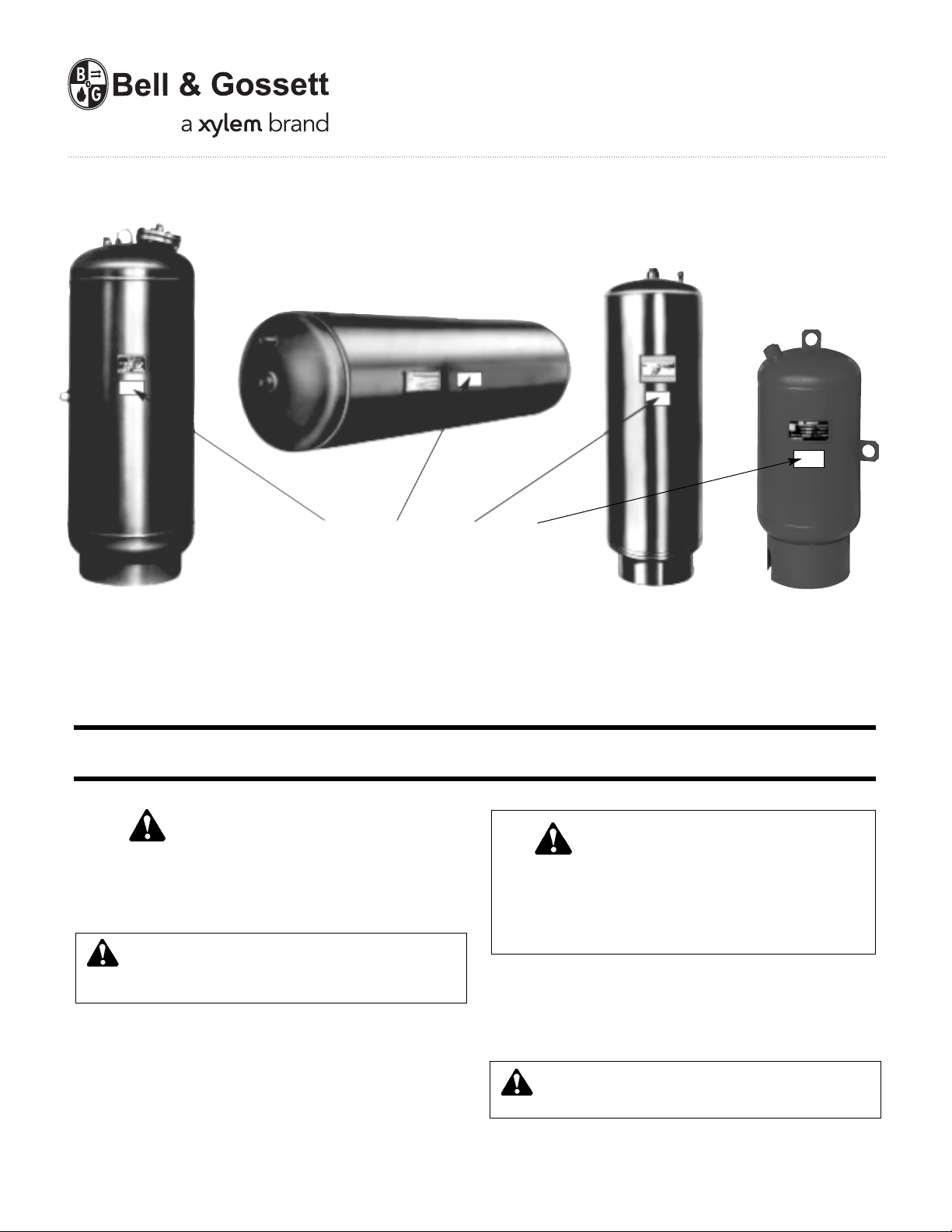
WARNING LABEL PART NO. 9015-463 INSTALLED IN THIS
LOCATION. IF MISSING, IT MUST BE REPLACED.
INSTRUCTION MANUAL
A01500I
Series "B"
Series "D"
Series "B-LA"
Pressurized Expansion Tanks (ASME)
INSTALLER: PLEASE LEAVE THIS MANUAL FOR THE OWNER’S USE.
SAFETY
INSTRUCTIONS
This safety alert symbol will be used in this manual to draw attention to
safety related instructions. When used, the safety alert symbol means
ATTENTION! BECOME ALERT! YOUR SAFETY IS INVOLVED!
FAILURE TO FOLLOW THESE INSTRUCTIONS MAY RESULT IN A
SAFETY HAZARD.
WARNING: Explosion Hazard
Failure to follow instructions in the accompanying product
manual can cause rupture or explosion, possibly causing serious or
fatal injury, leaking or flooding and/or property damage.
DESCRIPTION
Precharged Expansion Tanks contain either a bladder or a diaphragm
to separate the air charge from the system water. Tanks are designed
to absorb the expansion forces of heating/cooling system water while
maintaining proper system pressurization under varying operating
conditions.
DANGER: Series “B”, “D”, & “B-LA” are for use in closed loop
systems only. Domestic, potable or fresh water can cause serious
corrosion in a tank. This can result in leakage and a potential
explosion. Do not use for domestic, potable or fresh water. Failure
to follow this instruction will result in serious personal injury or
death and property damage.
OPERATIONAL LIMITS
Maximum Operating Pressure: 125 psi (or as stamped on nameplate)
Maximum Operating Temperature: 240ºF
Minimum Operating Temperature: 35°F (non-glycol application)
safe use and proper care of this product.
NOT FOR USE IN DOMESTIC
(POTABLE) WATER SYSTEMS
18°F (glycol application)
WARNING: Carefully read the Instruction Manual to avoid
serious personal injury and property hazards and to ensure
Page 2
2
POINT OF CONNECTION
A. General
The Series B and Series D tanks work equally well when installed in the
vertical or horizontal position. When Series B tank is installed horizontally,
the system connection must be located below the centerline of the tank.
The Series B-LA tanks must be installed in vertical position. They cannot
be installed in the horizontal position.
The pressurized expansion tank-to-system piping differs from the
“standard” compression tank piping in several major aspects:
1. Air from the system must be purged to the atmosphere and not allowed
to enter the tank.
2. Tank-to-system piping must not be pitched-up to the tank.
3. Shut-off and drain valves or tank purge valve B&G TPV must be
installed in the tank-to-system piping in order to properly check and
recharge the tank air after the system has been filled with water.
4. Airtrol Tank Fitting (ATF or ATFL) is not required.
B. Piping
Typical tank-to-system and air vent piping are illustrated by Figures 1 thru
6. Some general notes regarding this piping are listed below:
1. The connection point from tank-to-system represents the point of no
pressure change. This means that the expansion tank must be
connected as close as possible to the suction side of the system
circulating pump for proper system operation.
2. The branch piping to the tank must be attached to the main to minimize
the possibility of air and debris entering the tank piping. If connected
to the horizontal main, do not use top (12 o'clock) and bottom (6 o'clock)
positions. Side connections are the proper positions. If connection
must be made at the bottom, a dirt trap leg with a flushing drain valve,
such as shown in Figure 4, should be installed.
3. Table A shows the recommended pipe sizes. Note that the MBH
column represents the output of the heat generator (firing rate, etc.).
The pipe sizes are selected for very low pressure loss in the tank-tosystem piping to accommodate system operating pressures within
10% of the relief valve setting. However, if the actual system operating
pressure is less than 80% of the relief valve setting, the tabulated pipe
size above 1" may be reduced by one size.
Pipe sizes 1" or less must not be changed due to the greater possibility
of fouling in the smaller pipes.
4. In order to change the tank air charge pressure it is necessary to isolate
the tank circuit from the main system piping. A high quality, gate type
or TPV, lock-shield valve must be used for this purpose. The lockshield for the valve stem will eliminate tampering of this normally open
valve during normal system operation.
5. In addition to the lock-shield valve above TPV or a drain valve,
automatic air vent and a pressure gauge must be installed in the piping.
The drain valve is used for flushing (item 2 above) and to drain the
water out of the tank for proper air charging.
6. Tank sizing calculations are based on minimum temperature rise of the
air in the tank. For this reason, an anti-thermosyphon loop must be
formed in the tank-to-system piping to minimize the effects of gravity
(thermal) circulation into the tank. A drop leg from 12" to 20" long is
usually sufficient. It is also suggested that this piping and tank not be
insulated (heating systems only).
7. Allow an overhead clearance for the Series B of at least 36" to remove
the bladder through the flanged opening in case replacement is
required. For bladder replacement of the Series B-LA tanks, the tank
must be removed from the system.
INSTALLATION
1. Note location of system connection, air charge valve and drain
connection on tank.
2. Remove the plug or pipe cap from the system connection.
3. Remove the 11/2" NPT plug covering the air charge valve.
4. Before making any connection to the tank, check the tank and air
charge (use an accurate pressure gauge). The air pressure must be
equal to the minimum system pressure at the tank location.
5. After making sure the air charge is correct, replace the 11/2" plug over
the air valve.
6. The tank may now be piped to the system (use the suggested tank
piping diagram on page 4 and 5).
7. Using table A, select appropriate pipe size. Connection to each tank
must have a lock shield gate valve or TPV and union to allow isolation
and removal if required. Make up and fill valves, whether manual or
automatic, should be tied into the connecting line. This will ensure that
pump operation will not affect valve operation.
CAUTION: Pump cavitation and unbalanced circuits can result
from improper tank location. Connect tank as close to suction
side of system circulating pump as possible. Failure to follow this
instruction could result in property damage and/or moderate personal
injury.
WARNING: This product must be installed by a qualified
professional. Failure to follow the instruction in accompanying
manual may cause a rupture or explosion which may result in serious
injury or death and property damage.
WARNING: CALIFORNIA PROPOSITION 65 WARNING!
This product contains a chemical known by the State of
California to cause cancer and to cause birth defects or other
reproductive harm. (California Installer/Contractor – California law
requires that this notice be given to consumer/end user of this product.
CAUTION: A blocked connection to the expansion tank will
cause system to become overpressurized resulting in periodic
discharge of system relief valve. This periodic discharge will require that
fresh water be added to the system to maintain pressure. The resulting
addition of fresh water will cause corrosion in system components. The
use of a bottom connection to the main requires the use of dirt trap leg
with a flushing drain valve. Failure to follow these instructions could
result in property damage and/or moderate personal injury.
WARNING: System overpressurization will result if expansion
tank isolation valve is not kept open during normal operation.
Provisions must be made to lock this valve open during normal system
operation. Failure to follow these instructions could result in serious
personal injury or death and property damage.
WARNING: Do not locate this product where leaking or flood
could cause damage to the surrounding property. A drip pan
connected to an adequate drain must be installed if leaking or flooding
could cause property damage. Failure to follow this instruction could
result in property damage.
CAUTION: Lack of or improperly sized air vent will cause
system circulation problems. An automatic air vent must be
installed in the line to the expansion tank and at air separating devices
as shown in Figures 1 thru 6. These must be sized to vent off any
accumulated air. Failure to follow these instructions could result in
property damage and/or moderate personal injury.
Page 3

3
OPERATING INSTRUCTIONS
1. Check the expansion tank pre-charge before the system is filled with
water. The charge is 12 psig unless noted otherwise on the tank label.
Check to make sure this is the correct precharge pressure specified for
the system. Precharge should match system fill pressure at point of
tank installation. If increasing precharge, the tank must be connected
immediately to the system. The tank should not be isolated at this
condition. Failure to do so could result in damage to the bladder and
void all warranties.
2. If the tank pre-charge pressure needs to be changed on a dry system
follow the following procedure:
a. Check the expansion tank air pressures at the precharge connection
with an accurate tire type pressure gauge. The pre-charge
connection is the same kind of connection found on automobile
tires.
b. If the pressure is low, charge the tank with nitrogen gas or with oil-
free compressed air. Check the pressure frequently during this
process as you would when filling a tire with air.
3. If, after the system has been filled with water and operating, it is found
that the expansion tank pre-charge must be changed use the following
procedure:
a. Turn off the heat source and allow the system water to cool
to ambient temperature.
b. Close the lock-shield valve in the tank-to-system piping.
c. Open the drain valve or TPV to empty the water from the tank.
d. Check the tank air pressure at the pre-charge connection with
an accurate tire type air gauge.
e. Refer to 2b above.
f. Close the drain valve, open the lock-shield valve and turn on
the heat source.
g. Relock the lock-shield valve.
SERVICE INSTRUCTIONS
1. Check the expansion tank periodically for signs of external leakage or
corrosion, If found, the tank must be replaced.
2. If the tank fails to hold the pre-charge pressure it could be the result of
one of the following.
a. Leakage of air valve. Do not depend on the valve cap to seal leak.
1. Refer to items 3a thru 3d under operating instructions to
prepare the tank so that the air valve core can be changed.
2. If only gas escapes, unscrew the air valve core and replace
with a tire type/Schrader valve core. If liquid escaped refer
to 2b below.
3. Refer to 3e thru 3g under operating instruction to complete
the service procedure.
b. The bladder or diaphragm is leaking as indicated by liquid on
the gas side or the inability of the tank to maintain its gas
cushion. If the tank is a diaphragm type, the tank must be
replaced. Diaphragm tanks can be identified by the model
numbers beginning with a “D” and the absence of a large
flanged opening to remove the bladder. If the tank is a bladder
type, the bladder can be replaced as follows:
1. Refer to items 3a thru 3c under operating instructions to
prepare the system for replacement of the bladder.
2. Depress the center valve core stem on the air side of the
tank, as with a tire valve, to slowly vent off the air or gas
charge.
3. Remove the bolts from the flanged cover to gain access to
the bladder. Series B-LA tanks must be disconnected
from the system. Remove the bottom drain plug to drain fluid.
4. Pull the bladder from the tank through the flanged opening.
5. Make sure all flange surfaces are clean and free of
corrosion so that the new bladder will seal properly. If
corroded, the tank must be replaced.
6. Install the new bladder in the tank by stuffing through the
flange opening in the reverse manner that the old bladder
was removed. The Partial Acceptance tank has a support
pipe, which the bladder will fit around. Insert the new
bladder into bottom of the tank. To make system connection,
align elbow with hole in skirt.
7. Replace the flanged cover and tighten the bolts in a
crisscross pattern. Take care not to exceed the allowable
torque of the bolts. Screw in drain plug.
8. Refer to item 3e thru 3g under operating instructions to
place the system back in operation.
9. Check for gas leaks around the flange connection. If leaks
are found, lightly tighten bolts in a criss-cross pattern,
again being careful not to exceed the allowable torque of
the bolts. If leaking continues, the expansion tank will have
to be replaced.
DANGER: Signs of leakage or corrosion are indications
the tank may explode. Periodically check the expansion tank for
signs of external leakage or corrosion. If found, the tank must be
replaced. Failure to follow these instructions will result in serious
personal injury or death and property damage.
WARNING: Improper use of air charging valve during venting of
air pressure from tank will create a hazardous condition due to
the escape of high velocity gas and/or liquid. Depress the center valve
core stem, as with a tire valve, to slowly vent off gas pressure. Do not
remove the valve core until pressure in the expansion tank has reached
zero. Failure to follow these instructions could result in serious
personal injury or death and property damage.
IMPORTANT: Expansion tank cannot be properly air charged other
than at ambient temperature.
WARNING: Residual system pressure is a serious hazard when
attempting to replace tank bladder. Make sure that all fluid has
stopped draining from the drain valve and the system pressure is zero.
If leaking continues from the drain valve, the lock-shield isolation valve
must be replaced before proceeding. Failure to follow these
instructions could result in serious personal injury or death and
property damage.
DANGER: Excessive pressure can cause tank to explode.
Exercise care when filling a tank with air so the pressure does
not exceed that required or does not exceed the working pressure of
the tank as stamped on the nameplate. Failure to follow these
instructions will result in serious personal injury or death and property
damage.
WARNING: Removing the bladder housing cover with an air
charge or pressure still in the tank can cause the cover to be
blown off. Make sure that all gas charge pressure and system pressure
is removed from the tank before loosening or removing cover bolts.
Failure to follow these instructions could result in serious personal
injury or death and property damage.
Page 4

4
B & G Pressure
Reducing Valve
with Check
Cold
Water
Fill
B & G
Model 107A
High Capacity
Air Vent
From
Boiler
or HX
B & G
Rolairtrol
Air
Separator
Drain
Valve
Lock-Shield
Valve
2
3
B & G Suction
Diffuser
B & G
System
Pump
To System
B & G Triple Duty Valve
See Table A for Pipe Size
1
1
Pre-Charging Air
Connection
B & G Pressurized Tank (Series D)
Tanks May be Floor Mounted
with BLZ Leg Assemblies
See Fig. 1 for Series B Tank Mounting
B & G #7 or #87
Air Vent
Pressure
Gage
Cold
Water
Fill
From
Boiler
or HX
B & G Pressure Reducing Valve
with Check
B & G
Model 107A
High Capacity
Air Vent
B & G Rolairtrol
Air Separator
Drain
Valve
Lock-Shield
Valve
See Table A for
Pipe Sizing
B & G #7
or #87
Air Vent
Pressure
Gage
Tank Purge
Valve
B & G
Suction
Diffuser
B & G System Pump
To System
B & G Triple Duty Valve
A
lte
rn
a
te
Pre-Charging
Air Connection
B & G Pressured
Expansion
Tank
(Series B or
Series D-Vertical)
Tank Purge
Valve
FIGURE NOTES
1. Tank connection locations may vary depending on the type of tank to be installed.
2. Provide an anti-thermosyphon loop with a minimum drop of 12" to prevent gravity heating of the tank.
3. Figures 1 and 2 show where a tee would be located if multiple expansion tanks are installed.
Figure 1
Vertical Tank Installation with Rolairtrol Air Separator
Figure 2
Horizontal Tank Installation with Rolairtrol Air Separator
Fitting
Size, in.
No. of Vents
Recommended
1, 1 /
1 / , 2
2 / , 3
1 B & G Model 107 A
1
2
Pre-Charging Air
Connection
1
1
B & G Pressurized Tank (Series D)
Tanks May br Floor Mounted
with BLZ Leg Assemblies
See Fig. 1 for Series B Tank Mounting
B & G #7 or #87
Air Vent
Pressure
Gage
B & G #7 or #87
Air Vents
See Table
Above
B & G Pressure
Reducing Valve
with Check
Air
Eliminator
Fitting
Cold
Water
Fill
B & G Flo-Control Valve
or Triple Duty Valve
See Table A
on Page 5
For Pipe Size
B & G System Pump
To System
Dirt Leg
8" Long Minimum
Drain
Valve
2
Lock-Shield
Valve
From System
Drain
Pipe
B & G
Relief Valve
Boiler
1
2
1
2
1
2
Tank
Purge Valve
Figure 3 - Typical Piping with IAF In-Line
Air Separator and Airtrol Boiler Fitting
Figure 4 - Tank Installation with IAS
In-Line Air Separator
Cold
Water
Fill
Drain
Pipe
From System
Tank or
Boiler
B & G Pressure Reducing Valve
with Check
B & G
Relief Valve
B & G Model 107 A
High Capcity
Air Vent
Typical Piping
with Airtrol Boiler Fitting
B & G
Airtrol
Boiler
Fitting
Manual
Vent
IAF 2" to IAF 4"
Follow
Figure 1 or 2
for Tank and
Pump Piping
B & G Model 107 A
High Capcity Air Vent
B & G
Relief Valve
When Required
Manual
Vent
B & G Pressure
Reducing Valve
with Check
Cold
Water Fill
From Boiler
or Heat
Exchanger
Page 5

5
PIPING DIAGRAMS
Figure 5: Suggested Piping Diagram
Tank with Bottom System Connection
Pump
Figure 6: Alternate Piping Diagram
Tank with Bottom System Connection
MBH 100 150 200 250 300 100 150 200 250 300 100 150 200 250 300
1,000
1
/2
1
/2
1
/2
1
/2
1
/2
1
/2
1
/2
1
/2
3
/4
3
/4
1
/2
3
/4
3
/4
3
/4 1
2,000
1
/2
1
/2
1
/2
1
/2
3
/4
1
/2
3
/4
3
/4
3
/4 1
3
/4
3
/4 111
1
/4
3,000
1
/2
1
/2
3
/4
3
/4
3
/4
3
/4
3
/4 1113/4 111
1
/4 11/4
4,000
1
/2
3
/4
3
/4
3
/4 1
3
/4 1111
1
/4 111
1
/4 11/4 11/4
5,000
1
/2
3
/4
3
/4 113/4 111
1
/4 11/4 11
1
/4 11/4 11/4 11/4
6,000
1
/2
3
/4 1113/4 11
1
/4 11/4 11/4 11
1
/4 11/4 11/2 11/2
7,000
3
/4 1111
1
/4 11
1
/4 11/4 11/4 11/4 11/4 11/4 11/4 11/2 2
8,000
3
/4 1111
1
/4 11
1
/4 11/4 11/4 11/2 11/4 11/4 11/2 11/2 2
9,000
3
/4 111
1
/4 11/4 11
1
/4 11/4 11/4 11/2 11/4 11/4 11/2 22
10,000
3
/4 111
1
/4 11/4 11
1
/4 11/4 11/2 11/2 11/4 11/2 222
12,000 1 1 11/4 11/4 11/4 11/4 11/4 11/2 11/2 21
1
/4 11/2 222
14,000 1 11/4 11/4 11/4 11/2 11/4 11/4 11/2 221
1
/4 2222
1
/2
16,000 1 11/4 11/4 11/4 11/2 11/4 11/2 11/2 221
1
/2 222
1
/2 21/2
18,000 1 11/4 11/4 11/2 11/2 11/4 11/2 2221
1
/2 222
1
/2 21/2
20,000 1 11/4 11/4 11/2 11/2 11/4 11/2 2221
1
/2 22
1
/2 21/2 21/2
EQUIVALENT LENGTH UP TO 10' EQUIVALENT LENGTH 11' TO 30' EQUIVALENT LENGTH 31' TO 100'
MAX. AVERAGE DESIGN TEMP. ºF. MAX. AVERAGE DESIGN TEMP. ºF. MAX. AVERAGE DESIGN TEMP. ºF.
TABLE A - MINIMUM PIPE SIZE FROM TANK TO SYSTEM (IN INCHES)
Supply
Triple Duty
Valve
Air
Separator
Drain
Suction
Diffuser
Air
Eliminator
Return
Drain
Isolation
Valve
C.W.S.
Automatic
Fill Valve
Pump
Supply
Triple Duty
Valve
Air
Separator
Drain
Suction
Diffuser
Air
Eliminator
Alternate Air Separator Location
Isolation
Valve
Return
Highest Point in System
Point of Lowest Solubility
Return
Drain
C.W.S.
Automatic
Fill Valve
Page 6

Xylem
1) The tissue in plants that brings water upward from the roots;
2) a leading global water technology company.
We’re 12,500 people unified in a common purpose: creating innovative solutions
to meet our world’s water needs. Developing new technologies that will improve
the way water is used, conserved, and re-used in the future is central to our work.
We move, treat, analyze, and return water to the environment, and we help people
use water efficiently, in their homes, buildings, factories and farms. In more than
150 countries, we have strong, long-standing relationships with customers who
know us for our powerful combination of leading product brands and applications
expertise, backed by a legacy of innovation.
For more information on how Xylem can help you, go to www.xyleminc.com
Xylem Inc.
8200 N. Austin Avenue
Morton Grove, Illinois 60053
Phone: (847) 966-3700
Fax: (847) 965-8379
www.xyleminc.com/brands/bellgossett
Bell & Gossett is a trademark of Xylem Inc. or one of its subsidiaries.
© 2012 Xylem Inc. A01500I May 2012
 Loading...