

Page 1
70E
INSTRUCTION MANUAL
S12228B
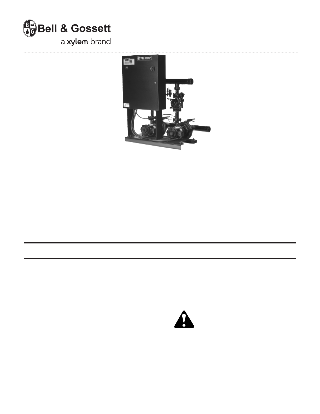
70E/70M Multiple Pump & Control
Pressure Booster Systems
INSTALLER: PLEASE LEAVE THIS MANUAL FOR THE OWNER’S USE.
DESCRIPTION
Microprocessor controlled frame mounted multiple pump
pressure boosting system with combination pressure reducing
and non-slam check valves for maintaining system pressure.
The motors are controlled by a control panel with microprocessor, starters, overload protection, virtual H-O-A switches,
optional short circuit protection, and control transformer.
The microprocessor control consists of an operator interface
with 2 line backlit display and membrane key pad, input/
output board with 24V power supply, and microcontrolled
kW transducer.
OPERATIONAL LIMITS
See unit nameplate for pump capacity, boost, full load current
draw, and operating voltage. The pump discharge pressure
must not exceed 125 PSI unless special piping modifications
are made.
SAFETY
INSTRUCTION
This safety alert symbol will be used in this manual and on the
70E/70M Safety Instruction decal to draw attention to safety
related instructions. When used, the safety alert symbol means
ATTENTION! BECOME ALERT! YOUR SAFETY IS
INVOLVED! FAILURE TO FOLLOW THESE INSTRUCTIONS
MAY RESULT IN A SAFETY HAZARD!
Page 2
70E/70M Pressure Booster
INSTRUCTIONS
UNIT IDENTIFICATION
The unit nameplate gives identification and rating information as identified in Figure 1.
Permanent records for this unit are kept by the factory number and it must therefore be
used with all correspondence and spare parts orders.
Model No.
Factor no.
Wired for Volts Hz Ph
System FL Amps
Largest Motor HP
System Flow GPM
Suction Pressure PSIG
Discharge Pressure PSIG
Pump TDH Feet
Date Code
FIGURE 1 - 70E/70M NAMEPLATE
Page 3

Preface
The following manual describes the 70E/70M Pressure Boosters with emphasis on the new microprocessor based Technologic Controller. This unit is in the tradition of the other members of the Technologic
Control Panels as it incorporates many original, novel, and proprietary features that may only be found on
B&G controllers. Some of these features require special emphasis here.
The controller is best described as a specific purpose programmable pump controller. This means that
the hardware and software have been created for the control and diagnostics of pumps with consideration for their inherent characteristics. This results in an optimum pump controller without the cost of general purpose control hardware. Software is dedicated and established for the unit only after extensive
testing. Changes to this software are not taken lightly and must pass rigid version control.
The controller has the unique patented analog input protection of other members of the control family.
Upon inadvertent higher than normal input voltage the analog input resistor is sacrificed. An on-board
spare is used to replace the plug-in resistor. Extreme hi-voltage is protected against by additional
components.
Unique to this new controller are virtual selector switches. Microprocessor control coupled with discrete
logic allows the pump keys to act as 3 position selector switches. The 3 positions are hand-off-auto.
Virtual selector switches surpass standard selector switches in that they can be changed from auto to
hand automatically upon a fault in order to maintain a process. It is novel that just as a standard selector
switch can change position (by human hand) with power off, so can the virtual selector switch similarly
change position.
Combined with the virtual selector switches is redundant control with discrete logic which is activated
upon a microprocessor fault. This is explained in detail in Section 5.4.
In addition to this unique hardware the controller has provision for three 4-20mA analog signals and two
RTD temperature inputs. Bell & Gossett is able to offer suction, system, and temperature inputs as standard. The third 4-20mA is used for an optional flow transmitter.
Bell & Gossett is thereby able to offer staging of pumps by any one of 4 methods, i.e.: watts, amps, PSI
and GPM (flow). The main changes occur in the menu entries.
Staging by watts is standard. A power transducer of Bell & Gossett design is included. This transducer is
factory calibrated, single conductor sensing, wide current and voltage range, and automatic adaptability
to Wye or Delta systems either grounded or ungrounded. At the customer’s discretion it may be used for
amp staging with the watt feature used to display total system power.
3
Page 4

TABLE OF CONTENTS
SECTION 1 – GENERAL
Purpose of Manual . . . . . . . . . . . . . . . . . . . . . . . . . . . . . . . . . . . . . . . . . . . . . . . . . . . . . . . . . . . . . . . . 6
Safety Instruction . . . . . . . . . . . . . . . . . . . . . . . . . . . . . . . . . . . . . . . . . . . . . . . . . . . . . . . . . . . . . . . . . 6
Additional Safety Requirement . . . . . . . . . . . . . . . . . . . . . . . . . . . . . . . . . . . . . . . . . . . . . . . . . . . . . . . 6
Storage . . . . . . . . . . . . . . . . . . . . . . . . . . . . . . . . . . . . . . . . . . . . . . . . . . . . . . . . . . . . . . . . . . . . . . . . . 6
Handling . . . . . . . . . . . . . . . . . . . . . . . . . . . . . . . . . . . . . . . . . . . . . . . . . . . . . . . . . . . . . . . . . . . . . . . . 6
Temperature and Ventilation . . . . . . . . . . . . . . . . . . . . . . . . . . . . . . . . . . . . . . . . . . . . . . . . . . . . . . . . . 6
Ground Connections . . . . . . . . . . . . . . . . . . . . . . . . . . . . . . . . . . . . . . . . . . . . . . . . . . . . . . . . . . . . . . . 6
Power Wiring . . . . . . . . . . . . . . . . . . . . . . . . . . . . . . . . . . . . . . . . . . . . . . . . . . . . . . . . . . . . . . . . . . . . . 6
Field Connection Diagrams . . . . . . . . . . . . . . . . . . . . . . . . . . . . . . . . . . . . . . . . . . . . . . . . . . . . . . . . . 6
SECTION 2 – INSTALLATION
Location . . . . . . . . . . . . . . . . . . . . . . . . . . . . . . . . . . . . . . . . . . . . . . . . . . . . . . . . . . . . . . . . . . . . . . . . 7
Installation . . . . . . . . . . . . . . . . . . . . . . . . . . . . . . . . . . . . . . . . . . . . . . . . . . . . . . . . . . . . . . . . . . . . . . . 7
Leveling . . . . . . . . . . . . . . . . . . . . . . . . . . . . . . . . . . . . . . . . . . . . . . . . . . . . . . . . . . . . . . . . . . . . . . . . . 7
Unit Support and Location . . . . . . . . . . . . . . . . . . . . . . . . . . . . . . . . . . . . . . . . . . . . . . . . . . . . . . . . . . 7
Piping . . . . . . . . . . . . . . . . . . . . . . . . . . . . . . . . . . . . . . . . . . . . . . . . . . . . . . . . . . . . . . . . . . . . . . . . . . 7
Lubrication . . . . . . . . . . . . . . . . . . . . . . . . . . . . . . . . . . . . . . . . . . . . . . . . . . . . . . . . . . . . . . . . . . . . . . 7
Wiring
Power Wiring . . . . . . . . . . . . . . . . . . . . . . . . . . . . . . . . . . . . . . . . . . . . . . . . . . . . . . . . . . . . . . . . . . 7
Analog Signal Wiring . . . . . . . . . . . . . . . . . . . . . . . . . . . . . . . . . . . . . . . . . . . . . . . . . . . . . . . . . . . . 7
Pressure Transmitter Wiring . . . . . . . . . . . . . . . . . . . . . . . . . . . . . . . . . . . . . . . . . . . . . . . . . . . . . . . 8
Temperature Sensor Wiring . . . . . . . . . . . . . . . . . . . . . . . . . . . . . . . . . . . . . . . . . . . . . . . . . . . . . . . 8
Flow Sensor/Transmitter Wiring and Installation . . . . . . . . . . . . . . . . . . . . . . . . . . . . . . . . . . . . . . . 8
Differential Pressure Switch Piping and Wiring . . . . . . . . . . . . . . . . . . . . . . . . . . . . . . . . . . . . . . . . 8
Remote Start/Stop . . . . . . . . . . . . . . . . . . . . . . . . . . . . . . . . . . . . . . . . . . . . . . . . . . . . . . . . . . . . . . 8
Remote Alarm Indication . . . . . . . . . . . . . . . . . . . . . . . . . . . . . . . . . . . . . . . . . . . . . . . . . . . . . . . . . 8
Pump On/Off Remote Signal . . . . . . . . . . . . . . . . . . . . . . . . . . . . . . . . . . . . . . . . . . . . . . . . . . . . . . 8
SECTION 3 – START UP
Putting Unit into Service . . . . . . . . . . . . . . . . . . . . . . . . . . . . . . . . . . . . . . . . . . . . . . . . . . . . . . . . . . . . 8
SECTION 4 – SETUP AND FEATURES
Power-Up . . . . . . . . . . . . . . . . . . . . . . . . . . . . . . . . . . . . . . . . . . . . . . . . . . . . . . . . . . . . . . . . . . . . . . . 9
Setup and System Configuration . . . . . . . . . . . . . . . . . . . . . . . . . . . . . . . . . . . . . . . . . . . . . . . . . . . . . 9
Key Functions . . . . . . . . . . . . . . . . . . . . . . . . . . . . . . . . . . . . . . . . . . . . . . . . . . . . . . . . . . . . . . . . . . . . 12
Normal Operating Messages . . . . . . . . . . . . . . . . . . . . . . . . . . . . . . . . . . . . . . . . . . . . . . . . . . . . . . . . 13
Alarms . . . . . . . . . . . . . . . . . . . . . . . . . . . . . . . . . . . . . . . . . . . . . . . . . . . . . . . . . . . . . . . . . . . . . . . . . . 14
SECTION 5 – OPERATION
Power Up . . . . . . . . . . . . . . . . . . . . . . . . . . . . . . . . . . . . . . . . . . . . . . . . . . . . . . . . . . . . . . . . . . . . . . . 15
Auto Operation . . . . . . . . . . . . . . . . . . . . . . . . . . . . . . . . . . . . . . . . . . . . . . . . . . . . . . . . . . . . . . . . . . . 15
Manual Operation (CPU OK) . . . . . . . . . . . . . . . . . . . . . . . . . . . . . . . . . . . . . . . . . . . . . . . . . . . . . . . . . 16
Manual Operation (CPU Fails) . . . . . . . . . . . . . . . . . . . . . . . . . . . . . . . . . . . . . . . . . . . . . . . . . . . . . . . . 16
4
Page 5

SECTION 6 – MAINTENANCE
Preface . . . . . . . . . . . . . . . . . . . . . . . . . . . . . . . . . . . . . . . . . . . . . . . . . . . . . . . . . . . . . . . . . . . . . . . . . 17
Technical Overview . . . . . . . . . . . . . . . . . . . . . . . . . . . . . . . . . . . . . . . . . . . . . . . . . . . . . . . . . . . . . . . . 17
Digital Inputs . . . . . . . . . . . . . . . . . . . . . . . . . . . . . . . . . . . . . . . . . . . . . . . . . . . . . . . . . . . . . . . . . . . . . 17
Digital Outputs . . . . . . . . . . . . . . . . . . . . . . . . . . . . . . . . . . . . . . . . . . . . . . . . . . . . . . . . . . . . . . . . . . . 17
Analog Inputs . . . . . . . . . . . . . . . . . . . . . . . . . . . . . . . . . . . . . . . . . . . . . . . . . . . . . . . . . . . . . . . . . . . . 17
Memory . . . . . . . . . . . . . . . . . . . . . . . . . . . . . . . . . . . . . . . . . . . . . . . . . . . . . . . . . . . . . . . . . . . . . . . . . 17
CPU . . . . . . . . . . . . . . . . . . . . . . . . . . . . . . . . . . . . . . . . . . . . . . . . . . . . . . . . . . . . . . . . . . . . . . . . . . . . 17
Power Supply . . . . . . . . . . . . . . . . . . . . . . . . . . . . . . . . . . . . . . . . . . . . . . . . . . . . . . . . . . . . . . . . . . . . 17
Diagnostics (Service Test) . . . . . . . . . . . . . . . . . . . . . . . . . . . . . . . . . . . . . . . . . . . . . . . . . . . . . . . . . . 17
Read Only – Digital Inputs . . . . . . . . . . . . . . . . . . . . . . . . . . . . . . . . . . . . . . . . . . . . . . . . . . . . . . . . . . 17
Read Only – Analog Inputs . . . . . . . . . . . . . . . . . . . . . . . . . . . . . . . . . . . . . . . . . . . . . . . . . . . . . . . . . . 18
Manual Control – Outputs . . . . . . . . . . . . . . . . . . . . . . . . . . . . . . . . . . . . . . . . . . . . . . . . . . . . . . . . . . . 18
Digital Outputs . . . . . . . . . . . . . . . . . . . . . . . . . . . . . . . . . . . . . . . . . . . . . . . . . . . . . . . . . . . . . . . . . . . 18
Pre-Determined Fault and Fault Control . . . . . . . . . . . . . . . . . . . . . . . . . . . . . . . . . . . . . . . . . . . . . . . . 19
Protection . . . . . . . . . . . . . . . . . . . . . . . . . . . . . . . . . . . . . . . . . . . . . . . . . . . . . . . . . . . . . . . . . . . . . . . 19
Fault Isolation . . . . . . . . . . . . . . . . . . . . . . . . . . . . . . . . . . . . . . . . . . . . . . . . . . . . . . . . . . . . . . . . . . . . 19
Instruments and Their Use . . . . . . . . . . . . . . . . . . . . . . . . . . . . . . . . . . . . . . . . . . . . . . . . . . . . . . . . . . 21
Field Repair . . . . . . . . . . . . . . . . . . . . . . . . . . . . . . . . . . . . . . . . . . . . . . . . . . . . . . . . . . . . . . . . . . . . . . 21
Serial No. and Firmware Version No. . . . . . . . . . . . . . . . . . . . . . . . . . . . . . . . . . . . . . . . . . . . . . . . . . . 21
Maintenance (Physical) . . . . . . . . . . . . . . . . . . . . . . . . . . . . . . . . . . . . . . . . . . . . . . . . . . . . . . . . . . . . . 21
APPENDIX A
System Piping and Unit Installation – Final Check List . . . . . . . . . . . . . . . . . . . . . . . . . . . . . . . . . . . . 22
APPENDIX B
Electrical Wiring and Control Settings – Final Check List . . . . . . . . . . . . . . . . . . . . . . . . . . . . . . . . . . . 22
APPENDIX C
Procedure for Field Balancing 70E/70M PRV’s . . . . . . . . . . . . . . . . . . . . . . . . . . . . . . . . . . . . . . . . . . 23
APPENDIX D
Troubleshooting Combination Pressure Reducing and Check Valves . . . . . . . . . . . . . . . . . . . . . . . . . 24
PRV Repair Kits . . . . . . . . . . . . . . . . . . . . . . . . . . . . . . . . . . . . . . . . . . . . . . . . . . . . . . . . . . . . . . . . . . 26
APPENDIX E
Service Test Overview . . . . . . . . . . . . . . . . . . . . . . . . . . . . . . . . . . . . . . . . . . . . . . . . . . . . . . . . . . . . . 27
APPENDIX F
Power Transducer Board (PTB) . . . . . . . . . . . . . . . . . . . . . . . . . . . . . . . . . . . . . . . . . . . . . . . . . . . . . . 27
NOTE:
The information contained in this manual is intended to assist operating personnel by providing information
on the characteristics of the purchased equipment.
It does not relieve the user of the responsibility to adhere to local codes and ordinances and the use of
accepted practices in the installation, operation and maintenance of this equipment.
Further information pertaining to the installation, operation, and maintenance of your 70E/70M Pressure
Boosting System can be found in the I.O.M.s for the associated equipment provided:
A. Bell & Gossett 1510 (IOM Part #P81673)
B. Bell & Gossett 1531 (IOM Part #P81567)
C. Pressure Reducing Valve – CLA-VAL Co. Manual #TM90-01
D. Flow Sensor/Transmitter Manufacturers IOM
5
Page 6
SECTION 1 – GENERAL
1.1 PURPOSE OF MANUAL
1.1.1 This manual is furnished to acquaint you with some
1.1.2 Equipment cannot operate well without proper care.
1.1.3
1.1.4 Your Technologic 70E/70M Series Pump Controller
1.2
1.2.1 Motor must have a properly sized starter with properly
1.2.2 Refer to the motor manufacturer’s I.O.M. for specific
1.2.3 Even when the motor is stopped, it should be consid-
1.2.4 Motor control equipment and electronic controls are
of the practical ways to install, operate, and maintain
this unit. Read it carefully before doing any work on
your unit and keep it handy for future reference.
To keep this unit at top efficiency, follow the recommended installation and servicing procedures outlined in this manual.
SAFETY INSTRUCTION
This safety alert symbol will be used in this manual
and on the unit safety instruction to draw attention to
safety related instructions. When used the safety alert
symbol means
YOUR SAFETY IS INVOLVED! FAILURE TO FOLLOW THIS INSTRUCTION MAY RESULT IN A
SAFETY HAZARD.
should have a safety instruction decal (Part #S11550).
If the decal is missing or illegible contact your local
B&G representative for a replacement.
ADDITIONAL SAFETY REQUIREMENTS
sized overload block to provide overload and undervoltage protection. Ground fault protection should be
sized properly.
installation information.
ered “alive” as long as its controller is energized.
Keep hands away from the output shaft until the
motor has completely stopped and power is disconnected from the pump controller.
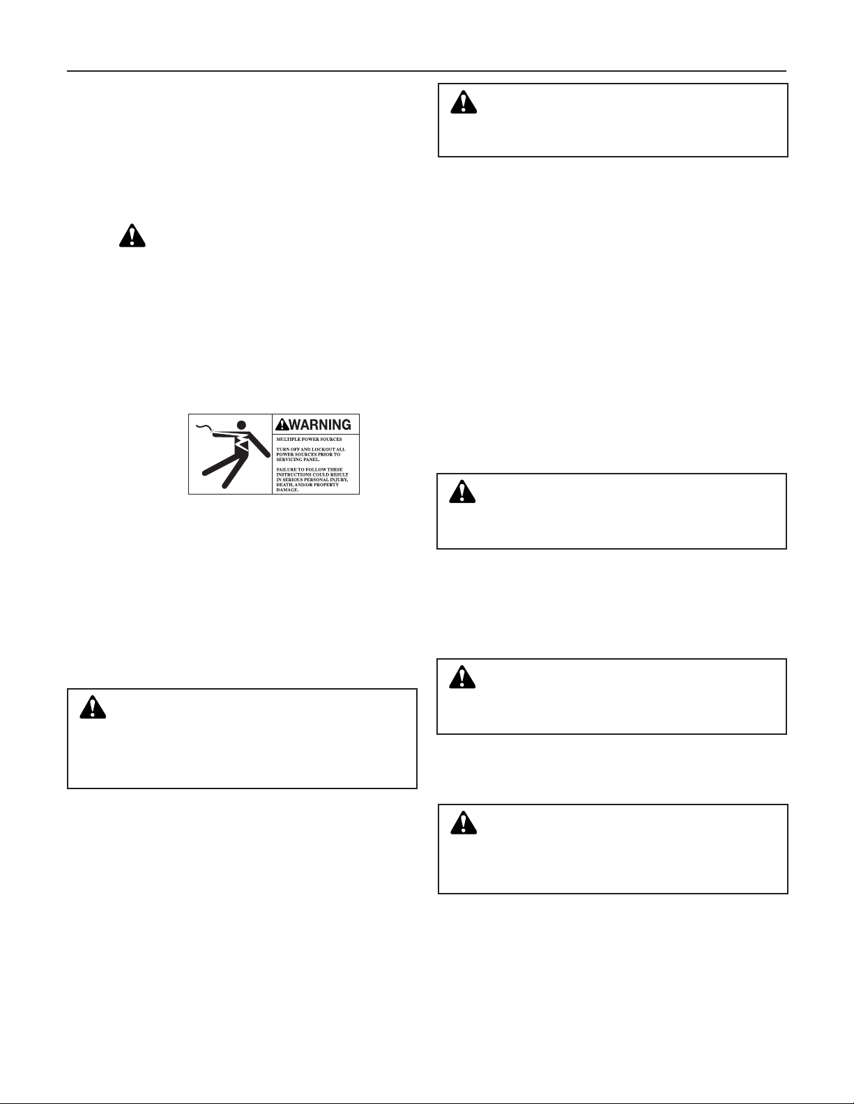
WARNING: Motor can start automatically. Keeps
hands away from output shaft until motor is completely stopped and input power is removed from the
motor control panel. Lockout main power switch while
working near the motor shaft.
instructions could result in serious personal injury,
death, and/or property damage.
connected to hazardous line voltages. When servicing electronic controls, there will be exposed components at or above line potential. Extreme care should
be taken to protect against shock. Stand on an insulating pad and make it a habit to use only one hand
when checking components. Always use accurate
test meters when checking electrical components.
Always work with another person in case of an emergency. Disconnect power when performing maintenance. Be sure equipment is properly grounded.
Wear safety glasses whenever working on electronic
control or rotating equipment.
ATTENTION BECOME ALERT!
Failure to follow these
DANGER: Troubleshooting live control panels ex-
poses personnel to hazardous voltages. Electrical
troubleshooting must only be done by a qualified electrician. Failure to follow these instructions could result in
serious personal injury, death, and/or property damage.
1.3
1.4
1.4.1 Care should be taken to prevent damage due to
1.4.2 The units should be unloaded and handled by quali-
1.5
1.6
1.7
STORAGE
For long periods of storage, the unit should be covered to prevent corrosion and contamination from
dirt. It should be STORED in a clean, dry location
between -20 and +75˚C. The relative humidity should
not exceed 85%. The unit should be checked periodically to ensure that no condensation has formed.
After storage, again check that it is dry before applying power.
HANDLING
dropping or jolting when moving the unit. Inspect the
unit thoroughly for damage upon receipt.
Transportation damage should be brought to the carrier’s attention immediately. Ensure that sensing lines
are free of crimps and kinks.
fied personnel. The unit is top heavy due to the position of the motors. Use the motor eyebolts to stabilize
the unit while lifting to prevent overturning. Do not
use the motor eyebolts to lift.
WARNING: Falling Objects Hazard. Eyebolts or lifting lugs, if provided, are for lifting only the compo-
nents to which they are attached.
instructions could result in serious personal injury,
death, and/or property damage.
TEMPERATURE AND VENTILATION
All electrical equipment is susceptible to failure if
operated in ambient temperatures outside of its rating. The OPERATING temperature range for this unit
is 0 to 40˚C. The relative humidity should not exceed
95% non-condensing. The unit should not be operated outside these extremes.
WARNING: Prevent electrical shocks. Disconnect
the power supply before beginning installation.
Failure to follow these instructions could result
in serious personal injury, death, and/or property
damage.
GROUND CONNECTIONS
A grounding terminal is provided for a dedicated
ground wire connection. All provisions of the National
Electrical Code and local codes must be followed.
WARNING: Conduit grounds are not adequate. A
separate ground wire must be attached to the
ground lug provided in the enclosure to avoid potential
safety hazards.
could result in serious personal injury, death, and/or
property damage.
POWER WIRING
Power wire types and sizes must be selected based
upon conformance with the National Electrical Code
and all local codes and restrictions. In addition, only
copper (Cu) wire rated for 75˚C (minimum) may be
used for the power connections. Refer to the input
current as listed on the nameplate on the enclosure
door when sizing wire.
Failure to follow these instructions
Failure to follow these
6
Page 7
1.8 FIELD CONNECTION DIAGRAMS
1.8.1 Refer to the pump Installation, Operation, and Maintenance Manual for specific details unique to the
pump.
1.8.2 Refer to the flow sensor/transmitter Installation,
Operation, and Maintenance Manual for specific
details unique to the flow sensor/transmitter.
SECTION 2 – INSTALLATION
1.8.3 The following field connection diagrams should be
reviewed prior to unit installation and operation.
Drawing # Description
Job Specific Print(s) Wiring Diagram(s)
Job Specific Print Dimensional Drawings
2.0 LOCATION
2.1 Locate the pumping unit for ease of inspection, maintenance and service.
DANGER: Heavy load, may drop if not lifted properly. Do not lift the entire unit by the motor eyebolts.
Lift the unit with slings placed under the unit base rails.
Failure to follow these instructions could result
in serious personal injury, death, and/or property
damage.
2.2
INSTALLATION
This unit is built to give you years of service; install it
properly and provide a suitable foundation. A base of
concrete weighing 2
1
/2 times the weight of the unit is
recommended. (Check the shipping ticket for the unit
weight.) Tie the concrete pad in with the finished
floor. Use foundation bolts and larger pipe sleeves to
give room for final bolt location.
2.3
LEVELING
Place the unit on its concrete foundation, supporting
it with steel wedges or shims totaling 1" in thickness.
These wedges or shims should be put on both sides
of each anchor-bolt to provide a means of leveling
the base.
2.4
UNIT SUPPORT AND LOCATION
The Bell & Gossett Series 70E/70M Pressure Booster
should be installed where there will be sufficient room
for future inspection and service. If the unit is to be
located near a noise sensitive area, consult a sound
specialist. Special precautions should be taken to
avoid sound and vibration transmission.
2.5
PIPING
2.5.1 Important. Do not install and operate Bell &
Gossett 70E/70M Pressure Booster in a closed system unless the system is constructed with properly
sized devices and control devices. Such devices
include the use of properly sized and located pressure relief valves, compression tanks, pressure controls, temperature controls and flow controls as
appropriate. If the system does not include these
devices, consult the responsible engineer or architect
before making pumps operational.
DANGER: The heating of water and other fluids
causes volumetric expansion. The associated forces
may cause failure of system components and releases of
high temperature fluids. This will by prevented by installing properly sized and located pressure relief valves and
compression tanks.
Failure to follow these instructions
could result in serious property damage and serious
personal injury or death.
2.5.2 Make all necessay system piping connections. Be
aware that connecting dissimilar metals to the headers
can lead to corrosion damage due to galvanic corro-
sion. The rate of corrosion is dependant on various
factors some of which are: the potential between the
dissimilar metals, electrolyte conductivity, geometry
and areas of the metals. Dielectric connections are
recommended between dissimilar metals at the
header connection. Be sure to eliminate any pipe
strain on the unit. Support all pipes independently by
use of pipe hangers near the unit. DO NOT ATTEMPT
TO FORCE THE SUCTION OR DISCHARGE LINES
INTO POSITION. Refer to assembly drawing for customer piping connections.
2.5.3 Eccentric increasers can be used in the suction lines
when increasing the pipe size, with straight sides of
increaser on top to eliminate air pockets.
2.5.4 As a rule, ordinary wire or band hangers are not adequate to maintain alignment. It is very important to
provide a strong, rigid support for the suction line. A
saddle hanger is recommended.
2.5.5 For critical installations, equipment for absorbing
expansion and vibration should be installed in the
inlet and outlet connections of the unit.
2.5.6 After hydrotesting, drain plugs are removed, to facilitate system drainage, placed in a cloth bag and
secured to the unit. Drain plugs shall be reinstalled
prior to filling the system with fluid. Inspect all unit
piping connections. Joints may also become loose
during transit due to vibration and shock. All joints
are to be checked for tightness. Flanged joints should
be checked for proper torque of all flange bolts prior
to filling the system with fluid.
CAUTION: Failure to reinstall drain plugs, check all
joints for tighteness and flange bolts for proper
torque could result in leaks and/or flooding. Failure to
follow these instructions could result in property
damage and or moderate personal injury.
2.5.7 On an open system with a suction lift, use a foot
valve of equal or greater area than the pump suction
piping. Prevent clogging by using a strainer at the
suction inlet next to the foot valve. The strainer
should have an area three times that of the suction
pipe. Provisions must be made to prime the pump
suction piping on start up. Do not start the pump
unless all suction piping is full of water.
2.5.8 A thermal relief valve (B&G Part #S51260) is installed
on the discharge header to prevent potentially dangerous thermal buildup in the package. This valve
acts as a safety device and it should never be removed or tampered with. It is factory set to open and
discharge when the water temperature in the discharge header exceeds 125˚F. The
3
/8" NPT opening
of this valve must be piped to a floor drain.
2.6
LUBRICATION
Before starting, all pumps and motors should be
checked for proper lubrication.
7
Page 8
DANGER: Electrical shock hazard. Inspect all elec-
trical connections prior to powering the unit. Wiring
connections must be made by a qualified electrician in
accordance with all applicable codes, ordinances, and
good practices. Failure to follow these instructions
could result in serious personal injury, death, and/or
property damage.
2.7 WIRING
2.7.1 POWER WIRING
The 70E/70M Pump Control Panel can be set up to
operate across a broad range of voltages. It was factory set to operate on the voltage shown on the
nameplate. Verify proper transformer primary wiring
per the job-specific wiring diagram. Check power
leads in accordance with wiring diagram enclosed in
control cabinet. The voltage tolerance is +10%/-10%.
2.7.2
2.7.2.1
ANALOG SIGNAL WIRING
If installing the panel on an existing system, shielded
cable (#22 AWG, Belden type 8762, Alpha #2411 or
equal) should be installed for the DC control wiring.
The shield must be terminated in the 70E/70M control panel. Do not connect the shield at the other end
of the cable! Insulate the shield so that no electrical
connection is made at the other end of the cable. A
twisted pair of #22 AWG conductors (Belden 8442 or
equal) can be used in place of shielded cable. The
cable length must be limited to 3000 feet for #22
AWG wire.
PRESSURE TRANSMITTER WIRING
(4-20 mA Analog Signals)
horizontal installation (see manufacturer’s IOM). See
the Bell & Gossett drawing for installation instructions. The signal wiring should be terminated in the
70E/70M panel at the terminals below.
Optional Flow Sensor/Transmitter + - Shield
Terminals (J3) 9 8 10
2.7.3
2.7.3.1 DIFFERENTIAL PRESSURE SWITCH PIPING
2.7.3.2
DIGITAL SIGNAL WIRING
AND WIRING (Digital Signal) (Optional)
Differential pressure switches installed to sense the
increase in pressure between the pump suction and
discharge gauge taps are used to determine whether
a pump is running. Each switch should be wired from
the normally closed contact to the terminals below.
Pump # 1 2 3
Terminals (J4) 9, 8 10, 11 11, 12
LOW LEVEL CONTROL WIRING
(Digital Signal) (Optional)
The low water level control option is utilized when
drawing water from a tank. In this control circuit, two
electrodes sense the water level inside of a water
tank. When the water level drops below its minimum
level, the pressure booster will shut down.
Pump On Pump Off
Ground Electrode Electrode
Terminals (J4) 66 67 68
Terminals (J3) + - Shield
Suction Pressure 3 2 4
System (discharge) Pressure 3 6 4
2.7.2.2 TEMPERATURE SENSOR WIRING
2.7.2.3
(Analog Resistance Input)
The 70E/70M uses resistance temperature detectors
(RTDs) to sense the suction and discharge water
temperatures. These devices change their resistance
as the water temperature changes.
Temperature Sensor (RTD) Wiring Terminals (J3)
Low Temperature Sensor (suction) 13, 14
High Temperature Sensor (discharge) 16, 17
FLOW SENSOR/TRANSMITTER WIRING AND
INSTALLATION (4-20 mA Analog Signal) (Optional)
The flow sensor should be installed at an angle no
greater than 45 degrees from top dead center in a
SECTION 3 – START UP
3.0 PUTTING THE UNIT INTO SERVICE
3.1 PUMP ROTATION, 3 PHASE MOTORS ONLY
CAUTION: Seal Damage may occur. Do not run
pumps dry. Fill and vent the pump volute prior to
operation. Failure to follow these instructions could re-
sult in property damage and/or moderate personal injury.
WARNING: Rotating shafts can catch loose cloth-
ing. Do not operate the pump without all guards in
place.
Failure to follow these instructions could result in
serious personal injury, death, and/or property damage.
8
2.7.3.3
2.7.3.4
2.7.3.5
3.2 If incorrect, turn the main disconnect off and inter-
3.3 Unit is now ready for operation (factory assembled
REMOTE START-STOP (Digital)
Install a non-powered dry contact digital input to terminals J4-1 and J4-2. With the LOCAL-REMOTEOFF switch in the REMOTE position this contact
closure will provide the start signal.
REMOTE ALARM INDICATION (Digital Signal)
A digital output dry contact rated 2 Amps at 115V is
supplied on terminals J5-7 and J5-8. This output
closes to indicate that an alarm condition exists.
PUMP ON/OFF REMOTE SIGNAL (Digital Signal)
A digital output dry contact (one per pump) rated 2
Amps at 115V is provided for remote monitoring of
pump On/Off status. This contact closes when a
pump is running.
Pump On/Off Signal Pump #1 Pump #2 Pump #3
Terminals (J5) 9, 10 11, 12 13, 14
With the disconnect switch engaged to the “ON”
position, momentarily
the pump motor key on the key pad. See Paragraph
5.3 on page 16. Observe the pump shaft rotation.
change any two wire leads leaving the starter overload block and going to the motor.
DANGER: High Voltage 3 phase power can kill.
Disconnect and lockout power prior to servicing
unit.
Failure to follow these instructions could result in
serious personal injury, death, and/or property damage.
tested units only).
start and stop each motor with
Page 9
SECTION 4 – SETUP AND FEATURES
4.1 GENERAL NOTES
4.1.1 The HELP key can be pressed at any time without
4.1.2 The key names are shown in CAPITAL LETTERS and
4.2 POWER-UP
4.2.1 Put LOCAL-REMOTE-OFF (LRO) switch in the
4.2.2 Turn main disconnect on.
disrupting system operation. The HELP key will give
details on alarm conditions or if used in conjunction
with any function key will give a detailed explanation
of the function key application.
the operator interface responses are shown in bold
CAPITAL LETTERS.
WARNING: Electrical shock hazard. Inspect all elec-
trical connections prior to powering the unit. Wiring
connections must be made by a qualified electrician in
accordance with all applicable codes, ordinances, and
good practices.
could result in serious personal injury, death, and/or
property damage.
LOCAL position.
WARNING: Electrical shock hazard. Multiple power
sources. The off position of the LOCAL-REMOTEOFF switch does not disconnect all of the power sources
in the technologic panel. All power sources must be disconnected prior to entering the control panel. Failure to
follow these instructions could result in serious personal injury, death, and/or property damage.
Failure to follow these instructions
4.2.3 The operator interface will display the ITT Bell &
4.2.4 The operator interface will perform a lamp test and
4.2.5 Press CLEAR to stop the test.
4.2.6 The START-STOP led will be red.
4.2.7 If the START-STOP led is not illuminated as des-
4.2.8 The Auto-Hand led should be green for auto opera-
4.2.9 Press the PUMP 1 ON/OFF key to obtain a flashing
4.3
4.3.1 Press the SETUP key. Enter the serial number of the
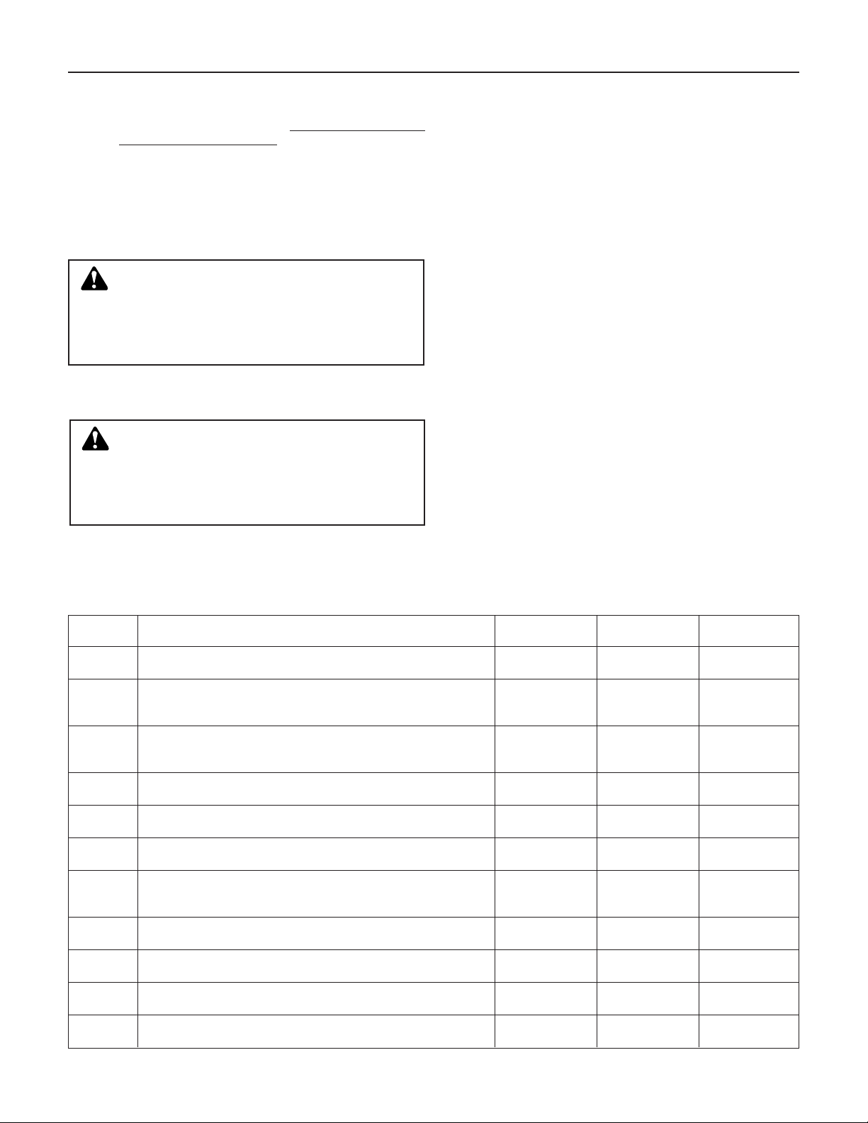
4.3.2 Confirm the system setup values per the following
Gossett corporation signature.
display test.
cribed above, press the START-STOP button once to
obtain the red LED.
tion. If not green, press the AUTO-HAND key to
obtain green led.
green light. On two pump systems, press the PUMP
2 ON/OFF key to obtain a flashing green LED and
press PUMP 3 ON/OFF key, for 3 pump systems, to
obtain a flashing green LED. Refer to Section 5 for
operation.
SETUP & SYSTEM CONFIGURATION
assembly by pressing the appropriate numeric keys.
Press the ENTER key. The serial number may always
be found by reading the 4th message after power up
and the word “booting” disappears.
table. Use the UP or DOWN ARROW keys to move
through the menu. To change values, press ENTER,
modify the value using the numeric key pad or UP and
DOWN ARROW keys, press ENTER to accept the
modification.
Default Allowable Field
Line # DISPLAY ➀ Value Range Values
1 Number of Pumps 1
Number of Pumps on the System (1-2-3)
2 Alternation Sequence None
Use up/down keys to select: None, Duplex, Triplex - all, None As Listed
Triplex - 132A
3 Auto Alt. Period 0
O = Manual only, for Auto Enter 0 0 - 6553
Alternation period in hours
4 Reset Pump 1 Time No
Yes = arrow key to reset
5 Reset Pump 2 Time No
Yes = arrow key to reset
6 Reset Pump 3 Time No
Yes = arrow key to reset
7 Staging Type Watts
Use up/down keys to select the primary method of Watts As Listed
pump staging: Watts, AMPs, PSI, GPM, TEMP
8 Pump #1 HP 0
Enter Motor #1 nameplate horsepower
9 Pump #2 HP 0
Enter Motor #2 nameplate horsepower
10 Pump #3 HP 0
Enter Motor #3 nameplate horsepower
11 Pump 1 AMPs 0
Enter Motor #1 nameplate FLA
1 1 - 3
No Y/N
No Y/N
No Y/N
0 0 - 99.9
0 0 - 99.9
0 0 - 99.9
0 0 - 175
9
Page 10

Default Allowable Field
Line # DISPLAY ➀ Value Range Values
12 Pump 2 AMPs 0
Enter Motor #2 nameplate FLA
13 Pump 3 AMPs 0
Enter Motor #3 nameplate FLA
14 Pump #1 GPM 0
Enter Staging GPM of Pump #1
15 Pump #2 GPM 0
Enter Staging GPM of Pump #2
16 Pump #3 GPM 0
Enter Staging GPM of Pump #3
0 0 - 175
0 0 - 175
0 0 - 30,000
0 0 - 30,000
0 0 - 30,000
17 1 - 2 Stage % 80
Enter percent of NPHP, NPFLA, or GPM to stage 2nd
pump in sequence
80 0 - 100
18 2 - 3 Stage % 80
Enter percent of NPHP, NPFLA or GPM to stage 3rd
pump in sequence
80 0 - 100
19 Destage % 90
Enter percent of stage percent for destaging with HP,
AMPs, or GPM only
90 0 - 99
20 Staging PSI 0
Enter pressure to stage in PSI mode after entering system 0 0 - System Span
pressure span (see Line 38)
21 Destaging PSI
Enter pressure to destage in PSI mode after entering system 0 0 - System Span
pressure span (see Line 38)
22 Forced Destg Tmr. 60
Enter in minutes (0 - 99) value of a timer after which the 60 0 - 99
pump will be forced to de-stage; ‘0’ disables this function
23 GPM Xmiter Span
Enter value equal to GPM transmitter calibration
24 2nd Stage Proof 2
2nd pump stage proof time in seconds
25 3rd Stage Proof 2
3rd pump stage proof time in seconds
26 Display Watts YES
Use up/down keys to enter yes or no
0 0 - 30,000
5 1 - 180
5 1 - 180
Yes Y/N
27 Three phase Watts YES
Use up/down keys to enter yes or no, YES = three phase, Yes Y/N
NO = single phase
28 Display AMPs YES
Use up/down keys to enter yes or no
29 Display GPM No
Use up/down keys to enter yes or no
30 Suction Press. Span 100
Enter value equal to suction pressure span
Yes Y/N
No Y/N
100 0 - 999
31 High Suct. Press. 0
Enter value of the high suction pressure above which an 0 0 - 100
alarm will be set
32 High Suct. Pr. TMR. 0
Enter in seconds (0 - 999) value of high suction cutout 0 0 - 999
proof timer, ‘0’ disables this function
33 High Suct. Reset 0
Enter value of the high suction reset pressure
0 0 - 100
34 Low Suct. Press. 5
Enter value of the low suction pressure below which an 5 0 - 100
alarm will be set
35 Low Suct. Pr. TMR. 20
Enter in seconds (0 - 999) value of low suction proof timer; 20 0 - 999
‘0’ disables this function
36 Low Suct. Reset 10
Enter value of the low suction reset pressure
10
10 0 - 100
Page 11

37 Low Suct. Auto RST Yes
To change the Low Suction reset, use UP/DOWN key Yes Y/N
to enter yes or no
38 System Press. Span 300
Enter value equal to system pressure span
300 0 - 999
39 High Sys. Press. 125
Enter value of the high system pressure above 125 0 - SPAN
which an alarm will be set
40 High Sys. PR. TMR. 20
Enter in seconds (0 - 60) value of proof timer, 20 0 - 60
‘0’ disables this function
41 Audible Alarm 0
Enter 1 for low suction only, 2 for high system only, 3 for 0 0 - 3
low suction and high system, 0 to disable audible alarm
42 Low Sys. Press. 0
Enter value of low system pressure below 0 0 - Span
which an alarm will be set
43 Low Sys. Pr. Tmr. 0
Enter in seconds (0 - 60) value of proof timer, 0 0 - 60
‘0’ disables this function
44 High Temp Cut Out 125
Enter value of the high temp cut-out in deg. F above 125 0 - 200
which an alarm will be set
45 High Temp PR. TMR. 20
Enter in seconds (0 - 60) value of proof timer, 20 0 - 60
‘0’ disables this function
46 High Temp. Reset 100
Enter value of the high temp. Reset in deg. F
100 0 - 199
47 FS NFSD PR TMR
Enter in seconds (5 - 60) value of the 0 5-60
no flow condition proof timer, ‘0’ disables the function
48 NFSD Temp. Cut Out 0
Enter NFSD temp differential, ‘0’ disables this function
5 0-10
49 NFSD Min. Run TMR. 10
Time period (minutes) to ignore no flow sequence 10 0 - 999
after restart from no flow shut down
50 NFSD Restart PSI 0
Enter value of system pressure to restart
0 0 - SPAN
51 NFSD Test Pr. TMR. 0
Enter in seconds (0 - 999), value of the no flow condition 0 0 - 999
proof timer ‘0’ disables this function
52 DP 1 Start Time 30
Time period in seconds to allow pump 1 to start prior 30 15-60
to detecting pump failure
53 DP2 Start Time 30
Time period in seconds to allow pump 2 to start prior 30 15-60
to detecting pump failure
54 DP3 Start Time 30
Time period in seconds to allow pump 3 to start prior to 30 15-60
detecting pump failure
55 DP 1 Proof Time 3
Pump #1 failure proof time in seconds
56 DP 2 Proof Time 3
Pump #2 failure proof time in seconds
57 DP 3 Proof Time 3
Pump #3 failure proof time in seconds
58 Minimum Run Timer 5
Minimum time a pump will run after auto start in minutes
3 0-30
3 0-30
3 0-30
5 0-25
59 Backup Staging WATTS, AMPS,
Select method of backup staging in the event WATTS PSI, GPM,
the primary method fails TEMP
11
Page 12

60 TEMP Xmitr Span
Enter value equal to remote temperate transmitter span.
Note this input is used for temperature staging requiring
0 999
a 4-20mA temperature transmitter.
61 Stage TEMP Rise
Select yes to stage pumps on temperature rise Yes Y/N
based on setpoint.
62 Temp Staging H
Enter the high temperature for staging/destaging.
63 Temp Staging L
Enter the low temperature for staging/destaging.
75 999
50 999
64 Standby
When yes is selected disables the staging of the N Y/N
last pump in sequence.
65 DI SUC ALARM
0 = Low Level 0 0-1
1 = Low Pressure
66 DI SA PT (DI ALARM TMR)
Enter in seconds proof timer for alarm. 1 0-99
“0” disables this function.
67 Default All ? N
Set all parameters to factory default
N Y/N
4.3.3 Press the CLEAR key. You will return to the standard
operating display.
NOTES:
The top line of each display is stationary while the changeable value, if any, is flashing. The bottom line scrolls from right to left continuously. To scroll from
➀
display to display continuously press either arrows. At any display the data may be changed by pressing enter, pressing the key or keys to change data, and
pressing ENTER again. If a value to be entered is out of range the following is displayed:
Top Line - value out of range Bottom Line - X1 < = Value < = X2 With X1 being the minimum value and X2 the maximum value of the range
Note: For software version 3.28 or greater.
➁
4.4 KEY FUNCTIONS
HELP MESSAGES. PRESS HELP AFTER
CLEARING ANY ALARMS
LINE KEY MESSAGE
➀ 1 Start/Stop Used to start and stop pumps.
➁ 2 Auto/Hand Used to select auto or manual operation.
3 Pump 1 Used to start/stop pump 1; green = run, flashing green = enable,
Enable flashing red = failure.
4 Pump 2 Used to start/stop Pump 2; green = run, flashing green = enable,
Enable flashing red = failure.
5 Pump 3 Used to start/stop Pump 3; green = run, flashing green = enable,
Enable flashing red = failure.
➂ 6 Alternation Used to alternate pump sequence.
7 Service Test Used to perform service test.
8 Reset/Silence Used to reset alarm after its correction and to silence audible alarm.
9 Used for selection in a menu.
10 Set Up Used to define system parameters - security.
11 Clear Clears latest entry (operation and data).
12 Help User assistance; press: Help + Key/Item.
13 Enter Used to accept data and operation input.
In every case above the message scrolls right to left twice and blanks out. Press CLEAR twice to exit.
NOTE: Keys from Line 2 through Line 12 (except clear) also have numbers for numerical entry within a menu.
NOTES:
➀
➁
➂
➔
➔
One pump must be enabled to obtain start function. Has green - run and red - stop LED.
To change selection the START-STOP key must be in stop. Green LED-AUTO, red LED-HAND.
The alternation sequence will be according to the user menu selection and will be displayed according to the message of 4.5 below
to match that selection.
12
Page 13

4.5 NORMAL OPERATING MESSAGES
4.5.1
NORMAL SCROLL AUTO OR HAND
LOCAL OR REMOTE ➀➁
MESSAGE CONDITION
Alternation
Elapsed Time P1 Hours XXX
Elapsed Time P2 Hours XXX If 2 pumps selected
Elapsed Time P3 Hours XXX If 3 pumps selected
High suction cutout
No flow shut down
Suction Pressure PSI XX If span is entered
System Pressure PSI XX If span is entered
Suction Temperature XX F˚ If high temperature cut-out is entered
System Temperature XX F˚ If high temperature cut-out is entered
Total AMPS XXX If selected in menu
Total KW XXXX If selected in menu
Flow = XXXXX ➃GPM If span entered
* Alarm (flashing) When an alarm occurs
Startup — Standby Bottom Line Only
Alternation Engaged Standby Bottom Line Only
Pump Not Available Bottom Line Only
Please Enable a Pump Bottom Line Only
Not Allowed Bottom Line Only
User Setup Lost Top Line
Call Factory For Assistance Bottom Line Only
NOTES:
Press ENTER and ARROW keys for scroll lock.
➀
Display is blank if CPU fails.
➁
Not scrolled in hand operation.
➂
XXXX reverts to ??? if span is entered and signal is less than 4mA.
➃
* See 4.5.2 for alarm messages.
➂
➂
➂
“None” According to menu entry for simplex,
or duplex or triplex.
“1-2, 2-1”
or
“1-2-3
2-3-1”
3-1-2
or
“1-2-3
1-3-2”
Bottom Line Only
Bottom Line Only
13
Page 14

4.5.2 ALARMS
ALARMS
CONDITION HELP MESSAGE
Overload X Failure Check AMP draw, use manual reset if OK
High Suction PSI High suction pressure – check suction
Low Suction PSI Low suction detected – check suction
High System PSI High pressure detected in the system –
Low System PSI Low pressure detected in the system –
Water Level Low Check water level in holding tank
Water Temp High Check water temperature
Pump X Off Need pump in system – if OK enable pump
Suction Trans Fail Check wiring, piping, polarity, and continuity
System Trans Fail Check wiring, piping, polarity, and continuity
Flow Trans Fail Check wiring, piping, polarity, and continuity
Suction RTD1 Fail Check wiring, continuity
System RTD2 Fail Check wiring, continuity
Power Fail Check cable connections and plug insertions
Pump X Failure Check DP switch, impeller, coupler, motor
Remote Contact Open
7 Day Timer Off
NOTES:
Bottom line only. No help message.
➀
➀
➀
pressure and trip point
pressure and trip point
check trip point
check PRV and set point
14
Page 15

SECTION 5 – OPERATION
5.1 POWER UP
5.1.1 Initial – turn selector switch to local or remote with
5.1.2 Message Scroll
5.1.3 Set Up and System Configuration. User Menu.
5.2
5.2.1 Local
5.2.2 Auto/Hand
5.2.3 Enable/Pump/s
5.2.4 Start/Stop
5.2.5 Pump Start
5.2.6 Alternation
5.2.7 Staging – According to the method of staging selected
power on.
A. “Booting”
B. “Bell & Gossett”
“Pressure Booster”
C. “Technologic 70E”
“Pump Controller”
D. “Copyright 1995”
“Fluid Handling Division”
E. “FW Release VX.XX”
“Serial # XXXXX”
F. Normal Scroll per 4.5 commences
A. Press the SETUP key. Enter the serial number fol-
lowed by the ENTER key.
B. Press the UP or DOWN arrow key to step through
user menu of paragraph 4.3.2. To change any
value press ENTER, modify the default value using
the numeric key pad, and then press ENTER to
load. Press CLEAR to exit menu.
AUTO OPERATION
(turn selector switch to local or remote).
– select Auto.
by pressing 1, 2, or 3 PUMP ENABLE
keys according to number of pumps in menu. Green
LED’s flash.
– Press START/STOP key momentarily.
Green LED is on. Note: Only if selector switch is
turned to local or remote and at least 1 pump is
enabled. Message: Top Line – see below. Bottom
Line – “start up standby”.
– The first pump in the alternation
sequence starts and LED turns to solid green. Only 1
pump is on.
– If the alternation key is pressed the next
pump in sequence starts and both pumps then run
for 5 seconds at which time the first pump stops.
During alternation: Top Line – normal scroll. Bottom
Line – “Alt. Engaged standby”.
If Alternation Timer picks up the action is the same as
above provided an entry other than 0 is made in the
user menu.
in the user menu, i.e., HP, AMPs, PSI, GPM the 2nd
pump in the alternation sequence will turn on when:
1. HP matches % stage value
or 2. AMP value matches % stage value
or 3. GPM value matches % stage value
or 4. Pressure matches PSI stage value
The third pump in the alternation sequence turns on
similarly.
Staging will not occur if:
1. No flow condition is on.
2. High suction is on.
3. Low suction is on.
4. High temperature is on.
5. High system in on.
6. Timed de-stage is on.
7. Starter feedback is not on.
The 3rd pump stages in the same manner as the second pump according to the menu entry for that pump.
5.2.8 Destaging
1. HP
last pump staged, plus the cumulative value of all
other running pumps, reaches the destage percent
value entered in the user menu, and a proof timer
and the minimum run timer time out.
2. GPM
in the menu. The pump stops after a proof timer
and then a minimum run timer.
3. PSI
is reached. The destage PSI is higher than stage
PSI and a proof timer and the minimum run timer
time out.
All of these methods of destaging are exclusive and
may not be mixed.
5.2.9 Pump Shut Down
5.2.9.1 High Suction Pressure
“High Suction Pressure” of the menu is reached and
the “High Suction Pressure Timer” of the menu expires. All pumps stop. Alarm message is set. Pumps
start when “High Suction Reset” is reached.
5.2.9.2 Low Suction
Suction Pressure” in the menu and “Low Suction
Pressure Timer” in menu times out. All pumps stop.
Alarm message is set. Audio visual alarm is set.
Pumps restart when “Low Suction Reset” setting in
the menu is reached. Auto reset.
5.2.9.3 High System Pressure
“High System Pressure” of the menu is reached and
“High System Pressure Timer” of menu setting expires. All pumps stop. Alarm message is set. A-V
alarm turns on. Manual reset to start pumps.
5.2.9.4 Low System Pressure
“Low System Pressure” and after “Low System
Pressure Timer” menu setting times out the alarm
message is set. Does not stop pumps. Auto reset.
5.2.9.5 High Temperature analog reaches “High Temperature
Cut Out” value of the menu. The “High Temperature
Pressure Timer” times out. Alarm message set.
Pump/s stop. Auto reset occurs when “High Temperature Reset” of the menu is reached. NOTE: A value
must be entered for temperature display.
5.2.9.6 Low Level
accessible proof timer of 5 seconds the pumps stop.
Alarm message is set. When level returns to normal
and another non-accessible proof timer of 5 seconds
times out the pumps start. Auto reset.
occurs when:
or AMPs (selected method of stating) of the
decreased to the value of the destage GPM
setting of the destage PSI value in the menu
occurs when:
analog signal triggers when
analog signal reaches the level of “Low
analog signal triggers when
analog reaches menu setting
probes detect low level. After non-
15
Page 16

5.2.9.7 NFSD analog RTD inputs reach a temperature within
“NFSD Cut Out” in the menu and after “NFSD Test
Pressure Timer” the pump stops. Pump will start
when “NFSD Restart Pressure” analog input reaches
this point in the menu setting. Auto reset. NFSD cannot occur again until “NFSD Minimum Run Timer”
setting in the menu elapses. NOTE: NFSD will only
occur while one pump is running.
5.2.9.8 O.L.X. Failure
from digital inputs from starters 1M, 2M
and 3M from pumps 1, 2 and 3, respectively trip and
shut down the associated pump. The next pump in
the sequence will start. “Alarm” message flashes.
Manual reset. Upon manually resetting the tripped
starter and pushing the reset key the previously
tripped starter starts it pump and the pumps run
together for 5 seconds and then return to normal
operation.
5.2.9.9 Pump X Failure
from digital inputs from DP switches
1 through 3, respectively trip and shut down the
associated pump 1, 2, or 3 respectively. The next
pump in sequence then starts. Pump fail message
set. Manual reset. Shut off pump now restarts with 2
seconds delay.
5.2.9.10 (B) Alarms
– are listed in Table 4.5.2. Most alarms are
discussed with the balance self-explanatory.
5.2.9.11 Normal Stop
– with power on press start/stop key.
Enabled pumps have flashing green LEDs. All faults
are in memory and do not reset. Status of the 3 pump
keys is written to memory.
5.2.9.12 Stop – with power failure, alarms are reset but status
of start-stop key and 3 pump keys is held in memory.
5.3 MANUAL OPERATION (Watchdog LED Off)
5.3.1 Choose local or remote operation.
5.3.2 AUTO/HAND Key
5.3.3 Enable Pumps
5.3.4 Start/Stop
5.3.5 Pump Start
– select HAND.
by pressing 1, 2 or 3 PUMP keys.
as 5.2.4 above.
as 5.2.5 above.
5.3.6 Alternation
5.3.7 Staging
5.3.8 De-staging
5.3.9 Pump Shut Down
– none.
– none.
– none.
– none. However, all alarms of
Table 4 are active but do not shut the pumps down.
Some items are not in normal scroll. See foot note of
Table 3. Note that motors are still protected with O.L.
relays as part of the respective starter.
5.4 MANUAL OPERATION
(CPU Fails, Watchdog LED On)
The 70E/70M has a redundant feature allowing critical operation even though the microprocessor and its
support I.C.’s may have failed. Although this is a rare
occurrence, B&G has planned for this possibility.
When the Watchdog LED is “on” a separate section
of LOGIC is used to bypass the problem area. This
LOGIC has its own memory which is held with power
off by a small clock battery (B1). This memory must
be pre-set for operation as desired upon CPU failure.
To set this memory perform the following (assuming
unit is running in auto):
1. Press STOP Key – Red stop LED is on.
2. Press AUTO/HAND Key – Red HAND LED is on.
3. Press PUMP ENABLE Keys in any order for pumps
to run upon a CPU failure. Associated green LED’s
will flash.
4. Press AUTO/HAND Key – green AUTO LED is on.
5. ENABLE PUMPS as required and press
START/STOP key – green LED on.
The unit is now running in auto. If the CPU fails the
system reverts to the manual operation that was preset in steps above. Pumps do not stop except for
overload trip. Press the PUMP ENABLE key to stop a
specific pump or press START/STOP key to stop all
pumps.
Press PUMP ENABLE key to re-start a pump. Only
the hand and pump LED’s are active. All other LED’s
and the display are off.
16
Page 17

SECTION 6 – MAINTENANCE
6.0 Preface: The following is a description of the hard-
6.1 TECHNICAL OVERVIEW
6.2
6.3 DIGITAL OUTPUTS
6.4 ANALOG INPUTS
ware, diagnostics, and corrective action to maintain
a process being controlled by the Technologic
70E/70M.
NOTE: The following should not be interpreted as the
maximum configuration of this controller, rather this
describes its application as a technologic 70E/70M
only.
The Technologic 70E/70M is a micro-processor
based dedicated pump controller unique to and
exclusively manufactured by Bell & Gossett. All
aspects of this unit are strictly proprietary to Bell &
Gossett.
It consists of 3 electronic assemblies. The first
assembly consists of 3 circuit boards, i.e., display,
keyboard, and central processor unit (CPU) and is
referred to as the operator interface panel (OIP).
This operator interface is connected (with ribbon
cable) to a large board assembly known as the input/
output (I/O) board. This board contains a 24 volt DC
power supply to power the unit, all I/O, and a limited
number of sensors. It also has the terminals to connect to external devices. All hard wire interface to the
outside world resides on this board and is protected
from the external environment.
The third electronic assembly is the power board
which connects to the OIP with a special cable. This
board senses amps, voltage, and calculates the total
power for staging and display on the OIP.
DIGITAL INPUTS
The controller has provision for digital inputs with a
voltage operating range of 22 to 26.4 VDC. This signal voltage must be obtained from the on-board 24
VDC power supply. Eighteen terminals are provided
with 6 of these terminals used to connect to the 24
VDC power supply.
It is not recommended that other power sources
be used without factory approval.
The terminal will accommodate (2) No. 18 AWG wires.
The controller has provision for relay outputs to control 120V 50/60 HZ devices.
Sixteen terminals are provided. All terminals will
accept up to (2) No. 14 AWG wires.
The relays are not removable. If defective the I/O
board must be returned to the factory for repair.
All relays operate as single pole single throw. Components are provided to reduce contact arc and extend electrical life.
Analog inputs are provided on the I/O board for
process variables and for flow readout. All analog
inputs operate at 4-20mA. They may be powered
from 24 VDC on board or self powered, in any mix,
without isolators.
Each analog input has 4 terminals associated with it,
i.e., 2 for signal input, 1 for 24 VDC, and 1 for shield
chassis ground.
Each analog input terminal will accommodate (2) No.
18 AWG conductors.
6.5
6.5.1 The EPROM is the only removable chip. However, it
6.5.2 The EEPROM holds all data entered by the operator.
6.5.3 The RAM chip is not replaceable and requires no
6.6 CPU
6.7 POWER SUPPLY
6.8 DIAGNOSTICS (Service Test)
6.9 READ ONLY – Digital Inputs
6.9.1 To Enter – press CLEAR key twice and then press
6.9.2 Display – numbers 1 through 12 (implied) on the top
MEMORY
is not recommended that it be changed by other than
the factory.
The EPROM is programmed by Bell & Gossett
and its code is copyrighted. On power up the software version is displayed as FW RELEASE VX.XX on
the top line and unit assembly serial No. on the bottom line.
It is not removable. Old data is erased with new. All
data may be erased by the factory at which time all
data reverts back to default values published elsewhere in this manual.
maintenance.
The CPU does not require any maintenance, and
cannot be replaced as a field repair.
The power supply provides 24 VDC for all digital and
analog signals. It is specifically rated only for the controller and other loads should not be applied without
factory approval.
The power supply also supplies 5 VDC for all TTL
devices.
The power supply is protected with Fuse F1 located
near the 120 VAC line terminals.
The Technologic 70E/70M has built in I/O diagnostic
capabilities activated with a SERVICE TEST key while
in normal message scroll. It consists of 2 menus, i.e.,
read only and read/write. Read/write overrides the
program and requires a security code.
NOTE: Service test cannot be used if any of the following occur:
1. Power is off.
2. Display and or the start/stop LED is off (red or
green).
3. Watch dog LED (CR6) on the I/O board on.
SERVICE TEST key once while in normal scroll.
line and status on the second line. Status is displayed
as a “1” for signal on and “0” for signal off.
17
Page 18

6.9.3 Interpretation – compare the status shown to the
following terminals and the wiring diagram. For
example, starter 1M “on” signal at J4 4 and 8 is display No. 3 and should be a “1” if the 1M starter is
energized.
Input J4 Input No.
Signal Terminals On Display
Local ** 1 to 2 1
Remote 3 to 2 2
1M 4 to 5 3
2M 6 to 5 4
3M 7 to 8 5
* DP1 9 to 8 6
* DP2 10 to 11 7
* DP3 12 to 11 8
* Low Level 18 to 17 12
* 7 Day Timer 19 to 20 13
* Optional
** This input is also used for remote start when the selector switch
is in the REMOTE position.
NOTE: Terminal No.’s on the right, e.g., 2, 5, 8, etc. are all in common.
6.9.4 Corrective Action – compare the inputs on to the
device/s connected to the digital inputs and trigger
same. If a “1” is not received check the associated
wiring or the particular device and correct or replace
the cause of the fault.
6.9.5 Controller Operation – the keyboard (except the
CLEAR key) and all LED’s cannot change state. The
display is dedicated to the digital input display. The
program is otherwise active.
6.9.6 Exit – press CLEAR twice and then press ENTER
twice.
6.10 READ ONLY ANALOG INPUTS
6.10.1 To enter (from normal scroll) – press CLEAR key
twice and press SERVICE TEST key once. Then
press CLEAR key once.
6.10.2 Display – ANALOG INPUT TEST on top line and input
type and measurement on bottom line. Press key 1,
2, 3 or 4 to read channels 1, 2, 3 or 4 in % with 4mA
@ 20% and 20mA at 100%. Six other items may be
accessed with the up arrow key. These items are:
RTD 1(˚F), RTD 2(˚F), Dc supply (DCV), and power
board readings. “Power Board Readings” is now displayed on top line. These readings are: voltage in
volts, current in amps, and power in watts.
6.10.3 Interruption – read channel values from connected
devices with channel 1 as suction pressure, channel
2 as system pressure, channel 3 as flow input
(optional) and channel 4 is unused at this time.
If there is a problem replace the analog source with a
known source such as a 20mA signal generator.
Connections to terminal block J3 are as follows:
18
Source 2 Wire
*Step Signal Input Terms Terms
1 Suction 1 1-, 2+ 2-, 3+
2 System 2 5-, 6+ 6-, 3+
3 Flow 3 7-, 8+ 8-, 9+
Polarity shown is that of the signal analyzer
and not the markings on the I/O board.
4 not used 4 — —
5 RTD1 RTD in 1 — 13, 14
6 RTD2 RTD in 2 — 16, 17
A substitute 100 OHM resistor @ terms.
13 & 14, or 16 & 17 will result in a temperature
reading of 32˚F.
7 DC Supply = 24.00 VDC ± 10% satisfactory.
8 Display top line changes to: Power Board
Readings.
8 Voltage = XXX VAC equal to system line
voltage.
9 Current = XXX amps equal to actual load.
10 Power = XXX watts actual power.
* Step = each momentary step of up arrow key.
WARNING: Prevent electrical shocks. Disconnect
the power supply before beginning installation.
Failure to follow these instructions could result in
serious personal injury, death, and/or property damage.
6.10.4 Corrective Action – correct the wiring or a faulty
device. If a signal is good with a signal generator then
the inter-connection wires are good and the sensor is
bad. In the case of RTD’s a substitute 100 OHM
resistor will isolate a problem to the sensor.
Power board readings may be confirmed by a separate clamp-on line current readings, line voltage reading, and calculations for watts.
DANGER: Troubleshooting live control panels ex-
poses personnel to hazardous voltages. Electrical
troubleshooting must only be done by a qualified electrician.
Failure to follow these instructions could result
in serious personal injury, death, and/or property
damage.
6.10.5 Controller Operation – keyboard (except arrows,
clear, 1, 2, 3, 4) and all LED’s cannot change state.
The display is dedicated to the analog input display.
The program is otherwise active.
6.10.6 Exit – press CLEAR once and then press ENTER
twice.
6.11
MANUAL CONTROL – OUTPUTS
To enter this section a user code (serial no.) is
required. Since the program is being overridden caution must be exercised.
IF NOT SURE CALL THE FACTORY. IF “USER
CODE” IS DISPLAYED PRESS THE ENTER KEY
TWICE TO RETURN TO NORMAL SCROLL.
DO NOT LEAVE UNIT IN SERVICE TEST.
6.12 DIGITAL OUTPUTS
6.12.1 To enter:
A. Normal scroll on display
B. Press CLEAR twice
C. Press SERVICE TEST
D. Press CLEAR twice
E. Enter user code (serial no.)
F. Press ENTER key
Page 19

6.12.2 Display = output #1 through 8 on top line and state,
either 0 or 1, on bottom line. A “1” = output “on”
(relay coil energized) and a “0” = off. Toggle output
with a numerical key to match the output #.
6.12.3 Interpretation – this is an output forcing operation to
allow checking of wiring and the connected device.
Since some outputs are normally closed the following
must be observed.
Relay
Contact
Output Relay with a Output
# Function # State of 1" Terminals
1 1M control K5 Closed J5 1-2
2 2M control K6 Closed J5 3-4
3 3M control K7 Closed J5 5-6
4 Alarm K8 Open J5 7-8
5 Pump 1 on K1 Closed J5 9-10
6 Pump 2 on K2 Closed J5 11-12
7 Pump 3 on K3 Closed J5 13-14
8 not used K4 Closed J5 15-16
Correlate output terminals to the wiring diagram for
actual practice.
NOTE: It is important to view status on the display
before any state is changed. This shows the actual
output state of the program as it was presently
running.
CAUTION: Do not trigger outputs unless the resultant action is known. Do not trigger all outputs on at
one time or trigger at random.
Failure to follow these
instructions could result in property damage and/or
personal injury.
6.12.4 Corrective Action – if a fault is suspected trigger the
associated output to confirm that either connections
to the connected device is the problem.
6.12.5 Controller Operation – all outputs are static and controlled by the numerical keys. The program is static.
Confine operation to numerical keys. LEDs are static.
6.12.6 Exit – press CLEAR and ENTER. All forced outputs
are cleared.
6.13 PRE-DETERMINED FAULT AND FAULT CONTROL
6.13.1 Pre-determined Fault – a software timer known as a
watch dog times out upon a software or CPU failure
and shuts down in a predicable manner. LED CR6 on
the I/O board turns on and all outputs are turned off.
OIP board components are now used to determine
the state of all relays according to LOGIC installed by
the factory.
6.13.2 Fault Control – operates as follows:
A. Press START-STOP key for stop.
B. Press AUTO-HAND key for HAND.
C. Enable pump/s as desired. (Press PUMP keys) to
run upon control failure.
D. Press AUTO-HAND key for auto.
Press START-STOP key to start.
E. Upon a CPU or software fault the unit will revert to
pumps selected in C above.
If power is momentarily interrupted the unit will return
to the same “hand” operation as before provided
pump keys were not pressed while the power was off.
6.14 PROTECTION
6.14.1 Analog inputs – the analog inputs provided on the
Technologic 70E/70M must be wired according to the
wiring diagram that shipped with the unit.
6.14.2 Protection – all analog inputs are protected from high
voltage, crossed wiring, etc. A 1 AMP fuse (F1) fast
acting 3AG located just above relays K6, K7 and K8
protects all analog inputs up to 600V (in error only). A
sustained fault may blow this fuse and burn out the
input resistors. They are located just below terminals
J3 and are numbered R3, R4, R1 and R2 for channels, 1, 2, 3 and 4 respectively.
6.14.3 Field Repair – resistors R1, R2, R3 and R4 plug in
and are easily replaced.
WARNING: Electrical shock hazard. Multiple power
sources. The off position of the HAND-OFF-AUTO
switch does not disconnect all of the power sources in
the Technologic panel. All power sources must be disconnected prior to entering the control panel.
Failure to
follow these instructions could result in serious personal injury, death, and/or property damage.
Unplug a bad resistor by pulling it from the socket
and replace with a 124 OHM,
1
/4 watt, 1%, metal film
(no substitute). Cut leads and bend to fit sockets.
Resistors are also available from the factory.
NOTE: It is not always clear that a resistor is bad by
observation. It may be brown or black. The best way
to check is unplug the resistor and check with an
ohm-meter. DO NOT check resistors on board. It may
cause other problems and will not give a true reading.
6.14.4 Digital Inputs – as long as input power is derived from
the integral 24VDC power supply they are protected.
6.14.5 Digital Outputs – each output shall not exceed 1 AMP
@ 115 VAC (6 AMP inrush).
6.14.6 Power Supply – the power supply has inherent short
circuit protection, thermal overload shutdown, transient protection, and line noise filtering. To reset the
power supply cycle input power off and on.
6.14.7 Protection – fuse F1 located near terminal J4 (power
in) protects the power supply. It is rated 1 AMP fast
acting #3 AG.
6.14.8 Operator Interface – it is protected by the I/O board.
6.15
FAULT ISOLATION
Certain messages, common sense, observation, and
diagnostics allow fault isolation of an on-board fault.
6.15.1 CONDITION: RAM Error on the display and
auto/hand red LED on. Watch dog LED CR6 is on.
Corrective Action:
Pumps will run in manual operation according to
paragraph 5.4 above. Replace the operator interface.
6.15.2 CONDITION: Comm Error in the display and pump 1
red LED is on. Watch dog LED CR6 is on.
Corrective Action:
Pumps will run in manual operation according to
paragraph 5.4 above. Replace the operator interface.
19
Page 20

6.15.3 CONDITION: I/O Error on the display and pump 2
red LED is on. Watch dog LED CR6 is on.
Corrective Action:
Pumps will run in manual operation according to
paragraph 5.4 above. Replace the operator interface
and the I/O board.
6.15.4 CONDITION: E2 Bad. System Halted. Call factory
for assistance. Watch dog LED CR6 is on.
Corrective Action:
Pumps will run in manual operation according to
paragraph 5.4 above. Replace the operator interface.
6.15.5 CONDITION: No Program Found on the display and
pump 3 red LED is on. Watch dog LED CR6 is on.
Corrective Action:
Pumps will run in manual operation according to
paragraph 5.4 above. Replace the operator interface.
6.15.6 CONDITION: E2 Defaults Set on the display. Watch
dog LED CR6 is not on.
Corrective Action:
Remove EPROM. Watch dog LED CR6 will turn on.
Pumps will run in manual operation to paragraph 5.4
above. Replace the operator interface.
6.15.7 Display Blank
A. Watch dog LED CR6 is off.
Corrective Action:
Confirm power to OIP with at least 1 LED on or
measure 120 volt. A. C. at J6 L1 and N. If power
present reboot and if display stays off, replace OIP.
DANGER: Troubleshooting live control panels ex-
poses personnel to hazardous voltages. Electrical
troubleshooting must only be done by a qualified electrician. Failure to follow these instructions could result in
serious personal injury, death, and/or property damage.
B. Watch dog LED CR6 is on.
Corrective Action:
None. No display. This condition except back light
is on. Unit will run in manual per paragraph 5.4.
6.15.8 Key Board Inoperative
A. Watch dog LED CR6 is off.
Corrective Action:
Be sure power is on by checking or observing display or at least one LED. Press RESET and HELP
keys. If condition prevails replace OIP.
B. Watch dog LED CR6 is on.
Corrective Action:
Only 4 keys are active: START/STOP, PUMP 1,
PUMP 2, and PUMP 3. If these keys are inoperative replace the OIP. Unit will run in manual per
paragraph 5.4.
6.15.9 LEDs Malfunction
A. Observe that all LEDs turn on during the booting
process. Watch dog LED CR6 is off.
Corrective Action:
If any fail to operate replace the OIP.
B. Watch dog LED CR6 is on. Only the red HAND
LED and the 3 green LEDs with one for each
pump key will turn on, or off. Unit will run in manual
per paragraph 5.4.
Corrective Action:
Replace OIP.
C. Watch dog LED CR6 is off but all LEDs or some
LEDs are off.
Corrective Action:
1. Check that the ribbon cable is plugged in.
2. Check for ribbon cable damage.
3. If all LEDs off check incoming power and
fuse F1.
4. Reboot.
5. Replace OIP unit.
WARNING: Electrical shock hazard. Multiple power
sources. The off position of the HAND-OFF-AUTO
switch does not disconnect all of the power sources in
the Technologic panel. All power sources must be disconnected prior to entering the control panel.
Failure to
follow these instructions could result in serious personal injury, death, and/or property damage.
6.15.10 Selector Switch Malfunctions
Press SERVICE TEST –
A. In local, input 1 should be “1” (J4).
B. In remote, input 1 = 0 with remote contact open
and input 2 = “1” (J4).
Corrective Action:
A and B are not present; correct wiring or replace
the switch. See wiring diagram for correct wiring.
A new switch may be obtained from the factory.
6.15.11 Suction Transducer Fault
A. Alarm per 4.5.2 indicates this fault.
B. Confirm with analog input test of CHNL 1 per 6.10.3.
Corrective Action:
1. Disable transducer by entering user menu per
4.3 and changing suction pressure span (item
11) to “0”. Alarm message turns off. Low and
high suction is disabled.
2. Replace this transducer.
6.15.12 System Transducer Fault
A. Alarm per 4.5.2 indicates this fault.
B. Confirm with analog input test of CHNL 2 per 6.10.3.
Corrective Action:
1. Disable transducer by entering user menu per
4.3 and changing system pressure span (item
37) to “0”. Alarm message will turn off. Low and
high system PSI and PSI staging is inoperative.
2. Replace this transducer.
20
Page 21

6.15.13 Flow Transducer Fault
A. Alarm per 4.5.2 indicates this fault.
B. Scroll of GPM shows flow as: ???
C. Confirm with analog input test of CHNL 2 per 6.10.3.
Corrective Action:
1. Disable transducer by entering user menu per
4.3 and changing GPM xmitter span (item 23)
to “0”. Alarm message will turn off. GPM staging is inactive.
2. Replace flow transducer.
6.15.14 RTD1 or RTD2 Fault
A. Alarm per 4.5.2 indicates this fault.
B. Confirm with analog input test of RTD channels
(steps 5 or 6) per 6.10.3.
Corrective Action:
1. Disable RTD1 and RTD2 by removing respective connections at J3 13 & 14, and 16 & 17
and replacing each with a 100 OHM resistor.
Both RTD’s must have this substitute resistor
even though only one is defective.
2. Ignore 32˚F temperature display.
3. High temperature cut out and no flow shut
down are both inoperative.
4. Replace defective RTD. Observe and perform
any calibration procedure that may accompany
the RTD.
WARNING: Prevent electrical shocks. Disconnect
the power supply before beginning installation.
Failure to follow these instructions could result in
serious personal injury, death, and/or property damage.
6.16
INSTRUMENTS AND THEIR USE
With the diagnostics described herein extensive
instruments are not required. However, the instruments used should be quality units to meet the following at a minimum.
Under no circumstances shall any instrument be
used to test any on board components. Especially
risky is an ohmmeter with battery voltage higher than
TTL logic or applied with incorrect polarity.
6.16.1 AC/DC Voltmeter –
– Input impedance shall not be less than
10 MEGOHM.
– Accuracy - AC ± 2% of F.S.
- DC ± 3% of F.S.
– Rated circuit to ground voltage = 1000V.
Note F.S. = Full Scale.
6.16.2 OHMMETER
– Accuracy ± 2
– Max open circuit voltage =
1
/2%
1
/2 volt
6.16.3 Millimeter
– Accuracy ± 2% of F.S.
6.16.4 Signal Generator (analyzer) - recommended
A. Beta calibrator Model 434 20mA signal analyzer.
B. Altec calibrator Model 334 4-20mA loop analyzer.
Either instrument may be purchased from your
Local Process Control Distributor.
NOTE: If some other instrument is used it must
float above ground, preferably battery powered.
6.17 FIELD REPAIR
6.17.1 General – field repair, except replacing fuses, replacing analog input resistors, and assuring connections,
such as ribbon cable, are correct and secure, is not
recommended.
6.17.2 EPROM Changing – normally EPROMS are not
changed in the field. In an emergency this is the
procedure to be performed when authorized by the
factory.
A. Record all data from the OIP.
B. Turn off all power to the panel.
C. Ground your body. Touch earth ground to dis-
charge static electricity.
WARNING: Electrical shock hazard. Multiple power
sources. The off position of the HAND-OFF-AUTO
switch does not disconnect all of the power sources in
the Technologic panel. All power sources must be disconnected prior to entering the control panel. Failure to
follow these instructions could result in serious personal injury, death, and/or property damage.
D. With one hand only gently pry EPROM (chip U1)
up from its socket alternating from each end in
small increments. Use a small screwdriver. Do not
place free hand on OIP components. Ground free
hand if possible.
E. Insert new EPROM with all pins in the socket and
the notch oriented as chip U2 notch (adjacent
chip).
F. If done carefully, the EPROM will not be corrupted.
G. Turn on power. Enter user menu per 5.1.3 and
check special data for the job at hand.
6.18
SERIAL NO. AND FIRMWARE VERSION NO.
6.18.1 Both of these numbers may be found as the 4th message after booting. If the factory is called for information or service on this unit the serial No. and firmware
version No. may be requested. They are important to
B&G in order to track the unit.
6.19 MAINTENANCE (Physical)
6.19.1 Electrical – no maintenance is required for the electrical panel except to keep the boards free of dirt and
dust that might hold moisture. Cabinet door should
be kept closed, and the components kept dry.
6.19.2 Mechanical – A Series 1531 pump was lubricated at
the factory. Future lubrication should be according to
the motor manufacturer’s instructions.
A Series 1510 pump requires regreasing after every
2500 hours of operation or every six months whichever occurs first. Lubricate motor per motor manufacturer’s instructions.
If there is a danger of freezing, drain the pump.
Inspect pump and system piping regularly.
For leaky seals or gaskets and loose or damaged
components, replace or repair as required.
For more information on the B&G pumps see the following manuals:
1510 (IOM Part #P81673)
1531 (IOM Part #P81567)
21
Page 22

APPENDIX A
APPENDIX B
SYSTEM PIPING AND UNIT
INSTALLATION – FINAL CHECK LIST
____ 1. Is the unit base properly leveled, grouted and
____ 2. Are all lubrication points properly lubricated?
____ 3. Is the outlet side of the high temperature regulating
____ 4. Are the shut-off valves to the suction and discharge
____ 5. Is the shut-off valve to the pump suction open?
____ 6. Is the shut-off valve on the discharge line open?
____ 7. Is the bypass valve, if used, closed? This valve may
____ 8. Are the stop cocks for the check feature on the PRV
____ 9. Is the piping properly supported so as to prevent
____ 10. Is the system, including the pumps and PRV’s,
____ 11. Are the bleed valves at the high temperature valve
secured?
valve connected to the drain with tubing or pipe size
3
/8" or greater?
transmitters open?
be left open if a check valve is installed in series
with it.
open? They must
normal operation. Throttle cock if check slamming is
noted.
strains on unit?
purged of debris and air?
CAUTION: Seal damage may occur. Do not run
pumps dry. Fill and vent the pump volute prior to
operation. Failure to follow these instructions could
result in property damage and/or moderate personal
injury.
header open?
never be completely closed during
ELECTRICAL WIRING AND CONTROL
SETTINGS – FINAL CHECK LIST
____ 1. Does the feeder line voltage correspond to the unit
____ 2. Are the feeder wires correctly sized for the load?
____ 3. Are the fuses correctly sized? They must not exceed
____ 4. Is the unit properly grounded?
____ 5. Have all the power terminals in the control panel
voltage? Check the unit nameplate or motor terminal
connection.
WARNING: Electrical shock hazard. Inspect all elec-
trical connections prior to powering the unit. Wiring
connections must be made by a qualified electrician in
accordance with all applicable codes, ordinances, and
good practices.
could result in serious personal injury, death, and/or
property damage.
1.75 times the full load current of the motor. Usual
sizing is 1.15 to 1.5 times the full load current.
WARNING: Conduit grounds are not adequate. A
separate ground wire must be attached to the
ground lug provided in the enclosure to avoid potential
safety hazards. Failure to follow these instructions
could result in serious personal injury, death, and/or
property damage.
been checked for tightness? This is imperative since
stranded wires tend to “flow” and become loose
after initial installation.
DANGER: High voltage 3 phase power can kill.
Disconnect and lockout power prior to servicing
unit.
Failure to follow these instructions could result in
serious personal injury, death, and/or property damage.
Failure to follow these instructions
____ 12. Are the pump and motor shafts properly aligned?
____ 13. Is the pump rotation correct?
22
Page 23

APPENDIX C
PROCEDURE FOR FIELD BALANCING 70E/70M PRV’S
1.0 Pressure Reducing Valve (PRV) Adjustment
1.1 The pressure reducing valves are “factory set” on
1.2 Any deviation from the above conditions will prevent
1.3 To adjust the PRV place the pump in manual opera-
70E and 70M systems, therefore, change of setting
may be required. If needed, the following items
should be checked first before any attempt is made
to change the setting:
a) Does the desired system pressure correspond to
the pressure indicated on the nameplate?
b) Is the suction pressure equal to or higher than the
pressure indicated on the nameplate?
c) Is the demand (GPM) within the capacity indicated
on the nameplate?
d) Has the PRV been properly vented?
the unit from operating at the factory (nameplate)
settings.
tion per paragraph 5.3. With the pump now running,
slowly close the main gate valve downstream of the
discharge header allowing a
through it. Read the system pressure on the display.
It should read 3 or 4 psi higher than the desired system pressure. If not, remove the protective cap on
the pilot control valve and loosen the jam nut on the
adjusting stem of the PRV. Slowly turn the stem
clockwise to increase the delivery pressure and
counter clockwise to decrease pressure. (Note that a
pilot valve furnished for a 20 to 300 psi range will
change the main valve setting approximately 28 psi
for each full turn of the adjusting screw.) Set the
screw so the system display reads 3 to 4 psi
than the desired system pressure.
trickle of water to flow
higher
1.4 Open the gate valve fully. If feasible, draw between
50 to 80% of the designed pump capacity to recheck
valve setting. The display should now read the
desired system pressure. Tighten jam nut and replace
cap.
1.5 Repeat the above procedure for all pump and valve
combinations as required.
1.6 The CV Flow Control Valve (opening speed control)
may require field adjustment if pressure hunting
occurs. Normal setting of the valve is from 4 to 7
turns open. Never open more than 8 turns.
23
Page 24

APPENDIX D
TROUBLESHOOTING COMBINATION – PRESSURE REDUCING AND CHECK VALVES
1.0 System Pressure Higher than Desired Set Point
1.1 Primary Causes
a) Insufficient pressure on top side of diaphragm.
b) Leakage through main valve seat
c) Pressure build-up due to thermal expansion, such
as caused by volumetric expansion of the water in
a heater connected to the system side of the PRV.
d) Inaccurate system pressure signal.
1.2 Tests and Remedies (see Figure 1 for item numbers)
a) Install gauge, install on CRD (Item 6), if necessary.
b) Vent air from air vent (Item 9) and from other high
points of PRV trim. Valve cover bolts may have to
be loosened on some units with PRV mounted
horizontally.
c) Check CRD set point adjustment.
d) Close stop cock (Item 7) in check line. If PRV now
operates properly, clean or replace adjacent check
valve (Item 8).
e) Inspect CRD (Item 5) disc and seat for proper
seating.
f) Inspect strainer (Item 1) that the screen is clean.
g) Inspect orifice (Item 3) that it is not clogged.
h) Plug outlet side of CRD. If main valve closed tight,
the problem most likely is in the CRD. Replace
same. If the main valve does not close tight, disas-
semble it for inspection. Check for scored seat.
2.0
2.1 Primary Causes
2.2 Tests and Remedies (see Figure 1 for item numbers)
System Pressure Lower than Desired Set Point
a) Excessive pressure on top side of diaphragm.
b) Suction pressure below design conditions (check
nameplate on panel door for design conditions).
c) Desired system pressure is higher than design
condition (check panel nameplate).
d) Flow Rate is greater than design condition.
e) Inaccurate system pressure signal.
a) Install gauge, install on CRD (Item 6), if necessary.
b) Vent air from air vent and all high points.
c) CRD disc guide or yoke binding.
d) Check motor amps. If greater than full load amps
(motor nameplate), flow rate may be greater than
design.
DANGER: Troubleshooting live control panels ex-
poses personnel to hazardous voltages. Electrical
troubleshooting must only be done by a qualified electrician.
Failure to follow these instructions could result in
serious personal injury, death, and/or property damage.
e) Leak into upper diaphragm chamber. Close stop
cock (Item 7) and remove a connection between
the flow control valve (Item 4) and the PRV valve
cover. Plug the flow control side. Open pump suction valve and start pump. If water emits from the
valve cover plate, there is a leak passing the
diaphragm into the upper chamber.
f) Remove valve cover plate for inspection. Remove
“cancerous” buildups which may prevent diaphragm from lifting fully. Check for binding of
valve stem assembly.
g) Opening speed control valve (Item 4) clogged in
restricted flow mode (out of PRV valve cover).
h) Orifice (Item 3) missing. The orifice fitting identical
in appearance to a flare to MPT adapter, therefore
may have been inadvertently replaced or misplaced during valve service.
i) Check pump discharge pressure. Does it corre-
spond to the TDH curve?
3.0
3.1 Primary Causes
3.2 Remedies (see Figure 1 for item numbers)
4.0 System Pressure Overshoots Greatly
4.1 Primary Causes
4.2 Remedies (see Figure 1 for item numbers)
System Pressure Slow to Recover
from Under Pressure to Set Point
a) Pressure above the diaphragm is not being re-
moved quickly enough.
b) Mechanical binding in main PRV or CRD pilot
valve.
c) Excessive suction supply line pressure drop.
a) Any of the items of 2.2 may be a contributing factor.
b) Readjust flow control valve (Item 4) to less restric-
tive setting, turn counter clockwise.
NOTE: Forcing the stem too far CCW will shear the
stem snap ring and cause the stem to blow out.
Recommend that the stem be initially turned CW,
noting the number of turns required to seat the stem,
then backing it out CCW a few more turns than the
original setting. The maximum CCW setting is about
9 turns.
and Slow to Recover to Set Point
a) Pressure above the diaphragm is not being ap-
plied soon enough.
b) Mechanical binding in main PRV or CRD pilot
valve.
c) Leaky seat in main PRV or CRD valves.
d) Excessive suction supply line pressure drop.
e) System side surge (water hammer) due to sudden
closure of a quick opening valve.
f) Strainer (Item 1) clogged.
a) Any of the items of 1.2 may be contributing factors.
b) Install larger orifice (Item 3).
24
Page 25

APPENDIX D (continued)
5.0 PRV Does Not Close (Check) on Pump Shut Down
5.1 Primary Causes
a) Insufficient pressure on top of diaphragm.
b) Leak through main valve seat or diaphragm
assembly.
5.2 Remedies (see Figure 1 for item numbers)
a) Stop cock (Item 7) closed preventing pressure
from reaching valve cover.
b) Leaking check valve (Item 2).
c) To determine whether leak is in main valve seat or
diaphragm assembly:
1. Disconnect line between flow control valve
(Item 4) and valve cover.
2. Plug flow control side.
3. Install pressure gauge in valve cover.
4. Remove vent plug in pump volute to drain inlet
side of PRV.
5. Apply pressure to top side of diaphragm by
opening shutoff valve on outlet side of PRV.
6. Read gauge pressure.
7. Close stop cock (Item 7).
If gauge pressure fails, there is a leak in the diaphragm assembly. This test, however, does not indicate whether the seat is also leaking.
6.0
PRV Slams Shut on Pump Shut Down
6.1 Primary Causes
a) Too rapid buildup of pressure on top of diaphragm.
b) Main valve assembly binding.
c) Check valve (Item 2) sticking open momentarily.
6.2 Remedies (see Figure 1 for item numbers)
a) Throttle stop cock (Item 7).
NOTE: Closing this stop cock will completely prevent PRV from functioning as a check valve.
b) Vent air from PRV (see 1.2b).
7.0 PRV Setting
7.1 Preparation in the Field
If one or more pumps must be kept running at all
times, install gauge (Item 6) or a Schraeder fitting in
each CRD. CRD has a
3
/8" NPT tapping.
7.2 Low Flow Setting
Since the design flow rate through each PRV is difficult to obtain, the valves should be set a very low
flow rate. Barely crack open the shutoff valve on the
outlet side of the PRV and set the CRD so the pressure gauge reads 3-4 psi above the desired system
pressure.
7.3 Balancing the Settings
a) Between two or more equal pumps:
1. Check the motor amps of each pump quickly
(to reduce the possibility of load changes during reading) with both or all equal size pumps
running simultaneously – controller in “hand” if
necessary to stabilize pump operation.
DANGER: Troubleshooting live control panels ex-
poses personnel to hazardous voltages. Electrical
troubleshooting must only be done by a qualified electrician.
Failure to follow these instructions could result in
serious personal injury, death, and/or property damage.
2. Select the lower reading of two equal pumps
and balance the amperage of the other pump
to that reading by lowering the CRD setting (turn
CCW) very slightly, but not more than
1
3. Select the middle reading of three equal pumps
and balance the other two pumps to that reading as in Step 2 above.
4. Secure the CRD adjustment stem with the locknut.
b) Between the fixed (usually smaller) lead pump and
other pump(s):
1. Check the motor amps through pump #1 without any other pumps running.
DANGER: Troubleshooting live control panels ex-
poses personnel to hazardous voltages. Electrical
troubleshooting must only be done by a qualified electrician.
Failure to follow these instructions could result in
serious personal injury, death, and/or property damage.
2. While observing the ampere reading of the lead
pump #1, start pump #2 in the “hand” position.
If pump #1 does not show a decrease in amperage of at least one amp for a motor under 5
HP or two amps for large motors, increase CRD
#2 setting (turn CW) very slightly, usually not
more than
1
/8 turn, to lower the amperage of
pump #1. This adjustment will assure that
pump #1 will trip out when the water demand
decreases. On three pump units, calibrate
pumps #1 and #3 as #1 and #2 above.
3. Secure the CRD adjustment stem with the locknut.
/8 turn.
25
Page 26

COMBINATION PRESSURE REDUCING AND CHECK VALVE
Item Name Primary Function
1 Strainer Prevents orifice from clogging.
2 Check Valve Prevents backflow from top of diaphragm when pump stops.
3 Orifice Provides metered water flow to top-side of diaphragm.
4 Opening Speed Flow Control Dampens pressure fluctuations (slow opening).
5 CRD Pilot PRV.
6 Gauge Optional location for system pressure gauge.
7 Cock Adjustment for rate of closure (non-slam).
8 Check Valve Prevents backflow from top of diaphragm during normal operation.
9 Vent Bleeds air from top of diaphragm.
10 Diaphragm Divides inlet and outlet pressures.
5
3
4
6
9
8
2
7
10
1
PRV REPAIR KITS
Table I: Complete Valve CLA-VAL Model 90-01A - 125#, epoxy coated, bronze trim valves
with 30-300# pilot (CRD) spring range.
Size Angle Style (for 70M) Globe Style (for 70E)
1
1
/2 NPT S11230 S11882
2 Flanged S11231 S11883
1
2
/2 Flanged S11232 S11884
3 Flanged S11233 S11885
4 Flanged S77535 N/A
B&G Part No.
26
Table II: PRV Repair Kits
PRV Size 11/2"2"2
Cla-Val Repair Kit No. 8155001E 8155002C 8155003A 8155004J 8155005F
B&G Part No. 185251 185252 185253 185254 185255
Above Kits consist of the following parts and Cla-Val Part No.:
Strainer C2891E C2891E C3084F C084F C3085C
Diaphragm, Main Valve 83239E 80522G 83240C 83241A C8184J
Disc, Main Valve V5562D V5564G V1637H V1734C V5467F
Spencer Washers (3) V5180E V5332D V0631B V0631B V0634F
Diaphragm, Pilot C6936D C6936D C6936D C6936D C6936D
Gasket, Pilot 40174F 40174F 40174F 40174F 40174F
Disc Retainer, Pilot C4256H C4256H C4256H C4256H C4256H
1
/2"3" 4"
Page 27

APPENDIX E
SERVICE TEST OVERVIEW
Service Test is explained under paragraph 6.8; Diagnostics. The following may be used in conjunction with paragraph 6.8 as an
additional aid to its utilization.
SERVICE TEST
DISPLAY STATUS
Digital Input Test
1 2 3 4 5 6 7 8 9 0 1 2 3 4 5 6 0’s and 1’s
x x x x x x x x x x x x x x x x
Analog Input Test
➁
Input X = XX%
Digital Output Test
Output # 1 2 3 4 5 6 7 8 0’s and 1’s
State x x x x x x x x
NOTES:
Press SERVICE TEST key at any time. To exit press CLEAR key.
➀
Press CLEAR key for this. X = 1, 2, 3, 4, 5, 6, 7 and 8 for analog channels from suction transmitter, system transmitter, flow transmitter, low temperature
➁
transmitter, high temperature transmitter, D.C. supply line, line voltage, line current, and power in watts, respectively.
➀
% (CHANNELS 1 - 4)
APPENDIX F
POWER TRANSDUCER BOARD (PTB)
1.0 GENERAL DESCRIPTION
The PTB is a B&G proprietary board designed to
measure total RMS load current and line voltage for
either single or 3 phase systems. This data is entered
into a microcontroller to calculate true power. True
power, amps, and volts are transmitted continuously
to the 70E/70M OIP microprocessor. These values
are then used for staging and/or display.
1.1 SAFETY
The PTB is an electronic board with high voltage. It
carries 3 phase voltage up to 600 volts. Do not touch
it. There are no manual adjustments on board. If it
should become defective, as described elsewhere in
this manual, replace it. Field repair is absolutely not
authorized under any circumstances.
DANGER: Troubleshooting live control panels ex-
poses personnel to hazardous voltages. Electrical
troubleshooting must only be done by a qualified electrician.
Turn power off prior to opening control panel door.
Turn power off and confirm it is off with a voltmeter.
Lock-out disconnect/s.
DO NOT:
– Touch PTB with power on.
– Move jumpers with power on.
– Wire with power on.
– Even think about modifications.
– Even think about repair.
Failure to follow these instructions will result in serious personal injury, death, and/or property damage.
27
Page 28

1.2 CURRENT SENSING
This is accomplished by inserting one common
power conductor through a linear output Hall effect
doughnut.
1.3 VOLTAGE SENSING
This is accomplished with a resistor network and a
potential transformer. Maximum voltage level is 600V
RMS.
1.4 CALIBRATION
Calibration is performed at the factory for all ranges
of current and voltage. This resides in the EEPROM
on board the PTB.
1.5 APPLICATION
The following is performed by the factory. However, if
a PTB is being replaced in the field the following must
be observed:
A. One common (to load) conductor must be run
through the doughnut.
NOTE: This conductor must not rest on the PTB
components except for the current transformer.
Arc the wire, in order to bias it away from the PTB,
before inserting it in the current transformer.
Secure in place with wire ties.
B. Insert this conductor into the hole on the flat side
of the doughnut with the load side of the conductor coming out of the opposite side of the hole.
C. 3 Phase – connect all 3 phases to terminals of J1
marked AØ, BØ, and CØ. Do not use com. AØ
must also be the same phase as that inserted into
the doughnut. Which is AØ, BØ or CØ is arbitrary
but must be established to follow these rules.
Single Phase – connect the “hot” line to AØ only
and neutral to com. Again AØ phase must be the
same phase as inserted into the doughnut.
D. Move voltage jumpers J3 and J6 to a voltage as
close to actual as possible. Jumpers on J3 and J6
must match each other.
E. Move jumper J2 to next highest amp terminal above
total motor load in amps. that may run at one time.
1.6 PHASE CONSIDERATIONS
The PTB will perform well with delta or wye systems,
grounded or ungrounded. However, on 3 phase
grounded systems do not ground the com. terminal
of J1.
1.7 MENU CONSIDERATIONS
A menu entry must be made as to whether this unit
will be used in a 3 phase or 1 phase system.
AUTHORIZED REPRESENTATIVE
Xylem Inc.
10661 Newkirk Street
Dallas, TX 75220
Phone: (469) 221-1200
Fax: (214) 357-5861
www.xyleminc.com/brands/bellgossett
Bell & Gossett is a trademark of Xylem Inc. or one of its subsidiaries.
© 2012 Xylem Inc. S12228B August 2012
 Loading...