

Page 1

Installation, Operation,
and Maintenance Manual
PSE-800-M Low Water
Cut-off
Page 2

Page 3

Table of Contents
Introduction and Safety..................................................................................................................2
Introduction..................................................................................................................................2
Safety.............................................................................................................................................2
Safety terminology and symbols........................................................................................... 2
User safety.................................................................................................................................... 3
Product warranty......................................................................................................................... 4
Product Description........................................................................................................................5
General description.................................................................................................................... 5
Operational specifications......................................................................................................... 5
Electrical specifications...............................................................................................................6
Installation........................................................................................................................................7
Determine location for the probe installation......................................................................... 7
Install the probe...........................................................................................................................7
Install the control housing..........................................................................................................8
Wire the probe to the control housing.....................................................................................8
Control to boiler wiring.............................................................................................................. 9
Electrical conduit connections...................................................................................................9
Wire connections to the terminal block....................................................................................9
Option A wiring........................................................................................................................... 9
Option B wiring......................................................................................................................... 10
Option C wiring.........................................................................................................................11
Table of Contents
Commissioning, Startup, Operation, and Shutdown...............................................................12
Start up the boiler..................................................................................................................... 12
Test the probe........................................................................................................................... 12
Test the manual reset button...................................................................................................12
Maintenance..................................................................................................................................13
Maintenance schedule............................................................................................................. 13
Troubleshooting........................................................................................................................... 14
Probe fails to operate............................................................................................................... 14
PSE-800-M Low Water Cut-off Installation, Operation, and Maintenance Manual 1
Page 4

Introduction and Safety
Introduction and Safety
Introduction
Purpose of this manual
The purpose of this manual is to provide necessary information for:
• Installation
• Operation
• Maintenance
CAUTION:
Read this manual carefully before installing and using the product. Improper use of the
product can cause personal injury and damage to property, and may void the warranty.
NOTICE:
Save this manual for future reference, and keep it readily available at the location of the
unit.
Safety
WARNING:
• The operator must be aware of safety precautions to prevent physical injury.
• Operating, installing, or maintaining the unit in any way that is not covered in this
manual could cause death, serious personal injury, or damage to the equipment. This
includes any modification to the equipment or use of parts not provided by Xylem. If
there is a question regarding the intended use of the equipment, please contact a
Xylem representative before proceeding.
• Do not change the service application without the approval of an authorized Xylem
representative.
CAUTION:
You must observe the instructions contained in this manual. Failure to do so could result
in physical injury, damage, or delays.
Safety terminology and symbols
About safety messages
It is extremely important that you read, understand, and follow the safety messages and
regulations carefully before handling the product. They are published to help prevent
these hazards:
• Personal accidents and health problems
• Damage to the product
• Product malfunction
2 PSE-800-M Low Water Cut-off Installation, Operation, and Maintenance Manual
Page 5
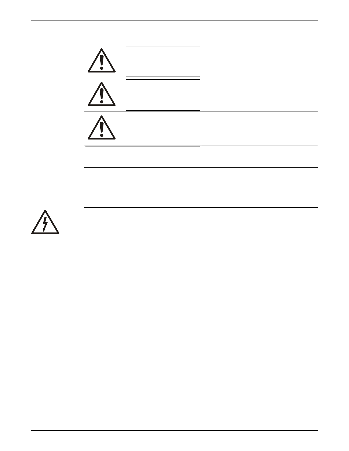
Hazard levels
Hazard level Indication
DANGER:
A hazardous situation which, if not avoided, will result in
death or serious injury
Introduction and Safety
Hazard categories
WARNING:
CAUTION:
NOTICE:
Hazard categories can either fall under hazard levels or let specific symbols replace the
ordinary hazard level symbols.
Electrical hazards are indicated by the following specific symbol:
Electrical Hazard:
These are examples of other categories that can occur. They fall under the ordinary
hazard levels and may use complementing symbols:
• Crush hazard
• Cutting hazard
• Arc flash hazard
A hazardous situation which, if not avoided, could result
in death or serious injury
A hazardous situation which, if not avoided, could result
in minor or moderate injury
• A potential situation which, if not avoided, could
result in undesirable conditions
• A practice not related to personal injury
User safety
General safety rules
These safety rules apply:
• Always keep the work area clean.
• Pay attention to the risks presented by gas and vapors in the work area.
• Avoid all electrical dangers. Pay attention to the risks of electric shock or arc flash
hazards.
• Always bear in mind the risk of drowning, electrical accidents, and burn injuries.
Safety equipment
Use safety equipment according to the company regulations. Use this safety equipment
within the work area:
• Hard hat
• Safety goggles, preferably with side shields
• Protective shoes
• Protective gloves
• Gas mask
PSE-800-M Low Water Cut-off Installation, Operation, and Maintenance Manual 3
Page 6

Introduction and Safety
• Hearing protection
• First-aid kit
• Safety devices
NOTICE:
Never operate a unit unless safety devices are installed. Also see specific information
about safety devices in other chapters of this manual.
Electrical connections
Electrical connections must be made by certified electricians in compliance with all
international, national, state, and local regulations. For more information about
requirements, see sections dealing specifically with electrical connections.
Product warranty
Coverage
Xylem undertakes to remedy defects in products from Xylem under these conditions:
• The faults are due to defects in design, materials, or workmanship.
• The faults are reported to a local sales and service representative within the warranty
period.
• The product is used only under the conditions that are described in this manual.
• The monitoring equipment that is incorporated in the product is correctly connected
and in use.
• All service and repair work that is done by Xylem authorized personnel.
• Genuine Xylem parts are used.
• Only Ex-approved spare parts and accessories that are authorized by an Ex-approved
Xylem representative are used in Ex-approved products.
Limitations
Warranty claim
The warranty does not cover defects that are caused by these situations:
Deficient maintenance
•
• Improper installation
• Modifications or changes to the product and installation that are made without
consulting a Xylem authorized representative
• Incorrectly executed repair work
• Normal wear and tear
Xylem assumes no liability for these situations:
• Bodily injuries
• Material damages
• Economic losses
Xylem products are high-quality products with expected reliable operation and long life.
However, should the need for a warranty claim arise, contact your local sales and service
representative.
4 PSE-800-M Low Water Cut-off Installation, Operation, and Maintenance Manual
Page 7

Product Description
3 42
1
General description
Description
The probe is a manual reset low water cut-off control. The control unit has a red LED light
to alert personnel to a low water condition and a green LED to indicate normal operation.
Lockout delay
When a low water condition occurs, the burner turns off and the red LED begins to blink.
When the water level is not restored to a level above the probe within 60 seconds, the
control locks out. Press the reset button when the water level is restored to a level above
the probe.
Power interruption
The control will automatically reset after a loss of power as long as there is water on the
probe before and after the power loss occurred.
CSD-1 code compliance
For manual reset units, when the control is in a low water condition and there is an
interruption of power the control remains in that condition when power is restored. Press
the reset button when the water level is restored to a level above the probe.
Product Description
NOTICE:
Flood hazard. Do not use manual reset models with automatic water feeders.
1. Test button
2. Power on LED, green
3. Reset button
4. Low water LED, red
Figure 1: Control unit
Operational specifications
Control unit ratings
Storage temperature -40°F to 135˚F (-40°F to 57˚C)
Ambient temperature 32°F to 120˚F (0°F to 49˚C)
Humidity 85% non-condensing
PSE-800-M Low Water Cut-off Installation, Operation, and Maintenance Manual 5
Page 8

1.31
(33)
1.56
(40)
2.13
(54)
3/4 NPT
1.31
(33)
3.06
(78)
1.56
(40)
3/4 NPT
Product Description
Probe specifications
Maximum steam pressure: 15 psi (1.0 kg/cm
Probe dimensions in inches (mm)
Figure 2: Standard probe
2
Figure 3: “U” probe
Electrical specifications
Ratings
Model Control Voltage Motor Switch rating Pilot rating
PSE-802–M-24 24 VAC N/A 50 VA
PSE-802–M-U-24
PSE-801–M-120 120 VAC 7.5 FLA 43.2 LRA 125 VA
PSE-801–M-U-120
Hertz
50/60
Control power consumption
• 1.7 VA at 24 VAC
• 3.6 VA at 120 VAC
Electrical enclosure rating
• NEMA 1 general purpose
Agency listings
6 PSE-800-M Low Water Cut-off Installation, Operation, and Maintenance Manual
Page 9

Installation
1
2
1
3
4
¼”
(6 mm)
¼”
(6 mm)
Determine location for the probe installation
DANGER:
Electrical hazard sufficient to kill. Always disconnect and lock out the power before you
service the unit.
NOTICE:
• Low water cut-off must be installed in series with all other limit and operating controls
on the boiler. Check for proper operation of all of the limit and operating controls
before leaving the site.
• All work must be performed by qualified personnel trained in the proper application,
installation, and maintenance of plumbing, steam and electrical equipment or systems
in accordance with all applicable codes and regulations.
Use the following criteria to locate a suitable position to install the probe .
• Install probe in a tapping on the boiler that is designated by the boiler manufacturer.
Review boiler IOMs or contact manufacturer for location of tapping.
• Probe must be installed below the location or level of the existing automatic reset low
water cut-off (LWCO). Installing the probe above this location could result in nuisance
shutdowns or lockouts.
• Install probe in a location above the minimum safe water level as designated by the
boiler manufacturer.
• Installing the probe in a location other than a tapping designated by the boiler
manufacturer could result in nuisance shutdowns of the burner.
• There must be at least 1/4 in of clearance between the end or sides of the probe and
the wall of any piping or fitting.
• Do not install the probe in any pipe extension that covers all or part of the probe rod.
Water that is retained in a pipe extension and touches the probe prevents the probe
from recognizing a low water condition. The burner will not shut off.
Installation
Install the probe
1. Apply a small amount of pipe sealant to the external threads (2) of the probe (1).
IMPORTANT: Do not use PTFE tape. Only use a pipe sealant.
2. Tighten the probe (1) into the tapped connection (3) to 47 ft·lb (64 N·m).
Be sure to align the probe so that the mounting screws (4) are in a horizontal position.
PSE-800-M Low Water Cut-off Installation, Operation, and Maintenance Manual 7
Page 10

5
4
6
4
6
1
7
8
9
1
10
11
Installation
Install the control housing
1. Loosen the screws that secure the cover (5) to the control housing about 1–1/2 turns.
Remove cover.
2. Loosen the probe mounting screws (4) 1–1/2 turns or 1/8” (3 mm).
3. Slip the control housing (6) over the two screws at a 20° angle.
4. Rotate the control housing (6) 20° counter-clockwise so that the slots in the control
base are under the screws heads.
5. Tighten the mounting screws to approximately 2 ft·lbs. (2.6 N·M)
Steps 2 and 3 Steps 4 and 5
Wire the probe to the control housing
1. Slip the ring terminal (7) followed by the lock washer (8) over the threaded end of the
probe (1).
2. Tighten the wingnut (9) onto the probe to 1/2 ft·lb (.65 N·m).
3. Connect the probe (1) to the wiring circuit by sliding the female quick-connect
terminal of the probe wire (10) onto the male spade terminal (11). The male spade
terminal is marked J1.
8 PSE-800-M Low Water Cut-off Installation, Operation, and Maintenance Manual
Page 11

Control to boiler wiring
1
2
3
WARNING:
• Fire hazard. Electrical wiring must have a rating of 167ºF (75ºC) if the liquid exceeds
180ºF (82ºC).
• When installing jumper wire make sure you are not introducing a second voltage
source into the burner circuit and thereby bypassing other safety, limit, and operating
controls.
Select a wiring method after reviewing the wiring diagrams and notes.
• Voltage of new manual reset LWCO must be the same as the existing automatic reset
LWCO.
• Make sure the Factory jumper bar is installed on the existing auto reset probe type
LWCO connecting terminals H and C. If there is no jumper bar connecting Terminals
H and C, then consult the factory to discuss wiring options.
• For Option B, the power to the automatic reset LWCO turns off when the new manual
reset LWCO detects a low water condition. The water feeder does not operate until
the new manual reset LWCO detects water on the probe.
• For options A and C, the power to the new manual reset LWCO turns off when the
existing auto reset LWCO detects a low water condition, reducing the chance of
nuisance lockouts. The water feeder continues to operate because there is still power
to the existing auto reset LWCO. Power to the new manual reset LWCO is restored
when the auto reset LWCO detects water on the probe.
Installation
Electrical conduit connections
• Connect electric conduit using knockouts provided.
• Follow accepted electrical practices for installation of
• Refer to and follow local codes and standards when selecting the types of electrical
fittings and conduit.
Wire connections to the terminal block
Use the following instructions for all wire connections to the terminal block.
1. Strip about 1/3” (8.5 mm) of insulation from the wire.
2. Loosen the terminal screw (2) but do not remove it.
3. Move the wire clamping plate (3) back until the plate touches the back side of the
screw head.
4. Insert the stripped end of the wire between the terminal block (1) and the wire
clamping plate (3).
5. Tighten the terminal screw (2).
fittings and connections.
Option A wiring
PSE-800-M Low Water Cut-off Installation, Operation, and Maintenance Manual 9
Voltage of the new manual reset LWCO is the same as the existing auto reset LWCO
Page 12

N H C W B
1
N H C W B
1
N H C W B
1
(L1)
(L1)
N H
120 VAC
2
3
N H C W B
1
(L1)
(L1)
N H
120 VAC
2
3
Installation
1. Remove existing wire from terminal B of existing Auto Reset LWCO and connect to
terminal B of new Manual Reset LWCO.
2. Connect new wire from terminal B of existing Auto Reset LWCO to terminal H of new
Manual Reset LWCO.
3. Connect new wire from terminal N of existing Auto Reset LWCO to terminal N of new
Manual Reset LWCO.
Existing wiring to boiler New wiring to boiler
1. Factory jumper bar
_ _ _ _ Dashed lines indicate existing wires.
_____ Solid lines indicate new wires.
Water feeder should be wired to existing Auto Reset LWCO. Wiring diagrams for the
water feeder can be found in the water feeder installation instruction manual.
Option B wiring
Wiring a new 120 V manual reset LWCO to a boiler. Burner circuit voltage could be 24 V
or 120 V. Existing LWCO could be either probe or
1. Remove the existing hot “H” wire from the service switch and the L1 connection on the
2. Connect a new hot “H” wire from the service switch to terminal H on the LWCO.
3. Connect a new hot “H” wire from terminal “B” on the LWCO to the L1 connection on
4. Connect a new wire to terminal “N” of the LWCO and splice it to the existing neutral
float type.
boiler.
the boiler.
“N” wire.
Existing wiring to boiler New wiring to boiler
10 PSE-800-M Low Water Cut-off Installation, Operation, and Maintenance Manual
1. Factory jumper bar
2. Boiler connections
3. Service switch
_ _ _ _ Dashed lines indicate existing wires.
Page 13

Option C wiring
1 2
3 4
TOP
2
3
4
N H C W B
1
1 2
3 4
TOP
2
3
4
Wiring a new manual reset LWCO to a boiler with a Model 67 LWCO. Voltage of the new
manual reset LWCO must be the same voltage as the burner circuit.
1. Remove existing wire from terminal 1 of the Model 67 LWCO and connect it to
2. Connect a new wire from terminal 1 of Model 67 LWCO to terminal H of the new
3. Connect a new wire to terminal N of new manual reset LWCO and splice it to the
Installation
_____ Solid lines indicate new wires.
Terminal B of the new manual reset LWCO.
manual reset LWCO.
existing neutral wire.
Existing wiring to boiler New wiring to boiler
1. Factory jumper bar
2. To burner
3. Neutral
4. Hot
_ _ _ _ Dashed lines indicate existing wires.
_____ Solid lines indicate new wires.
PSE-800-M Low Water Cut-off Installation, Operation, and Maintenance Manual 11
Page 14

Commissioning, Startup, Operation, and Shutdown
Commissioning, Startup, Operation,
and Shutdown
Start up the boiler
1. Before
2. Fill the boiler with water.
Test the probe
filling the system, turn on the electric power to the boiler.
a) Upon initial power up, the green and red lights will flash simultaneously four
times.
b) The green light will turn on and the red light will begin to flash.
c) After 60 seconds, the red light will stop flashing and will remain on.
d) The burner will never turn on as long as there is no water on the probe.
a) When water touches the probe, the green and red lights will remain on.
b) After depressing manual reset button, the green and red lights will flash four
times simultaneously.
c) The green light will then turn on and the red light will turn off.
d) The burner will turn on as long as there is water on the probe.
Drain water from the boiler.
a) The burner turns off and the Red light begins to flash when there is no water on
the probe.
b) After 60 seconds, the red light will stop flashing and will remain on.
IMPORTANT: If water returns to the level of the probe at any time while the red
light flashes, then the control automatically resets.
c) The control is now locked out. The manual reset button has to be depressed when
water touches the probe.
Test the manual reset button
1. Test the cycle by depressing and holding the test button. The burner turns off and the
red light begins to
2. Red light stops flashing and remains on after 60 seconds.
3. Control is now locked out and burner remains off when test button is released.
4. Depress manual reset button. Green and red lights flash simultaneously four times.
5. Green light turns on and red light turns off.
6. Burner turns on as long as there is water on the probe.
12 PSE-800-M Low Water Cut-off Installation, Operation, and Maintenance Manual
flash.
Page 15

Maintenance
Maintenance schedule
WARNING:
• Maintenance and service must be performed by skilled and qualified personnel only.
• Replace probe when PFA insulator is cracked or worn or probe is loose.
• Test the low water cut-off annually.
• Remove and inspect the self-cleaning probe every five years.
• Use a non-abrasive cloth and rinse with clean water when the probe requires
cleaning. Do not use sharp instruments to remove accumulations of rust or scale.
• Replace probe every ten years.
• Replace the low water cut-off control box every 15 years.
Maintenance
PSE-800-M Low Water Cut-off Installation, Operation, and Maintenance Manual 13
Page 16

Troubleshooting
Troubleshooting
Probe fails to operate
Perform the following diagnostic checks if the probe fails to operate as required:
1. Check that the water level in the boiler is at or above the level of the probe.
2. Recheck all wiring to ensure proper connections as specified in the wiring diagrams of
the boiler manufacturer or in this instruction manual.
3. Check to ensure that PTFE tape has not been used on the threaded connection of the
electrode to the boiler.
4. Some foaming is common in certain boilers. Refer to recommendations from the
boiler manufacturer for cleaning the boiler and piping when excessive foaming
occurs.
14 PSE-800-M Low Water Cut-off Installation, Operation, and Maintenance Manual
Page 17

Page 18

Page 19

Page 20

Xylem |’zīləm|
1) The tissue in plants that brings water upward from the roots
2) A leading global water technology company
We're 12,900 people unified in a common purpose: creating innovative
solutions to meet our world's water needs. Developing new technologies that
will improve the way water is used, conserved, and re-used in the future is central
to our work. We move, treat, analyze, and return water to the environment, and
we help people use water efficiently, in their homes, buildings, factories and
farms. In more than 150 countries, we have strong, long-standing relationships
with customers who know us for our powerful combination of leading product
brands and applications expertise, backed by a legacy of innovation.
For more information on how Xylem can help you, go to xyleminc.com
Xylem Inc.
8200 N. Austin Avenue
Morton Grove, IL 60053
Tel: 1-847-966-3700
Fax: 1-847-965-8379
www.mcdonnellmiller.com
211013_D_en.US_2014-01_IOM.PSE-800-M MM-289
Visit our Web site for the latest version of this document
and more information
The original instruction is in English. All non-English
instructions are translations of the original instruction.
©
2012 Xylem Inc
 Loading...