

Page 1

LISTED
INSTRUCTION MANUAL
210668B
Bell & Gossett®ZoneTrol II
Models Z-4B, Z-4M, Z-6B, Z-6M,
ZV-4B, ZV-4M, ZV-6B, ZV-6M
McDonnell & Miller ZoneSmart
U
L
®
C US
INSTALLER: PLEASE LEAVE THIS MANUAL FOR THE OWNER’S USE.
SAFETY
INSTRUCTION
This safety alert symbol will be used in this manual and on the
unit safety instructions decal to draw attention to safety related
instructions. When used, the safety alert symbol means ATTEN-
TION! BECOME ALERT! YOUR SAFETY IS INVOLVED!
FAILURE T
IN A SAFETY HAZARD.
NOTICE: This instruction manual is a supplement to, not a
replacement for Instruction Manual 210667. If you do
not have all manuals necessary for installation, please
contact the point of purchase or download the necessary
manuals at www.bellgossett.com.
O FOLLOW THE INSTRUCTIONS MAY RESULT
Models ZS-4B, ZS-4M, ZS-6B, ZS-6M,
ZSV-4B, ZSV-4M, ZSV-6B, ZSV-6M
™
™
Sensors Included
The Outdoor Temperature Sensor includes a
10 kΩ thermistor which provides an accurate
measurement of the outdoor temperature. The
sensor is protected by a white U.V. resistant
PVC plastic enclosure.
The Water Temperature Sensors have a zinc
sleeve for fast response and a wide operating
range. The sensors are supplied with 10 inches
(250mm) of two conductor wire.
DESCRIPTION
The outdoor reset modules are integrated into the
McDonnell & Miller ZoneSmart or Bell & Gossett ZoneTrol II
zone controllers. By monitoring outdoor temperature and
indexing the system supply water to the varying heatloss of
the building, the reset controllers minimize fuel consumption
while maximizing occupant comfort.
The Boiler Reset Control is designed to control a single
stage, non modulating heat source in order to provide outdoor
reset.
The Mix Reset Control is designed to control the supply water
temperature to a hydronic system in order to provide outdoor
reset or setpoint operation. The control uses a variable speed
injection pump to regulate the supply water temperature, while
protecting the boiler against flue gas condensation.
SENSOR INSTALLATION INSTRUCTIONS
Outdoor Air Temperature Sensor
• Remove the screw and pull the front cover off the sensor
enclosure.
• The sensor can either be mounted directly onto a wall or a
2" x 4" electrical box.
• When the sensor is wall mounted, the wiring should enter
through the back or bottom of the enclosure. Do not mount
the sensor with the conduit knockout facing upwards as
water could enter the enclosure and damage the sensor.
• In order to prevent heat transmitted through the wall from
affecting the sensor reading, it may be necessary to install
an insulating barrier behind the enclosure.
• The sensor should be mounted on a wall which best represents the heat load on the building (a northern wall for most
buildings and a southern facing wall for buildings with large
sout h f aci ng gla ss areas). The sensor should not be
exposed to heat sources such as ventilation or window
openings.
Page 2
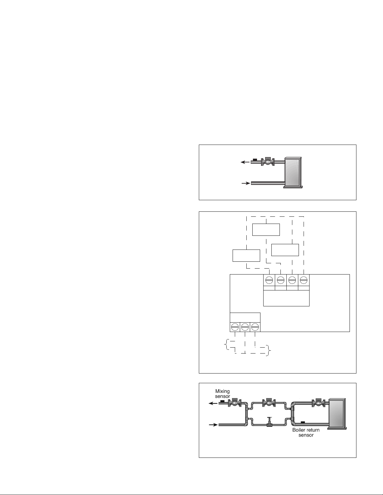
• The sensor should be installed at an elevation above the
Boiler supply
sensor
BOIL OUT
SUP
COM
Boiler Temp.
Sensor
Sensor
Temp. Sensor
Outdoor Temp.
Mix Supply
SYS/
BLR.
N
INJ/
MIX
120 VAC
To system
pump (if
applicable)
1/3 max.
HP*
To
injector
pump (if
applicable)
1.1A max.
ground that will prevent accidental damage or tampering.
• Connect 18 AWG or similar wire to the two terminals provided in the enclosure and run the wires from the sensor to
the control as shown in Figure 2. Do not run the wires parallel to telephone or power cables. If the sensor wires are
located in an area with strong sources of electromagnetic
interference (EMI), shielded cable or twisted pair should be
sed or the wires can be run in a grounded metal conduit. If
u
using shielded cable, the shield wire should be connected
to the Com Sen terminal on the control and not to earth
ground.
Replace the front cover of the sensor enclosure.
•
Water Temperature Sensor
• Water temperature sensors should be located as shown in
Figures 1 (boiler reset) & 3 (mix reset).
• Sensor wiring is per Figure 2.
• The Water Temperature Sensor can be strapped directly to
the pipe using the cable tie provided. Insulation should be
placed around the sensor to reduce the effect of air currents
on the sensor measurement.
• The Water Temperature Sensor should be placed downstream of a pump or after an elbow or similar fitting. This is
especially important if large diameter pipes are used as the
thermal stratification within the pipe can result in erroneous
sensor readings. Proper sensor location requires that the
fluid is thoroughly mixed within the pipe before it reaches
the sensor.
than the BOIL MIN setting while the boiler is firing, the controller reduces the output to the variable speed injection
pump. This limits the amount of cool return water to the boiler,
and allows the boiler temperature to recover.
Exercise: The controller has a built-in exercising function. If
the pump has not been operated at least once every 3 days,
the control turns on the output for 10 seconds. This minimizes
the possibility of the pump seizing during a long period of
nactivity.
i
Warm Weather Shutdown (WWSD)
When the outdoor air temperature rises above the WWSD setting, the controller turns on the WWSD segment in the display.
When the control is in Warm Weather Shut Down, the Mixing
Demand pointer is displayed, if there is a demand. However,
the control does not operate the heating system to satisfy this
demand.
Figure 1: Sensor Location for Boiler Reset
OPERATING SEQUENCE
Boiler Reset Control
The Boiler Reset Control operates a single on / off heat source
to control the supply water temperature to a hydronic system.
The supply water temperature is based on the current outdoor
air temperature and the Characterized Heating Curve settings.
Outdoor Reset: The controller calculates a supply temperature based on the current outdoor air temperature and the
Characterized Heating Curve settings. The burner on the boiler
is then cycled to maintain the water temperature required
based on the heating curve.
Warm Weather Shutdown: When the outdoor air temperature
rises above the WWSD setting, the controller turns on the
WWSD segment in the display. When the control is in Warm
Weather Shut Down, the Boiler Demand pointer is displayed, if
there is a demand. However, the control does not operate the
heating system to satisfy this demand.
Mix Reset Control
The Mix Reset Control uses a variable speed injection pump
to control the supply water temperature to a hydronic system.
The supply water temperature is based on either the current
outdoor temperature, or a fixed setpoint.
Outdoor Reset: The controller calculates a mixing supply
temperature based on the current outdoor air temperature and
the Characterized Heating Curve settings.
Variable Speed Injection: circulator is connected to the controller. The controller increases or decreases the power output
to a standard wet rotor circulator when there is a mixing
demand. The circulator speed varies to maintain the correct
mixed supply water temperature at the mix sensor. A visual
indication of the current variable speed output is displayed in
the LCD in the form of a horizontal bar graph.
Boiler Protection (BOIL MIN): The controller is capable of
providing boiler protection from cold mixing system return
water temperatures. If the boiler sensor temperature is cooler
Figure 2: Sensor and Mix Pump Wiring
Figure 3: Pump Terminology and Sensor Location
on systems using Mix or Injection Pump
*Do not exceed the maximum combined load.
Page 3

Boiler Reset Control Set-Up Parameters
ADJUST
ROOM
°
F
ADJUST
DSGN
OUTDR
°F
A
DJUST
DSGN
BOIL
°F
ADJUST
BOIL
°F
MIN
ADJUST
DIFF
BOIL
ADJUST
ADJUST
°F
Display Parameter Definition Range Notes Setting
Field
ROOM DESIGN The room design 35°F to 100°F If the original heating system design
TEMP temperature used (1°C to 37°C) criteria are unknown, the ROOM
in the original heat DESIGN TEMP should be set to the
loss calculation for estimated highest typical (non setthe building back) thermostat setting
OUTDOOR The outdoor design -60°F to +45F If the original heating system design
DESIGN TEMP temperature used (-51°C to 7°C) criteria are unknown, the OUTDOOR
in the original heat DESIGN TEMP should be set to the
loss calculation for estimated lowest expected outdoor
he building temperature based on geographical
t
location
BOILER DESIGN Supply water tem- 70°F to 210°F Recommended Settings
TEMP perature required (21°C to 93°C) High Mass Radiant (e.g., concrete):
to heat the building 120°F (49°C)
when outdoor Low Mass Radiant (e.g., wood floor):
temperature is equal 140°F (60°C)
OUTDOOR DESIGN Fancoil: 190°F (88°C)
TEMP Fin Tube Convector: 180°F (82°C)
Radiator: 160°F (71°C)
Baseboard: 150°F (66°C)
BOILER Minimum water OFF Recommended Settings
MINIMUM temperature to be 80°F to 180°F Cast iron boiler: 150°F
TEMP returned to boiler (27°C to 82°C) Copper tube boiler: 140°F
Condensing boiler: OFF
Electric boiler: OFF
Note: Refer to boiler installation
instructions to determine the minimum
allowable return temperature
BOILER The range of tem- ADJ The controller calculates a boiler
DIFFERENTIAL perature deviation 2°F to 42°F target temperature based on
TEMP allowed above and (1°C to 23°C) multiple variables. The BOILER
below boiler target DIFFERENTIAL TEMP is the range
temperature around the target temp in which the
supply temperature is allowed to float.
For example, with a target temperature
of 150°F and a BOILER DIFFERENTIAL
TEMP of 10°F, the supply temp will vary
between 145° and 155°F. Using the
Auto Differential (ADJ) setting is recommended for optimum performance
WARM Outdoor tempera- 35°F to 100°F When the outdoor temperature exceeds
WEATHER ture above which (1°C to 37°C) the WWSD setting, the controller will not
SHUTDOWN the controller will OFF enable the boiler. It is typical to set the
TEMP not activate the WWSD value equal to the ROOM
boiler DESIGN TEMP. The OFF setting defeats
the WWSD logic
ENGLISH/ Parameters to be °F or °C
METRIC displayed in
Farenheit or
Celsius
ESCAPE Exit set up menu — To escape the set up menu, press either
the or key
Page 4

Boiler Reset Controller Display Parameters
VIEW
VIEW
OUTDR
VIEW
OUTDR
VIEW
B
OIL
V
IEW
BOIL
ADJUST
ROOM
°F
ADJUST
DSGN
OUTDR
°F
Display Parameter Notes
OUTDOOR Current outdoor air temperature as measured by the outdoor sensor. This is also the
TEMP default display for the control
BOILER Current boiler supply water temperature as measured by the boiler sensor
TEMP
BOILER Target boiler supply is the temperature the control is currently trying to maintain at the
TARGET TEMP boiler sensor
Boiler Reset Controller Fault Messages
Display Fault Notes
EEPROM The control was unable to read a piece of information from its EEPROM. This error can
FAULT be caused by a noisy power source. The control will load the factory defaults and stop
OUTDOOR The control is no longer able to read the outdoor sensor due to a short circuit. In this
SENSOR case, the control assumes an outdoor temperature of 32°F (0°C) and continues operation.
SHORT Check wiring between outdoor sensor and control unit. Verify all connections and inspect
CIRCUIT wire insulation and sensor for damage. To clear the error message from the control after
OUTDOOR The control is no longer able to read the outdoor sensor due to an open circuit. In this
SENSOR OPEN case, the control assumes an outdoor temperature of 32°F (0°C) and continues operation.
CIRCUIT Check wiring between outdoor sensor and control unit. Verify all connections and inspect
BOILER The control is no longer able to read the boiler sensor due to a short circuit. In this
SENSOR case, if the BOIL MIN adjustment is set to OFF the control does not operate the Boiler
SHORT contact. If the BOIL MIN adjustment is not set to OFF and a boiler demand is present,
CIRCUIT the Boiler contact will operate for up to 10 minutes of a 20 minute cycle. Check wiring
BOILER The control is no longer able to read the boiler sensor due to a short circuit. In this
SENSOR case, if the BOIL MIN adjustment is set to OFF the control does not operate the Boiler
OPEN contact. If the BOIL MIN adjustment is not set to OFF and a boiler demand is present,
CIRCUIT the Boiler contact will operate for up to 10 minutes of a 20 minute cycle. Check wiring
operation until all the settings are verified
the sensor has been repaired, press the Item button
for broken wire or damaged sensor. To clear the error message from the control after
the sensor has been repaired, press the Item button
between outdoor sensor and control unit. Verify all connections and inspect wire
insulation and sensor for damage. To clear the error message from the control after
the sensor has been repaired, press the Item button
between outdoor sensor and control unit. Verify all connections and inspect wire
insulation and sensor for damage. To clear the error message from the control after
the sensor has been repaired, press the Item button
Mix Reset Control Set-Up Parameters
Display Parameter Definition Range Notes Setting
ROOM DESIGN The room design 35°F to 100°F If the original heating system design
TEMP temperature used (1°C to 37°C) criteria are unknown, the ROOM
OUTDOOR The outdoor design -60°F to +45F If the original heating system design
DESIGN TEMP temperature used (-51°C to 7°C) criteria are unknown, the OUTDOOR
Field
in the original heat DESIGN TEMP should be set to the
loss calculation for estimated highest typical (non setthe building back) thermostat setting
in the original heat DESIGN TEMP should be set to the
loss calculation for estimated lowest expected outdoor
the building temperature based on geographical
location
Page 5

Mix Reset Control Set-Up Parameters (continued)
ADJUST
BOIL
°F
MIN
ADJUST
°F
ADJUST
VIEW
VIEW
OUTDR
Display Parameter Definition Range Notes Setting
Field
MIX DESIGN MIX water tempera- 70°F to 220°F Recommended Settings
TEMP perature required (21°C to 93°C) High Mass Radiant (e.g., concrete):
to heat the building 120°F (49°C)
when outdoor Low Mass Radiant (e.g., wood floor):
temperature is equal 140°F (60°C)
UTDOOR DESIGN Fancoil: 190°F (88°C)
O
TEMP Fin Tube Convector: 180°F (82°C)
Radiator: 160°F (71°C)
Baseboard: 150°F (66°C)
OILER Minimum water OFF Recommended Settings
B
MINIMUM temperature to be 80°F to 180°F Cast iron boiler: 150°F
TEMP returned to boiler (27°C to 82°C) Copper tube boiler: 140°F
Condensing boiler: OFF
Electric boiler: OFF
Note: Refer to boiler installation
instructions to determine the minimum
allowable return temperature
WARM Outdoor tempera- 35°F to 100°F When the outdoor temperature exceeds
WEATHER ture above which (1°C to 37°C) the WWSD setting, the controller will not
SHUTDOWN the controller will OFF enable the boiler. It is typical to set the
TEMP not activate the WWSD value equal to the ROOM
boiler DESIGN TEMP. The OFF setting defeats
the WWSD logic
ENGLISH/ Parameters to be °F or °C
METRIC displayed in
Farenheit or
Celsius
ESCAPE Exit set up menu — To escape the set up menu, press either
the or key
Mix Reset Control Display Parameters
Display Parameter Notes
OUTDOOR Current outdoor air temperature as measured by the outdoor sensor. This is also the
TEMP default display for the control. (OUTDOOR DSGN ≠ OFF)
MIX Current mixed supply water temperature as measured by the mixing sensor
TEMP
MIX TARGET Target mixed supply is the temperature the control is currently trying to maintain at the
TEMP mixing sensor
BOILER Current boiler temperature as measured by the boiler sensor. (Boiler sensor is present)
TEMP
Mix Reset Fault Messages
Display Fault Notes
EEPROM The control was unable to read a piece of information from its EEPROM. This error can
FAULT be caused by a noisy power source. The control will load the factory defaults and stop
OUTDOOR The control is no longer able to read the outdoor sensor due to a short circuit. In this
SENSOR case, the control assumes an outdoor temperature of 32°F (0°C) and continues operation.
SHORT Check wiring between outdoor sensor and control unit. Verify all connections and inspect
CIRCUIT wire insulation and sensor for damage. To clear the error message from the control after
operation until all the settings are verified
the sensor has been repaired, press the Item button
Page 6

Mix Reset Fault Messages (continued)
Display Fault Notes
OUTDR
BOIL
BOIL
MIX
MIX
VIEW
OUTDOOR The control is no longer able to read the outdoor sensor due to an open circuit. In this
SENSOR OPEN case, the control assumes an outdoor temperature of 32°F (0°C) and continues operation.
CIRCUIT Check wiring between outdoor sensor and control unit. Verify all connections and inspect
for broken wire or damaged sensor. To clear the error message from the control after
the sensor has been repaired, press the Item button
VIEW
BOILER The control is no longer able to read the boiler sensor due to a short circuit. In this
SENSOR case, if the BOIL MIN adjustment is set to OFF the control does not operate the Boiler
SHORT contact. If the BOIL MIN adjustment is not set to OFF and a boiler demand is present,
CIRCUIT the Boiler contact will operate for up to 10 minutes of a 20 minute cycle. Check wiring
between outdoor sensor and control unit. Verify all connections and inspect wire
insulation and sensor for damage. To clear the error message from the control after
the sensor has been repaired, press the Item button
VIEW
BOILER The control is no longer able to read the boiler sensor due to a open circuit. In this
SENSOR case, if the BOIL MIN adjustment is set to OFF, the control does not operate the Boiler
OPEN contact. If the BOIL MIN adjustment is not set to OFF, and a boiler demand is present,
CIRCUIT the Boiler contact will operate for up to 10 minutes of a 20 minute cycle. Check wiring
between outdoor sensor and control unit. Verify all connections and inspect wire
insulation and sensor
for damage. To clear the error message from the co
the sensor has been repaired, press the Item button
VIEW
MIX SENSOR The control is no longer able to read the mixing sensor due to a short circuit. In this
SHORT CIRCUIT case, the control will operate the injection pump at a fized output as long as there is a
mixing demand. Check wiring between sensor and control unit. Verify all connections
and inspect wire insulation and sensor for damage. To clear the error message from the
control after the sensor has been repaired, press the Item button
VIEW
MIX SENSOR The control is no longer able to read the mixing sensor due to a open circuit. In this
OPEN CIRCUIT case, the control will operate the injection pump at a fized output as long as there is a
mixing demand. Check wiring between sensor and control unit. Verify all connections
and inspect wire insulation and sensor for damage. To clear the error message from the
control after the sensor has been repaired, press the Item button
ntrol after
Sensor Resistance Chart
Temperature Resistance Temperature Resistance Temperature Resistance Temperature Resistance
°F °C °F °C °F °C °F °C
-50 -46 490,813 20 -7 46,218 90 32 7,334 160 71 1,689
-45 -43 405,710 25 -4 39,913 95 35 6,532 165 74 1,538
-40 -40 336,606 30 -1 34,558 100 38 5,828 170 77 1,403
-35 -37 280,279 35 2 29,996 105 41 5,210 175 79 1,281
-30 -34 234,196 40 4 26,099 110 43 4,665 180 82 1,172
-25 -32 196,358 45 7 22,763 115 46 4,184 185 85 1,073
-20 -29 165,180 50 10 19,900 120 49 3,760 190 88 983
-15 -26 139,402 55 13 17,436 125 52 3,383 195 91 903
-10 -23 118,018 60 16 15,311 130 54 3,050 200 93 829
-5 -21 100,221 65 18 13,474 135 57 2,754 205 96 763
0 -18 85,362 70 21 11,883 140 60 2,490 210 99 703
5 -15 72,918 75 24 10,501 145 63 2,255 215 102 648
10 -12 62,465 80 27 9,299 150 66 2,045 220 104 598
15 -9 53,658 85 29 8,250 155 68 1,857 225 107 553
Xylem Inc.
8200 N. Austin Avenue
Morton Grove, Illinois 60053
Phone: (847) 966-3700
Fax: (847) 965-8379
www.xyleminc.com/brands/bellgossett
Bell & Gossett is a trademark of Xylem Inc. or one of its subsidiaries.
© 2012 Xylem Inc. 210668B May 2012
 Loading...