

Page 1
INSTRUCTION MANUAL
210667C
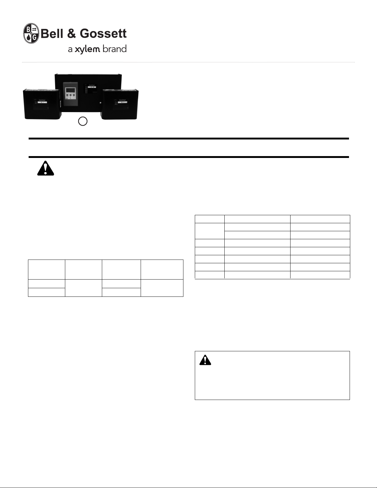
Bell & Gossett®ZoneTrol II
Models Z-4, Z-4B, Z-4M, Z-6, Z-6B, Z-6M
McDonnell & Miller ZoneSmart
U
L
®
C US
LISTED
INSTALLER: PLEASE LEAVE THIS MANUAL FOR THE OWNER’S USE.
SAFETY
INSTRUCTION
This safety alert symbol will be used in this manual and on the
unit safety instructions decal to draw attention to safety related
instructions. When used, the safety alert symbol means ATTEN-
TION! BECOME ALERT! YOUR SAFETY IS INVOLVED!
FAILURE TO FOLLOW THE INSTRUCTIONS MAY RESULT
IN A SAFETY HAZARD.
DESCRIPTION
The Bell & Gossett ZoneTrol II and McDonnell & Miller ZoneSmart Pump Controllers are
circulating pumps in hydronic systems.
Model Current Zones HP/Pump
Z-4 / ZS-4
Z-6 / ZS-6 6
20 amps maximum combined load.
T-stat Number of Max.
0.085
FEATURES
• Indicator lights visible without removing cover.
Power LED will illuminate when input power is applied to the
controller. Zone LEDs will illuminate when relay is energized.
• PRIORITY: This is typically used in domestic hot water
applications where it may be desirable to give hot water
production a priority over space heating requirements for a
certain period of time. Zone 1 is the priority zone and the
functionality is enabled via DIP switch 1. The priority timer is
selectable for 30 or 60 minutes, via DIP switch 3.
• PURGE: In normal operation, the last circulator will stop and
the boiler will shut down as soon as there is no longer a call
for heat. If the purge functionality is enabled via DIP switch
2, the boiler will shut down, but the circulator will continue
to run for 90 seconds to extract additional BTUs from the
boiler.
designed to control 120 VAC
Max.
4
Models ZS-4, ZS-4B, ZS-4M, ZS-6, ZS-6B, ZS-6M
1/3
™
™
• EXERCISE: When the exercise functionality is enabled via
DIP switch 4, each circulator will run for 10 seconds after
every 72 hours of inactivity. This prevents scale and other
deposits from accumulating around the rotating parts and
ensures a trouble free start up at the beginning of each
heating season.
DIP SWITCH SETTINGS
Switch ON OFF
1
2 Purge On Purge Off
3 Priority 30 minutes Priority 60 minutes
4 Exercise On Exercise Off
5 Reset Normal
6 Power Delay On Power Delay Off
Slave Master
Priority Off Priority On
OUTDOOR RESET
For controll ers with intergal outdoor reset con troller,
please refer to Instruction Manual 210668. This document
can be downloaded at www.bellgossett.com or
www.mcdonnellmiller.com.
MECHANICAL INSTALLATION INSTRUCTIONS
The pump controller should be securely mounted on a wall
near the pumps using four #8 screws (not included).
WARNING: Electrical Shock Hazard
Electrical connections are to be made by a qualified
electrician in accordance with all applicable codes, ordinances and good practices Disconnect and lock out the
power before making electrical connections. Failure to follow these instructions could result in serious personal injury
and/or death.
ELECTRICAL INSTAL LATION INSTRUCTIONS
1. Disc onnect the electr ica l supply to the pump bef ore
installing the controller.
2. Refer to the applicable wiring diagram
- Figure 1A: Cold Start Boiler
- Figure 1B: Tankless Coil
3. Verify that the circulator(s) do not exceed the electrical rating of the controller.
Page 2
Used only with optional reset
RW
LNG
4. Make electrical connections according to the applicable
wiring diagram. Run the pump power through the holes in
the controller chassis to the applicable L/N terminals. Keep
120 VAC and 24 VAC wiring separate. All 120 VAC wiring
should be 14 AWG (minimum) copper electrical wi re.
Perform all wiring in accordance with applicable codes.
5. If the priority function is to be enabled, the priority zone
(e.g., Domestic Hot Water) pump should be wired to the
Zone 1 L/N terminals.
6. Run the thermostat wires through the grommet(s) in the
controller chassis and connect to the appropriate R/W terminals. If the priority function is to be enabled, the priority
zone (e.g., Domestic Hot Water) T-Stat should be wired to
the Zone 1 R/W terminals. Keep 24 VAC wiring separate
from 120 VAC wiring.
NOTE: During the initial power-up
of the zone controller,
some “power stealing” thermostats may require up to 3
minutes to function properly. If the installation requires the
pump relays and X-X relay to be held open during this
power-up sequence, the installer can position DIP switch
6 to the “ON” position. This will cause the controller to
suspend relay operation during the thermostat power-up
period. Normal operation and cycling of the heating system
will resume after the 3 minute time period. This applies to
initial power-up only and does not affect normal system
operation.
EXPANSION
The 4 and 6 zone controllers can be connected together to
accommodate larger systems. A six conductor straight pinned
cable with two male RJ-11 terminations is required for connection of multiple controllers. This cable can be ordered from
your distributor as McDonnell & Miller part number 109454.
The “master” controller should have DIP switch 1 set to the
OFF position. “Slave” controllers should have DIP switch 1 set
to the ON position. If the Priority function is to be enabled
(e.g., domestic hot water production) Zone 1 on the Master
controller will be the priority zone.
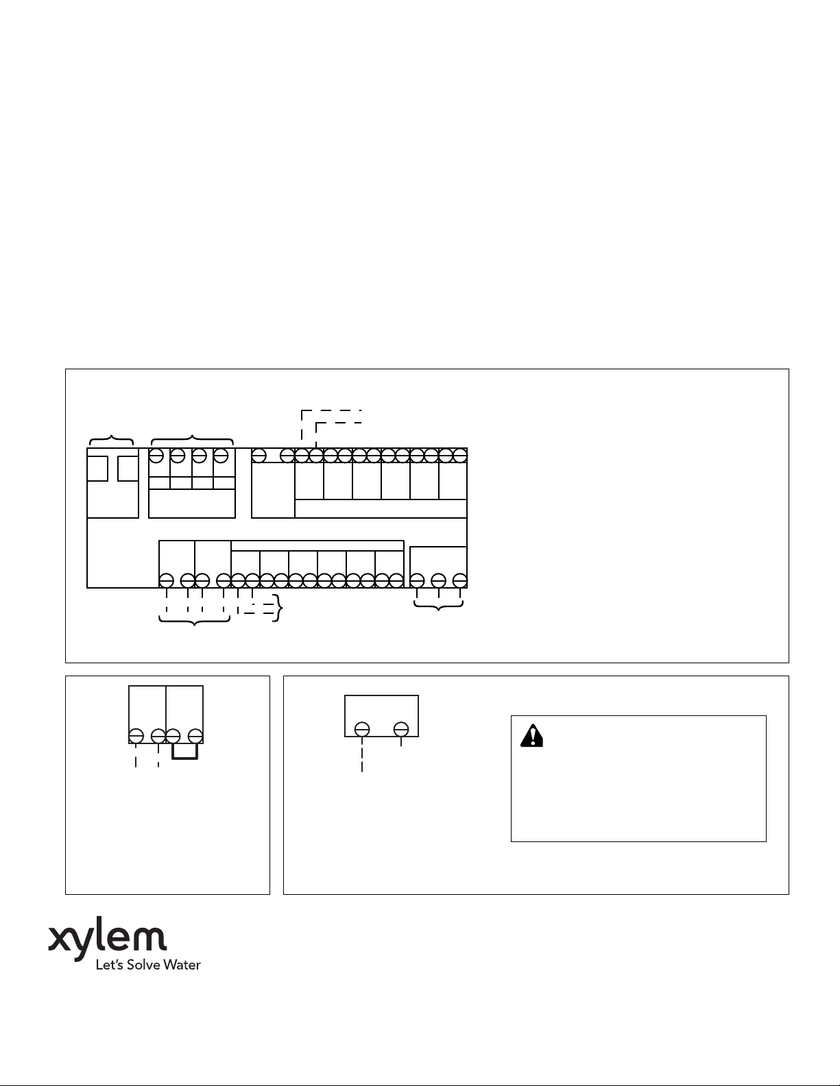
GENERAL WIRING DIAGRAM
Refer to Instruction Manual 210688 for units with outdoor reset controller.
For connection
of additional
controllers
EXPANSION
Figure 1A: Cold Start Boiler
control - refer to
instruction
manual 210668
for details
BOIL OUT SUP COM
INSOLATED END
SWITCH
X X ZC ZR
Refer to Fig 1A for cold start or
Fig. 1B for tankless coil application
X X ZC ZR
}
Jumper
To TT
on boiler
When a thermostat calls for heat,
the corresponding circulator will
start and the XX end switch will
close to enable the boiler.
RW
RW
ZONE 1
HN
24 VAC
ZONE 2LNZONE 3LNZONE 4LNZONE 5LNZONE 6
ZONE 1
LN
ZONE 2
CIRCULATORS
To zone
circulators
Figure 1B: Tankless Coil
When a thermostat calls for heat,
the corresponding circulator will
start when the boiler temperature
reaches the low limit setting.
}
RW
ZONE 3
THERMOSTATS
ZC ZR
To ZC on
aquastat
To
thermostats
RW
RW
ZONE 4
ZONE 5
LN
To ZR on
aquastat
ZONE 6
General Wiring Diagram
(6 zone controller shown)
120 VAC
Input Power
120/1/60
WARNING: Electrical Shock Hazard
When wiring per the Tankless Coil
Application, pump controller and boiler
aquastat must be on the same circuit and
have a common disconnect. Failure to follow these instructions may introduce a
secondary source of power resulting in
personal injury or death.
Xylem Inc.
8200 N. Austin Avenue
Morton Grove, Illinois 60053
Phone: (847) 966-3700
Fax: (847) 965-8379
www.xyleminc.com/brands/bellgossett
Bell & Gossett is a trademark of Xylem Inc. or one of its subsidiaries.
© 2012 Xylem Inc. 210667C May 2012
 Loading...