

Page 1
VARIABLE SPEED PUMPING SYSTEMS
INSTRUCTION MANUAL
VARIABLE SPEED PUMP CONTROLLER AND
INTEGRATED AJUSTABLE FREQUENCY DRIVE
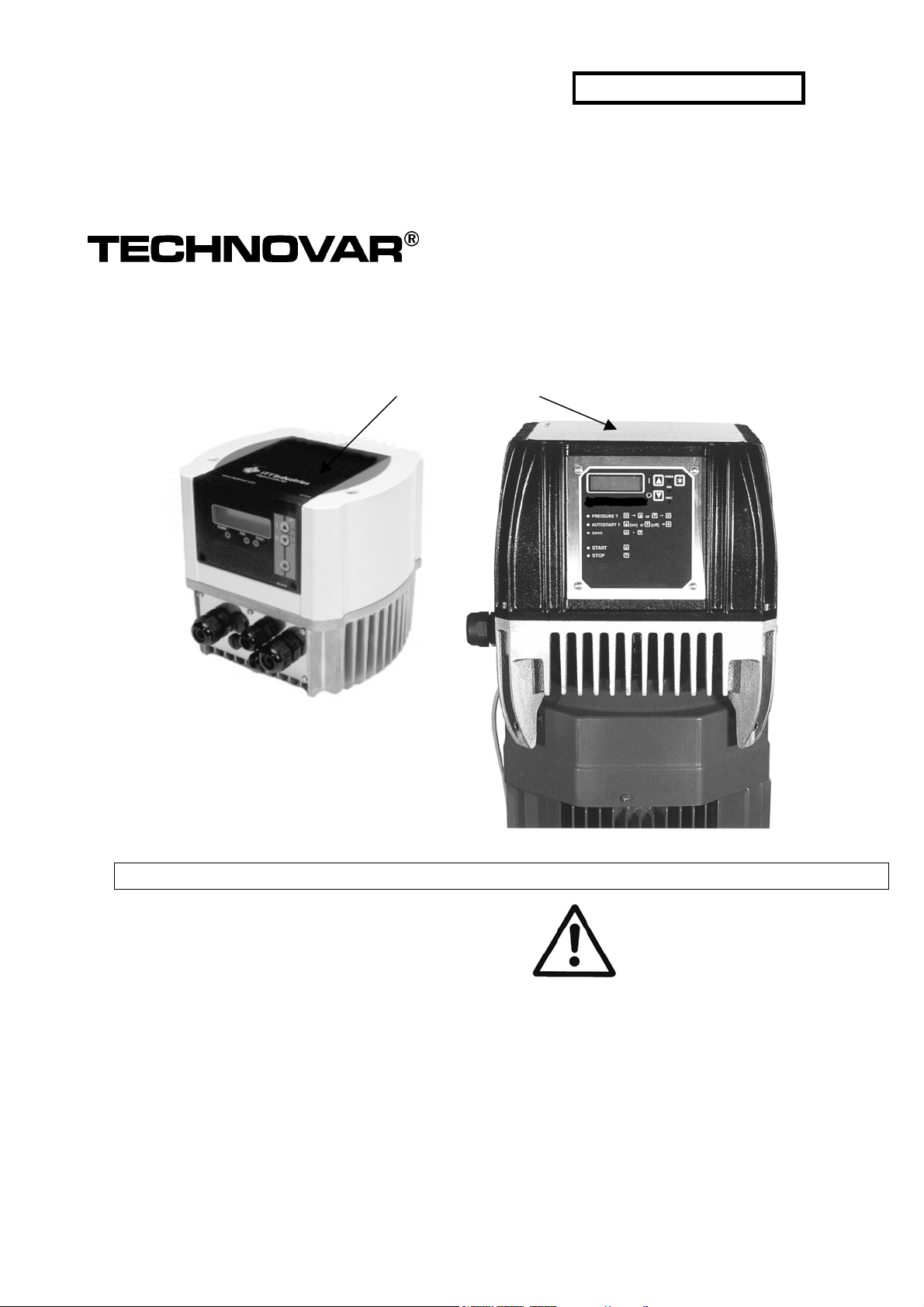
WARNING LABEL #S11550
HV 2.1-3.11
INSTALLED IN THIS LOCATION.
IF MISSING IT MUST BE
REPLACED.
INSTRUCTION MANUAL
210 980-2
HV 120-1-ENBG
26.03.2003
HV3.15-3.22
INSTALLER: PLEASE LEAVE THIS MANUAL FOR THE OWNER’S USE.
DESCRIPTION: Microprocessor based pump
controller and adjustable speed drive for variable
volume pumping systems. The controller consists
of the following components: microprocessor,
operator interface with alphanumeric display, and
membrane keypad.
OPERATIONAL LIMITS: See the control panel
nameplate for operating voltage, current draw, as
well as information on the equipment to be
connected to the control panel.
SAFETY INSTRUCTION
This safety alert symbol will be used in this
manual to draw attention to safety related
instructions. When used, the safety alert
symbol means ATTENTION!
BECOME ALERT! YOUR SAFETY IS INVOLVED!
FAILURE TO FOLLOW THE INSTRUCTION MAY
RESULT IN A SAFETY HAZARD!
Page 2

Operating Instruction
Index
1 Important safety instructions ........................................................................5
2 System Design................................................................................................ 7
3 Pressure tank ................................................................................................8
4 Technical Data - Frequency Inverter And General Data................................. 9
5 Dimensions and Weights .............................................................................11
6 Mounting the Technovar..............................................................................12
6.1Mounting the Technovar on the pump.................................................12
6.1.1 Components included............................................................................................ 12
6.1.2 Mounting .............................................................................................................. 13
6.1.3 Mounting the thermistor ....................................................................................... 23
6.2 Electric installation and wiring.............................................................24
6.2.1 Means of protection .............................................................................................. 24
6.2.2 Wiring the Technovar to the motor ....................................................................... 24
6.3 Main Voltage Terminals .......................................................................25
6.4 Control Terminals................................................................................. 26
6.4.1 Control terminals................................................................................................... 27
6.4.2 Dip-Switch on the controller board........................................................................ 28
6.4.3 Main parts from the control card........................................................................... 28
6.5 Front plate............................................................................................ 29
7 Language Selection...................................................................................... 30
8 Typical applications .....................................................................................31
8.1 Control ................................................................................................. 31
8.2 The Main Menu Setting........................................................................ 31
8.3 Single Pump – Pump Protection........................................................... 34
8.3.1 To set run out protection....................................................................................... 34
8.4 Single Pump – System Curve Compensation........................................ 36
8.4.1 Entering the compensation values......................................................................... 37
8.5 Multiple Pump - Constant Pressure and System Curve Compensation 38
9 Parameters of the main menu ..................................................................... 43
10 Settings at Secondary Menu.......................................................................46
10.1 JOG-MODE..........................................................................................46
10.2 Window - %........................................................................................ 47
10.3 Ramp Hysteresis ................................................................................. 47
10.4 Ramp 1: Fast running up time:........................................................... 47
10.5 Ramp 2: Fast running down time:...................................................... 47
10.6 Ramp 3: Slow running up time: ......................................................... 48
10.7 Ramp 4: Slow running down time: ....................................................48
2
Page 3

Operating Instruction
Ramp – Window.........................................................................................48
10.8 Maximum Frequency.......................................................................... 48
10.9 Minimum Frequency ..........................................................................49
10.10 Operation at the minimum frequency ............................................. 49
10.11 Delay time for shut off at minimum frequency ............................... 49
10.12 Boost ................................................................................................ 49
10.13 Sensor – Adjust................................................................................. 50
10.14 Sensor - Curve .................................................................................. 50
10.15 Setting of the measuring range ....................................................... 50
10.16 Operation Mode ............................................................................... 50
10.17 Control Response ............................................................................. 51
10.18 Start Value........................................................................................ 52
10.19 2nd Required Value............................................................................ 52
10.20 Configuration of 1st relay ................................................................. 53
10.21 Submenu Offset ............................................................................... 53
10.21.1 Source of the Offset input ................................................................................. 53
10.21.2 1
10.21.3 2
10.21.4 INTENSITY 1 ....................................................................................................... 54
10.21.5 INTENSITY 2 ....................................................................................................... 54
st
Offset level.................................................................................................... 53
nd
Offset level ................................................................................................... 54
10.22 Submenu Sequence control ............................................................. 54
10.22.1 Lift Value ........................................................................................................... 55
10.22.2 Fall Value ........................................................................................................... 55
10.22.3 Release frequency of the following controller.................................................... 56
10.22.4 Switch Interval................................................................................................... 56
10.22.5 Source of required value.................................................................................... 57
10.22.6 Synchronous Control ......................................................................................... 57
10.22.7 Pump status indication ...................................................................................... 58
10.22.8 Error Signals for Data Bus Interruptions............................................................. 58
10.23 Submenu - RS 485 Interface ............................................................. 59
10.23.1 Pump Address.................................................................................................... 59
10.23.2 ADC Reference................................................................................................... 59
10.24 Compensation Frequency................................................................. 59
10.25 Lift-Intensity.....................................................................................60
10.26 Analog - Output ............................................................................... 60
10.27 Unit...................................................................................................61
10.28 Automatic test run ........................................................................... 61
10.29 Submenu for manual test run.......................................................... 61
10.29.1 Activate manual test run.................................................................................... 61
10.29.2 Test Frequency................................................................................................... 61
10.29.3 Boost ................................................................................................................. 61
10.30 Submenu - Error ............................................................................... 62
10.30.1 Conveyor Limit................................................................................................... 62
10.30.2 Delay Time......................................................................................................... 62
3
Page 4

Operating Instruction
10.30.3 Automatic Error reset......................................................................................... 62
10.30.4 Erase Error memory ........................................................................................... 63
10.31 Operating Hours............................................................................... 63
10.32 Display - Contrast............................................................................. 63
10.33 Set Password .................................................................................... 63
10.34 Operating Lock .................................................................................63
10.35 Internal Heater ................................................................................. 63
10.36 Setting Default Values......................................................................64
10.36.1 Default Values Europe ....................................................................................... 64
10.36.2 Default Values USA............................................................................................ 64
10.37 Saving...............................................................................................64
11 Error Signals................................................................................................ 65
11.1 Low Water .......................................................................................... 65
11.2 Conveyor Control ...............................................................................65
11.3 Overheating – Motor .......................................................................... 65
11.4 Overheating – Inverter ....................................................................... 65
11.5 Over voltage.......................................................................................65
11.6 Under voltage..................................................................................... 66
11.7 Limit ................................................................................................... 66
11.8 Short Circuit ....................................................................................... 66
11.9 Overload............................................................................................. 66
11.10 Pressure Sensor Error I < 4 mA ...................................................... 66
11.11 Additional Error signals:................................................................... 67
12 RS 485 - Interface........................................................................................ 67
13 Auxiliary Texts.............................................................................................68
14 Maintenance ...............................................................................................73
14.1 Notes.................................................................................................. 73
Follow the Pump Operating and Maintenance Instructions
We reserve the right to alter specifications
4
Page 5

Operating Instruction
1 Important safety instructions
In addition to the instructions contained in these operating instructions please pay
attention to universal safety and accident prevention regulations.
The TECHNOVAR drive head must be disconnected from the power supply before any work
can be carried out in the electrical or mechanical part of the system.
Installation, maintenance and repair work may only be carried out by trained, skilled and
qualified personnel.
Unauthorized modifications or changes to the system make all guarantees null and void.
When in operation, the motor can be stopped by remote control, whereby the drive head and
the motor remain under voltage. For safety reasons, the unit has to be disconnected from the
power supply when carrying out work on the machinery as locking out the equipment by
switching off the release mechanism or set value cannot prevent accidental starting of the
motor.
When the drive head is connected to power supply, the components of the
power unit as well as certain components of the master control unit are also
connected to the power supply.
Touching these components seriously endangers life !
Before removing the frequency inverter cover the system must be
disconnected from the power supply. After switching off the power supply
wait at least 5 minutes before starting work on or in the TECHNOVAR drive
head (the capacitors in the intermediate circuit have to be discharged by the
installed discharge resistors first).
Voltages of up to 800 volts are possible (if there are faults it can be higher)
All work, carried out when the frequency inverter is open, may only be
performed by qualified authorized staff.
Furthermore, care must be taken not to short circuit the neighbouring
components when connecting the external control wires and that open
cable ends which are not in use are isolated.
5
Page 6

Operating Instruction
The TECHNOVAR drive head contains electronic safety devices which
switch off the control element in the event of faults, whereby the
motor has zero current but remains energized and comes to a halt. The
motor can also be halted by mechanical blocking. If it is switched off
electronically the motor is disconnected from the mains voltage
through the electronics of the frequency converter but is not potentialfree in the circuit.
In addition voltage fluctuations, especially power failures can cause the
system to switch off itself.
Repair of faults can cause the motor to start up again!
The system may only be put into operation when it has been earthened. In addition,
equipotential bonding of all pipes must be ensured.
Warns that failure to observe the precautions may cause electrical shock.
Failure to follow these instructions could result in serious personal injury or death.
Warns that failure to follow these instructions could result in serious personal
injury or death as well as property damage.
6
Page 7
Operating Instruction
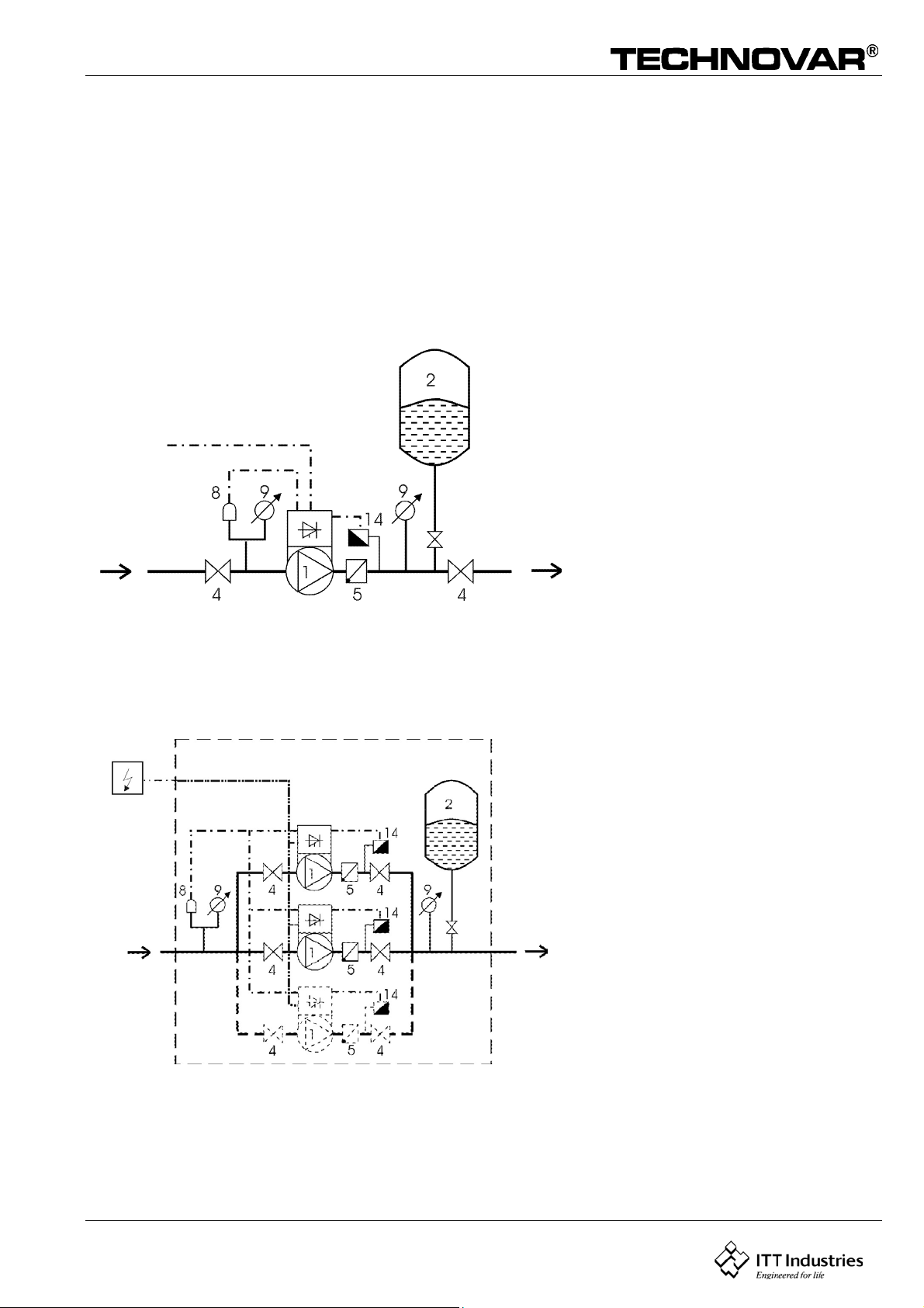
2 System Design
The following diagrams show typical single pump and multi-pump systems using the
Technovar control unit. Connection can be made directly to a water supply or water can be
drawn from a break tank or well. In the case of break tanks and wells, level switches, should
be used to shut down the pumps when water is low. In the direct connection, a pressure
switch on the suction side should be used.
(1) pump with drive head
(2) diaphragm tank
(3) distribution panel
(4) gate valve
(5) non return valve
Single Pump Layout
(8) incoming pressure control
(9) pressure gauge
(14) pressure transmitter
3
Multiple Pump Layout
7
Page 8
Operating Instruction
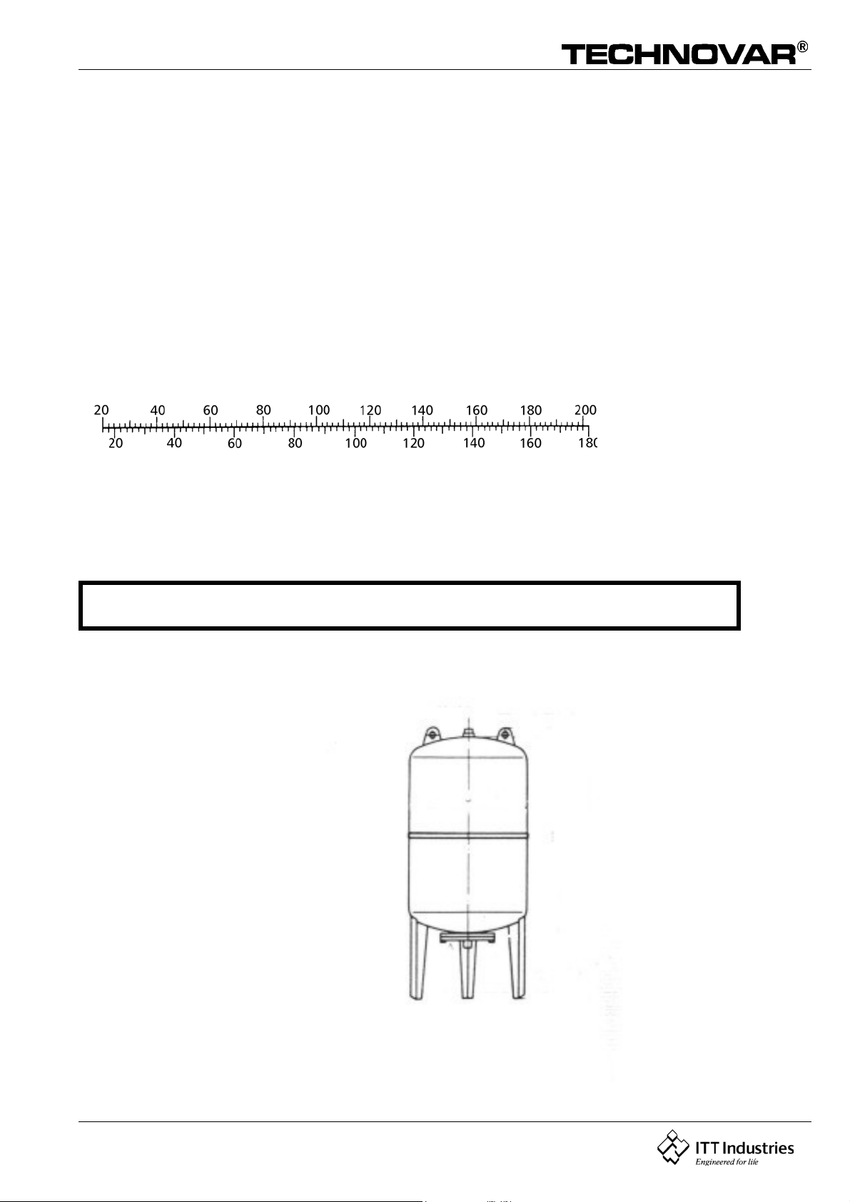
3 Pressure tank
A diaphragm pressure tank is used on the discharge side of the pump or pumps to maintain
pressure in the line when there is no demand. This will keep the pumps from continuing to
run. With the Technovar control unit, it is not necessary to have a large tank for supply
purposes.
In selecting a tank, make sure it is permit and suitable for systems pressure. The tank should
have a capacity of more than 10% of the maximum system flow rate g/min of one pump (also
in a multiple pump system!).
Pre charge the tank to the following:
Required pressure
Pre charge pressure (psi)
Note:
De-pressurize the tank prior to charging to ensure accuracy of the
pre-charged pressure.
8
Page 9

Operating Instruction
4 Technical Data - Frequency Inverter And General Data
TECHNOVAR Technovar
Supply Voltage
output to
the Motor
Model
No.
nominal
Horsepower
HV 2.1 2 7 A
HV 2.2 3 10 A
Max. Current
*1x220...240VAC ±15%
*1x220...240VAC ±15%
HV 3.2 3 5,7 A 3x380...460VAC ±15%
HV 3.3 4 7,3 A 3x380...460VAC ±15%
HV 3.4 5 9 A 3x380...460VAC ±15%
HV 3.5 7.5 13,5 A 3x380...460VAC ±15%
HV 3.7 10 17 A 3x380...460VAC ±15%
HV 3.11 15 23 A 3x380...460VAC ±15%
HV 3.15 20 30 A 3x380...460VAC ±15%
HV 3.18 25 37 A 3x380...460VAC ±15%
HV 3.22 30 43 A 3x380...460VAC ±15%
Note: Consult local authorities in your jurisdiction for fuse sizing.
* Output voltage is 3 phase and requires a motor suitable for 220-240V/3/60 input power
Mains frequency: 48....62 Hz
Max. frequency: See chapter 10.8
Min. frequency: 0 – f-max see chapter 10.9
Electrical efficiency: > 95%
Please
Note!
If the motor and control unit are assembled separately keep the
motor cable as short as possible in order to avoid electromagnetic
emissions and capacitive currents. The length may not exceed 66 m.
and a shielded cable has to be used.
Protection against: Short circuit, under- and over voltage, overheating of the electronics
(overload) and additional external protective functions via PTC (motor temperature) and
low water switch.
A mains filter is fitted to ensure interference immunity.
9
Page 10

Operating Instruction
The HV-series frequency converter complies with the general EMV provisions and has been
tested according to the following standards:
· Radio Interference Suppression EN 50082 Part 2
EN 55011
· High Frequency Field Interference ENV 50204
· Electrostatic Discharge EN 61000-4
Ambient temperature: +5° C ... +40°C
Storage temperature: -25° C ... +55° C (+70°C during max. 24 hours.)
Humidity: RH max. 50% at 40°C, Unlimited
RH max. 90% at 20°C, max. 30 days per year
75% average per year (Class F, DIN 40 040)
Condensation is not permitted !
Air pollution: The air may contain dry dust as found in workshops where there is
no excessive quantity of dust due to machines. Excessive amounts
of dust, acids, corrosive gases, salts etc. are not permitted
Altitude:: max. 3280 ft. above sea level At higher altitudes the max. available
power has to be reduced. Please ask the manufacturer for further
details.
Class of protection : IP 54 3.15-3.22
Nema 4 bis 3.11
10
Page 11
Operating Instruction
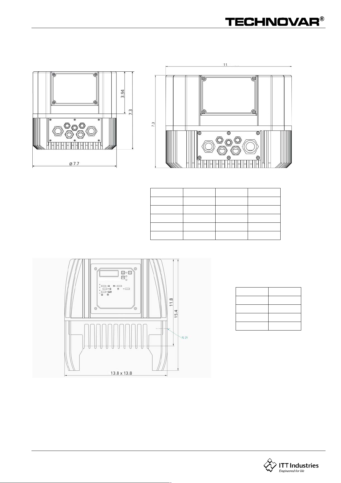
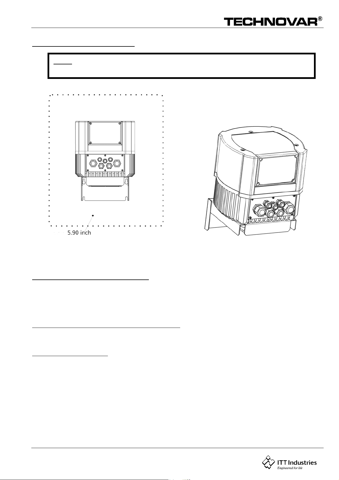
5 Dimensions and Weights
HV2.1/2.2/3.2/3.3/3.4 HV 3.5/3.7/3.11
Motorfancover max. 7.9 Ø
HV 3.15/ 3.18/ 3.22
Type: Weight: Type: Weight:
[lbs] [lbs]
HV 2.1 13 HV 3.4 13
HV 2.2 13 HV 3.5 22
HV 3.2 13 HV 3.7 22
HV 3.3 13 HV 3.11 22
Type Weight
[lbs]
HV3.15 64
HV3.18 64
HV3.22 64
all measurements in inches
Motorfancover max. 15.2 Ø
11
Page 12

Operating Instruction
6 Mounting the Technovar
6.1 Mounting the Technovar on the pump
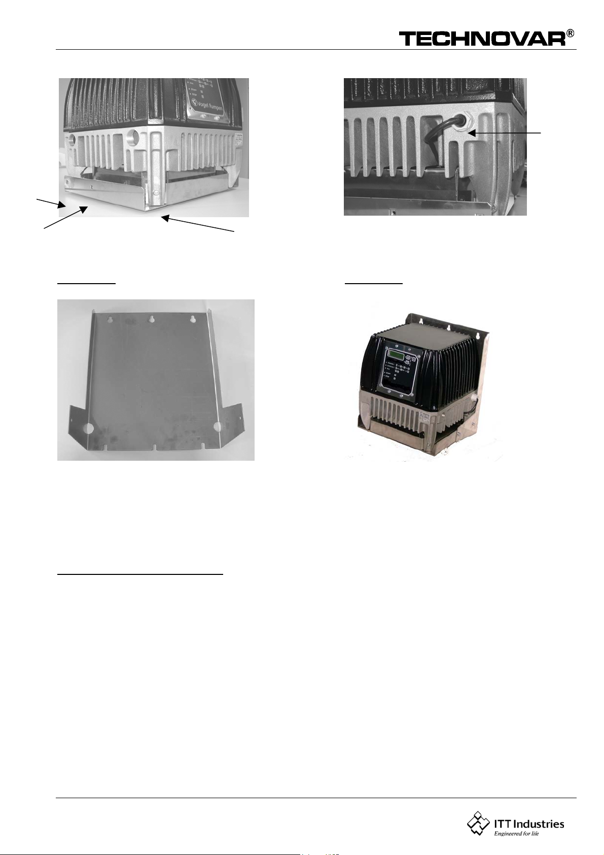
6.1.1 Components included
Thermal resistorScrew M5x90
cable gland
Mounting clamp
12
Page 13
Operating Instruction
y
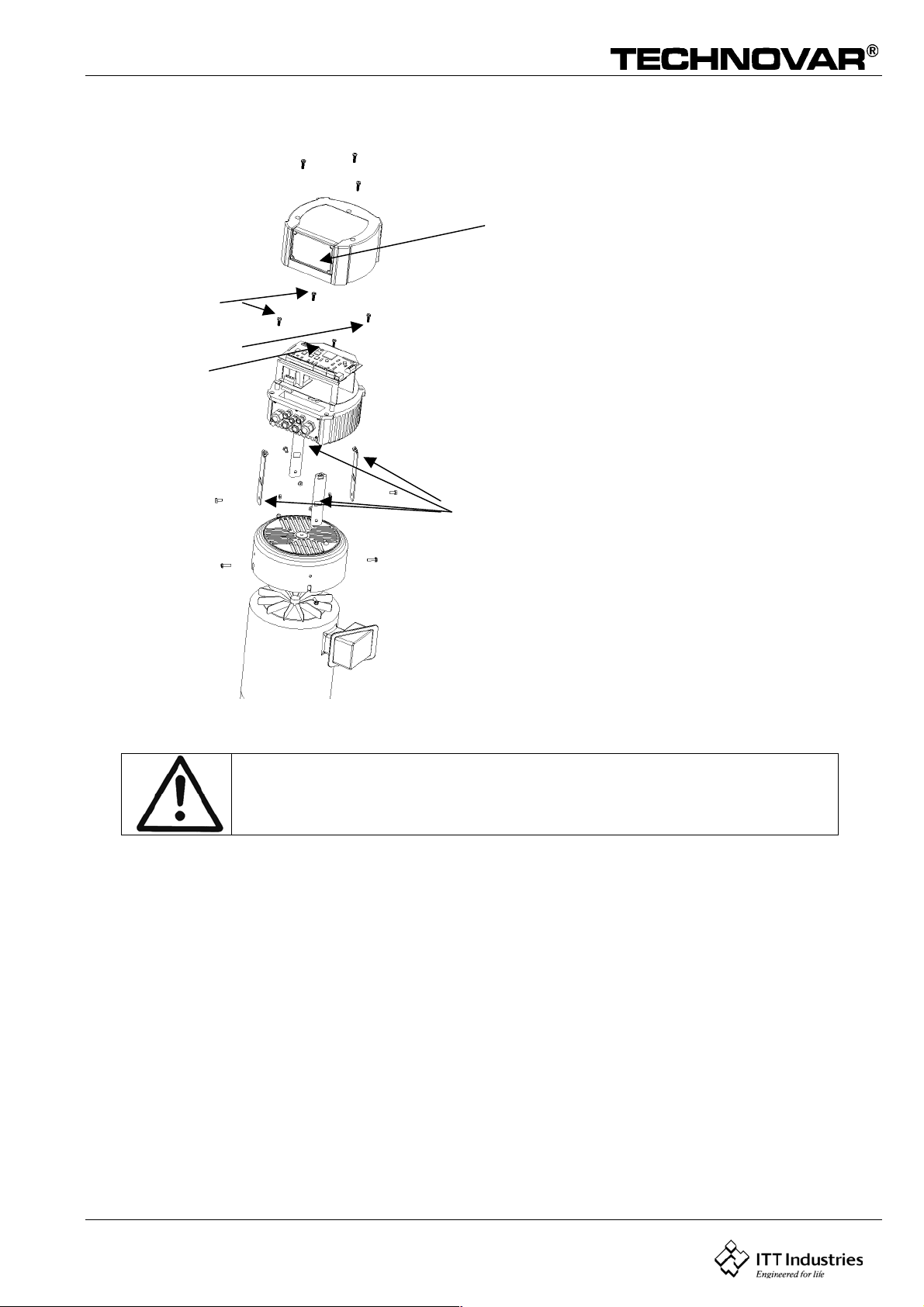
6.1.2 Mounting
HV2.1-3.11
Displa
changeable
to 180°
4 Screws
M5x90
Mounting:
u Remove the 3 screws from the
Technovar cover.
u Place the Technovar fan cover on
4 Mounting
clamps
the motor .
u Hang the 4 clamps by the
Motor fan cover and mounted
with the 4 screws.
u Mounted the cover with the
3 screws.
Don’t forget the gaskets for the 3 screws .
Ensure that there is no water on the unit before you open the cover.
Fix the display with the 4 Screws.
Thermistor
13
Page 14
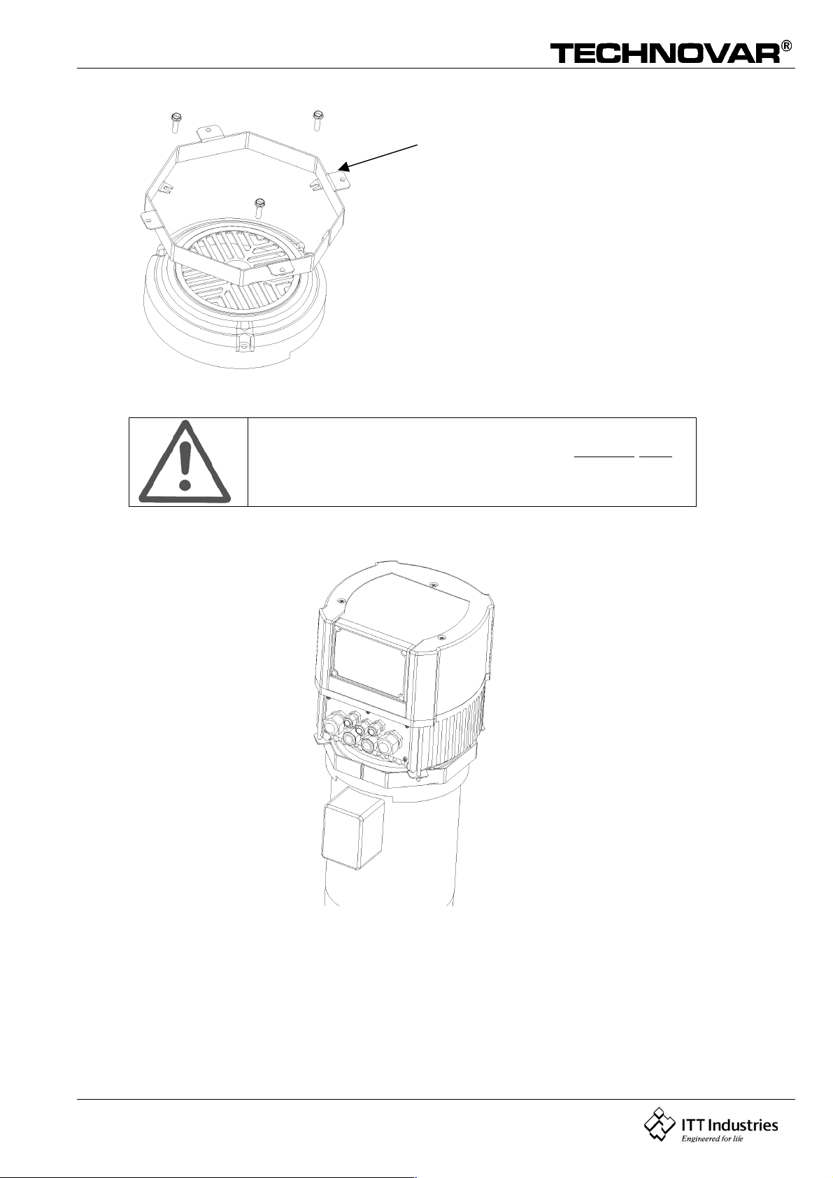
Operating Instruction
Mounting ring
If you use a motor with bis HV2,2kW, you have to use a
mounting ring.
14
Page 15
Operating Instruction
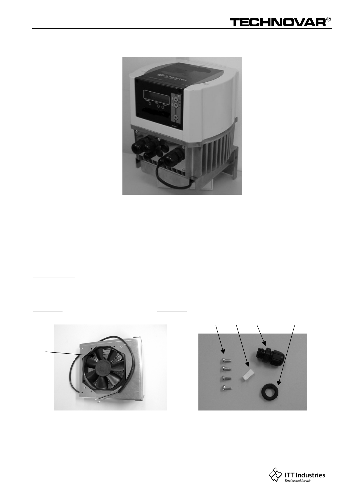
A
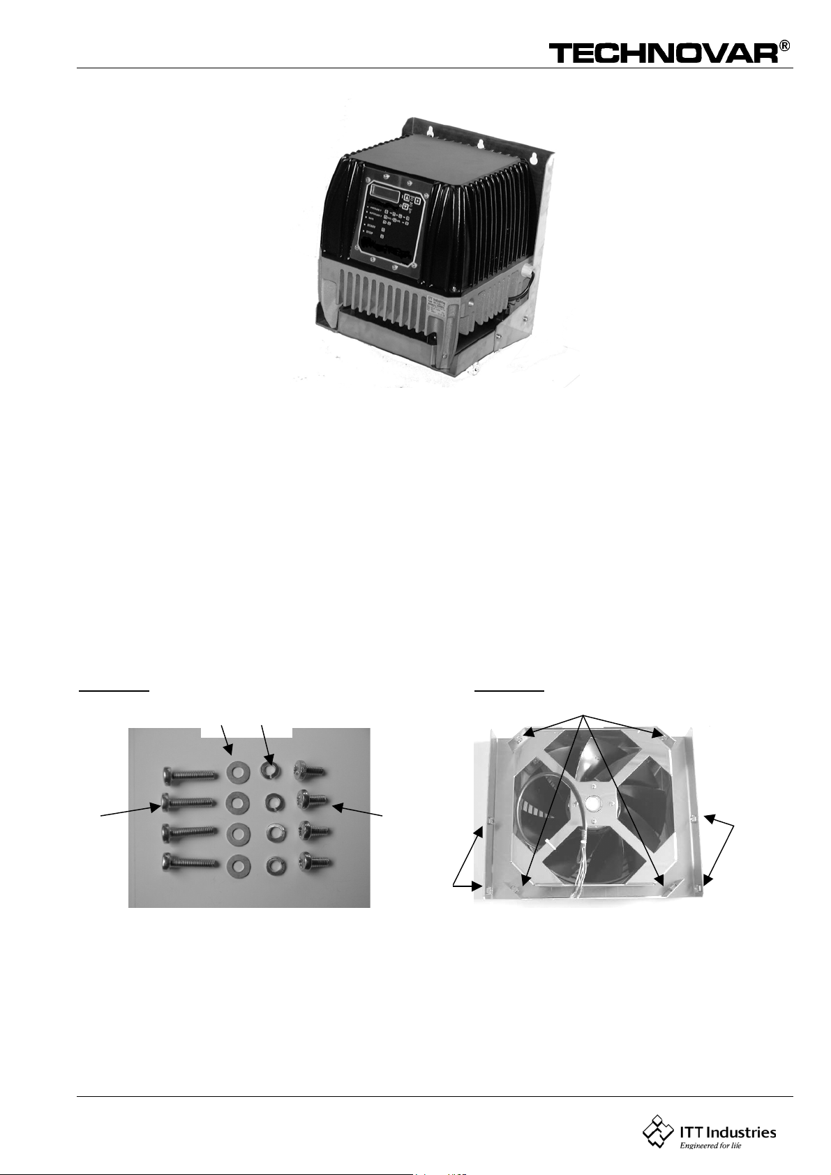
Wall mounting kit HV2.1-3.11
Included components for wallmounted kit HV2.1-3.11
1 mounting plate with fan Picture 1 A
4 M3x 8mm screws (self threading) for kit HV2.1-3.4 Picture 2 B
or M4x15mm screws (self threading) for kit HV3.5-3.11 Picture 2 B
1 Molex connector Mod. 6471-021 Picture 2 C
1 Cable gland M12x1,5 Picture 2 D
1 counter nut M12x1,5 Picture 2 E
not included: Dowels and mounting screws for mounting the kit on the wall.
Recommended diameter for this screws: Æ 5-6mm for kit HV2.1-3.4
Æ 6-8mm for kit HV3.5-3.11
Picture 1 Picture 2
BCD E
15
Page 16
Operating Instruction
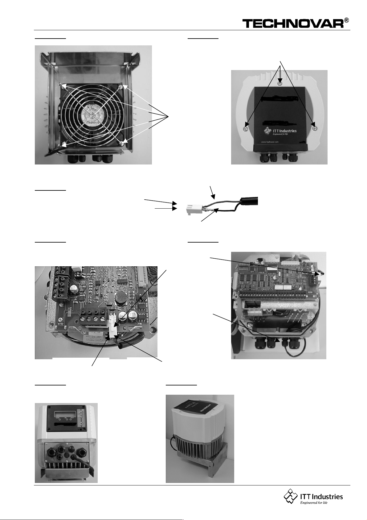
Picture 3 Picture 4
Screw M3x8mm or
M4x15mm
(self threading)
Open
Picture 5
red
+ plus pole
black
Picture 6 Picture 7
Molex connector
cable gland for
fan cable
plus pole/ red
Black / minus
Picture 8 Picture 9
16
Page 17
Operating Instruction
Free space for wallmounting
Note: You have to leave a free space in front of the Technovar for
configuration and for dismounting the cover.
free space required for cooling and mounting
MOUNTING INSTRUCTIONS
BEFORE REMOVING THE FREQUENCY INVERTER COVER THE SYSTEM MUST BE DIS-CONNECTED
FROM THE POWER SUPPLY. AFTER SWITCHING OFF THE POWER SUPPLY WAIT AT LEAST 5
MINUTES BEFORE STARTING WORK ON OR IN THE TECHNOVAR DRIVE HEAD.
Mounting the mounting plate on the HV 2.1-3.11
Place the heat sink of the Technovar on the mounting plate and fix them together by using the 4 self
threading M3x8mm respective M4x15mm screws (Picture 3).
Connecting the fan-cable
Remove the 3 screws holding the top cover of the Technovar and lift it carefully (picture 4).
NOTE: Take care with the connection cable to the display and the Ground-cable!
Left the cover aside.
Mount the included cable gland (Picture 2D/2E) on the cover plate and put the cable through the cable
gland. (Picture 7).
Connect the fan cable with the Molex connector (Picture 5) and then plug it into the right connection
on the control card (Picture 6).
NOTE: Take care of at the correct polarity: Red cable – plus pole
Black cable – minus pole
Fix the length of the cable inside the Technovar and tighten the cable gland to have ensure the IP55
class of protection.
17
Page 18
Operating Instruction
Afterwards replace the top cover and be careful with the connection cable to the display and the
Earth-cable. At last fix the 3 screws of the top cover.
In Pictures 8 and 9 you can see the Technovar with the mounted wallmounting-kit.
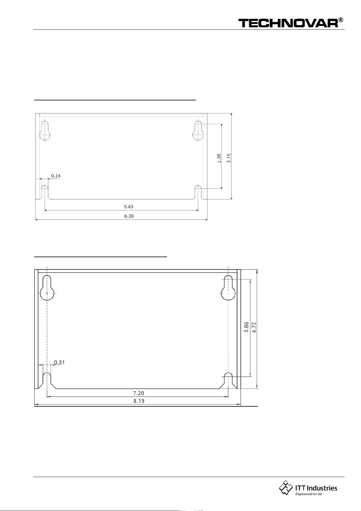
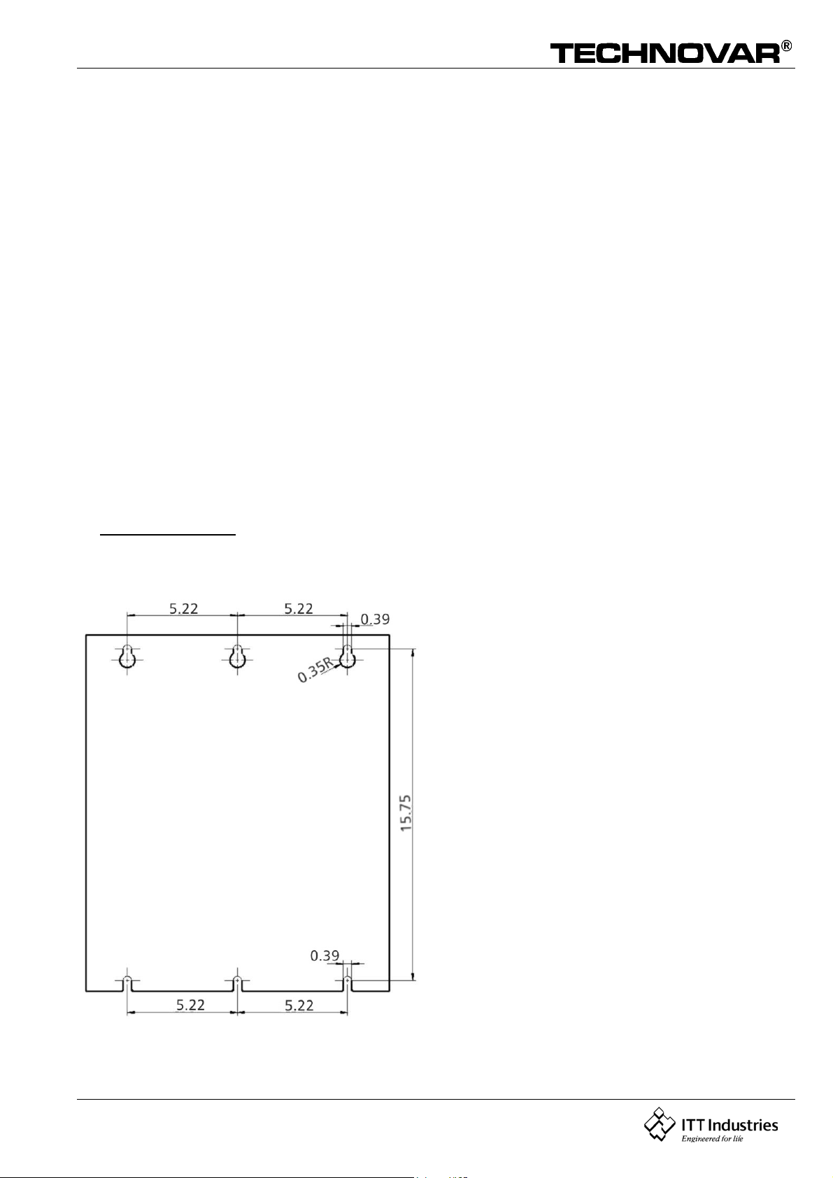
Mark the 4 holes according to the dimension drawing (see next page) on the wall and drill it with a
drilling machine. Mount the whole Technovar unit on the wall by using suitable screws.
Dimension drawing (HV2.1-3.4) (inches)
Dimension drawing (HV3.5-3.11)
18
Page 19
Operating Instruction
A
Wall mounting – kit 15/22kW
Included Components for wallmounted kit
4 long screw M6x25 Picture 1 A
4 washer Picture 1 B
4 short screw M6x12 Picture 1 C
4 washer Picture 1 D
1 AC-fan incl. connection cable Picture 2
1 fan board incl. 3 fuses T 1A/500V Picture 3 and 3 G
2 cable connector Picture 7
1 2 wire cable with connector Picture 7 and 8
1 cable gland for fan-cable Picture 12
1 wallmounted component Picture 13
Picture 1 Picture 2
B D
C
F
E
F
19
Page 20
Operating Instruction
G
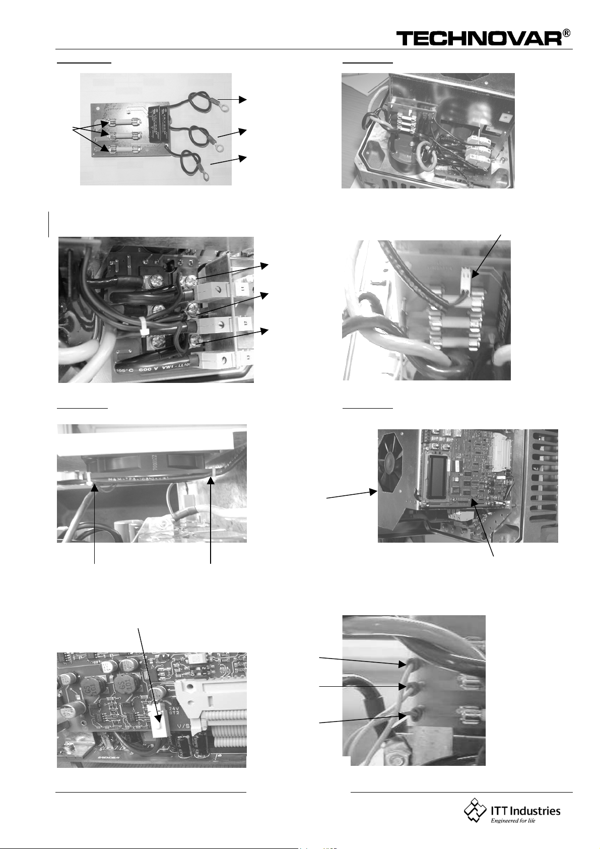
Picture 3 Picture 4
L3
L2
L1
Picture 5 Picture 6
L1
L2
L3
Picture 7 Picture 8
Picture 9 Picture 10
U2
V2
W2
20
Page 21
Operating Instruction
Picture 11 Picture 12
12
Picture 13 Picture 14
Mounting the wallmounted kit on the Technovar
BEFORE REMOVING THE FREQUENCY INVERTER COVER THE SYSTEM MUST BE DIS-CONNECTED
FROM THE POWER SUPPLY. AFTER SWITCHING OFF THE POWER SUPPLY WAIT AT LEAST 5
MINUTES BEFORE STARTING WORK ON OR IN THE TECHNOVAR DRIVE HEAD.
Mounting the fan-board
Loosen the 4 main screws from the Technovar cover and also the 8 screws holding the
control-card.
Then remove the Technovar cover carefully. (Take care with the control-card and the GNDCable.)
Picture 3 shows you the fan-board (incl. the 3 fuses 1A/500V- picture 3/G) that you can fix
with the 3 plastic-distances in the 3 holes which are made for. (Picture 4)
The power supply for the fan-board comes from the connections L1, L2, L3 on the primaryside from the rectifier-board.
Please fasten the connection screw as well and connect the right cable with the right
connection
Compare the cable number and the connection number. (Picture 5).
Connecting the control-cable
21
Page 22
Operating Instruction
Connect the included 2-wire.black cable with the fan-board (Picture 6) an take it upside to
the internal fan. Then place the cable beside the internal fan and fix it with the two cableconnectors which are shown in Picture 7.
Next put the cable through the hole at the front of the Technovar and pull it below the
control card at the bottom (Picture 8).
On the frontside of the control-card is an connector for plug in the control cable what you see
in Picture 9.
Mounting the fan on the Technovar
Place the Technovar at the AC-fan that you can see the LCD-Display at the front and the
pieces for the wallmounted component are on the side (Picture 11).
Then put the fan-cable through the hole and fix it with the included cable gland from picture
12. Look that the cable goes between the heat sink and isn´t fixed from it (Picture 12).
Connect the fan-cable at the connection clamps U2, V2, W2 on the fan board and screw the
GND-cable with the GND screw (Picture 10).
Next take the four long screws M6x25mm and the lock washers (see picture 1/A and B) and fix
the Technovar on the AC-fan with the nuts you can see in picture 2/E.
At least put the wall mounted component (Picture 13) behind the Technovar and fix this 2
components with the four short screws M6x12mm and the lock washers (see Picture 1/C and
D) what you see in picture 14.
!! PLEASE NOTE: The fan is only running with the TECHNOVAR (Run Signal).
Connect the fan cable so that the fan can blow from the carriersheed through the heat sink.
Dimension drawing
22
Page 23
Operating Instruction
k
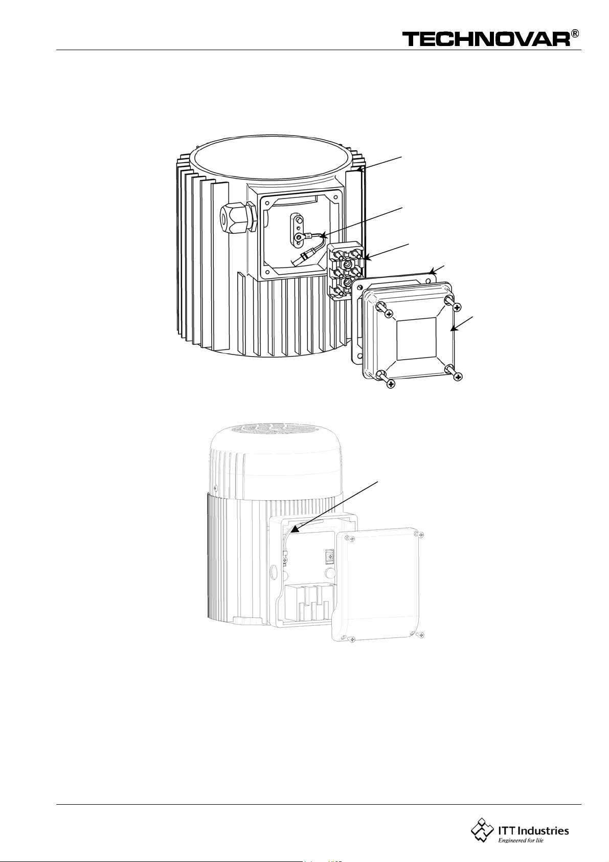
6.1.3 Mounting the thermistor
Variant A:
motor
thermistor
terminal bloc
rubber gasket
cover of the
conduit box
Variant B:
Thermistor
1. Open the cover of the conduit box and remove also the terminal block inside.
2. Fix the thermistor (Variant A or B)
3. Electrical connection of the motor cables see chapter 6.2.
4. Electrical connection to the Technovar see chapter 6.2
23
Page 24

Operating Instruction
6.2 Electric installation and wiring
6.2.1 Means of protection
Ask your power supply company which means of protection are required.
Applicable: AC and DC current-operated circuit breaker (FI), TN systems, protective
circuits.
When using a FI protection switch, make sure that it also releases in the event of
a DC fault, use for each Technovar a separate FI-switch!
6.2.2 Wiring the Technovar to the motor
Remove the 3 screws holding the top cover of the Technovar. Lift off the top carefully, take
off the connection cable to the display carefully remove the ground screw and left aside.
On the next page you can see:
(1) control card with all terminals for the control signals and the RS485 interface
(2) main card with all power components and terminals for power supply and motor
connections
24
Page 25

Operating Instruction
6.3 Main Voltage Terminals
HV2.1 / HV2.2
RS485 interface
Control terminals
Power supply
1x230 VAC
Motor connection
HV 3.2 – 3.11
RS485 interface
Control terminals
Motor connection
Power supply
3x400 VAC
HV 3.15/ 3.18/ 3.22
supply cable
The main power cable is connected to the terminals labeled L1, N for the 1x230 VAC, single
phase unit or L1, L2, L3 for the 3x400VAC, three phase unit.
RS485 interface
Control
terminals
Motor connection
Power supply
3x400 VAC
25
Page 26

Operating Instruction
6.4 Control Terminals
All externally used cables have to be shielded. Do not connect the ground of the electronic
components to other potentials (all electronic ground and GND of the RS 485-interface are
connected together internally).
For external off/on switches, contacts suitable for switching <10 VDC are necessary.
If unshielded control cables are used, signal interference may occur and interfere with
the function of the inverter.
Terminal:
Terminal:
(for dry 2 Fault signal relay CC max. 250VAC 1A free of inductivity
Contacts) 3 Fault signal relay NO max. 250VAC 1A free of inductivity
X1/ 1 GND
2 Actual value input 4...20mA, 50 Ohm load resistance
3 Power supply for external control 15VDC, max. 100mA
4GND
5 External on/off (release) Ri=10kOhm, 5 Volt DC
(gold plated contact necessary!)
6GND
7 Low water; Ri=10kOhm, 5 Volt DC
(e.g. incoming pressure switch or water level switch)
8 Thermo switch or PTC (in motor terminal box) Ri=10k, 5 VDC
9 Thermo switch or PTC
10 GND
11 Analog output 0...10 V, max. 2mA
12 Current signal input 4...20mA
13 Voltage signal input 0....10V or 2......10V
14 Digital input
X2/ 1 Fault signal relay NC max. 250VAC 1A free of inductivity
4 Pump operation
signal relay
5 Pump operation
signal relay
6 Pump operation
signal relay
NC max. 250VAC 1A free of inductivity
CC max. 250VAC 1A free of inductivity
NO max. 250VAC 1A free of inductivity
Terminal:
!! Fault relay (X2/2 - X2/3) is closed, when there is no error!!
X5-6/ 1 RS 485 SIO - LOW
2 RS 485 SIO + HIGH
3RS 485 GND
4 RS 485 + 5 VDC max. 20mA out
For supply of external interface
converter
26
Page 27

Operating Instruction
6.4.1 Control terminals
When connecting the variable speed pumps (max. 4 pumps) via the interface RS 485, the
terminals X5/1/2/3 or X6/1/2/3 of each Technovar are to be connected together by means of a
shielded cable and programmed accordingly (* Programming Sequential Operations).
27
Page 28

Operating Instruction
6.4.2 Dip-Switch on the controller board
SW4: DIP-Switch to select the switching frequency
!!Attention!!
SW4 Switching frequency
12
OFF OFF 8kHz (standard)
ON OFF 5kHz
OFF ON 4kHz
ON ON 2.5kHz
Before switching, disconnect the power supply, otherwise the
Technovar could be destroyed.
6.4.3 Main parts from the control card
Pin connection
(to Display)
40 pin connection
(to power board)
Dip-switch
24V output
(max. 800mA)
for external fan
Main supply
3x400 V
Control terminal
blocks
28
RS-485 terminals
Motor connection
Page 29

Operating Instruction
HV 3.15/ 3.18/ 3.22
Dip-switch
LCD
24V output
(max. 1A) for
external fan
Push buttons RS-485
terminals
Control terminal blocks
40 pin connection
(to power board)
6.5 Front plate
HV3.15/ 3.18/ 3.22
29
Page 30

Operating Instruction
HV 2.1-3.11
Power Run Fault
ON
OFF
Select
7 Language Selection
The information on the display can be called up in German, English, Italian, French, Spanish,
Portuguese or Dutch.
To select the desired language proceed as follows:
Briefly press + simultaneously (in 1st display); Þ the actual language will now appear
in the second line and the desired language can be selected with the button or . After
the language has been selected, press button briefly and the first menu window of the
main window will appear again. If only the language is changed it is not necessary to SAVE.
30
Page 31

Operating Instruction
8 Typical applications
8.1 Control
By means of the built-in Technovar controller acc. to constant pressure by pressure
transmitter and/or acc. to constant flow by flow-meter or orifice plate with differential
pressure transmitter and differential pressure transmitter or - if required - acc. to external
manual control by reference 4 - 20 mA DC (only for special applications).
8.2 The Main Menu Setting
There are ten display screens in the main menu which will allow you set the required system
pressure, save it, and turn the system on. Several of these display screens were already used
during the test run. After power has been turned on, the “Power on” light should illuminate
and the display should show “No Autostart – disable inverter”.
Instructions:
Check the green POWER light NO Autostart
disable inverter
Press the button to advance the display to INVERTER STOP
ON -> START
Press to advance the display to
REQUIRED VALUE
Set the desired set pressure with either or . If several pumps are connected via the RS485 interface, one pump must be ready for operation when the set pressure is changed,
otherwise the set value will not be accepted by the follow-up pumps. Afterwards the new
required pressure has to be saved in all pumps.
Press to confirm and the display changes to
AUTO – START
Select (ON) with the button or (OFF) with . Auto-start ON starts the pump automatically
again after an interruption of the power supply (power failure).
At the Auto-start setting OFF, the pump must be restarted manually by pressing the buttons
(OFF) and then (ON) after power failure.
Press and the display changes to:
Last error
REQUIRED VALUE
X.XX psi
AUTO – START
OFF
ERROR 1
...................
Note: All errors are only readable
Press the button to change to
Error before last error:
ERROR 2
...................
31
Page 32

Operating Instruction
Press the button to change to
error before error 2:
Press the button to change to
error before error 3:
Press the button to change to
error before error 4:
Press the to advance the display to:
Press the button and the display will change to
Simultaneously press buttons and until...
appears and the display jumps back to Window 1
“INVERTER STOP” after few seconds.
ERROR 3
...................
ERROR 4
...................
ERROR 5
...................
TOTAL RUN TIME
0000:00
SAVE ???
+
SAVE ???
SAVED
Warning: After each change of a setting, this has to be saved (new
values are stored in an EEPROM).
Otherwise the changes will be lost in case of a power supply
failure!
32
Page 33

Operating Instruction
Save ??
+
ÙÚ
0000 : 00
Heating
Lock Function
Conveyor - Limit
Test Run man.
ON
OFF
disab led
+
ÙÚ
Config . Req. Val. 2
Start Value
Regulation Mode
Mode
Sensor Range
OFF
disabled
Normal
Controller
20 mA = 362,6 psi
Te s t R u n
Dimension Unit
Analog - Out
Lift - Amount
after 10 0 h.
psi
Actual Value
0.0 %
0.0 Hz
Min. Frequency
60.0 Hz
Max. Frequency
70 Sec
Ramp 4
70 Sec
Ramp 3
4.0 Sec
Ramp 2
0066
Set Password
50 %
Disp. - Contrast
0000 h.
Operating Hours
Errors
SUBMENU
Tes t Run
SUBMENU
+
ÙÚ
Save ??
+
+
ÙÚ
SUBMENU
Default Values
2 Sec
Delay Time
Test - F r eq u e nc y
disab led
Error - Reset
10.0 %
30.0 H z
Boost Test - Run
Default Europe
0000
Clear Errors
ÙÚ
Default USA
Error 1 Error 2 Error 3 Error 4 Error 5 Total Run Time
Auto - Start
Required Value 1
ITT IND UST RIES
ON
126,9 ps i
x.xx psi
4.0 Sec
Ramp 1
80 %
Ramp Hystere sis
5 %
Window
JOG - Mode
0.0 Hz 319,5 p si
0000
Password
Linear
Sensor - Curve
out of range
Sensor Adjust ?
Boost
5.0 %
0 Sek
Stop - Delay Fmin
F -> 0
Config. Fmin
37.0 Hz
Frequ. - Lifting
0.0 Hz
2.0 Hz
Source Req. Value
Intensity 2
Synchron. Limit
Sync hron - Wi ndow
OFF
SUBMENU
Synch. Control
Pump - Sequ ence
+ 0.0 %
0
Busarbit - Diag.
Adr 1 fau lt
OFF
SUBMENU
RS485 - In terface
SUBMENU
Seq. Control
Offset
SUBMENU
Run Motor
Relay C onfig .
Pump - Address
Actu. Value Inc.
Offset - Input
Local
ADC Reference
5 psi
2,1psi
58.0 Hz
12 hours
Actu. Value Dec.
OFF
0.0 %
Level 1
Switch Interval
Enable Seq. CTL.
0.0 %
Level 2
Intensity 1
+ 0.0 %
Start
33
Page 34

Operating Instruction
8.3 Single Pump – Pump Protection
The Technovar has the ability to protect the pump by shutting off in low/no suction or run out
conditions.
Note:
Note:
Hold the button for 3 seconds and the display changes to
Password:
The password protection prevents untrained personal from accidentally changing of the base
settings:
Low/no suction protection depends on the installation of a suction line
pressure switch, or float switch for a tank. This switch is connected to
the Technovar. The cut out setting for a suction pressure switch should
be greater than the minimum incoming pressure, required by the pump.
Run out protection is available for one pump systems and multiple pump
systems with a common suction pipe. (described at chapter ”Conveyor
Limit” 11.30.1 In multiple pump systems with separate suction pipes,
you can not avoid dry running by measuring the system pressure,
because the pressure is produced from another pump in the system.
8.3.1 To set run out protection
PASSWORD
0000
Set ‘Password 0066’ by pressing
You will now be able to access all of the alternate menus for all Technovar optional controls.
After entering the password you have to confirm by pressing
the button to advance the display to the next window
JOG-MODE
Actual outgoing frequency and actual analog input are shown. By pressing or in this
menu, the internal controller of the Technovar will be shut off and the inverter changes to
manual mode. With the buttons and you can set any constant speed. Setting of 0,0 Hz
stops the inverter. If the JOG-MODE is left at a frequency higher than 0,0 Hz the inverter will
continue its normal automatic operation.
Press the button repeatedly until you reach
Hold the button down for 3 seconds to enter the
submenu, until the display changes to
or PASSWORD
0066
JOG – MODE
0.0 Hz X.XX psi
SUBMENU
ERRORS
CONVEYOR-LIMIT
disabled
34
Page 35

Operating Instruction
CONVEYOR-LIMIT
Disabled or adjustable between disabled...NORMALIZE. To disable the conveyor limit, press
till “disabled” is shown on the display. An adjusted value >0 has to be reached till the
programmed. “DELAY TIME”.
If this value is not reached, the failure “CONVEYOR CONTROL ERROR” will be indicated and
the pump will stop.
Press once the button and change to
DELAY TIME
The delay time is adjustable between 0 and 100 Sec. for switch-off of the Technovar in case of low
water, (Terminal X1/6-X1/7) and conveyor limit.
Press to advance the display to
ERROR-RESET
if you want to have an automatic error reset for 5 times (not for errors in the control-port),
you have to set a delay time for the automatic reset (range: 0-250 sec.).
That means after a non fatal error, the Technovar will be restarted after the set delay time.
After five consecutive errors the converter switches off.
To disable this function press until “disabled” appears.
(The internal counter of the automatic resets will be reduced by one each operating hour).
Note:
Hold down the key for 3 sec. to leave the submenu and
the display changes to
“Fatal” errors will always shut down the system at the first time.
DELAY TIME
2 Sec.
ERROR-RESET
disabled
SUBMENU
ERRORS
Press the button repeatedly until you reach
Press both buttons until the display changes to SAVE ???
After a moment, the screen will automatically return to the 1st window.
SAVE ???
+
SAVED
ITT INDUSTRIES
X.XX psi
35
Page 36

Operating Instruction
8.4 Single Pump – System Curve Compensation
The Technovar can automatically compensate for system friction losses due to increased flow.
Tables are available in most pump catalogs, indicating the amount of friction losses that can
be expected in various sizes of pipes at different flow rates. Use these tables to determine the
friction losses for the pipe size you are using at maximum flow rate.
This Diagram shows a typical system curve. The system pressure set point is shown at shutoff
and pressure increase is shown for increasing flow.
Calculate the pressure required to overcome friction losses at maximum flow.
36
Page 37

Operating Instruction
8.4.1 Entering the compensation values
Hold the button for 3 seconds and the display changes to
Password:
The password protection prevents untrained personal from accidentally changing of the base
settings:
Set ‘Password 0066’ by pressing or . PASSWORD
You will now be able to access all of the alternate menus for all Technovar optional controls.
Press the button repeatedly until you reach
FREQUENCY-LIFTING
Adjustable between 6 Hz and the set MAXIMUM FREQUENCY, this setting states at which
output frequency the set pressure should be increased. That is the speed at which the pump
works at the set pressure and at delivery rate 0
(can be read in the JOG MODE).
Press the button to change to
LIFT-ITENS.
Increasing value, when the reaches its maximum speed (maximum volume).
PASSWORD
0000
0066
FREQU.-LIFTING
37.0 Hz
LIFT-INTENS.
0.0 %
Enter settings as follows:
1. Setting the set pressure (see: Inverter main menu).
2. Enter frequency at zero demand and actual pressure = set pressure Þ FREQU. LIFTING
3. Set desired lifting at maximum speed (in %) of set pressure.
Increasing values up to 200% are allowed. If your friction losses are above 200% of your set
pressure, bigger pipes should be used.
Press the button repeatedly until you reach
Press both buttons until the display changes to SAVE ???
All new settings are stored.
After a moment, the screen will automatically return to the 1st display.
SAVE ???
+
SAVED
ITT INDUSTRIES
X.XX psi
37
Page 38

Operating Instruction
8.5 Multiple Pump - Constant Pressure and System Curve Compensation
When two, three or four Technovar controlled pumps are connected in a system, they can be
programmed to work together to maintain system pressure up to the maximum flow rate of
all pumps combined. As the first pump reaches its maximum speed and flow, the second will
automatically turn on (and so on). In addition, the sequence of the pump that will run first
(lead pump) can be automatically varied to reduce premature wear of any pump in the
system.
Hold the button for 3 seconds and the display changes to
PASSWORD
0000
Password:
The password protection prevents untrained personal from accidentally changing of the base
settings:
Set ‘Password 0066’ by pressing or . PASSWORD
0066
You will now be able to access all of the alternate menus for all Technovar optional controls.
Press the button repeatedly until you reach
MODE:
Controller
Use and to change the setting to: MODE:
Multicontroller
MODE:
Controller:
If only one TECHNOVAR pump is in operation set the Controller for a stand alone controller
function. If more than one pump are working together, connected via the RS485 interface
(follow-up pump control), the Multicontroller must be set with the buttons or .
Synch. Controller:
The Synchronous Controller mode is working in the same way like the Multicontroller. The
only difference is, that all pumps in the multi pump system are running at the same
frequency.
Actuator:
The Actuator application is only used if you have an external controller and the Technovar is
used as a standard frequency converter. In the Actuator-Mode, the internal controller is shut
off, and the output frequency is proportional to the input signal (X1/2) Þ 4-20 mA = 0 f
. The frequency changes with the programmed ramps 1 and 2. The functions of low
max
water, thermal protection and external ON/OFF are still working.
38
Page 39

Operating Instruction
...... = f
max
If Manual control is selected, the parameter REQUIRED VALUE will change to Manual
control LOCAL, where the actual frequency and the actual value is displayed (according to
the JOG-MODE in the submenu).
Now the frequency can be changed with the and buttons, and the speed of the pump
will change with the fasten ramps1 and 2. After selecting the right frequency, it can be
saved with the standard SAVE-parameter.
After a supply failure, the pump will then run with this selected frequency (depending on
the parameter AUTO-START).
In the first window, the actual frequency is displayed. The frequency can be changed
between the set minimum and maximum frequency. (CONFIG. FMIN is not active in this
mode!).
Attention
Driving the pump in a not allowed speed range can damage the motor or the
Technovar-head!
Press the button five times and you reach
SUBMENU
Seq. Control
Hold down the button for 3 seconds until the display
changes to
ACTU. VALUE INC.
5 psi
ACTUAL PRESSURE INCREASE (=LIFT VALUE):
This value, together with the fall value (ACTUAL VALUE DECREASE) determines the
increase of the required value after starting of the following pumps (see example)
39
Page 40

Operating Instruction
Generally a slight pressure drop is allowed on the first pump before the next is started.
This allows for brief systems fluctuations without pump cycling. Once the next pump
starts, however, you will want the system to resume its normal set pressure.
To do this, enter the amount of pressure drop you will
allow before the next pump starts (= value of
parameter ACTUAL VALUE DECREASE). The diagram
shows the pressure drop and increase.
To increase the pressure even more to compensate for
system loss at higher flows, enter the total of the
system drop allowed before next pump starts and the
increased pressure (ACTUAL VALUE INCREASE) desired.
Application example:
1) Pump 1 reaches the speed of ENABLE SEQ: CONTROL or more
2) Pressure falls and reaches the start-value of the 2nd pump
(= REQUIRED VALUE – ACTUAL VALUE DECREASE)
3) Pump 2 is switched on automatically
4) The required value is calculated new, after the start of the 2nd pump in the following
way!
New required value = REQUIRED VALUE – ACTUAL VALUE DECREASE + ACTUAL
VALUE INCREASE
Generally:
k ... Number of active pumps
P = P
Enter the required value by pressing the and button ACTU. VALUE INC.
Press the button to confirm and change to
ACTUAL PRESSURE DECREASE (= Fall value):
This value determines amount of pressure drop you will
allow before the next pump starts.
+ (k-1)*[lift value – fall value]
set
· Lift value = Fall value Þ Pressure constant when pumps switch on
· Lift value > Fall value Þ Pressure rises when lag-pump switches on
· Lift value < Fall value Þ Pressure falls when lag-pump switches on
7,1 psi
ACTU. VALUE DEC.
2,1 psi
40
Page 41

Operating Instruction
Enter the required value by pressing the and button ACTU. VALUE DEC.
5 psi
Press the button to change to
ENABLE SEQUENCE CONTROL: (Release frequenz)
The follow-up pump only starts, when the start-value (SET VALUE – ACTUAL VALUE
DECREASE) is reached and the lead pump has reached the programmed release-
frequency.(Adjustable from 0.0 Hz to 70 Hz).
Normally this start frequency is set 1 to 2 Hz lower than the MAX. FREQUENCY If you don’t
want to start a following pump this value has to be set higher than the MAX. FREQUENCY.
Enter the required value by pressing the and button ENABLE SEQ. CONTROL
Note:
Press button briefly to advance to
In the standard multicontroller mode, the next pump will not start until both the
system pressure drop and release frequency first pump speed have been reached.
In the synchronous control mode, the first pump only has to reach the release
frequency, then the next pump will start.
ENABLE SEQ. CTL
58.0 Hz
59.0 Hz
SWITCH INTERVAL
12 hours
SWITCH INTERVAL:
For changeover of the master pump and follow-up pumps, in order to achieve even
operating hours. Adjustable between 1 hour and 100 operating hours of the Technovar. If
an interval of more than 100 is selected, the automatic changeover is deactivated.
Manual changeover of the master pump in the 1st display by pressing the -button.
Enter the required value by pressing or button SWITCH INTERVAL
24 hours
After pressing the button for 3 seconds, you leave the sub
menu and the display changes to
41
SUBMENU
Seq. Control
Page 42

Operating Instruction
Press the button again briefly to advance to
Hold the again for 3 seconds to enter the submenu and
the display changes to
PUMP-ADDRESS:
If only one pump is used, the setting remains OFF. If several pumps are connected via the RS485 interface (max. 4) each pump must be allocated its own address number (1-4)
(each number may only be allocated once!).
Use the and button to select a “PUMP-ADDRESS” PUMP-ADDRESS
Hold the button for 3 seconds to return to
Press the button repeatedly until you reach
SUBMENU
RS485-Interface
PUMP-ADDRESS
OFF
1
SUBMENU
RS485-Interface
SAVE ???
+
Press both buttons until the display changes to SAVE ???
SAVED
All settings are stored.
After a moment, the screen will automatically return to the 1st display.
ADR X (X) P X
X.XX psi
Note:
Repeat this steps for each pump in the system. Use a different
address number for each pump!
42
Page 43

Operating Instruction
9 Parameters of the main menu
After connection of the Technovar unit to the power supply the following possible
displays become visible.
SW-Ver: VOG 120
Date: xxxx
The current software version with the date of
programming is displayed for about three seconds.
The following two displays are depending on the selected mode:
a) Active MODE = Controller:
1.
ITT INDUSTRIES
XX.X psi
This window is mentioned several times in the
Operating Instructions as 1st display at Mode Controller
Continue by pressing the -button
2.
REQUIRED VALUE 1
X.XX psi
Set the desired set pressure with either or
and then briefly press the -button.
If several pumps are connected via the RS-485 interface, one pump must be ready for
operation when the set pressure is changed, otherwise the set value will not be accepted by
the follow-up pumps. Afterwards the new required pressure has to be saved in all pumps.
If you want to change to Required Value 2 you have to close the external contact,
connected to X1/10-X1/14.
After closing this contact, the display changes from Required value 1 to
2.1 REQUIRED VALUE 2
ADC-X XX.X psi
In this window, there is shown the condition of
the second Required value.
ADC-X: This parameter shows you the source of the external or internal value
XX.X Bar: shows the actual value of the Required Value 2.
Continue by pressing the -button
b) Active MODE = Actuator:
1.
ITT INDUSTRIES
Frequency XX.X Hz
This window is mentioned several times in the
Operating Instructions as 1st display at the Mode
Actuator.
Continue by pressing the -button
2.
REQUIRED VALUE 1
X.XX psi
Set the desired set pressure with either or
and then briefly press the -button.
If several pumps are connected via the RS-485 interface, you have to set this parameter on
each pump!
43
Page 44

Operating Instruction
c) Active MODE = Synch. Controller or Multicontroller:
1.
ADR (X) P X
XX.X psi
This window is mentioned several times in the
Operating Instructions
as 1st display at the Synch. Controller or Multicontroller mode.
Continue by pressing the -button
2.
REQUIRED VALUE 1
X.XX psi
Set the desired set pressure with either or and
then briefly press the -button.
If several pumps are connected via the RS-485 interface, one pump must be ready for
operation when the set pressure is changed, otherwise the set value will not be accepted by
the follow-up pumps. Afterwards the new required pressure has to be saved in all pumps.
If you want to change to Required Value 2 you have to close the
external contact, connected to X1/10-X1/14.
After closing this contact, the display changes from Required value 1 to
2.1
REQUIRED VALUE 2
ADC-X XX.X psi
In this window, there is shown the condition of
the second Required value.
ADC-X: This parameter shows you the source of the external or internal value
XX.X Bar: shows the actual value of the Required Value 2.
Continue by pressing the -button
d) Active MODE = Actuator local:
1.
ITT INDUSTRIES
Frequency XX.X Hz
This window is mentioned several times in the
Operating Instructions as 1
st
display at the Mode
Actuator local.
Continue by pressing the
2.
ACTUATOR LOCAL
X.X Hz X.XX psi
-button
Set the desired set pressure with either or and
then briefly press the -button. If several pumps are
connected via the RS-485 interface, you have to set this parameter on each pump!
Press the button on the Technovar to change to
!! The following displays of the main menu are valid for all selected Modes !!
3.
AUTO - START
ON
Select (ON) with the button or (OFF) with .
AUTO-START ON starts the pump automatically again after a failure of the power supply.
If AUTO-START is OFF, the Technovar has to be restarted by pressing the buttons (OFF)
and then (ON) after a power supply failure.
44
Page 45

Operating Instruction
If the AUTO-START is OFF, the unit will not start again in cases of a failure or disconnection.
After restarting is following message is shown:
3.1
NO AUTOSTART
disable inverter
To restart the unit, press at first the and than to start the button.
Press and the display changes to
Note:
All errors are only readable
4. E R R O R 1
.........................
Press the button to change to
5. E R R O R 2
.........................
Press the button to change to
6. E R R O R 3
.........................
Press the button to change to
7. E R R O R 4
.........................
Here, the last error is shown
Shows the error before the last error
Shows the error before error 2
Shows the error before error 3
Press the button to change to
8. E R R O R 5
.........................
Press the button to change to
9. TOTAL RUN TIME
0000:00
operating hours.
Press the button to change to
Please Note : All changes have to be saved, that they will not be lost in
case of shut off of the power supply !!
10.
SAVE ???
+
Shows the error before error 4
Runtime of the motor.
This time is reset together with the
Simultaneously press buttons and
until...:
45
Page 46

Operating Instruction
y
11.
These parameters can also be set during operation; To do so, briefly press the
button and repeat steps 1 – 10.
Please Note: often shown display
12.
SAVE ???
SAVED
INVERTER LOCKED
enable inverter
This message appears when the connection of
terminal X1/4-X1/5 is open (external release contact).
10 Settings at Secondary Menu
Important: Before entering the secondary menu these instructions must
be read carefully to prevent incorrect settings which will cause
malfunction.
appears on the display. After five
seconds the display jumps back to the
1st display.
Secondary Menu:
Stop motor by pressing OFF
Press for 3 seconds to change to
Set ‘Password 0066’ by pressing
Note: The password must be entered at each entr
Confirm by pressing and the first
window of the sub menu is shown
In the following paragraphs all possible settings are listed (in the display, there is
shown the European default setting).
INVERTER STOP
ON -> START
PASSWORD
0000
PASSWORD
0066
J O G – MODE
0.0Hz X.XX psi
10.1 JOG-MODE
J O G – MODE
0.0Hz X.XX psi
Display and Manual Operation Mode
Actual outgoing frequency and actual analog input are
shown. By pressing
46
or in this menu, the
Page 47

Operating Instruction
internal controller of the Technovar will be shut off and the inverter changes to manual
mode. With the buttons and you can set any constant speed.
Setting of 0,0 Hz stops the inverter. If the JOG-MODE is left at a frequency higher than 0,0
Hz the inverter will continue its normal automatic operation.
Press on the Technovar to change to
10.2 Window - %
WINDOW
5%
Possible setting: between 0% - 100% of required pressure.
Press on the Technovar to change to
10.3 Ramp Hysteresis
RAMP HYSTERESIS
80%
Press on the Technovar to change to
10.4 Ramp 1: Fast running up time:
Time setting at Ramp 1, 2, 3, or 4 will influence the control of the pump and
MUST NOT BE CHANGED at normal operation. Possible setting of each ramp 0,05 - 1000
sec.
This value indicates the max. variation of the outgoing
pressure (see diagram “Ramp window”).
Level, where the fast ramp changes to the slow
ramp (see diagram “Ramp window” )
Possible setting: between 0%..100% of the window
RAMP 1
4.0 Sec
Excessively slow running up time may cause a break down of the outgoing pressure during
operation.
Press on the Technovar to change to
10.5 Ramp 2: Fast running down time:
RAMP 2
4.0 Sec
(OVERVOLTAGE) during ramp down of the pump.
Excessively slow running down time tends to generate over pressure.
Press on the Technovar to change to
Excessively fast running up time may overload the
inverter in the starting moment.
Excessively fast running down time tends to cause
oscillation or hunting or can cause an error
47
Page 48

Operating Instruction
10.6 Ramp 3: Slow running up time:
The following ramps 3 and 4 determine the speed of the internal Technovar controller
and depend on the system, which should be controlled.
RAMP 3
70 Sec
A too slow running up time can cause a break of the
outgoing pressure during variation of the demand.
A too fast running up time may lead to oscillation and/or overload of the inverter.
Press on the Technovar to change to
10.7 Ramp 4: Slow running down time:
RAMP 4
70 Sec
A too fast
A too slow
Ramp – Window
setting leads to oscillation
setting delays the switching off too much
Press on the Technovar to change to
10.8 Maximum Frequency
MAX. FREQUENCY
60.0 Hz
Possible setting between 40 and 70 Hz.
Attention: Settings higher than 60 Hz may overload the
motor!
Settings of 10% above nominal frequency cause 33% more power consumption!
Press on the Technovar to change to
48
Page 49

Operating Instruction
10.9 Minimum Frequency
MIN. FREQUENCY
0.0 Hz
Here you can set the minimum frequency between 0,0
and Max.frequency.
Attention!: If there is set f>fmin in the parameter CONFIG. FMIN the pump will not stop in
the normal mode. It will keep running with the set minimum frequency.
!! Possibility of overheating of the pump !!
Press on the Technovar to change to
10.10 Operation at the minimum frequency
CONFIG FMIN
f => fmin
If you have selected „f->0“ the frequency will go
down to the selected minimum frequency.
Then the inverter will keep running for the selected time and after this time the Technovar
will stop automatically.
If the selection is „f->f
“ you can not run the pump below the set minimum frequency. In
min
the controller, actuator and multi controller mode the pump will never run below the set
minimum frequency (the pump will only stop with an external on/off-(terminals X1/4 and
X1/5) or in case of a failure.
Press on the Technovar to change to
10.11 Delay time for shut off at minimum frequency
STOP-DELAY FMIN
5 s
After running the pump for this selected time at
minimum frequency, the pump will stop, if parameter
CONFIG. FMIN it set to f Þ 0 Adjustable between 0 and 100s.
Press
on the Technovar to change to
10.12 Boost
BOOST
5.0 %
The stated value determines the course of the
U/f-curve.
Setting of the motor starting voltage in % of rated voltage.
Settings of 0...25% of maximum output voltage are possible. However, care should be taken
that settings are kept as low as possible so that the motor does not become thermally
overloaded at lower frequencies.
Press on the Technovar to change to
49
Page 50

Operating Instruction
10.13 Sensor – Adjust
SENSOR_ADJUST?
Out of range
simultaneously. After adjustment "adjusted" appears on the display. If “out of range” is shown
on the display, no adjustment is possible
Press on the Technovar to change to
10.14 Sensor - Curve
SENSOR-CURVE
Linear
Application:
linear:Pressure control, differential pressure control, level, temperature and flow control
(inductive or mechanical).
quadratic: Flow control with an orifice plate together with a differential pressure transmitter.
Press on the Technovar to change to
Zero point adjustment of the transmitter
Depressurise the system and press buttons +
Function of the input signal (4...20mA) of the
Technovar to the actual measured value.
10.15 Setting of the measuring range
SENSOR RANGE
20mA = 362,6 psi
Adjustable range: 20 mA = 100%; corresponds to the possible adjustable ranges:
PSI: 2.9 to 1450; GAL/MIN: 9 to 10560
FT: max 3345 ft. 0 to100 %; without unit: max 1000;
Press
If only one TECHNOVAR pump is in operation set the Controller. If more than one pump work
together via the RS485 interface (follow-up pump control), the Multicontroller must be set
with the buttons or .
on the Technovar to change to
10.16 Operation Mode
MODE:
Controller
Setting the end value of the measuring transmitter,
e.g. 362 psi = 20mA of the pressure transmitter
Select with the
and buttons
Synch. Controller:
The Synchronous Controller mode is working in the same way like the Multicontroller. The
only difference is, that all pumps in the multipump system are running at the same frequency.
Actuator:
50
Page 51

Operating Instruction
The Actuator application is only used if you have an external controller and the Technovar is
used as a standard frequency converter. In the Actuator-Mode, the internal controller is shut
off, and the output frequency is proportional to the input signal (X1/2) Þ 4-20 mA = 0 - f
max
The frequency changes with the programmed ramps 1 and 2. The functions of low water,
thermal protection and external ON/OFF are still working.
.
If MANUAL CONTROL is selected, the parameter REQUIRED VALUE will change to MANUAL
CONTROL in the main menu, where the actual frequency and the actual value is displayed
(according to the JOG-MODE in the submenu).
Now the frequency can be changed with the and . buttons, and the speed of the pump
will change with the fasten ramps. After selecting the right frequency, it can be saved with
the standard SAVE.
After a supply failure, the pump will then run with this selected frequency (depending on the
parameter AUTO-START).
The frequency can be changed between the set minimum and maximum frequency.
In the 1st display, there is shown the actual frequency.
NOTE:
Attention
CONFIG. FMIN will not work in this mode.
Driving the pump in a not allowed speed range can damage the motor or the
Technovar-head!
Press on the Technovar to change to
10.17 Control Response
REGULATION MODE
Normal
Normal: Speed is increased with falling actual value
signals. (e.g.: Control at constant output pressure).
Inverse: Speed is reduced with falling actual value signal, (e.g.: Control at constant
suction pressure or at constant level).
Press on the Technovar to change to
51
Page 52

Operating Instruction
10.18 Start Value
START VALUE
disabled
between disabled and sensor range).
e.g.
required value: 72 PSI
start value: 36 PSI
If the pump system reaches the required pressure of 72 PSI and there is no
more consumption, the Technovar shuts off the pump. When the consumption increases
and the pressure goes down to or below the start value, 36 PSI, the pump will start.
Press on the Technovar to change to
10.19 2nd Required Value
CONFIG. REQ. VAL.2
OFF
Between 1st and the 2nd required value can be done over the digital input, terminal X1/14
on the control card. If this input is connected to Ground, 2nd required value active.
This parameter gives you the start value after pump
stop in percentage of the required value (adjustable
With this parameter CONFIG. REQ. VAL.2 you can
select an independent 2nd required value. The change
Possible selections:
OFF : actual value 2 is not active (no change after closing the input X1/14)
INT : internal required value 2, function and setting according to
existing required value.
EXT ADC-I : the required value 2 is made from the value of the current signal
(4-20mA) at the terminals X1/12, X1/10. 20mA is equal to the programmed
SENSOR RANGE. If the incoming current signal is below 4mA, there
will be shown an error message on the display, but no failure is indicated
(failure relay is not closed). In this case the required value 2 will be 0.
EXT ADC-U 0-10V or the required value 2 is made from the value of the voltage signal
EXT ADC-U 2-10V (0-10V or 2-10V) at the terminals X1/13, X1/10 (Ground).
10 V is equal to the programmed SENSOR RANGE.
Setting the required value2:
The active required value is shown in the actual display of the parameter required value.
Is the 2nd required value active (digital input, terminal X1/14, closed), in the first line, there is
shown Required value 2. The second line will show the source of the 2nD value, which is
selected in the parameter CONFIG. REQ VAL:2
(INT or EXT-ADC-I or EXT-ADC-U) and also the actual value of this input.
INT : you can select your value with the up- and down buttons
EXT: only display of the value of the 2nd analog input signal.
In case of saving, every time both required values are saved.
Press on the Technovar to change to
52
Page 53

Operating Instruction
10.20 Configuration of 1st relay
RELAY CONFIG.
Run Motor
Possible selections with buttons and .
Simple Multicontr. Þ allows to start / stop a
constant speed pump
Run Motor Þ motor run indication (over the relay)
If you have selected Simple Multicontr. two parameters get new functions. The start level of the
slave pump you enter at the parameter Enable Seg. Ctl. and the stop value in the parameter
Synchron. Limit.
e.g. if the speed controlled pump reaches the start level, the relay will be switched on, and will be
switched off, when the output frequency falls below the stop level.
Press on the Technovar to change to
10.21 Submenu Offset
S U B M E N U
Offset
Press for about 3 seconds to enter the
submenu and the display changes to
10.21.1 Source of the Offset input
OFFSET INPUT
Off
The second additional input can be used as required
value 2 and also for an Offset of
the 1st required value.
There are three possibilities for the source of the OFFSET INPUT:
OFF : Offset deactivated
EXT ADC-I : Offset will be calculated according to the current input (4-20mA) at the
terminals X1/12 (X1/10=Ground).
Note:
If the incoming current signal is below 4mA, there will be an error message on
the display, but no failure is shown (failure relay is not closed). In this case the
OFFSET INPUT works like external signal=0.
EXT ADC-U 0-10V: Offset will be calculated according to the voltage input (0-10V or 2EXT ADC-U 2-10V 10V) at terminals X1/13 (X1/10=Ground)
Press on the Technovar to change to
10.21.2 1st Offset level
53
Page 54

Operating Instruction
LEVEL 1
XX.X %
The level 1 is the start level of the 1st Offset.
(adjustable between 0 and 100% of the additional
analog input).
Press on the Technovar to change to
10.21.3 2nd Offset level
LEVEL 2
XX.X %
The level 2 is the start level of the 2nd Offset.
(adjustable between 0 and 100% of the additional
analog input).
Press on the Technovar to change to
10.21.4 INTENSITY 1
INTENSITY 1
+XX.X %
This is the intensity of the 1st Offset of the required
value at the zero point of the second analog input
Setting range: -200% up to +200% of the sensor range.
Press on the Technovar to change to
10.21.5 INTENSITY 2
INTENSITY 2
+XX.X %
This is the intensity of the 2
value at the maximum point of the second analog
nd
Offset of the required
Input. Setting range: -200% up to +200% of the sensor range.
To leave the submenu press the longer than 3 sec. to change to
S U B M E N U
Offset
Press on the Technovar to change to
10.22 Submenu Sequence control
S U B M E N U
Seq. Control
Programming Sequential Operations
Up to four pumps can be connected using the integrated RS-485 interface (Connection of the
terminals /1, /2 and /3 of the terminal blocks X5 or X6 of each pump together). However, the
following additional programming must be carried out in the submenu:
54
Page 55

Operating Instruction
Press for about 3 seconds to enter the submenu and the display changes to
10.22.1 Lift Value
Application Example:
1) Pump 1 reaches fmax (maximum speed)
2) Pressure falls and reaches the start-value of the 2nd pump
(= REQUIRED VALUE – ACTU. VALUE DEC.)
3) Pump 2 is switched on automatically
4) The required value is calculated new, after the start of the 2nd pump in the following
way!
New required value = REQUIRED VALUE – ACTU. VALUE DEC. + ACU. VALUE INC.
Generally:
k ... Number of active pumps (k >1)
p = p
· Lift value = Fall value Þ Pressure constant when pumps switch on
· Lift value > Fall value Þ Pressure rises when lag-pump switches on
· Lift value < Fall value Þ Pressure falls when lag-pump switches on
ACTU. VALUE INC.
5 psi
+ (k-1)*[lift value – fall value]
set
Adjustable between 0.0 to the pre-selected
Sensor range
Press on the Technovar to change to
10.22.2 Fall Value
For calculation of the set pressure after start of pumps 2 to 4
ACTU. VALUE DEC.
2.1 psi
Adjustable from 0,0 to pre-selected Sensor range
determines the start-value of the 2nd pump and the
55
Page 56

Operating Instruction
other following pumps. (Start-Value = REQUIRED VALUE –ACT. VALUE DEC.)
Press on the Technovar to change to
10.22.3 Release frequency of the following controller
ENABLE SEQ. CTL.
58.0 Hz
has reached the programmed frequency. (Adjustable from 0.0 Hz to 70 Hz).
If you do not want to start a following pump this value has to be set higher than the
maximum frequency.
This parameter is also used to start a constant speed pump, when Simple Multicontr. is
set). When this frequency level is reached, the potential free contact of the relay X2/5 –
X2/6 will be closed.
Press
Adjustable between 1 hour and 100 hours. If it is set higher than 100 hours, the automatic
changeover is deactivated).
Manual change of master pump in the 1st display with the -button.
on the Technovar to change to
10.22.4 Switch Interval
SWITCH INTERVAL
12 hours
Release of the follow-up pump only when the startvalue is reached and the lead pump
for changing the master pump and follow-up pump in
order to achieve even operating hours of the pumps
Press
on the Technovar to change to
56
Page 57

Operating Instruction
10.22.5 Source of required value
SOURCE REQ. VALUE
OFF
for selecting the address of the source of the
required value. Five adjustments are possible:
OFF, ADR1,ADR2, ADR3 and ADR4. If an additional (INT or EXT-ADC-I or EXT-ADC-U) input
is active, you must enter here the address where this input is connected.
At active Multicontroller or Synch. Controller there is shown the active value in a bracket in
the middle of the display. If the sign “#” is shown in the second line of the display, the pump
will work with a required value from a other pump in the multipump system. On the pump,
which is the source of the required value, there is no “#” shown.
Press on the Technovar to change to
10.22.6 Synchronous Control
If the synchronous control is active the activated pumps try to regulate the set pressure
together (all pumps run at the same frequency). The 2nd pump starts, when the 1st pump
reaches the release frequency (ENABLE SEQ: CONTR) The pumps will now attempt to
maintain pressure by running synchronously. The follow-up pump will than be stopped,
when both pump together run below the set SYNCHRON. LIMIT. This creates the hysteresis
effect.
S U B M E N U
Synch. Control
Press for about 3 seconds to enter the
submenu and the display changes to
10.22.6.1 Synchronous Limit
SYNCHRON. LIMIT
0,0 Hz
Frequency threshold adjustable between 0,0 Hz and
the set maximum frequency.
Switch off threshold of the first follow-up pump. The switch off thresholds of the other
pumps are each higher by the SYNCHRON-WINDOW.
This parameter is also used for the stop value for the external constant speed pump at
activated Simple Multicontroller in the parameter configuration relay.
Press
on the Technovar to change to
10.22.6.2 Synchronous Window
SYNCHRON-WINDOW
2.0 Hz
Frequency offset
Adjustable between 0...10 Hz
Threshold lift for switching off the next follow-up pump.
Setting the Synchronous Threshold:
1. Set the desired set value and close the outgoing valves for no flow.
2. Start the first pump in JOG Mode (1st Window in the submenu), increase the
frequency, till you reach the required value. Read the frequency ( = f0 )
57
Page 58

Operating Instruction
3. Set the synchronous threshold (f0 + 2-3 Hz)
4. Set the synchronous offset to 1-2 Hz
(depending on the pump curve and operating point).
To leave the submenu press the longer than 3 sec. to change to
S U B M E N U
Synch. Control
Press on the Technovar to change to
10.22.7 Pump status indication
PUMP – SEQUENCE
Adr1 disabled
Shows the status of the individual drives
- for follow-up pump switching
- (adjustable from addresses 1 to 4, address 5 is
reserved for an external control device)
- for master function / take over of master function if
there is any malfunction of the master drive.
- Information concerning the actual sequential status
of each pump.
The following diagnosis parameters can be also be read in this display window:
hold Px Pump is stopped (control released)
run Px Pump is running (control released)
stop Px Pump is stopped, because f< start frequency of the previous
pump
Disabled Converter not ready to start (no release)
Error Converter error
Fault Polling failure (RS-485)
(interface connection wrong or not connected)
Detected Polling successful (RS-485)
AdrX * “*” -> Address of the pump that is being read
Press on the Technovar to change to
10.22.8 Error Signals for Data Bus Interruptions
BUSARBIT-DIAG.
0
Counts the number of synchronising attempts over
the RS-485 interface.
To leave the submenu press the longer than 3 sec. to change to
S U B M E N U
Seq. Control
58
Page 59

Operating Instruction
Press on the Technovar to change to
10.23 Submenu - RS 485 Interface
S U B M E N U
RS 485-Interface
10.23.1 Pump Address
PUMP-ADDRESS
OFF
interface (max. 4) each pump must be allocated its own address number.
Each address may only be used once!
Press on the Technovar to change to
10.23.2 ADC Reference
ADC REFERENCE
Local
LOCAL: Actual value from transmitter (Terminal X1/ 1-2)
REMOTE: Actual value via RS-485 (Terminal X2/ 1-2-3)
Press for about 3 seconds to enter the
submenu and the display changes to
If only one pump is used, the setting remains OFF. If
several pumps are connected via the RS-485
Reference for the local ADC (Analog/Digital-Converter)
or SIO (RS485 interface).
To leave the submenu press the
S U B M E N U
RS 485-Interface
Press on the Technovar to change to
10.24 Compensation Frequency
Control according to a unit curve (increase of the set pressure, depending upon the
delivery rate or speed).
FREQU. – LIFTING
37.0 Hz
set pressure should be increased. That is the speed at which the pump works at the set
pressure and at flow rate=0 (can be read in the JOG MODE).
Press
on the Technovar to change to
longer than 3 sec. to change to
Adjustable between 6 Hz and the set MAXIMUM
FREQUENCY, this setting states at which frequency the
59
Page 60

Operating Instruction
10.25 Lift-Intensity
LIFT – AMOUNT
0.0 %
increased, till the maximum speed (maximum volume) is reached.
1. Setting the set pressure (see: Inverter main menu)
2. Enter frequency for demand = 0 and set pressure = Actual Value
(see: Jog Mode ) Þ FREQU. LIFTING
3. Set desired lift at maximum speed, in % of set pressure.
Figure: Lift-Intensity
Adjustable from 0% to 99,9%; this value states how
much the set value should be continually
Press on the Technovar to change to
10.26 Analog - Output
ANALOG - OUT
Actual value
Analog output 0 - 10V = 0 - 100% (max. 2 mA)
Possible settings:
¨ Actual value (signal at terminal X1/3)
¨ Output frequency (0 - f
Press on the Technovar to change to
60
max
)
Page 61

Operating Instruction
10.27 Unit
DIMENSION UNIT
psi
Press on the Technovar to change to
10.28 Automatic test run
TEST RUN
after 100 h.
last stop for 20 seconds to a speed of 30 Hz.
Deactivating test run: Set 100 hours, keep button depressed, briefly press the button
in addition, -> deactivated then appears in the display.
Reactivate the test run: Select test run and set the desired hours using the button .
The test run is only active, when the pump is stopped!
Press on the Technovar to change to
10.29 Submenu for manual test run
Adjustable units: psi, bar, m3/h, g/min, ft, mH2O,
% or without unit can be changed with or .
Adjustable between 10...100 operating hours. The
test run starts the pump at the set time after the
S U B M E N U
TEST RUN man.
10.29.1 Activate manual test run
TEST RUN man.
+
The Technovar speeds up to the test frequency with ramp1 and then decreases the speed till
stop with ramp2.
Press on the Technovar to change to
10.29.2 Test Frequency
TEST-FREQUENCY
30.0 Hz
Press on the Technovar to change to
10.29.3 Boost
Press for about 3 seconds to enter the
submenu and the display changes to
By simultaneously pressing + a test run will
be released.
Frequency for manual test run.
Can be set from 6.0 Hz up to 70,0 Hz
BOOST TEST-RUN
10.0 %.
Start voltage in % of rated voltage in order to
ensure that the motor starts safely.
Adjustable between 0% and 25%
61
Page 62

Operating Instruction
To leave the submenu press the longer than 3 sec. to change to
S U B M E N U
TEST RUN man.
Press on the Technovar to change to
10.30 Submenu - Error
S U B ME N U
ERRORS
10.30.1 Conveyor Limit
CONVEYOR-LIMIT
disabled
“disabled” or “0 bar” is shown on the display.
An adjusted value >0 has to be reached till the programmed “DELAY TIME”.
If this value is not reached; the failure “VAL. RANGE CONTR.” will be indicated and the
pump will stop.
Press on the Technovar to change to
10.30.2 Delay Time
DELAY TIME
2 Sec
water, (terminals X1/6-X1/7 opened) and also for the conveyor limit.
Press for about 3 seconds to enter the
submenu and the display changes to
Disabled or adjustable between 0.00...SENSOR
RANGE. To disable the conveyor limit, press
Adjustable between 0...100 Sec.
Delayed switch-off of the Technovar in case of low
till
Press
5 times, a delay time of the automatic reset (0-250 sec.).
e.g. ERROR-RESET = 5 seconds
The Inverter will reset the failure 5 times with a 5 second interval. After the
5th restart, the Technovar will shut down and an error message will appear on the screen.
The last five error signals are always stored in the memory Error 1 to 5 (main menu)
Press on the Technovar to change to
on the Technovar to change to
10.30.3 Automatic Error reset
ERROR – RESET
OFF
The parameter can be set OFF (no automatic reset)
or, if you want to have an automatic error reset for
62
Page 63

Operating Instruction
10.30.4 Erase Error memory
CLEAR ERRORS
0000
To leave the submenu press the longer than 3 sec. to change to
S U B ME N U
ERRORS
Press on the Technovar to change to
10.31 Operating Hours
OPPERATING HOURS
0000 h.
buttons + until TIMER – RESET appears.
Press on the Technovar to change to
10.32 Display - Contrast
The error memory can be deleted by entering a
password. If you want to know that, please contact
your distributor!
operating time of the control unit (Technovarsupply O.K.) Reset by simultaneously pressing the
DISP. CONTRAST
50 %
Press on the Technovar to change to
10.33 Set Password
SET PASSWORD
0066
Press on the Technovar to change to
10.34 Operating Lock
LOCK FUNCTION
OFF
stop) with buttons and are possible.
In order to change the desired set value, the lock function must be switched off [OFF], that
the set pressure can be changed in the main menu.
Press on the Technovar to change to
Can be adjusted between 10...100%. For improved
clarity of the display, depending on the installation
position.
The pre-set password can be changed if necessary.
When activated [ON], it is not able to make any
changes in the main menu. Only ON/OFF (start and
10.35 Internal Heater
HEATING
ON
Standstill heating in TECHNOVAR head!
In order to prevent condensation in the control unit
63
Page 64

Operating Instruction
(depending on ambient conditions), a heating resistance (approx. 10 watt) is switched on,
when the motor is at a standstill provided that HEATING ON was selected and the supply of
the Technovar is O.K.
Press on the Technovar to change to
10.36 Setting Default Values
S U B M E N U
DEFAULT VALUES
Press for about 3 seconds to enter the
submenu and the display changes to
10.36.1 Default Values Europe
DEFAULT EUROPE
+
Load the DEFAULT – PARAMETERS for Europe
(e.g.: maximum frequency 50 Hz, display unit = bar)
Loading Parameter : Press buttons + for approx. 5 seconds.
Press on the Technovar to change to
10.36.2 Default Values USA
DEFAULT USA
+
Load the DEFAULT – PARAMETER for the USA
(e.g.: max. frequency 60 Hz, display unit = psi)
Loading Parameter : Press buttons + for approx. 5 seconds.
Attention
After reloading the default settings the display is flashing, to deactivate the
flashing press the until you reach the parameter “SAVE” (see next chapter)
To leave the submenu press the longer than 3 sec. and change to
S U B M E N U
DEFAULT VALUES
Press on the Technovar to change to
10.37 Saving
SAVE ???
+
All values must be saved (stored in an EEPROM) after
changing. If they are not saved, all changes will be
lost in case of a power failure!
Saving: Press + till the message “SAVED” is shown on the display.
st
After saving, the display changes automatically to the 1
display after a few seconds.
64
Page 65

Operating Instruction
11 Error Signals
11.1 Low Water
LACK OF WATER :
E R R O R
If suction pressure or tank level is normal the unit restarts itself. If there is no suction
pressure switch (e.g. circulating systems), bridge terminals X1/6 and X1/7.
11.2 Conveyor Control
VAL.RANGE CONTR.
E R R O R
threshold) was not achieved within the set delay time.
At error reset ON the system is only shut down after 5 attempts of starting. If the delivery
threshold is set at <0, this function is deactivated.
After the cause has been remedied, the malfunction can be reset by cutting off the power
supply for >30 seconds or pressing all three buttons ( , and. ) together for about 5
seconds.
11.3 Overheating – Motor
MOTOR OVERHEAT
E R R O R
overloaded. After the cause has been remedied, the malfunction can be reset by cutting off
the power supply for >30 seconds or pressing all three buttons ( , and ) together for
about 5 seconds.
Remedy:
Check suction pressure or tank level!
The set minimum pressure threshold for
monitoring pump delivery (delivery
Possible causes: insufficient cooling
Ambient temperature is too high, motor
11.4 Overheating – Inverter
INVERT. OVERHEAD
E R R O R
After the cause of the overheating has been remedied, the malfunction can be reset by
cutting off the power supply for >30 seconds or pressing all three buttons ( , and )
together for about 5 seconds.
11.5 Over voltage
OVERVOLTAGE
E R R O R
switching heavy loads on the network, or RAMP 2 is to fast! Find the cause and take
countermeasures (e.g. network filter, RC-elements).
After the cause has been remedied, the malfunction can be reset by cutting off the power
supply for >30 seconds or pressing all three buttons ( , and ) together for about 5
seconds.
Possible causes: dirty dissipater or lack of
cooling air.
Possible cause: Check mains supply, supply
voltage too high, peak voltage owing to
65
Page 66

Operating Instruction
11.6 Under voltage
ITT INDUSTRIES
UNDERVOLTAGE
After the cause has been remedied, the malfunction can be reset by cutting off the power
supply for >30 seconds or pressing all three buttons ( , and. ) together for about 5
seconds.
11.7 Limit
ITT INDUSTRIES
Overloaded
excess of its performance data. If the limit signal remains, OVERLOADED will appear after a
few seconds and the frequency converter will stop.
After the cause has been remedied, the malfunction can be reset by cutting off the power
supply for >30 seconds or pressing all three buttons ( , and. ) together for about 5
seconds.
11.8 Short Circuit
OUTPUT SHORT
E R R O R
Possible reasons for this error!
Connection cable between the control unit and the motor is damaged or the motor is
defective.
Disconnect the system from the power supply and remedy the fault.
After the cause has been remedied, the malfunction can be reset by cutting off the power
supply for >30 seconds or pressing all three buttons ( , and. ) together for about 5
seconds.
Possible cause: Check mains supply, faulty
fuse or phase unsymmetry.
Possible causes: false data settings or the
pump is working at a capacity significantly in
This error means a too fast current peak at
the unit-output.
11.9 Overload
OVERLOADED
E R R O R
defective (stiff) or the pump was idle for a long period of time.
Ramp 1 too fast:
Maximum frequency too high:
Boost too low:
Defective non-return valve – Pump runs in reverse when switched off (OFF).
De-energise and get the pump running again or if necessary call customer service.
After the cause has been remedied, the malfunction can be reset by cutting off the power
supply for >30 seconds or pressing all three buttons ( , and. ) together for about 5
seconds.
11.10 Pressure Sensor Error I < 4 mA
ACT. VALUE SENSOR
E R R O R
Possible cause: Pump is jammed!
Foreign body in the pumps, mechanical seal
Possible cause: Defective pressure
transmitter or broken cable (damaged cable)
66
Page 67

Operating Instruction
Check the pressure transmitter!
After the cause has been remedied, the malfunction can be reset by cutting off the
power supply for >30 seconds or pressing all three buttons ( , and. ) together for
about 5 seconds.
All error signals are given at terminal X2/1, X”/2 and X2/3 (changeover contact).
If no Error is active, the relay switches on and terminals X2/2 and X2/3 are closed.
Attention If "AUTO - START ON" and "ERROR-RESET – ON" are programmed, the unit
can start again automatically after a power failure.
11.11 Additional Error signals:
ERROR 1 :
ERROR 2 : Security error / Software protection error
ERROR 4 : Buttonboard error (e.g.: jammed key)
ERROR 5 : EPROM-error
ERROR 6 : Program error: Watchdog error
ERROR 7 : Program error: Processor pulse error
ERROR 8 : Program error: invalid processor command
These ERROR signals can be reset by cutting off the power supply for >30 seconds or
pressing all three buttons ( , and. ) together for about 5 seconds.
If the error signal should appear again, contact customer service and provide a detailed
description of the error.
EEPROM-ERROR (corresponding data block malfunction)
12 RS 485 - Interface
Standardized Bus-Interface for communication between the inverters (Technovar Drive heads)
and/or an overruling external control system.
The data protocol complies with ISO 1745 for RS 485 interfaces and contains the following
configurations:
Data rate : 9600 Baud (1 Startbit, 8 Data, 1 Stopbit)
An interface inverter RS 232/RS 485 is necessary in case communication with a V24 interface of
a PC or another external control system is wanted.
All parameters can be approached via the standard interface. The inline structure of the
Technovar Drive head can be obtained upon request.
1A fist
1E Status word:
67
Page 68

Operating Instruction
BIT0...BIT7 Inverter fault
BIT8 Free
BIT9 fist<than set starting pressure
BIT10 Pump Stop/Start
BIT11 Pump runs
BIT12 lead/lag operation active (activ=1)
1F Control Word:
0000 Inverter stop
0001 Inverter start
0002 Parameter – Save
0100 Master overrules
0200 Requirement reset
0300 Master overrules and requirement reset
For further information see:
serial data transmission – RS485
TECHNOVAR – Protocol 120
13 Auxiliary Texts
All auxiliary texts that are available in texts in the display window are listed here. To call them
up press the buttons
line of the window.
+ ; each auxiliary text then appears as "running text" in the second
Window Text: Auxiliary Text:
ITT INDUSTRIES
x.xx psi
REQUIRED VALUE
x.xx psi
No auxiliary text available! Pressing buttons and
provides LANGUAGE SELECTION
Input or displayed of the desired value
REQUIRED VALUE 2
x.xx psi
AUTO – START
OFF
Input or displayed of the desired value 2
ON -> Autostart enabled; OFF -> Autostart disabled
68
Page 69

Operating Instruction
ERROR 1
..............
ERROR 2
..............
ERROR 3
..............
ERROR 4
..............
ERROR 5
..............
TOTAL RUN TIME
0000:00
SAVE ???
+
Last error
4th recorded ERROR
3rd recorded ERROR
2nd recorded ERROR
1st recorded ERROR
Total motor run time hh:mm
Press [ + ] to save parameter values
PASSWORD
0000
JOG - MODE
0.0Hz xx.xx psi
W I N D O W
5%
RAMP HYSTERESIS
80%
RAMP 1
4.0 Sec
RAMP 2
4.0 Sec
RAMP 3
70 Sec
Enter Password
JOG MODE: Frequency controlled by [ ] or [ ];
(no control)
Desired window width around the desired value
(in % from the desired value)
% of half desired window width related to hysteresis
Ramp 1: acceleration time
(actual value outside operating window)
Ramp 2: deceleration time
(actual value outside operating window)
Ramp 3: acceleration time
(actual value within window)
RAMP 4
70 Sec
Ramp 4: deceleration time
(actual value within window)
69
Page 70

Operating Instruction
MAX. FREQUENCY
60.0 Hz
MIN. FREQUENCY
0.0 Hz
CONFIG FMIN
f -> 0
STOP-DELAY-FMIN
0 Sec
BOOST
5.0 %
SENSOR_ADJUST?
Out of range
SENSOR-CURVE
Linear
Maximum output frequency
(Range: 40...70Hz)
Minimum output frequency
(Range: 0... MAX. FREQUENCY)
Configuration behaviour at minimum frequency
Delay for pump stop, when f -> 0 is chosen
Extra power at pump start
Sensor zero adjustment press [ + ]
Sensor characteristic curve
SENSOR RANGE
20mA = 362,6 psi
MODE::
Controller
MULTICONTROLLER -> control of up to 4 pumps
SYNCH. CONTROLLER -> synchronous regulation
MANUAL CONTROL -> frequency set point using keyboard
REGULATION MODE
Normal
START VALUE
disabled
CONFIG. 2nd REQ. VALUE
OFF
Normalise to max. SENSOR VALUE
CONTROLLER -> Standard control;
ACTUATOR -> Frequency set point as ADC – VALUE;
Pumping regulation mode:
NORMAL -> Regulation normal;
INVERS -> Regulation inverse
Start value
Configuration of a second value
RELAY CONFIGURATION
Run Motor
S U B M E N U
Offset
Relay configuration
SUBMENU Offset; to entry push [SELECT] for at least 1
sec.
70
Page 71

Operating Instruction
OFFSET INPUT
OFF
LEVEL 1
XX.X %
LEVEL 2
XX.X %
INTENSITY 1
XX.X %
INTENSITY 2
XX.X %
S U B M E N U
Seq. Control
ACTU. VALUE INC.
5 psi
Selection of offset input
Start level for offset 1
Start level for offset 2
Intensity of offset 1
Intensity of offset 2
SUBMENU Seq. Control; to entry push [ ] for at least
1 sec.
Actual value increase at switching of additional pump
ACTU. VALUE DEC.
2,1 psi
ENABLE SEQ. CTL.
58.0 Hz
SWITCH INTERVAL
12 hours
SOURCE REQ. VALUE
OFF
S U B M E N U
Synch. Control
SYNCHRON. LIMIT
0,0 Hz
SYNCHRON-WINDOW
2.0 Hz
Actual value decrease for consecutive pumps
Freq. Limit enable sequence control
Lead lay sequence changeover time
Source of required value at active multicontroller
SUBMENU Synchronous regulation; to entry push [ ]
at least 1 sec..
Frequency limit to enable the synchronous regulation
Frequency window for the frequency limit which
activates the synchronous regulation
PUMP – SEQUENCY
Adr1 fault
Diagnostics: Pump sequence and status
71
Page 72

Operating Instruction
BUSARBIT-DIAG.
0
S U B M E N U
RS 485-Interface
PUMP-ADDRESS
OFF
ADC REFERENCE
Local
FREQU. – LIFTING
37 Hz
LIFT – AMOUNT
0.0 %
ANALOG – OUT
Actual value
DIMENSION UNIT
psi
Diagnostics: Bus arbitation (this pump)
SUBMENU Serial Interface; to entry push
[ ] at least 1 sec..
SIO-Address of the pump
Actual value or frequency reference enabled by the
local ADC or by SIO
Frequency limit for desired value lift
Lift amount in % of desired value point
(at maximum frequency)
Meter output: ACTUAL FREQUENCY
(corresp. to max. output frequency);
ACTUAL VALUE (corresp. to max. desired pressure)
Displayed dimension unit
TEST RUN
after 100 h.
S U B M E N U
TEST RUN man.
TEST RUN man
+
TEST-FREQUENCY
30.0 Hz
BOOST TEST-RUN
10 %
S U B ME N U
ERRORS
CONVEYOR-LIMIT
Disabled
Time interval for test run
(10...100h...deactivated [ + ])
SUBMENU Pump test run manual; to entry push [
at least 1 sec..
Start test – run with [ + ]
Test – run frequency
Test – run boost
SUBMENU Errors: to entry push [ ] at least 1 sec.
Conveyor limit: In case fall short of turn off
]
72
Page 73

Operating Instruction
DELAY TIME
2 Sec
ERROR – RESET
OFF
CLEAR ERRORS
0000
OPERATING HOURS
xxxx h.
DISP. CONTRAST
50 %
SET PASSWORD
0066
LOCK FUNCTION
OFF
Delay for the error registration when the water is
lacking end for the conveyor control
Automatic Error Reset
Clear error history
Total inverter operating time
(Reset counters: press [ + ])
Display contrast
Modify Password
ON -> Keypad locked;
OFF -> changes are allowed
HEATING
OFF
S U B M E N U
DEFAULT VALUES
DEFAULT EUROPE
+
DEFAULT USA
+
SAVE ???
+
Anti condensation heater
SUBMENU Load DEFAULT PARAMETERS; to entry push
[ ] at least 1 sec.
Load EUROPEAN DEFAULT PARAMETERS with [ + ]
Load USA DEFAULT PARAMETERS with [ + ]
Press [ + ] to save parameter values
14 Maintenance
The TECHNOVAR control unit does not require special maintenance.
However, the cooling fan and the vents should be free of dust occasionally.
14.1 Notes
When replacing the control card in a plant with more than one pump ensure, that the
same control card version (V/STK/X) is used in all Technovar units.
For further information, please ask your distributor!
73
Page 74

Operating Instruction
Save ??
+
ÙÚ
0000 : 00
Min. Frequency
Max. Frequenc y
Ramp 4
Ramp 3
Ramp 2
0.0 Hz
60.0 Hz
70 Sec
70 Sec
4.0 Sec
OFF
Config. R eq. Val. 2
disabled
Start Value
Normal
Regulation Mode
Mode
Controller
Sensor Range
20 mA = 362,6 psi
Te s t R u n
after 100 h.
psi
Dimension Unit
Actual Value
Analog - Out
0.0 %
Lift - Amount
0066
Set Password
50 %
Disp. - Contrast
0000 h.
Operating Hours
Errors
SUBMENU
Te st Ru n
SUBMENU
Heating
Lock Function
Conveyor - Limit
Test Run man.
ON
OFF
disa bl ed
+
ÙÚ
+
ÙÚ
Save ??
+
+
ÙÚ
SUBMENU
Default Values
2 Sec
Delay Time
Te st - Fr eq u e n c y
disa bl ed
Error - Reset
10.0 %
30.0 Hz
Boost Test - Run
Default Europe
0000
Clear Er rors
ÙÚ
Default USA
Error 1 Error 2 Error 3 Error 4 Error 5 Total Run Time
Auto - Start
Required Value 1
ITT IN DU ST RIES
ON
126,9 ps i
x.xx psi
4.0 Sec
Ramp 1
80 %
Ramp Hysteresis
5 %
Window
JOG - M ode
0.0 Hz 319,5 psi
0000
Password
Linear
Sensor - Curve
out of range
Sensor Adjust ?
Boost
5.0 %
0 Sek
Stop - Delay Fmin
F -> 0
Config. Fmin
37.0 H z
Freq u. - Lift in g
0.0 Hz
2.0 Hz
Source Req. Value
Intensity 2
Synchron. Limit
Synchron - Window
OFF
SUBMENU
Synch. Control
Pump - Sequ ence
+ 0.0 %
0
Busarbit - Diag.
Adr 1 fault
OFF
SUBMEN U
RS485 - In terface
SUBMENU
Seq. Control
Offset
SUBMENU
Run Motor
Relay Config.
Pump - Address
Actu. Value Inc.
Offset - Input
Local
ADC Reference
5 psi
2,1psi
58.0 Hz
12 hours
Actu. Value Dec.
OFF
0.0 %
Level 1
Switch Interval
Enable Seq. CTL.
0.0 %
Level 2
Intensity 1
+ 0.0 %
Start
74
Page 75

Operating Instruction
ALABAMA
Mangham & Associates, Inc.
Irondale (Birmingham)
Phone: 205/956-2362
FAX: 205/956-2477
ALASKA
Columbia Hydronics Co.
Seattle, WA
Phone: 206/988-6993
FAX: 206/988-3938
ARIZONA
J & B Sales Company
Phoenix
Phone: 602/258-1545
FAX: 602/258-9719
ARKANSAS
Johnson & Scott, Inc.
Little Rock
Phone: 501/803-9520
FAX: 501/803-9521
Hydronic Technology Inc.
Shreveport, LA
Phone: 318/797-1500
FAX: 318/797-1509
Boone & Boone Sales Co., Inc.
Tulsa, OK
Phone: 918/664-9756
FAX: 918/664-1675
CALIFORNIA
California Hydronics Corp.
Hayward (San Francisco)
Phone: 510/293-1993
FAX: 510/293-3080
Rocklin (Sacramento)
Phone: 510/293-1993
FAX: 916/632-4765
San Jose
Phone: 408/295-5874
FAX: 408/297-8596
Dawson Co.
Altadena (Los Angeles)
Phone: 626/797-9710
FAX: 626/798-4659
San Diego
Phone: 858/541-7867
FAX: 858/541-0333
COLORADO
McNevin Company
Denver
Phone: 303/322-0165
FAX: 303/322-0374
CONNECTICUT
The Bernard M. Packtor Co.
Hamden (New Haven)
Phone: 203/288-5241
FAX: 203/287-1798
DELAWARE
R. D. Bitzer Co., Inc.
Bensalem, PA
Phone: 215/604-6600
FAX: 215/604-6601
Cummins-Wagner Co., Inc.
Annapolis Junction, MD
Phone: 800/966-1277
301/490-9007
FAX: 301/490-7156
FLORIDA
George A. Israel Jr., Inc.
Jacksonville
Phone: 904/355-7867
FAX: 904/355-0077
Miami
Phone: 305/592-5343
FAX: 305/591-4356
Orlando
Phone: 407/423-5078
FAX: 407/423-0918
Tallahassee
Phone: 850/656-2055
FAX: 850/656-1475
Tampa
Phone: 813/839-2161
FAX: 813/832-3182
GEORGIA
Clary & Associates, Inc.
Atlanta
Phone: 404/873-1861
FAX: 404/873-1867
George A. Israel Jr., Inc.
Jacksonville, FL
Phone: 904/355-7867
FAX: 904/355-0077
Tallahassee, FL
Phone: 850/656-2055
FAX: 850/656-1475
HAWAII
Dawson Co.
Altadena (Los Angeles) CA
Phone: 626/797-9710
FAX: 626/798-4659
IDAHO
Gritton & Associates, Inc.
Salt Lake City, UT
Phone: 801/486-0767
FAX: 801/485-6364
Columbia Hydronics Co.
Vancouver, WA
Phone:360/883-2600
FAX: 360/883-2607
ILLINOIS
Bornquist, Inc.
Chicago
Phone: 773/774-2800
FAX: 773/763-6534
Blackmore & Glunt, Inc.
Maryland Hghts. (St. Louis) MO
Phone: 314/878-4313
FAX: 314/878-6029
Sandberg Co., Inc.
East Moline
Phone: 309/796-2371
FAX: 309/796-2330
Hydronic & Steam Equip. Co., Inc.
Indianapolis, IN
Phone: 800/669-4926
317/577-8326
FAX: 317/577-7109
INDIANA
Hydronic & Steam Equip. Co., Inc.
Indianapolis
Phone: 800/669-4926
Phone: 317/577-8326
FAX: 317/577-7109
Evansville
Phone: 800/473-2753
Phone: 812/473-0330
FAX: 812/479-7650
Ft. Wayne
Phone: 260/489-5785
FAX: 260/489-4369
South Bend
Phone: 800/932-6490
Phone: 574/234-6005
FAX: 574/234-6611
Sandberg Co., Inc.
East Moline, IL
Phone: 309/796-2371
FAX: 309/796-2330
Blackmore & Glunt, Inc.
Cincinnati, OH
Phone: 513/489-5225
FAX: 513/489-8755
IOWA
Products, Inc.
Des Moines
Phone: 515/288-5738
FAX: 515/288-2574
Sandberg Co., Inc.
East Moline, IL
Phone: 309/796-2371
FAX: 309/796-2330
Verne Simmonds Co.
Omaha, NE
Phone: 402/592-3131
FAX: 402/592-0853
75
Page 76

Operating Instruction
KANSAS
Blackmore & Glunt, Inc.
Lenexa (Kansas City)
Phone: 913/469-5715
FAX: 913/469-1085
KENTUCKY
Blackmore & Glunt, Inc.
Cincinnati, OH
Phone: 513/489-5225
FAX: 513/489-8755
Hydronic & Steam Equip. Co.,
Inc.
Evansville, IN
Phone: 800/473-2753
812/473-0330
FAX: 812/479-7650
Johnson & Scott, Inc.
Nashville, TN
Phone: 615/254-5454
FAX: 615/242-9243
LOUISIANA
Hydronic Technology Inc.
New Orleans
Phone: 800/365-6746
Phone: 504/827-1163
FAX: 504/827-1167
Shreveport
Phone: 800/673-5737
Phone: 318/797-1500
FAX: 318/797-1509
MAINE
F.I.A., Inc.
Woburn (Boston) MA
Phone: 781/938-8900
FAX: 781/933-3965
MARYLAND
Cummins-Wagner Co., Inc.
Annapolis Junction
Phone: 800/966-1277
Phone: 301/490-9007
FAX: 301/490-7156
Thermoflo Equipment Co., Inc.
Pittsburgh, PA
Phone: 412/366-2012
FAX: 412/367-0842
MASSACHUSETTS
F.I.A., Inc.
Woburn (Boston)
Phone: 781/938-8900
FAX: 781/933-3965
The Bernard M. Packtor Co.
Hamden (New Haven) CT
Phone: 203/288-5241
FAX: 203/287-1798
Albany, NY
Phone: 518/459-1060
FAX: 518/458-8776
MICHIGAN
R. L. Deppmann Co.
Southfield (Detroit)
Phone: 248/354-3710
FAX: 248/354-3763
Grand Rapids
Phone: 616/656-0821
FAX: 616/656-0830
Bridgeport
Phone: 989/652-3049
FAX: 989/652-3324
Hydro-Flo Products, Inc.
Brookfield (Milwaukee) WI
Phone: 262/781-2810
FAX: 262/781-2228
MINNESOTA
Bernard J. Mulcahy Co., Inc.
Eagan, MN
Phone: 651/686-8580
FAX: 651/686-8588
MISSISSIPPI
Hydronic Technology Inc.
New Orleans, LA
Phone: 800/365-6746
Phone: 504/827-1163
FAX: 504/827-1167
Johnson & Scott, Inc.
Little Rock, AR
Phone: 501/803-9520
FAX: 501/803-9521
MISSOURI
Blackmore & Glunt, Inc.
Lenexa (Kansas City) KS
Phone: 913/469-5715
FAX: 913/469-1085
Maryland Hgts. (St. Louis)
Phone: 314/878-4313
FAX: 314/878-6029
MONTANA
Columbia Hydronics Co.
Spokane
Phone: 509/242-1118
FAX: 509/242-1120
NEBRASKA
Verne Simmonds Co.
Omaha
Phone: 402/592-3131
FAX: 402/592-0853
NEVADA
Dawson Co.
Las Vegas, NV
Phone: 702/735-1226
FAX: 702/735-1232
Gritton & Associates, Inc.
Salt Lake City, UT
Phone: 801/486-0767
FAX: 801/485-6364
NEW HAMPSHIRE
F.I.A., Inc.
Woburn (Boston) MA
Phone: 781/938-8900
FAX: 781/933-3965
NEW JERSEY
Wallace-Eannace Assoc., Inc.
Franklin Lakes
Phone: 201/891-9550
FAX: 201/891-4298
R. D. Bitzer Co., Inc.
Bensalem, PA
Phone: 215/604-6600
FAX: 215/604-6601
NEW MEXICO
Boyd Engineering Co., Inc.
Albuquerque
Phone: 505/275-1250
FAX: 505/275-1193
NEW YORK
Wallace-Eannace Assoc., Inc.
Plainview
Phone: 516/454-9300
FAX: 516/454-9307
Frank P. Langley Co., Inc.
E. Rochester
Phone: 585/248-5010
FAX: 585/381-0512
Amherst (Buffalo)
Phone: 716/691-7575
FAX: 716/691-7347
Johnson City
Phone: 607/766-9950
FAX: 607/766-9948
The Bernard M. Packtor Co.
Albany
Phone: 518/459-1060
FAX: 518/458-8776
Syracuse Thermal Products,
Inc.
East Syracuse
Phone: 315/437-7321
FAX: 315/437-7429
NORTH CAROLINA
James M. Pleasants Co., Inc.
Greensboro
Phone: 800/365-9010
Phone: 336/378-9911
FAX: 336/378-2588
Charlotte
Phone: 704/545-0145
FAX: 704/545-2917
Raleigh
Phone: 919/845-1960
FAX: 919/845-1925
Wilmington
Phone: 910/794-5447
FAX: 910/794-5449
76
Page 77

Operating Instruction
A
NORTH DAKOT
Bernard J. Mulcahy Co., Inc.
Eagan, MN
Phone: 651/686-8580
FAX: 651/686-8588
OHIO
Blackmore & Glunt, Inc.
Cincinnati
Phone: 513/489-5225
FAX: 513/489-8755
R. L. Deppmann Co.
Macedonia (Cleveland)
Phone: 330/468-1102
FAX: 330/468-1113
Steffens-Shultz, Inc.
Columbus
Phone: 614/274-5515
FAX: 614/274-0126
Dayton
Phone: 937/278-7903
FAX: 937/278-7825
OHIO (Cont’d.)
Thermoflo Equipment Co., Inc.
Pittsburgh, PA
Phone: 412/366-2012
FAX: 412/367-0842
OKLAHOMA
Boone & Boone Sales Co., Inc.
Oklahoma City
Phone: 405/525-7475
FAX: 405/521-1448
Tulsa
Phone: 918/664-9756
FAX: 918/664-1675
OREGON
Columbia Hydronics Co.
Vancouver, WA
Phone:360/883-2600
FAX: 360/883-2607
PENNSYLVANIA
R. D. Bitzer Co., Inc.
Bensalem
Phone: 215/604-6600
FAX: 215/604-6601
Thermoflo Equipment Co., Inc.
Pittsburgh
Phone: 412/366-2012
FAX: 412/367-0842
Frank P. Langley Co., Inc.
Amherst (Buffalo) NY
Phone: 716/691-7575
FAX: 716/691-7347
RHODE ISLAND
F.I.A., Inc.
Woburn (Boston) MA
Phone: 781/938-8900
FAX: 781/933-3965
SOUTH CAROLINA
James M. Pleasants Co., Inc.
Greensboro, NC
Phone: 800/365-9010
Phone: 336/378-9911
FAX: 336/378-2588
Columbia
Phone: 803/798-1405
FAX: 803/798-1323
Greenville
Phone: 864/232-0200
FAX: 864/232-0025
SOUTH DAKOTA
Bernard J. Mulcahy Co., Inc.
Eagan, MN
Phone: 651/686-8580
FAX: 651/686-8588
Verne Simmonds Co.
Omaha, NE
Phone: 402/592-3131
FAX: 402/592-0853
TENNESSEE
Johnson & Scott, Inc.
Nashville
Phone: 615/254-5454
FAX: 615/242-9243
Cordova (Memphis)
Phone: 901/388-2919
FAX: 901/388-0989
Clary & Associates, Inc.
Atlanta, GA
Phone: 404/873-1861
FAX: 404/873-1867
James M. Pleasants Co., Inc.
Greensboro, NC
Phone: 800/365-9010
336/378-9911
FAX: 336/378-2588
Knoxville
Phone: 865/584-5054
FAX: 865/584-8385
TEXAS
Boyd Engineering Co., Inc.
Albuquerque, NM
Phone: 505/275-1250
FAX: 505/275-1193
Oslin Nation Company
Dallas
Phone: 214/631-5650
FAX: 972/988-1446
Ft. Worth
Phone: 817/590-2500
FAX: 817/590-2508
TEXAS (Cont’d.)
Oslin Nation Company (Cont’d)
Houston
Phone: 713/699-3500
FAX: 713/699-8213
San Antonio
Phone: 800/243-7756
Phone: 210/342-5544
FAX: 210/342-2818
UTAH
Gritton & Associates, Inc.
Salt Lake City
Phone: 801/486-0767
FAX: 801/485-6364
VERMONT
F.I.A., Inc.
Woburn (Boston) MA
Phone: 781/938-8900
FAX: 781/933-3965
The Bernard M. Packtor Co.
Albany, NY
Phone: 518/459-1060
FAX: 518/458-8776
VIRGINIA
TLA, Inc.
Richmond
Phone: 804/321-4444
FAX: 804/321-3112
Virginia Beach
Phone: 757/497-3567
FAX: 757/490-7362
Cummins-Wagner Co., Inc.
Annapolis Junction, MD
Phone: 800/966-1277
301/490-9007
FAX: 301/490-7156
WASHINGTON
Columbia Hydronics Co.
Seattle
Phone: 206/988-6993
FAX: 206/988-3938
Spokane
Phone: 509/242-1118
FAX: 509/242-1120
Vancouver
Phone:360/883-2600
FAX: 360/883-2607
WASHINGTON, DC
Cummins-Wagner Co., Inc.
Annapolis Junction, MD
Phone: 800/966-1277
301/490-9007
FAX: 301/490-7156
77
Page 78

Operating Instruction
WEST VIRGINIA
Blackmore & Glunt, Inc.
Cincinnati, OH
Phone: 513/489-5225
FAX: 513/489-8755
TLA, Inc.
Richmond, VA
Phone: 804/321-4444
FAX: 804/321-3112
Thermoflo Equipment Co., Inc.
Pittsburgh, PA
Phone: 412/366-2012
FAX: 412/367-0842
WISCONSIN
Hydro-Flo Products, Inc.
Brookfield (Milwaukee)
Phone: 262/781-2810
FAX: 262/781-2228
Bernard J. Mulcahy Co., Inc.
Eagan, MN
Phone: 651/686-8580
FAX: 651/686-8588
WYOMING
Gritton & Associates, Inc.
Salt Lake City, UT
Phone: 801/486-0767
FAX: 801/485-6364
J. E. McNevin Co.
Denver, CO
Phone: 303/322-0165
FAX: 303/322-0374
78
 Loading...