

Page 1

INSTRUCTION MANUAL
176R0649
REVISION C
INSTALLER: PLEASE LEAVE THIS MANUAL FOR THE OWNER’S USE.
Technologic® 502 Series
Pump Controller
Page 2

WARNING
!
Eq u i p m E n t Ha z a r d !
WARNING
!
WARNING
!
dr i v E s a n d pa n E l s c o n t a i n d a n g E r o u s v o l t a g E s w H E n
c o n n E c t E d t o l i n E v o l t a g E . it i s s t r o n g l y r E c o m m E n d E d
t H a t a l l E l E c t r i c a l w o r k c o n f o r m t o t H E na t i o n a l
El E c t r i c a l co d E (nEc) a n d a l l n a t i o n a l a n d l o c a l
r E g u l a t i o n s . in s t a l l a t i o n , s t a r t -u p a n d m a i n t E n a n c E
s H o u l d b E p E r f o r m E d o n l y b y q u a l i f i E d p E r s o n n E l . fa i l u r E
t o f o l l o w t H E nEc o r l o c a l r E g u l a t i o n s c o u l d r E s u l t i n
d E a t H o r s E r i o u s i n j u r y .
Motor control equipment and electronic controls
are connected to hazardous line voltages. Extreme
care should be taken to protect against shock. The
user must be protected against supply voltage
and the motor must be protected against overload
in accordance with applicable national and local
regulations. Be sure equipment is properly grounded.
Wear safety glasses whenever working on electric
control or rotating equipment.
un i n t E n d E d st a r t !
wH E n d r i v E o r o p t i o n p a n E l i s c o n n E c t E d t o ac i n p u t
p o w E r , m o t o r m a y s t a r t a t a n y t i m E . tH E d r i v E , o p t i o n
p a n E l , m o t o r , a n d a n y d r i v E n E q u i p m E n t m u s t b E i n
o p E r a t i o n a l r E a d i n E s s . fa i l u r E t o b E in o p E r a t i o n a l
r E a d i n E s s w H E n p a n E l a n d d r i v E a r E c o n n E c t E d t o ac
i n p u t p o w E r c o u l d r E s u l t i n d E a t H , s E r i o u s i n j u r y , o r
E q u i p m E n t o r p r o p E r t y d a m a g E .
Warning Against Unintended Start
When the drive or option panel is connected to the AC
line, the motor may be started by means of an external
switch, a serial bus command, an input reference
signal, or a cleared fault condition. Use appropriate
cautions to guard against an unintended start.
gr o u n d i n g Ha z a r d !
fo r o p E r a t o r s a f E t y , i t i s i m p o r t a n t t o g r o u n d d r i v E ,
o p t i o n p a n E l , a n d m o t o r p r o p E r l y . fo l l o w t H E g r o u n d i n g
g u i d E l i n E s o f l o c a l a n d n a t i o n a l c o d E s . fa i l u r E t o
f o l l o w g r o u n d i n g g u i d E l i n E s c o u l d r E s u l t i n d E a t H o r
s E r i o u s i n j u r y .
Grounding
Proper protective grounding of the equipment must
be established in accordance with national and local
codes. Ground currents are higher than 3 mA. Use
high stranded wire whenever possible.
Safety Guidelines
1. The drive and option panel must be
disconnected from the AC line before any
service work is done.
2. DO NOT touch electrical parts of the
option panel or drive when the AC line is
connected. After the AC line is disconnected,
wait 30 minutes before touching any
electrical components.
3. The user must be protected against supply
voltage and the motor must be protected
against overload in accordance with
applicable national and local regulations.
4. While programming parameters, the motor
may start without warning. Activate the
STOP/OFF key on the control keypad when
changing parameters.
5. The STOP/OFF key on the local control
panel keypad of the drive does not isolate
the drive from the AC line voltage and is not
to be used as a safety switch.
2
Page 3

Table of Contents
Safety Guidelines ............................................................................................................................................................................... 2
Warning Against Unintended Start ...................................................................................................................................................2
Section 1 Introduction ....................................................................................................................................................................... 5
Purpose of the Manual ....................................................................................................................................................................... 5
Overview.............................................................................................................................................................................................. 5
Typical Bypass Operation .................................................................................................................................................................. 7
Overload Protection. ........................................................................................................................................................................... 7
Disconnects ........................................................................................................................................................................................ 8
Power Fusing ...................................................................................................................................................................................... 8
Drive Option Panel Congurations ................................................................................................................................................... 9
Option Panel Voltage and Frame Ratings ........................................................................................................................................9
Section 2 Pre-installation................................................................................................................................................................ 10
Pre-installation Check ...................................................................................................................................................................... 10
Installation Site Check ..................................................................................................................................................................... 10
Harsh Environments ........................................................................................................................................................................ 11
Section 3 Installation....................................................................................................................................................................... 12
Common Backpanel Mounted Units ............................................................................................................................................... 12
Branch Circuit Protection ................................................................................................................................................................ 12
Drive Fuses ....................................................................................................................................................................................... 12
Internal Option Panel Fuses ............................................................................................................................................................ 12
Tools and Equipment Required ....................................................................................................................................................... 12
Mechanical Installation .................................................................................................................................................................... 13
Lifting ................................................................................................................................................................................................. 13
Cooling .............................................................................................................................................................................................. 13
Electrical Installation........................................................................................................................................................................ 14
Wire Type Rating .............................................................................................................................................................................. 15
Terminal Tightening Torques ........................................................................................................................................................... 15
Line Input (Mains) Connection ........................................................................................................................................................ 15
Motor Wiring ..................................................................................................................................................................................... 16
Grounding (Earthing) ....................................................................................................................................................................... 17
Control Wiring ................................................................................................................................................................................... 18
Drive Control Terminals ................................................................................................................................................................... 18
MCB-101 Master Control Board ...................................................................................................................................................... 19
Pressure and Feedback Wiring ....................................................................................................................................................... 20
Control Terminal Programming ...................................................................................................................................................... 20
Serial Communication Bus Connection ......................................................................................................................................... 20
Serial Communications Programming ........................................................................................................................................... 20
Installation of Backpanel Mounted Drives and Pumps ................................................................................................................. 24
Installation of 70X Series Drives and Pumps................................................................................................................................. 25
Section 4 Start Up............................................................................................................................................................................ 28
Pre-start Procedure .......................................................................................................................................................................... 28
Inspection Prior to Start Up ............................................................................................................................................................. 29
Start Up Procedure ........................................................................................................................................................................... 30
Drive Power Up ................................................................................................................................................................................. 30
Required Drive Programming.......................................................................................................................................................... 31
System Start Up ................................................................................................................................................................................ 32
Full Speed Operation and Checkout ............................................................................................................................................... 33
Section 5 User Interface.................................................................................................................................................................. 34
Operation and Programming Through the LCP ............................................................................................................................. 34
Navigation keys ................................................................................................................................................................................ 35
Section 6 Programming and Operation ......................................................................................................................................... 36
Basic Drive Programming ............................................................................................................................................................... 36
Entering Basic Motor Data ............................................................................................................................................................... 36
Designating Master or Follower Drives .......................................................................................................................................... 36
3
Page 4

Section 7 Status Messages ............................................................................................................................................................ 48
Status Messages .............................................................................................................................................................................. 48
Section 8 Warnings and Alarms ..................................................................................................................................................... 52
System Monitoring ........................................................................................................................................................................... 52
Warning and Alarm Displays
Description and Remedy ................................................................................................................................................................. 52
Section 9 Start Up Troubleshooting
Appendix .......................................................................................................................................................................................... 62
Serial Communication Point Maps ................................................................................................................................................. 62
Protocols
Serial Communications Programming ........................................................................................................................................... 62
Metasys N2 Point Map...................................................................................................................................................................... 63
Metasys N2 Point Map (continued) ................................................................................................................................................. 64
Modbus RTU Point Map (by parameter)
Modbus RTU Point Map (by function) ............................................................................................................................................ 66
Modbus RTU Point Map (by function) ............................................................................................................................................ 67
Floor Level Network (FLN) Set-up ................................................................................................................................................... 68
Quick Start Check List
........................................................................................................................................................................................... 62
........................................................................................................................................................... 52
.............................................................................................................................................. 59
......................................................................................................................................... 65
..................................................................................................................................................................... 73
List of Figures
1-1. Technologic 502 Pump Controller .............................................................................................................................................5
1-2. Master Drive with Three Followers
1-3. Basic 3-contactor Bypass Functions
1-4. Disconnects ................................................................................................................................................................................. 8
1-5. Tier Denitions and Features
3-1. Drive Input Fuses ...................................................................................................................................................................... 12
3-2. Cooling Air Flow
3-3. Typical Unit Components
3-4. Power Connections
3-5. Input Power Panel with Line Disconnect ................................................................................................................................ 15
3-6. Wire Access Panels (bottom view)
3-7. Sample Motor Wiring
3-8. Control Terminal Access ..........................................................................................................................................................18
3-9. Drive Control Terminals
3-10. Master Board Control Terminals
3-11. Master Board Control Terminal Location .............................................................................................................................. 19
3-12. Customer Wiring Schematic Diagram, VFD with 1 Follower
3-13. Customer Wiring Schematic Diagram, VFD with 2 or 3 Followers ..................................................................................... 22
3-14. Backpanel Mounted Drives and Pumps (front and side views)
3-15. 70X Series Drive ...................................................................................................................................................................... 26
3-16. 70X Series Customer Connection Diagram .......................................................................................................................... 27
5-1. Local Control Panel................................................................................................................................................................... 34
5-2. LCP Display Area....................................................................................................................................................................... 34
7-1. Display Status Line ................................................................................................................................................................... 48
........................................................................................................................................................................ 13
......................................................................................................................................................... 13
................................................................................................................................................................... 14
................................................................................................................................................................ 16
............................................................................................................................................................ 18
............................................................................................................................................ 6
........................................................................................................................................ 7
..................................................................................................................................................... 9
.......................................................................................................................................... 16
............................................................................................................................................ 19
............................................................................................... 21
.......................................................................................... 24
List of Tables
1-3. Panel Voltage and Frame Ratings
3-1. Tools and Equipment Required
3-2. Connection Tightening Torques
3-3. Drive Control Terminal Functions ............................................................................................................................................ 19
4-1. Inspection Prior to Start Up
6-1. Quick Menu Layout
6-2. Parameter 39-** Group, Detailed Description ......................................................................................................................... 39
7-1. Status Message Denitions...................................................................................................................................................... 48
8-1. Warnings and Alarms ................................................................................................................................................................ 53
9-1. Fault Table .................................................................................................................................................................................. 59
................................................................................................................................................................... 37
4
.............................................................................................................................................. 9
............................................................................................................................................... 12
..............................................................................................................................................12
...................................................................................................................................................... 29
Page 5

Section 1 Introduction
Purpose of the Manual
This manual is intended to provide detailed information
for the installation and operation of the option
panel used in conjunction with the Technologic
502 Pump Controller. To enable efcient handling
of the equipment, requirements are provided for
mechanical installation, power and control wiring,
proper grounding, and environmental considerations.
Pre-start and start up procedures are detailed.
Also included is a detailed overview of the option
panel bypass function. In addition, programming,
identication and operation of optional components,
and basic troubleshooting instructions are included
as well.
Overview
The Technologic 502 Pump Controller is a variable
frequency drive with embedded pump control software.
It is available in several different congurations.
Type B-3 Controller (2 Pumps/1 Drive)
The type B-3 controller consists of a Technologic 502
master with embedded pump controller software,
contact motor selection, and an electronically controlled bypass. Contact motor selection allows the
controller to alternate between two motors of equal
size, a duty pump and a standby. The duty pump is
controlled to maintain a set point. Selection between
motors is made automatically by the Technologic 502
or by manual selection through a selector switch. The
bypass enables either motor to be driven by 100%
line power while bypassing the controller circuitry.
The Technologic 502 and electronically controlled
bypass are factory wired and mounted to a common
backplate.
Type C-4 Controller (2 Pumps/2 Drives)
The type C-4 bypass consists of a Technologic 502
master and (1) follower drive each with embedded
pump controller software and an electronically controlled automatic bypass. The C-4 controller allows
for duty/standby operation where only one pump is
run at any time. Selection between drive mode or
automatic bypass is determined by the master. The
bypass can also be activated manually through each
drive’s keypad.
Figure 1-1. Technologic 502 Pump Controller
Drives on a common backpanel are factory-wired
between the master and follower drives and contain
a main disconnect. Congurations may include a
fused disconnect or bypass.
Type A-1 Controller (1 Pump/1 Drive)
The type A-1 consists of a stand-alone Technologic
502 master with embedded pump controller software
and an electronically controlled automatic bypass.
The bypass can also be activated manually through
the drive keypad.
Type D-4 Controller (2 Pumps/2 Drives)
The type D-4 bypass consists of a Technologic 502
master and (1) follower drive each with embedded
pump controller software and an electronically controlled automatic bypass. The D-4 controller allows
parallel operation between the master and follower
drive in response to a set point. Drive mode or automatic bypass is determined by the master. The
bypass can also be activated manually through each
drive’s keypad.
5
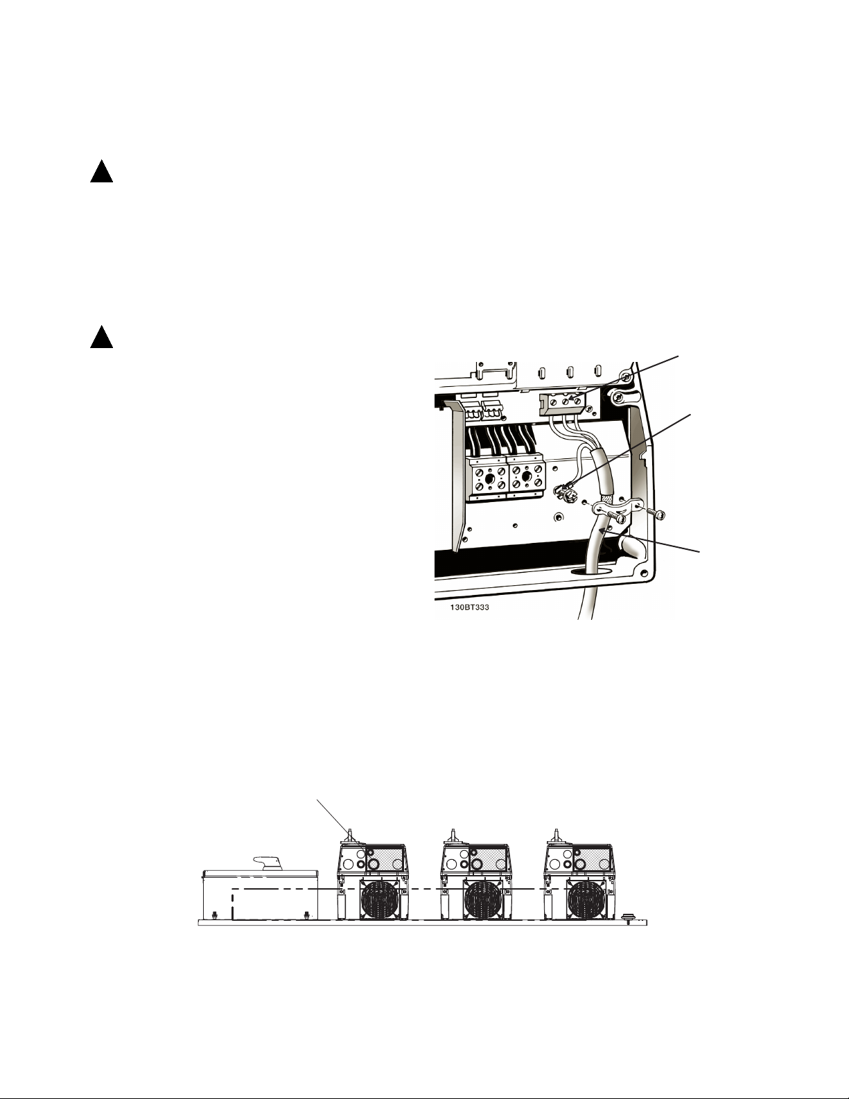
Page 6
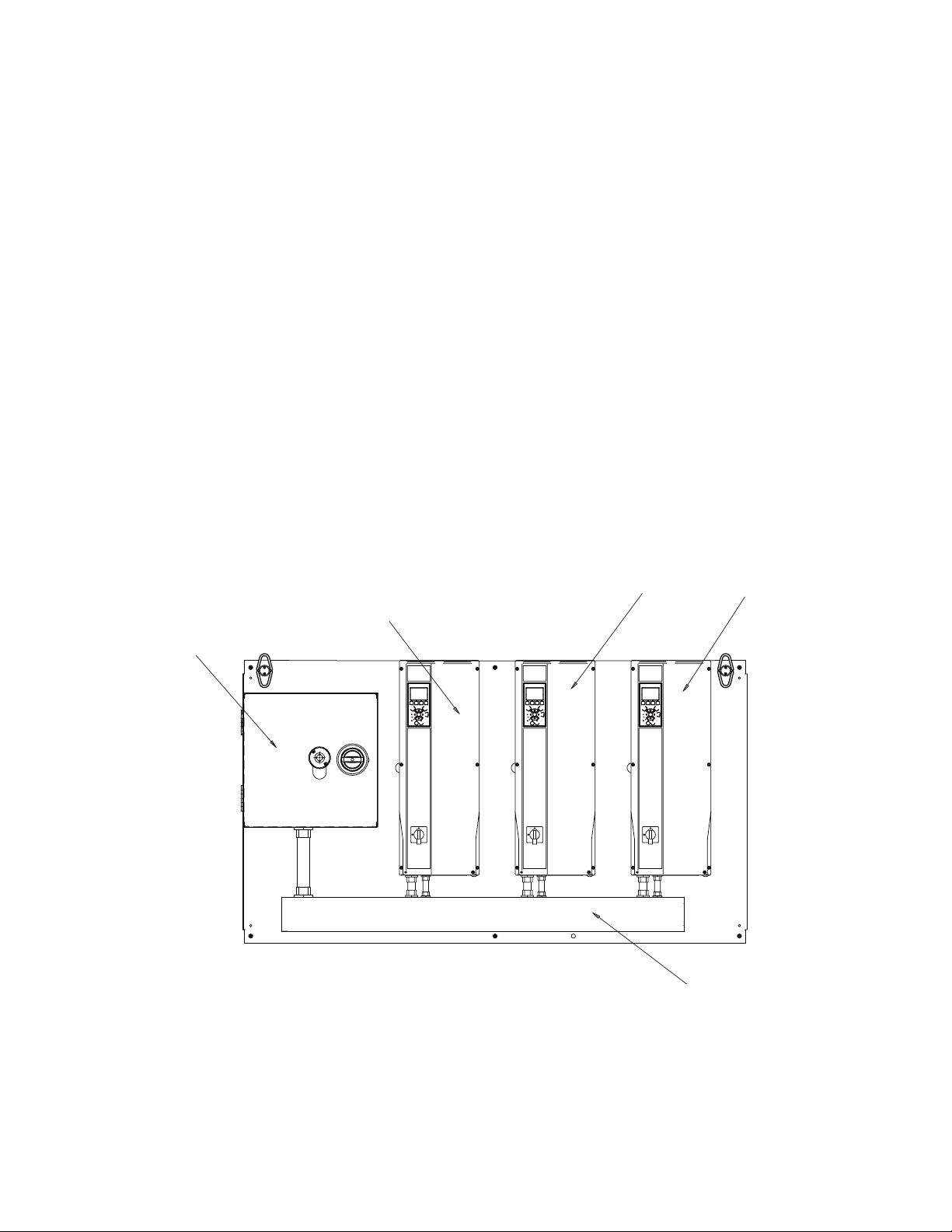
Type S-1 Controller (with or without manual by-
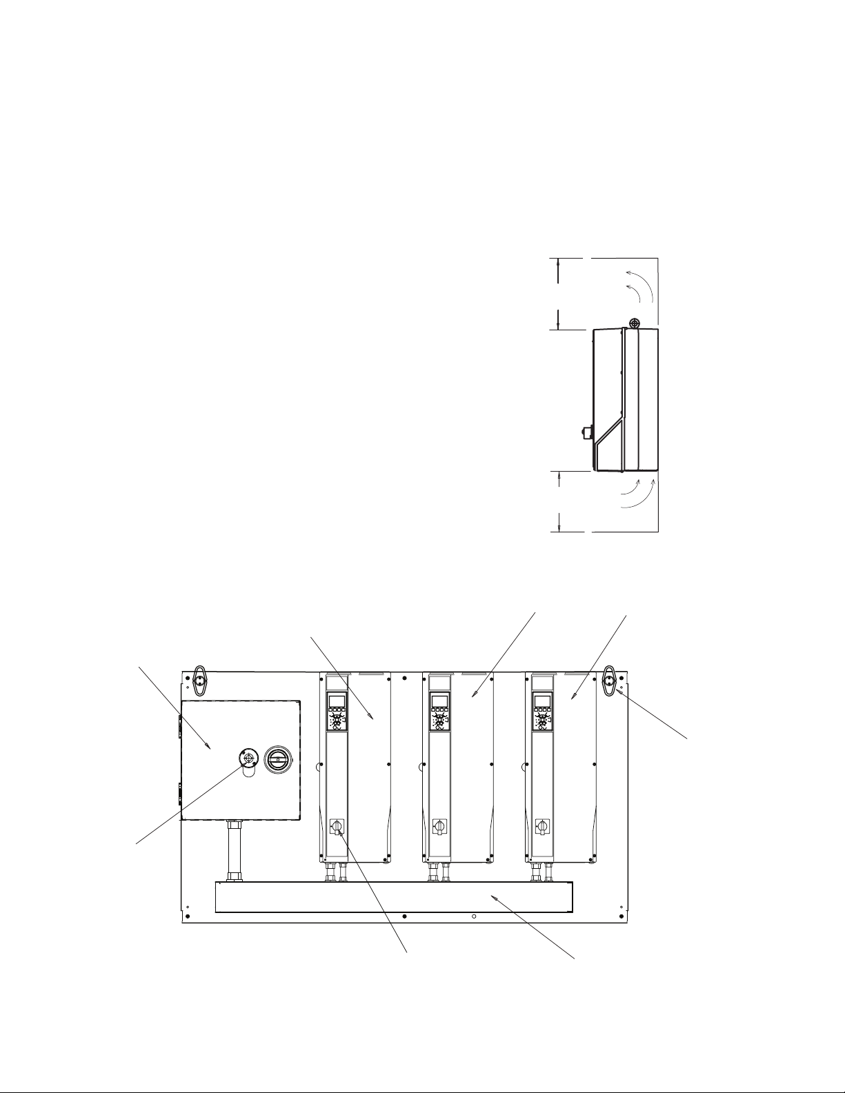
Input power panel
Master drive
Follower 1
Follower 2
Input power raceway to VFDs
pass)
The type S-1 controller comes in two different con-
gurations. One consists of a Technologic 502 master
with embedded pump controller software with up to
three follower drives. The other S-1 conguration is
the same with the addition of a manual bypass for the
master and a manual bypass for each follower drive.
The controller allows parallel operation between the
master and follower drives in response to a set point.
All drives will run at the same synchronized speed.
A-0 (1 Technologic 502 Master 0nly)
A-M (1 Technologic 502 Master only with manual
bypass)
C-0 (1 Technologic 502 Master with (1) follower – No
Staging)
C-M (1 Technologic 502 Master with (1) follower each
with manual bypass – No Staging)
D-0 (1 Technologic 502 Master with (up to 3) followers – Staging Allowed)
D-M (1 Technologic 502 Master with (up to 3) followers
each with manual bypass – Staging Allowed)
6
Figure 1-2. Master Drive with Two Followers
Page 7
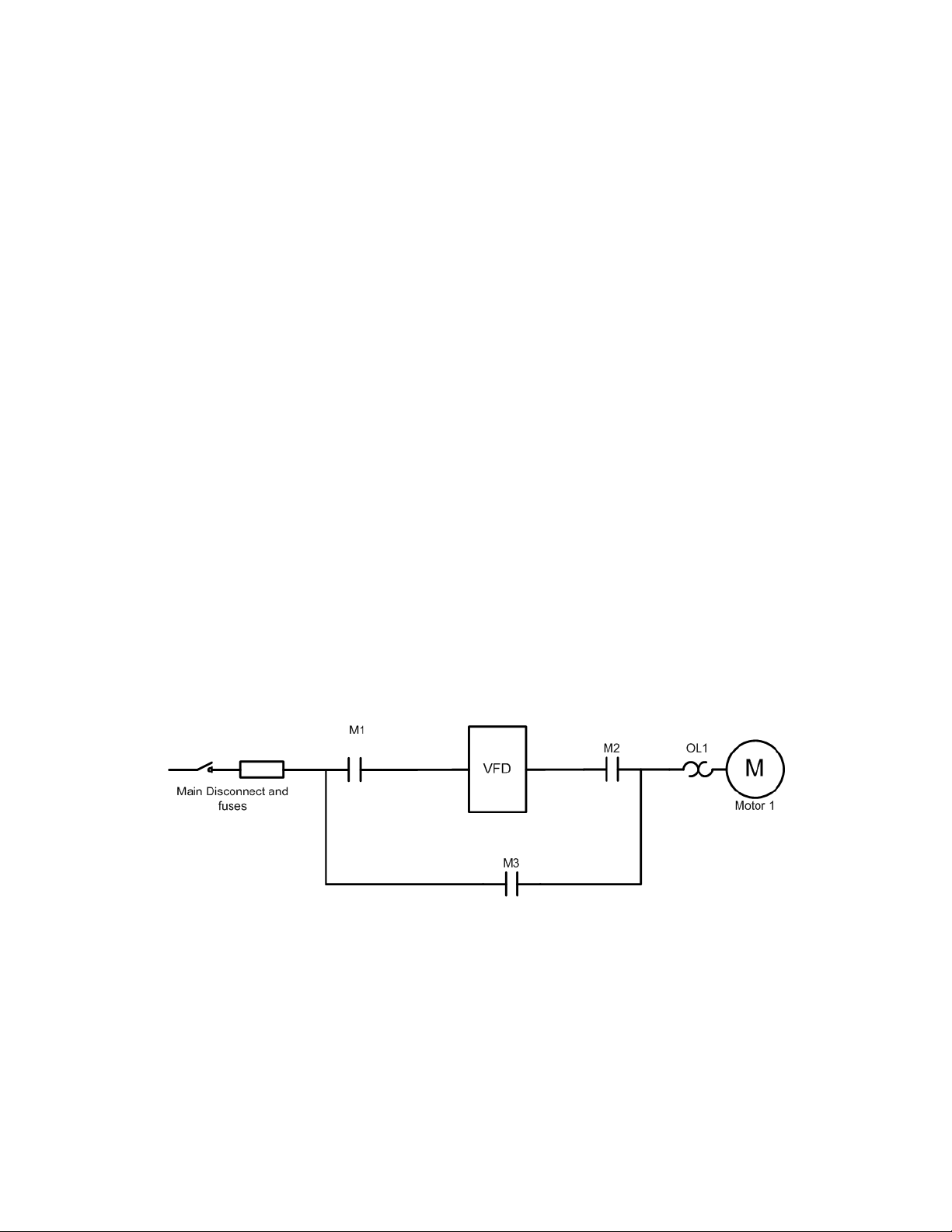
Typical Bypass Operation
Overload Protection.
With contactors M1 and M2 closed and contactor M3
open (see Figure 1-3), the pump is controlled by the
drive. Opening contactor M2 removes power to the
pump but allows the controller to remain powered.
This is the test mode and only available in the three-
contactor conguration shown. With contactors M1
and M2 open and contactor M3 closed, the pump
runs in bypass from the line input. For a two-contactor
conguration, M1 is absent. In this case, contactors
M2 and M3 control the options for running in drive or
bypass mode. The gure illustrates a drive disconnect
and fuses.
This thermally activated device provides mechanical
overload protection for the pump(s) while in bypass
operation. It measures motor current and is factory set
to the full load amps (FLA) of the pump. A 1.2 x FLA
service factor is built-in and maintained. Should the
motor current increase above that value, the overload
will calculate the level of increase to activate timing
for the trip function. The higher the current draw, the
quicker the trip response. The overload provides
Class 20 motor protection.
Figure 1-3. Basic 3-contactor Bypass Functions
7
Page 8
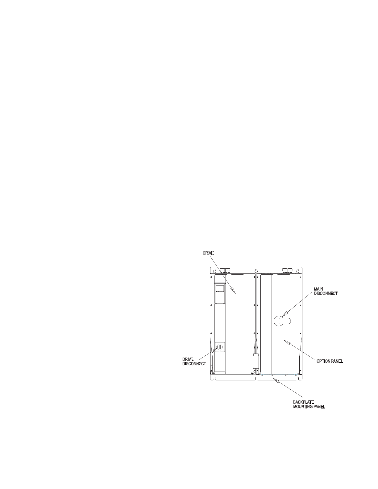
Disconnects
DRIVE
DISCONNECT
DRIVE
OPTION PANEL
BACKPLATE
MAIN
MOUNTING PANEL
DISCONNECT
Power Fusing
Main disconnect. The main disconnect removes
line input power to the controller and bypass. A main
disconnect is available in two options. For safety, the
switch must be in the OFF position before the panel
door can be opened. (See Figure 1-4.)
•
Main disconnect with built-in
fuses. Two-position (ON/OFF) ro-
tary switch, with three built-in fuses,
one on each phase.
Main disconnect with separate
•
fuses. Two-position (ON/OFF)
rotary switch with a fuse block
mounted separately from the
disconnect. Three fuses, one on
each phase, are located on the fuse
block.
Drive disconnect. Two-position (ON/OFF) rotary
switch disconnects main AC line input power to the
drive only.
Motor Alternation Selector Switch
The B3 option includes contactor motor selection. It
provides motor alternation with one drive alternating
operation between two motors. The panel mounted
Motor 1/Auto/Motor 2 selector switch provides local
control of either motor along with an auto setting that
allows auto selection through the master drive.
Two types of fusing are available for the units—main
and drive fusing. For all power fuses, use the speci-
ed fuse or an equivalent replacement only. See the
fuse ratings label on the inside cover of the unit for
ratings.
Main fusing. Main fuses are located ahead of the
drive. Main fuses are designed to protect the circuitry
within the panel but are not adequate to protect the
drive. Main fuses are dual-element, time-delay type
and mount inside the bypass enclosure.
Drive fusing. Drive fuses are located ahead of the
drive and are a fast-acting type. Drive fuses are standard in two-contactor and three-contactor bypasses.
A fuse/disconnect enclosure may be used if no options other than a fuse block and disconnect switch
are required.
8
Figure 1-4. Disconnects
Page 9
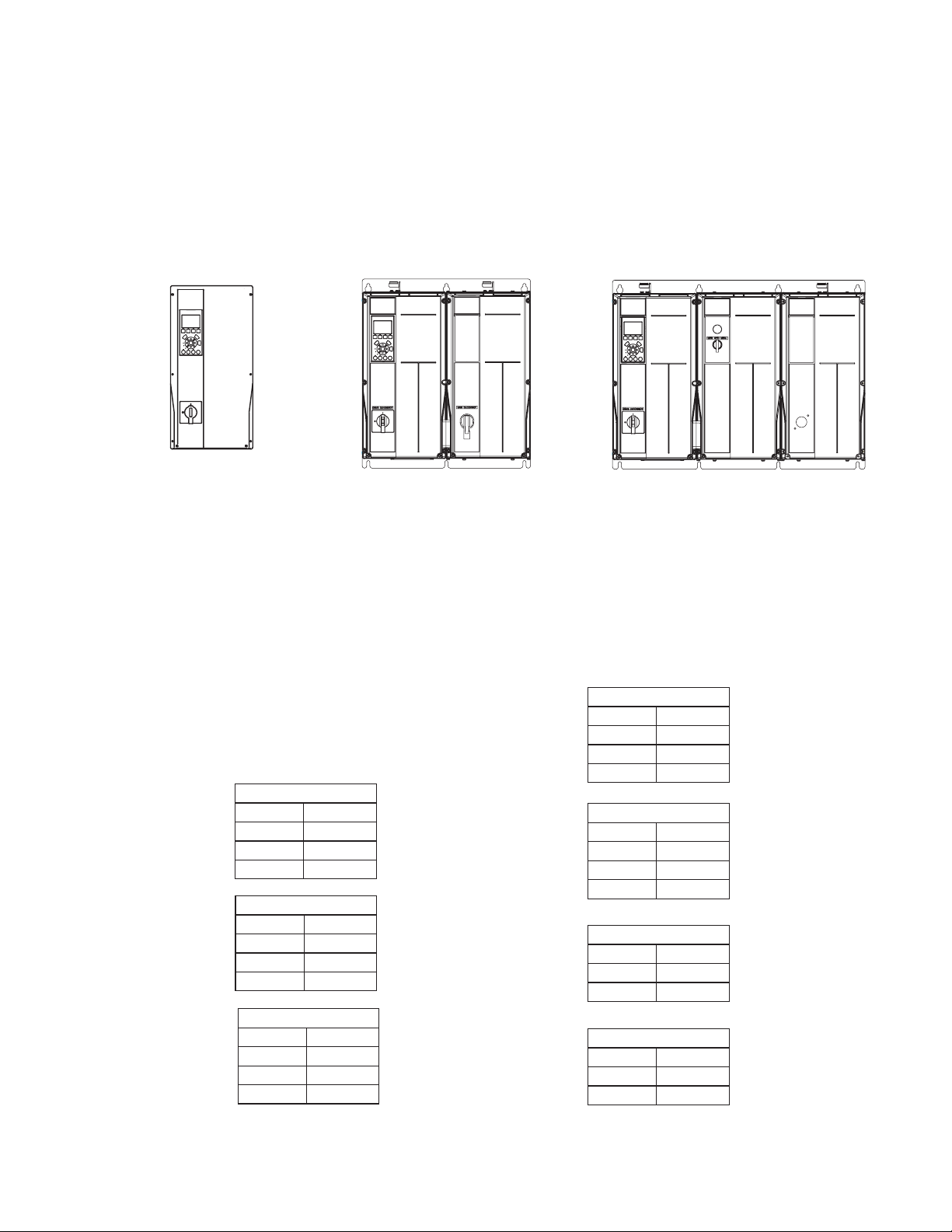
Drive Option Panel Congurations
contains the bypass as in Tier 2. Two option panels
are provided in Tier 3 with one containing the bypass
The Technologic 502 Drive Series has three tiers
of option panel enclosure types. The option panel
and the other the contactor motor selector. (See
Figure 1-5)
Tier 1 Tier 2 Tier 3
Drive with fuses
Drive with bypass Drive with bypass and contactor
and disconnect
Figure 1-5. Tier Denitions and Features
Option Panel Voltage and Frame Ratings
Table 1-1 denes the voltage and hp ratings of the
frames sizes for the drive and option panel. See the
mechanical drawing shipped with the unit for dimensions.
Frame A2 - A5
Volts VAC hp
208-230 2-5
460-480 3-10
575-600 3-10
Frame B1
Volts VAC hp
208-230 7.5-15
460-480 15-25
575-600 15-25
Frame B2
Volts VAC hp
208-230 15-20
460-480 30-40
575-600 30-40
motor selector (B3)
Frame C1
Volts VAC hp
208-230 25-30
460-480 50-75
575-600 50-75
Frame C2
Volts VAC hp
208-230 40-60
460-480 100-125
575-600 100-125
Frame D1
Volts VAC hp
460-480 150-200
575-600 150-200
Frame D2
Volts VAC hp
460-480 250-350
575-600 250-400
Table 1-1. Panel Voltage and Frame Ratings
9
Page 10

Section 2 Pre-installation
Pre-installation Check Installation Site Check
1. Compare model number to what was
ordered.
2. Ensure each of the following are rated for
same voltage:
• Power line
• Drive
• Option panel
• Motor
3. Ensure that option panel output rating is
equal to or greater than motor total full
load current for full motor performance.
• Motor power size and option panel must
match for proper overload protection.
• If panel rating is less than motor, full motor
output cannot be achieved.
4. Check motor wiring:
• Any disconnect between drive and motor
should be interlocked to drive safety
interlock circuit to avoid unwanted drive
trips.
• Because the option panel relies on the
ambient air for cooling, it is important to
observe the limitations on ambient air
temperature. Derating starts above 40°C
(104°F) and 3300 feet (1000m) elevation
above sea level.
• It is important with backpanel mounted units
to check support strength. Make sure that
the proper mounting screws or bolts are
used.
• Keep the option panel interior free from dust
and similar dirt. In construction areas, if the
unit is not powered, provide a protective
covering. It is important to ensure that the
components stay as clean as possible. It
may be necessary to clean the interior once
construction is completed.
• Keep wiring diagrams, drawings and
manuals accessible for detailed installation
and operation instructions. It is important
that the manuals be available for equipment
operators.
• Do not connect power factor correction
capacitors between drive and motor.
• Two speed motors must be wired
permanently for full speed.
• Y-start, -run motors must be wired
permanently for run.
10
Page 11

Harsh Environments
The mechanical and electrical components within
the option panel can be adversely affected due to
the environment. The effects of contaminants in the
air, either solid, liquid, or gas, are difcult to quantify
and control. Depending upon the severity of the
environment, optional NEMA 12, NEMA 3R or NEMA
4 enclosures may be used.
Airborne Liquids
Liquids in the air can condense in components. Water
vapor carried in the air is easily measured as relative
humidity, but other vapors are often more difcult
to measure or control. Steam, oil, and salt water
vapor (near sea locations) may cause corrosion of
components. In such environments, use NEMA 12
enclosures to limit the exchange of outside air into
the option enclosure. Extremely harsh environments
may require a higher level of protection.
Airborne Solids
Particles in the air may cause mechanical, electrical
or thermal failure in components. A NEMA 1 enclosure
provides a reasonable degree of protection against
falling particles, but it will not prevent the fan from
pulling dirty air into the enclosure. A typical indicator
of excessive levels of airborne particles is dust
around the fan. In dusty environments, use NEMA
12 enclosures.
Corrosive Chemicals
In environments with high temperatures and humidity,
corrosive gases such as sulfur, nitrogen and chlorine
compounds cause corrosion to occur in components.
Indications of corrosion are blackened copper or rust
on steel or oxidized aluminum. In such environments,
it is recommended that the equipment be mounted in
a cabinet with fresh air ventilation and that corrosive
compounds be kept away. A non-ventilated cabinet
tted with an air conditioner as a heat exchanger may
be used. Conformal coated circuit boards may be
specied to reduce the corrosive effects of a harsh
environment.
11
Page 12
Section 3 Installation
WARNING
!
TOOLS
Spreader bar capable of lifting up to 1000 lbs.
Max diameter 0.875 in.
Forklift, crane, hoist or other lifting device
capable of handling up to 1000 lbs. (Qualified
device operator available for operating the
equipment.)
Metric socket set: 7 - 19mm
Socket extensions: 4 & 6 in
Torx driver set: T10 - T40
Torque wrench: 6 - 170 in-lbs
Common Backpanel Mounted Units
Branch Circuit Protection
br a n c H ci r c u i t pr o t E c t i o n rE q u i r E d !
pr o v i d E b r a n c H c i r c u i t pr o t E c t i o n i n a c c o r d a n c E w i t H
t H E na t i o n a l E l E c t r i c a l co d E . fa i l u r E t o p r o v i d E b r a n c H
c i r c u i t pr o t E c t i o n in a c c o r d a n c E w i t H t H E nEc m a y
r E s u l t i n E q u i p m E n t o r p r o p E r t y d a m a g E .
Drive Fuses
If specied as an option, drive input fuses will be
factory installed in the enclosure. If not factory supplied, they must be provided by the installer as part
of installation.
Internal Option Panel Fuses
Use the specied fuse or an equivalent replacement
only for internal option panel fuses. Fuse options
include the drive disconnect and contactor fuses.
Tools and Equipment Required
In addition to the standard tool kit, the tools and devices in Table 3-1 are recommended for installation
of the unit.
Table 3-1. Tools and Equipment Required
Figure 3-1. Drive Input Fuses
Table 3-2. Connection Tightening Torques
Power (hp) Torque (in-lbs)
Frame 200-240 V 380-480 V 525-600 V Line Motor DC Brake Ground Relay
A2 2 - 5 3 - 5 3 - 5 17 17 17 28 5
A3 5 10 5 - 10 17 17 17 28 5
A5 1.5 - 5 1.5 - 10 1.5 - 10 17 17 17 28 5
B1 7.5 - 15 15 - 25 -- 17 17 13 28 5
B2 20 30 - 40 -- 22, 40 22, 40 32 29 5
12
C1 25 - 40 50 - 75 -- 88 88 88 28 5
C2 50 - 60 100 - 125 -- 124, 212 124, 212 124 29 5
D1 -- 150-200 150-200 168 168 84 29 7
D2 -- 250-350 250-400 168 168 84 29 7
Page 13
Mechanical Installation
4.0 in min.
CEILING
FLOOR
AIRFLOW
4.0 in min.
AIRFLOW
Input power panel
Master drive
Follower 1
Follower 2
Input power raceway to VFDs
Drive disconnect
Mains (line)
disconnect
Hoist ring
Lift unit by
hoist ring only
Lifting
Check the weight of unit to determine the safety of the
lifting method. (See the mechanical drawing supplied
with the equipment for unit weight.) Ensure that the
lifting device is suitable for the task. If necessary, plan
for a hoist, crane or forklift with appropriate rating to
move the units. For lifting, use hoist rings provided.
Cooling
• Mount the controller and panel vertically.
• Option panels rely on the ambient air
for cooling. It is important to observe the
limitations on ambient air temperature.
Derating start above 104oF (40oC) and 3300
feet elevation above sea level.
• Top and bottom clearance is required for
cooling (Figure 3-2). Generally, 4 to 10
inches (100 to 250 mm) minimum clearance
is required, depending upon the hp of the
unit. See the mechanical drawing shipped
with the unit for specic requirements.
Figure 3-2. Cooling Airow
Figure 3-3. Typical Unit Components
13
Page 14
WARNING
!
WARNING
!
Electrical Installation
EquipmEnt Hazard!
rotating sHafts and ElEctrical EquipmEnt can bE
Hazardous. it is strongly rEcommEndEd tHat all
E l E c t r i c a l w o r k c o n f o r m t o a l l n a t i o n a l a n d l o c a l
r E g u l a t i o n s . in s t a l l a t i o n , s t a r t -u p , a n d m a i n t E n a n c E
s H o u l d b E p E r f o r m E d o n l y b y q u a l i f i E d p E r s o n n E l . fa i l u r E
t o f o l l o w l o c a l r E g u l a t i o n s c o u l d r E s u l t i n d E a t H o r
s E r i o u s i n j u r y .
• Motor control equipment and electronic
controls are connected to hazardous line
voltages. Extreme care should be taken to
protect against electrical hazard.
• Proper protective grounding of the
equipment must be established. Ground
currents are higher than 3 mA.
• A dedicated ground wire is required.
• Wear safety glasses whenever working on
electric control or rotating equipment.
notE
ma k E a l l p o w E r c o n n E c t i o n s w i t H m i n i m u m 75o c r a t E d
c o p p E r w i r i n g f o r i n s t a l l a t i o n s i n no r t H am E r i c a .
in d u c E d vo l t a g E !
ru n o u t p u t m o t o r c a b l E s f r o m m u l t i p l E d r i v E s s E p a r a t E l y .
in d u c E d v o l t a g E f r o m o u t p u t m o t o r c a b l E s r u n t o g E t H E r
c a n c H a r g E E q u i p m E n t c a p a c i t o r s E v E n w i t H t H E E q u i p m E n t
t u r n E d o f f a n d l o c k E d o u t . fa i l u r E t o r u n o u t p u t c a b l E s
s E p a r a t E l y c o u l d r E s u l t i n d E a t H o r s E r i o u s i n j u r y .
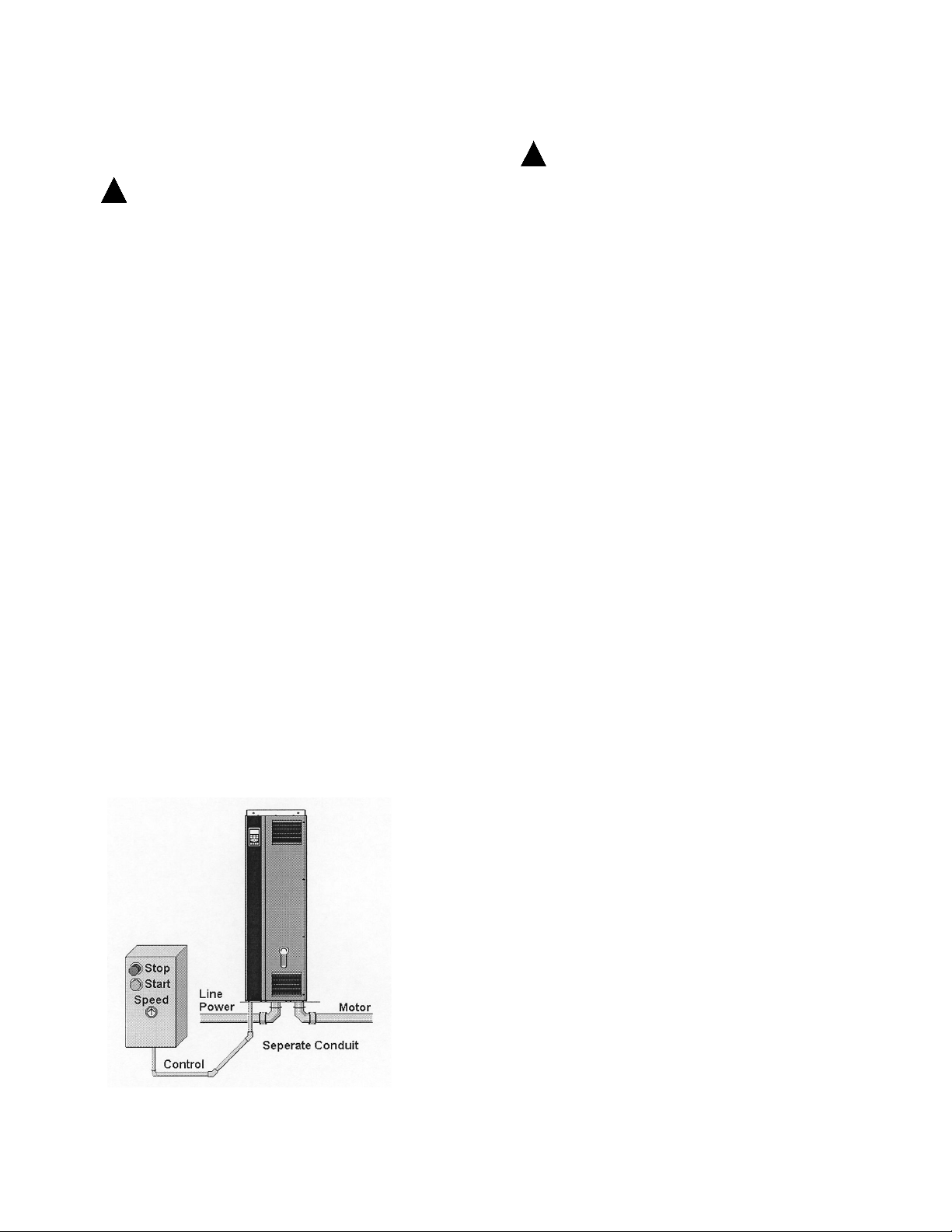
notE
ru n d r i v E i n p u t p o w E r , m o t o r w i r i n g , a n d c o n t r o l
w i r i n g i n t H r E E s E p a r a t E m E t a l l i c c o n d u i t s o r r a c E w a y s
f o r H i g H f r E q u E n c y n o i s E i s o l a t i o n . fa i l u r E t o i s o l a t E
p o w E r , m o t o r , a n d c o n t r o l w i r i n g c o u l d r E s u l t i n l E s s
t H a n o p t i m u m c o n t r o l l E r a n d a s s o c i a t E d E q u i p m E n t
p E r f o r m a n c E .
• Because the wiring from the option
enclosure to the motor carries high
frequency electrical pulses, it is important
that no other wires are run in this conduit. If
the incoming power wiring is run in the same
conduit as the motor wiring, these pulses
can couple electrical noise back onto the
building power grid.
At least three separate conduits must be connected
to the panel option. (See Figure 3-4.)
• Power wiring into the enclosure (and ground
back to the distribution panel)
14
• Power wiring from the enclosure to the
motor (and earth ground)
• Control wiring
Control wiring should always be isolated from the
high voltage power wiring.
Avoid getting metal chips into electronics.
Follow the connection procedures as illustrated in
the drawing provided with the unit.
For internal component identication, see Figure
3-5.
Figure 3-4. Power Connections
Page 15
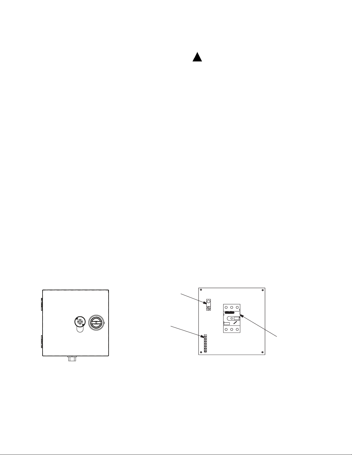
OT 45...100 M3
Ground lug
Line (mains)
disconnect
Ground bar
L1 L2
L3
Wire Type Rating
WARNING
!
• Use wiring corresponding to the wire
rating specication provided.
• The wire rating specication is located
on the wire rating label inside the cover
of the option panel.
Terminal Tightening Torques
• Tighten all connections to the torque
specication provided in Table 3-2.
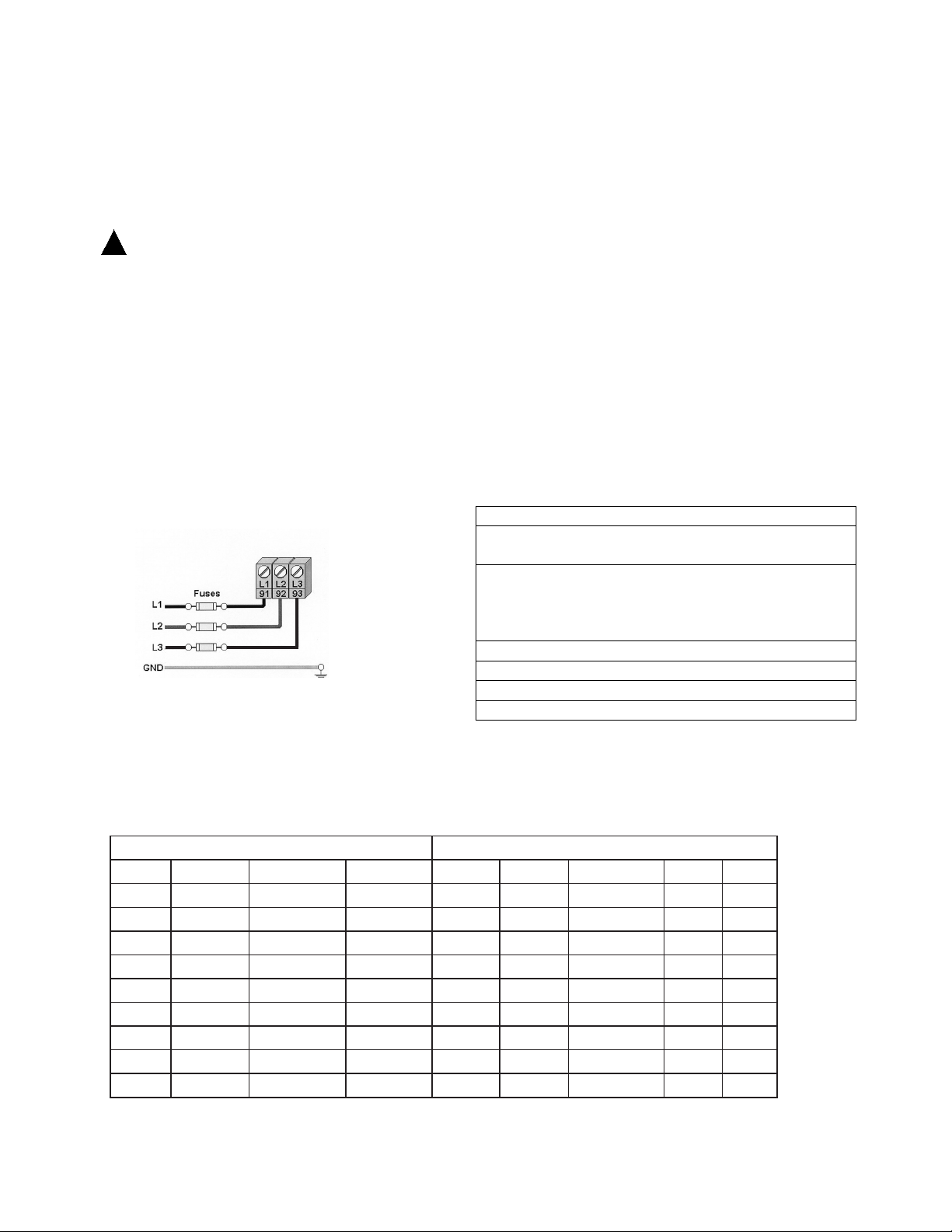
Line Input (Mains) Connection
• Size wiring based upon the input current
of the drive. Recommended wire sizes are
provided on the connection drawing of the
unit.
• Local codes must be complied with for cable
sizes.
ru n i n p u t p o w E r , m o t o r w i r i n g a n d c o n t r o l w i r i n g in
t H r E E s E p a r a t E m E t a l l i c c o n d u i t s o r r a c E w a y s f o r H i g H
f r E q u E n c y n o i s E i s o l a t i o n . fa i l u r E t o i s o l a t E p o w E r ,
m o t o r a n d c o n t r o l w i r i n g c o u l d r E s u l t i n l E s s t H a n
o p t i m u m d r i v E a n d a s s o c i a t E d E q u i p m E n t p E r f o r m a n c E .
• Connect 3-phase AC input power wire
to terminals L1, L2, and L3 on the main
disconnect located in the input power panel
(see Figure 3-3).
• Depending on the conguration of the
equipment, input power may be connected
to a circuit breaker or input disconnect.
• Use with Isolated Input Source. Many
utility power systems are referenced to earth
ground. Although not as common, the input
power may be an isolated source. All drives
may be used with an isolated input source
as well as with ground reference power
lines.
notE
sE E f i g u r E s 3-12 a n d 3-13 f o r p o w E r , m o t o r a n d c o n t r o l
w i r i n g d i a g r a m s .
Exterior
Interior
Figure 3-5. Input Power Panel with Line Disconnect
15
Page 16
Motor Wiring
WARNING
!
WARNING
!
NOTE: CONNECT MOTOR LEADS
DIRECTLY TO VFD THROUGH ACCESS
PANEL. DO NOT ROUTE THROUGH
RACEWAY.
notE
sE E fi g u r E s 3-12 a n d 3-13 f o r p o w E r , m o t o r a n d
c o n t r o l w i r i n g d i a g r a m s .
in d u c E d vo l t a g E !
ru n o u t p u t m o t o r c a b l E s f r o m m u l t i p l E d r i v E s s E p a r a t E l y .
in d u c E d v o l t a g E f r o m o u t p u t m o t o r c a b l E s r u n t o g E t H E r
c a n c H a r g E E q u i p m E n t c a p a c i t o r s E v E n w i t H t H E E q u i p m E n t
t u r n E d o f f a n d l o c k E d o u t . fa i l u r E t o r u n o u t p u t m o t o r
c a b l E s s E p a r a t E l y c o u l d r E s u l t i n d E a t H o r s E r i o u s
i n j u r y .
wi r i n g is o l a t i o n !
ru n i n p u t p o w E r , m o t o r w i r i n g a n d c o n t r o l w i r i n g in
t H r E E s E p a r a t E m E t a l l i c c o n d u i t s o r r a c E w a y s f o r H i g H
f r E q u E n c y n o i s E i s o l a t i o n . fa i l u r E t o i s o l a t E p o w E r ,
m o t o r a n d c o n t r o l w i r i n g c o u l d r E s u l t i n l E s s t H a n
o p t i m u m d r i v E a n d a s s o c i a t E d E q u i p m E n t p E r f o r m a n c E .
• Motor wiring access panels are provided at
the base of the units as shown in Figure 3-6:
• Torque terminals in accordance with the
information provided in Table 3-2.
• Motor wiring should never exceed the
following maximum distances:
1000 ft (300m) for unshielded
500 ft (150m) for shielded
• Motor wiring should always be as short as
practical.
Motor terminals
T1, T2, T3
Ground
• Connect the 3-phase motor wiring to bypass
terminals T1 (U), T2 (V), and T3 (W). See
the connection drawing provided with unit.
• Depending on the conguration of the
equipment, motor wiring may be connected
to an electrical or mechanical overload, a
contactor, or terminal block (see Figure 3-7).
Figure 3-6. Wiring Access Panels (bottom view)
Motor wiring
Figure 3-7. Sample Motor Wiring
16
Page 17

Grounding (Earthing)
WARNING
!
gr o u n d i n g Ha z a r d !
fo r o p E r a t o r s a f E t y , i t i s i m p o r t a n t t o g r o u n d d r i v E a n d
o p t i o n p a n E l p r o p E r l y . fa i l u r E t o g r o u n d d r i v E a n d o p t i o n
p a n E l p r o p E r l y c o u l d r E s u l t i n d E a t H o r s E r i o u s i n j u r y .
no t E
it i s t H E r E s p o n s i b i l i t y o f t H E u s E r o r c E r t i f i E d E l E c t r i c a l
i n s t a l l E r t o E n s u r E c o r r E c t g r o u n d i n g (E a r t H i n g ) o f
t H E E q u i p m E n t in a c c o r d a n c E w i t H n a t i o n a l a n d l o c a l
E l E c t r i c a l c o d E s a n d s t a n d a r d s .
• Follow all local and national codes for proper
electrical equipment grounding (earthing).
• Proper protective grounding of the
equipment must be established. Ground
currents are higher than 3 mA.
• A dedicated ground wire is required.
• Do not use conduit connected to the option
panel as a replacement for a ground wire.
• Do not ground one panel to another in a
“daisy chain” fashion. Each panel must have
a dedicated ground connection.
• A high strand count ground wire is preferred
for dissipating high frequency electrical
noise.
• Keep the ground wire connections as short
as possible.
notE
sE E f i g u r E s 3-12 a n d 3-13 f o r p o w E r , m o t o r a n d c o n t r o l
w i r i n g d i a g r a m s .
• Connect the ground wire directly to a reliable
earth ground. Grounding studs are provided
on the back plate of the option panel for
grounding.
17
Page 18
Control Wiring
WARNING
!
ru n i n p u t p o w E r , m o t o r w i r i n g a n d c o n t r o l w i r i n g i n
t H r E E s E p a r a t E m E t a l l i c c o n d u i t s o r r a c E w a y s f o r H i g H
f r E q u E n c y n o i s E i s o l a t i o n . fa i l u r E t o i s o l a t E p o w E r ,
m o t o r a n d c o n t r o l w i r i n g c o u l d r E s u l t i n l E s s t H a n
o p t i m u m d r i v E a n d a s s o c i a t E d E q u i p m E n t p E r f o r m a n c E .
• It is recommended that control wiring is
rated for 600 volts for 480 V and 600 V
drives and 300 volts for 200-240 V drives.
Drive Control Terminals
Denitions of the drive terminals are summarized in
Table 3-3. Figure 3-9 shows the removable controller
connectors and terminals.
• Connector 1 provides four programmable
digital inputs, two additional digital terminals
programmable as input or output, a 24 VDC
terminal supply voltage, and a common for
optional customer supplied 24 VDC voltage.
• Isolate control wiring from high power
components in the drive.
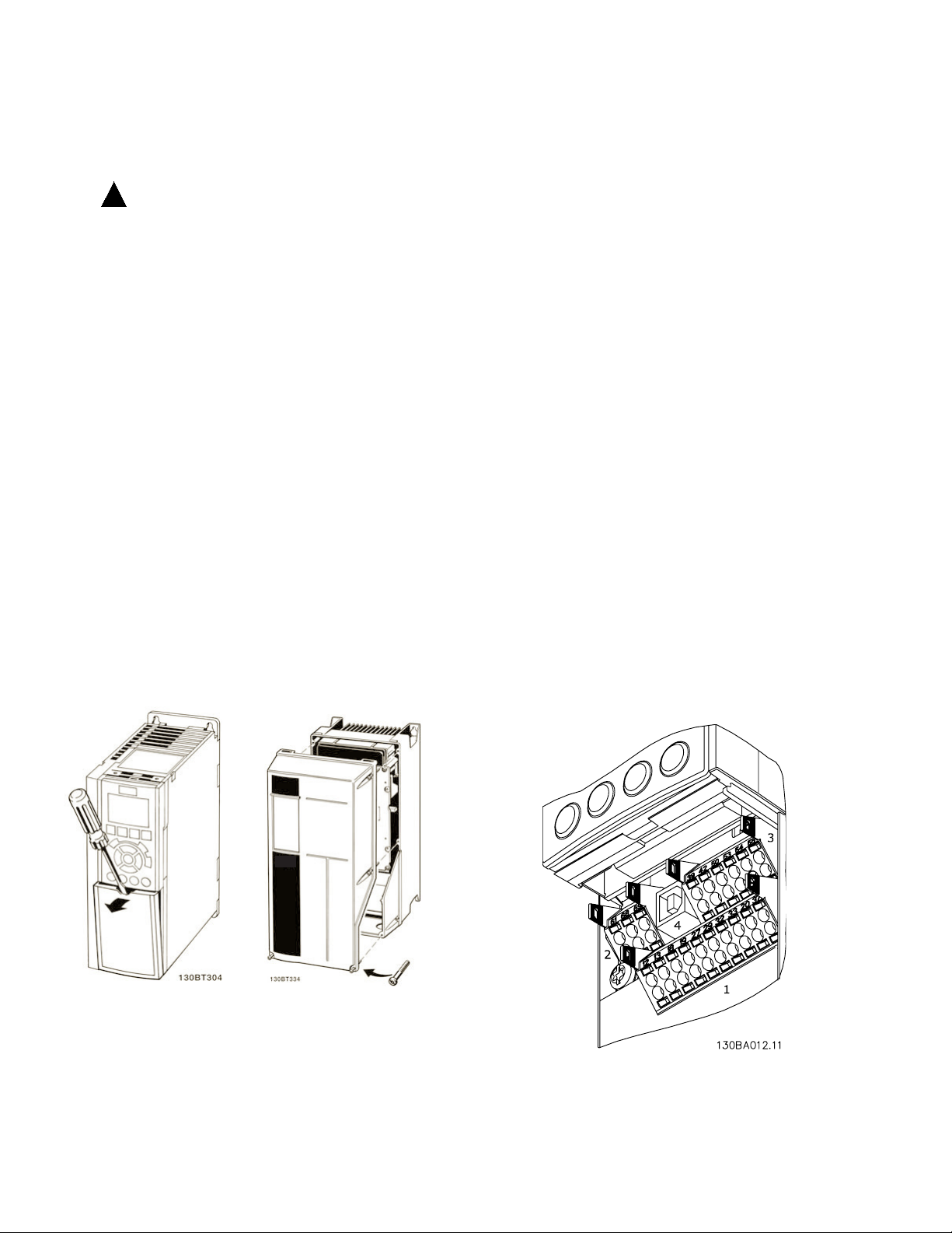
Control Wiring Access
• For units 5 hp or less (208 V) and 10 hp or
less (480 V), remove access cover plate with
screw driver. (See Figure 3-8.)
• For larger size units, remove front cover of
unit to access internally mounted control
terminals. (See Figure 3-8.)
• Connector 2 is for the serial
communications EIA-485 connector with
terminal 68 (+) and 69 (-).
• Connector 3 provides two analog inputs,
one analog output, 10 VDC supply voltage,
and commons for the inputs and output.
• Connector 4 is a USB port available for
use with the MCT-10 drive programming
software.
• Also provided are two Form C relay outputs
that are in various locations depending upon
the controller conguration and size.
Figure 3-8. Control Terminals Access
18
Figure 3-9. Drive Control Terminals
Page 19
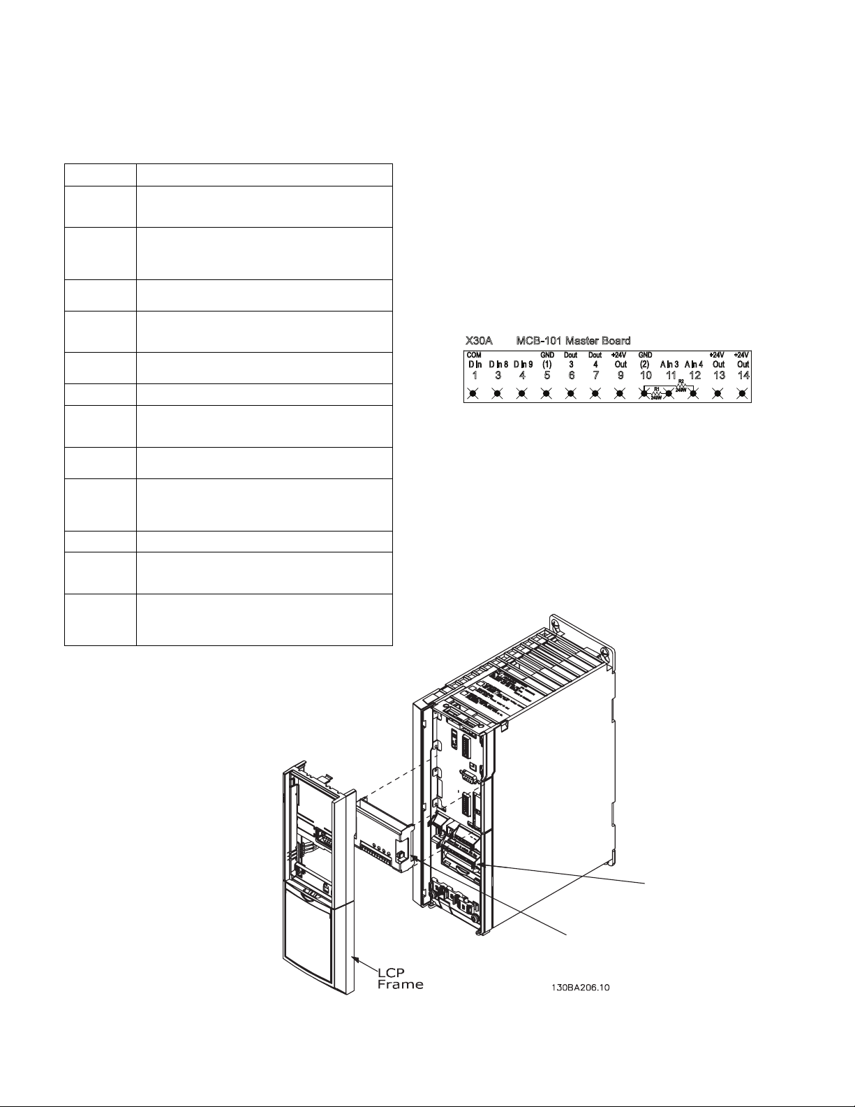
Table 3-3. Drive Control Terminals Functions
Terminal No.
Function
01, 02, 03
04, 05, 06
Form-C relay output. Useable for AC or DC voltage and
resistive or inductive loads. See drive support materials for
details on voltage and current ratings and relay location.
12, 13
24 VDC digital sup ply voltage. Useable f or digital inputs and
external transducers. T o use the 24 VDC for digital input
common, program param eter 5-00 for PNP operation.
Maximum output current is 200 mA total for all 24V loads.
18, 19, 32, 33
Digital inputs. Selectable for NPN or PNP function in
parameter 5-00. Default is PNP.
27, 29
Digital inputs or outputs. Programmable for either. Parameter
5-01 for terminal 27 and 5- 02 for 29 selects input/output
function. Default setting is input.
20
Common for digital inputs. To use for digital input common,
program parameter 5-00 for NPN operation.
39
Common for analog output.
42
Analog output. Programm able for various functions in
parameter 6-5x. The analog signal is 0 to 20 mA or 4 to 20 mA
at a maximum of 500 Ω.
50
10 VDC analog supply voltage. 15 mA maximum commonly
used for a potentiometer or thermistor.
53, 54
Analog input. Selectable for voltage (0-10 V) or current (0- or
4-20 mA). Closed is for current and open is for voltage.
Switches are located on the drive control card behind the
removable LCP. See drive support materials for details.
55
Common for analog inputs.
61
Common for serial communication. Do not use to terminate
shields. See drive support materials for proper shield
termination.
68 (+), 69 (-)
RS-485 interface. When the drive is connected to an RS-485
serial communication bus, a drive control card switch is
provided for termination resistance. ON for term ination and
OFF for no termination. See drive support materials for details.
MCB101
master board
Drive terminals
R1
249W
3 4 765 9 101
MCB-101 Master Board
11 12
X30A
13 14
D in
COM
D in 8 D in 9
(1)
GND3Dout4Dout
Out
+24V
(2)
GND
A in 3 A in 4 Out
+24V
Out
+24V
R2
249W
MCB-101 Master Control Board
The Master drive only contains the MCD-101 Master
Board which features additional programmable
connection terminals (see Figure 3-10). Typically,
differential pressure switches, remote system run and
system status, and an optional low suction pressure
switch are connected to these terminals. (See Figure
3-12, Control Wiring Schematic Diagram.)
Figure 3-10. Master Board Control Terminals
notE
sE E f i g u r E s 3-12 a n d 3-13 f o r p o w E r , m o t o r a n d c o n t r o l
w i r i n g d i a g r a m s .
notE
sE E f i g u r E s 3-12 a n d 3-13 f o r p o w E r , m o t o r a n d c o n t r o l
w i r i n g d i a g r a m s .
Figure 3-11. Master Board Terminals Location
19
Page 20
Pressure and Feedback Wiring
Serial Communications Programming
Connect differential pressure wiring and feedback
transmitter wiring to terminals as shown in Figure
3-9.
Control Terminal Programming
Control terminals must be programmed. Terminals
are multi-functional. Each terminal has a parameter
associated with it for setting the desired function. It is
essential for operation of the equipment that the control terminals are programmed correctly. Installation
programming for units is factory set. See programming in this manual for more details.
See Figure 3-13 for the control terminals schematic
diagram.
Serial Communication Bus Connection
The bypass reports serial communication data to host
systems through the drive. Connection to the serial
communication network is made either through the
EIA-485 terminals on the controller (Figure 3-9) or, for
other protocols, terminals located on the communication option card. For option card connection, see the
option card instructions provided with the unit.
• For bypass serial communication protocols
using the EIA-485 terminals, make connections
in the following manner.
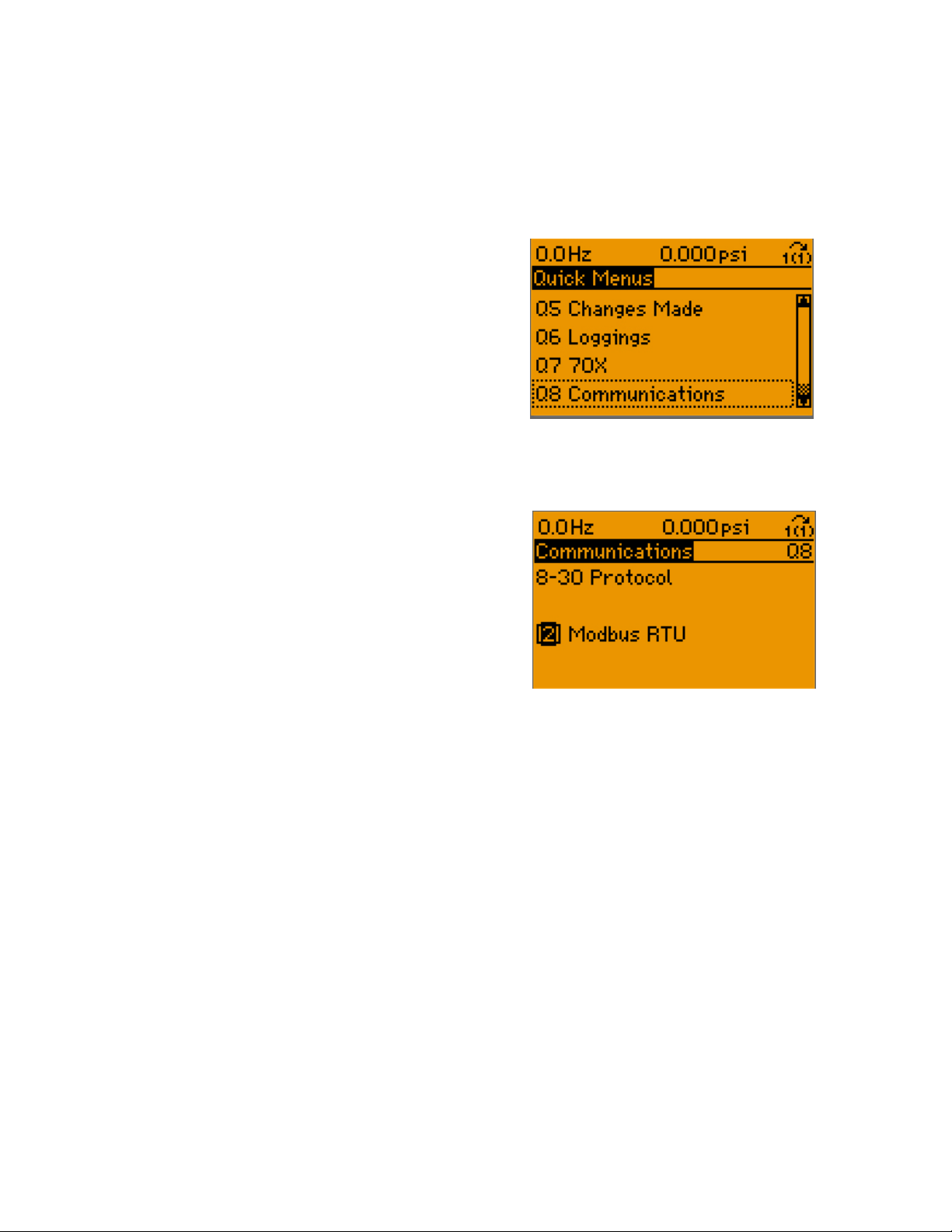
Select the serial communication protocol type in Quick
Menu item Q8, Communications.
Press the OK key to access the parameter choices
and scroll to parameter 8-30, Protocol to select the
protocol in use.
notE
dE t a i l E d s E r i a l c o m m u n i c a t i o n i n s t r u c t i o n s a r E s H o w n in
t H E a p p E n d i x a t t H E E n d o f t H i s m a n u a l .
notE
it i s r E c o m m E n d E d t o u s E b r a i d E d -s H i E l d E d , t w i s t E d -p a i r
c a b l E s t o r E d u c E n o i s E b E t w E E n c o n d u c t o r s .
1. Connect signal wires to terminal (+) 68 and
terminal (-) 69 on control terminals of controller.
2. Terminate shield to grounded restraining clip
provided by stripping wire insulation at point of
contact.
3. If shielded cabling is used, do not connect end
of shield to terminal 61.
20
Page 21
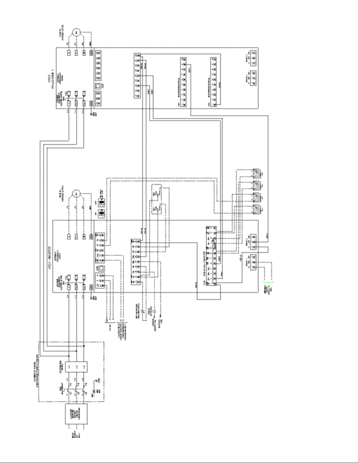
Figure 3-12. Customer Wiring Schematic Diagram, VFD with 1 Follower
21
Page 22
M1
1T1
1T2
1T3
PUMP
MOTOR #1
60 Hz
3Ø
POWER
INPUT
L13
L11
L12
DISCONNECT
L1
L2
L3
GND
BAR
GND
(T1)
(T2)
(T3)
(L1)
(L2)
(L3)
WL3
GND
VL2
L1 U
MASTER
L13
L11
L12
MAIN
GND
GND
BLOCK
DISTRIBUTION
L13
L11
L12
GND
BAR
GND
CUSTOMER
SUPPLIED
BRANCH
CIRCUIT
PROTECTION
208V-600V
POWER TO
SLAVE VFD'S
4 5 6
RELAY 2
1 2 3
RELAY 1
C NO NCC NO NC
VARIABLE
FREQUENCY
DRIVE
RS485
DP3 DP4DP2DP1
VFD4-18
2J27
GENERAL
ALARM
240VAC, 2A
MAX.
(+)
(-)
CUSTOM FIELD
CONNECTION FOR
CONFIGURABLE
ANALOG OUTPUT
P
COM
N
DISCONNECT ENCLOSURE
COMMON PANEL
USB
TO VFD4-27
2J28
VFD2-27
2K08
TO VFD3-27
2J18
VFD4-27
2K28
VFD2-18
2K07
VFD3-18
2K17
VFD1-20
VFD1-5
1R21
VFD1-4
VFD1
20333219 27 29181312
2 3 4 76 9101
MCB-101 AUX. CONNECTOR
11 12
X30A
13
Din
COM
Din 7 Din 8 Din 9 3
Dout
4
Dout
Out
+24V
(2)
GND
Ain 3 Ain 4 Out
+24V
Out
+24V
Din Din
D I/O D I/O
Din Din Din
COM
Out
+24V
61 68 69 504239 53 54 55
COM P N A Out
COM
A Out Out
+10V
Ain Ain Ain
COM
OPT. LOW SUCTION
PRESSURE SWITCH
SYSTEM RUN
REMOTE
CUSTOMER
SUPPLIED (+24V)
RUN STATUS
(+24V)
1 2
ON
1 2
ON
ON=0-20mA
OFF=0-10V
S201 S202
DS1
FU1
(LOCATED ON VFD)
DISCONNECT
V/S PUMP
R1
249W
R2
249W
2K08
VFD2-33
2L08
VFD2-20
1K18
VFD1-12
2B02 2C02 2C02
14
Out
+24V
VFD3-27
2K18
FEEDBACK Ain1
4-20mA
FEEDBACK Ain2
4-20mA
FEEDBACK Ain3
4-20mA
FEEDBACK Ain4
4-20mA
(-) (+) (-) (+) (-) (+)(-) (+)
22
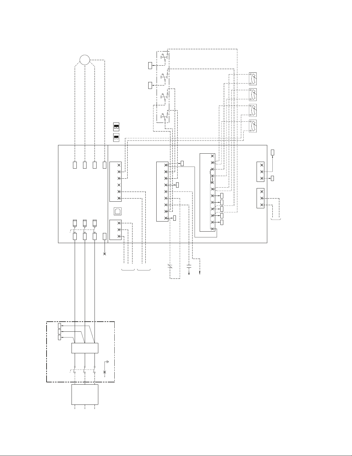
Figure 3-13.1. Customer Wiring Schematic Diagram, VFD with 2 or 3 Followers (1 of 2)
Page 23
M2
2T1
2T2
2T3
PUMP
MOTOR #2
DIST. BLK
FROM
POWER
INPUT
L13
L11
L12
W
GND
V
U
FOLLOWER 1
L13
L11
L12
GND
GND
GND
BAR
4 5 6
RELAY 2
1 2 3
RELAY 1
C NO NCC NO NC
VARIABLE
FREQUENCY
DRIVE
COMMON PANEL
LOCATED IN
ENCLOSURE
DISCONNECT
X30A-6
1N19
X30A-2
1N17
VFD1-29
1K24
VFD1-20
1L24
M4
4T1
4T2
4T3L13
L11
L12
W
GND
V
U
FOLLOWER 3 (OPT.)
GND
GND
GND
BAR
4 5 6
RELAY 2
1 2 3
RELAY 1
C NO NCC NO NC
VARIABLE
FREQUENCY
DRIVE
USB
VFD1-5
1R24
TO DP4
1I30
PUMP
MOTOR #4
M3
3T1
3T2
3T3
PUMP
MOTOR #3
W
GND
V
U
FOLLOWER 2 (OPT.)
L13
L11
L12
GND
GND
GND
BAR
4 5 6
RELAY 2
1 2 3
RELAY 1
C NO NCC NO NC
VARIABLE
FREQUENCY
DRIVE
X30A-7
1N20
TO DP3
1I29
VFD1-29
VFD1-20
VFD1-29
VFD1-20
VFD2 VFD4VFD3
61 68 69 504239 53 54 55
20
333219 27 29181312
Out
+24V
Din Din
D I/O D I/O
Din Din Din
COM
Out
+24V
COM P N A Out
COM
A Out Out
+10V
Ain Ain Ain
COM
USB
61 68 69 504239 53 54 55
20
333219 27 29181312
Out
+24V
Din Din
D I/O D I/O
Din Din Din
COM
Out
+24V
COM P N A Out
COM
A Out Out
+10V
Ain Ain Ain
COM
USB
61 68 69 504239 53 54 55
20
333219 27 29181312
Out
+24V
Din Din
D I/O D I/O
Din Din Din
COM
Out
+24V
COM P N A Out
COM
A Out Out
+10V
Ain Ain Ain
COM
L3
L2
L1
DS2
FU2
(LOCATED ON VFD)
DISCONNECT
V/S PUMP
L3
L2
L1
DS3
FU3
(LOCATED ON VFD)
DISCONNECT
V/S PUMP
L3
L2
L1
DS4
FU4
(LOCATED ON VFD)
DISCONNECT
V/S PUMP
1B09
1B09
1B10
X30A-4
1N18
X30A-3
1N18
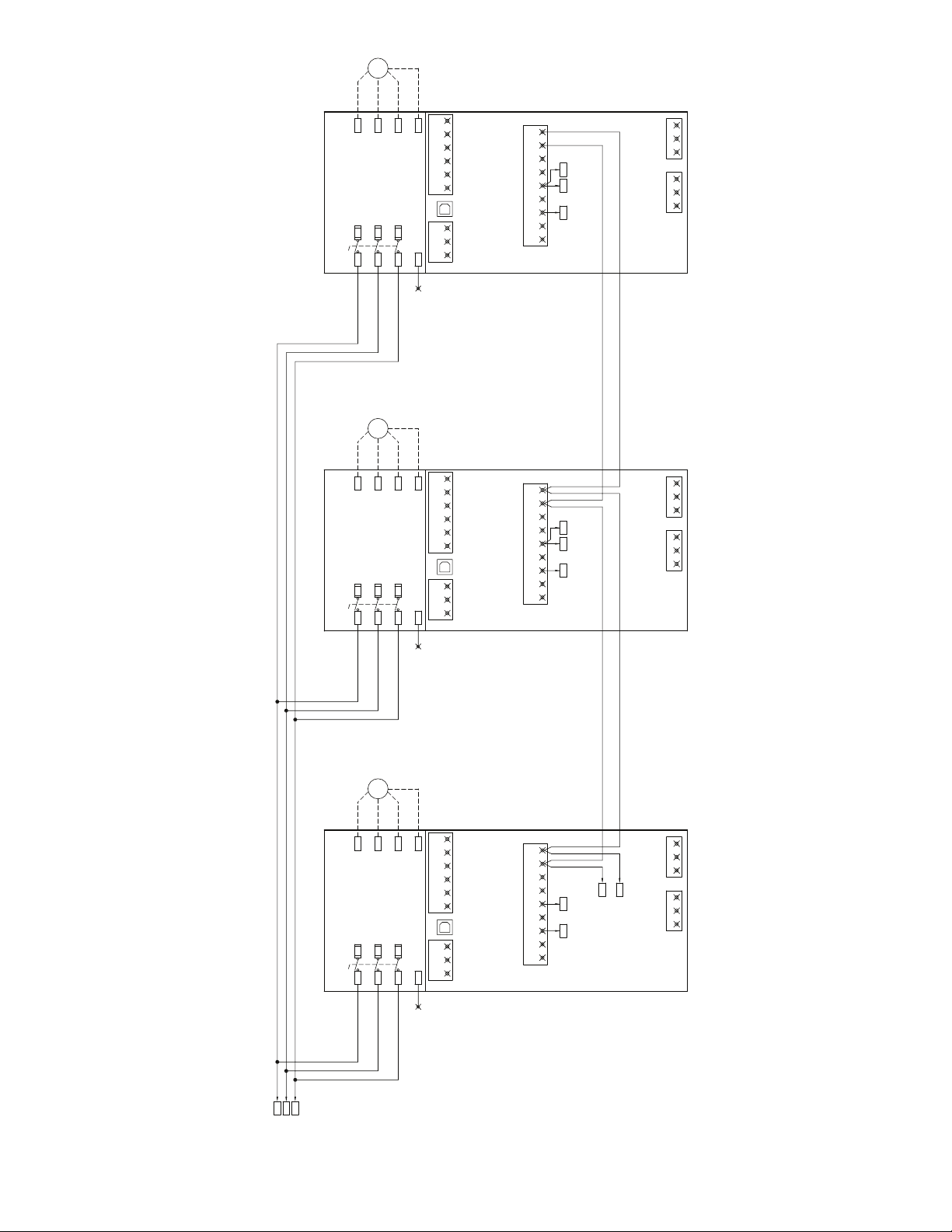
Figure 3-13.2. Customer Wiring Schematic Diagram, VFD with 2 or 3 Followers (2 of 2)
23
Page 24

Installation of Backpanel Mounted
FLOW
FLOW
FLOW
FLOW
Drives and Pumps
notE
sE E f i g u r E s 3-12 a n d 3-13 f o r p o w E r , m o t o r a n d c o n t r o l
w i r i n g d i a g r a m s .
For Installation of drives and pumps mounted on
a common backpanel (see Figure 3-14), follow the
installation procedures in Section 3 minus the motor
wiring information since this will be factory installed.
Also, the motor and system control parameters will
be factory set for the Master drive and Followers prior
to shipping.
Follow the pre-start up and start up procedures as
described in Section 4.
24
Figure 3-14. Backpanel Mounted Drives and Pumps (front and side views)
Page 25

Installation of 70X Series Drives and
Pumps
A 70X conguration consists of one variable speed
pump (lead pump) connected to the 70X controller,
and from 1 to 3 constant speed pumps connected
to mains through a contactor controlled by the 70X
controller. (See Figure 3-15.)
The 70X controller monitors system pressure and
stages on and off constant speed pumps as needed
to maintain system pressure. Parameter 27-20,
Normal Operating Range % is used to dene the
acceptable deviation from the setpoint before staging
or destaging takes place. This parameter is dened
as a % of parameter 3-03, Maximum Reference.
(See Figure 3-16 for customer connection schematic
diagram.)
Staging:
When the system demand increases the 70X
controller will increase the speed of the lead pump
until it reaches its maximum speed. If the system
demand continues to increase, it will no longer be able
to maintain the desired system pressure. Once the
pressure drops below the Normal Operating Range for
the time set in parameter 39-11, Stage Proof Timer,
the controller will stage on a constant speed pump
and ramp the lead pump to its minimum speed.
De-Staging:
When system demand decreases, the 70X controller
will decrease the speed on the lead pump until it
reaches its minimum speed. If the system demand
continues to decrease, the pressure will exceed the
Normal Operating Range. If this continues for the time
set in parameter 39-14, De-Stage Proof Timer, the
controller will destage a constant speed pump and
ramp the lead pump to maximum speed.
Alternation:
Since timed alternation only applies to changing the
lead pump, it is not part of a 70X system which has
only one lead pump. It is possible however to manually
alternate constant speed pumps using the right and
left arrows on the LCP.
Pump Running Order:
Parameter 39-33, Pump Running Order can be used
to determine the sequence with which constant speed
pumps are staged on and off.
AFD Failure and Fixed Speed Only mode:
Parameter 39-40, AFD Fail Proof Timer is active
in the 70X configuration. If the AFD fails, the 70X
system will switch to Fixed Speed Only mode.
In this mode, the controller will stage on and off
constant speed pumps if the system pressure
deviates from the setpoint more than parameter
27-22, Fixed Speed Only Operating Range. Setting
27-22 to zero disables this mode.
Pump Failures:
The DP switch inputs can be used in the 70X
conguration. If a failure is detected in the lead pump,
the controller will switch to Fixed Speed Only mode as
described above. If a failure is detected in a constant
speed pump, the controller will alternate to a different
constant speed pump and mark the pump as failed.
Zone Failure Detection:
All of the normal Zone Failure detections can be used
in the 70X conguration. The loss of a single sensor will
disable that sensor. The loss of all sensors will pump
the system into jog mode. 70X jog mode will run the
designated number of pumps at full speed by default.
25
Page 26

DENOTES RECOMMENDED
WIRE ENTRY AREA
HAND AUTO
LAG PUMP #1
G
G
CS PUMP #1
CS PUMP #2
OFF
CS PUMP #1
ON
HAND AUTO
LAG PUMP #2
OFF
CS PUMP #2
ON
High and Low Suction Cut-out:
No Flow Shutdown:
The High and Low suction cut-out features can be
used in the 70X conguration. Low suction cut-out will
destage any running constant speed pumps before
turning off the lead pump.
High and Low System Pressure:
The High and Low System Pressure feature can be
used in 70X conguration. If High System Pressure
is detected all pumps will be turned off without
destaging.
The No Flow SHutdown feature can be used in the
70X conguration. It will only work when all of the
constant speed pumps are off.
26
Figure 3-15. 70X Series Drive (front and bottom views)
Page 27

60 Hz3ØPOWER
INPUT
2L1 2L32L2
L3L2L1
BLOCK
DISTRIBUTION
L13
L11
L12
CUSTOMER
SUPPLIED
BRANCH
CIRCUIT
PROTECTION
DP3 DP4DP2DP1
R1
249W
FEEDBACK 1
4-20mA
FEEDBACK 2
4-20mA
FEEDBACK 3
4-20mA
FEEDBACK 4
4-20mA
VFD1-53
1G29
VFD1-54
1F29
X2X1
H4H2H3H1
FU5
T1
FU6
M1
(A2)(A1)
X1 X2
C/S PUMP #1
CONTACTOR
1I10,1I11,1I12
G
PL1
GND
BAR
GND
OL1
C/S PUMP #1
ON
LAG PUMP #1
OFF
SS1
HAND AUTO
xoo
oox
1 2
4
(95) (96)
3
1
M2
(A2)(A1)
C/S PUMP #2
CONTACTOR
1I13,1I14,1I15
G
PL2
OL2
C/S PUMP #2
ON
LAG PUMP #2
OFF
SS2
HAND AUTO
xoo
oox
1 5
7
(95) (96)
6
1T1
1T2
1T3
PUMP #1
VARIABLE SPEED
WL3
GND
VL2
L1 U
L13
L11
1L2
DS1
GND
GND
FU1
GND
BAR
61 68 69 504239 53 54 55
20
333219 27 29181312
4 5 6
RELAY 2
1 2 3
RELAY 1
C NO NCC NO NC
VARIABLE
FREQUENCY
DRIVE
(LOCATED ON VFD)
USB
V/S PUMP VFD
C/S PUMP #1
DISCONNECT
FU2
2L11 2L312L21
M1
(L1) (L2) (L3)
2L12 2L322L22
(L1) (L2) (L3)
(T1) (T2) (T3)
(T1)
(T2)
(T3)
C/S PUMP #1
OL1
EARTH
GROUND
3L1 3L33L2
L3L2L1
C/S PUMP #2
DISCONNECT
FU3
3L11 3L313L21
M2
(L1) (L2) (L3)
3L12 3L323L22
(L1) (L2) (L3)
(T1) (T2) (T3)
(T1)
(T2)
(T3)
C/S PUMP #2
OL2
EARTH
GROUND
X2
X2
DS2 DS3
GND
DISCONNECT
5L1
5L2
2T1 2T32T2 3T1 3T33T2
GENERAL
ALARM
240VAC, 2A
MAX.
3 4 76 9101
MCB-101 AUX. CONNECTOR
11 12
X30A
RR1
(A2)(A1)
C/S PUMP #1
RUN RELAY
1K04,*,*,*
201
RR1
(X) (X)
RR2
(X) (X)
RR2
(A2)(A1)
200 202
200
1 2
ON
1 2
ON
ON=0-20mA
OFF=0-10V
S201 S202
RS485
(+)
(-)
CUSTOM FIELD
CONNECTION FOR
CONFIGURABLE
ANALOG OUTPUT
P
COM
N
C/S PUMP #2
RUN RELAY
1N04,*,*,*
FEEDBACK 2
1Q29
FEEDBACK 1
1Q28
13 14
OPT. LOW SUCTION
PRESSURE SWITCH
SYSTEM RUN
REMOTE
4L1 4L34L2
L3L2L1
C/S PUMP #3
DISCONNECT
FU4
4L11 4L314L21
M3
(L1) (L2) (L3)
4L12 4L324L22
(L1) (L2) (L3)
(T1) (T2) (T3)
(T1)
(T2)
(T3)
C/S PUMP #3
OL3
EARTH
GROUND
DS4
4T1 4T34T2
M3
(A2)(A1)
C/S PUMP #3
CONTACTOR
1I16,1I17,1I18
G
PL3
OL3
C/S PUMP #3
ON
LAG PUMP #3
OFF
SS3
HAND AUTO
xoo
oox
1 8
10
(95) (96)
9
X2
RR3
(X) (X)
RR3
(A2)(A1)
200 203
C/S PUMP #3
RUN RELAY
1P04,*,*,*
C/S PUMP 2 & PUMP 3 - OPTIONAL
Din
COM
Din 8 Din 9 3
Dout
4
Dout
Out
+24V
(2)
GND
Ain 3 Ain 4 Out
+24V
Out
+24V
Out
+24V
Din Din
D I/O D I/O
Din Din Din
COM
Out
+24V
COM P N A Out
COM
A Out Out
+10V
Ain Ain Ain
COM
CUSTOMER
SUPPLIED (+24V)
RUN STATUS
(+24V)
V/S PUMP
NOTE: *=UNUSED CONTACT
R2
249W
L13
L11
L12
2
Din 7
204
204
C/S PUMP 2 & PUMP 3 - OPTIONAL
(OPTIONAL)
(OPTIONAL)
Figure 3-16. 70X Series Customer Wiring Diagram
27
Page 28

Section 4 Start Up
WARNING
!
Pre-start Procedure
1. Input power to unit must be OFF and locked
out per OSHA requirements. Do not rely on
panel disconnect switches.
Hi g H vo l t a g E !
if i n p u t a n d o u t p u t c o n n E c t i o n s H a v E b E E n c o n n E c t E d
i m p r o p E r l y , t H E r E is p o t E n t i a l f o r H i g H v o l t a g E o n t H E s E
t E r m i n a l s . if p o w E r l E a d s f o r m u l t i p l E m o t o r s a r E
i m p r o p E r l y r u n i n s a m E c o n d u i t , t H E r E i s p o t E n t i a l f o r
l E a k a g E c u r r E n t t o c H a r g E c a p a c i t o r s w it H in o p t i o n
p a n E l , E v E n w H E n d i s c o n n E c t E d f r o m l i n E i n p u t . f o r in i t i al
s t a r t u p , m a k E n o a s s u m p t i o n s a b o u t p o w E r c o m p o n E n t s .
fo l l o w p r E -s t a r t p r o c E d u r E s d E s c r i b E d b E l o w . fa i l u r E
t o f o l l o w p r E -s t a r t p r o c E d u r E s d E s c r i b E d b E l o w c o u l d
r E s u l t i n p E r s o n a l i n j u r y o r d a m a g E t o E q u i p m E n t .
2. Use AC voltmeter to verify there is no
voltage on input terminals L1, L2, and L3,
phase-to-phase and phase-to-ground, and
output terminals T1, T2, and T3, phase-tophase and phase-to-ground.
3. Use ohmmeter to conrm continuity of motor
by measuring T1-T2, T2-T3, and T3-T1.
7. Conrm control connections terminated
per connection diagrams supplied with the
equipment.
8. Check for external devices between
drive option panel output and motor. It is
recommended that no devices be installed
between motor and drive.
9. Record motor nameplate data; hp, voltage,
full load amps (FLA), and RPM. It will be
needed to match motor and drive data later
on.
10. Conrm that incoming power matches drive
label voltage and motor nameplate voltage.
11. For multiple winding motors, motors must
be wired on run winding Delta, not Y-start
winding.
caution
Eq u i p m E n t da m a g E !
if m o t o r fla (f u l l l o a d a m p E r a g E ) is g r E a t E r t H a n u n i t
m a x i m u m a m p s , c o n t r o l l E r a n d o p t i o n p a n E l m u s t b E
r E p l a c E d w i t H o n E o f a p p r o p r i a t E r a t i n g . do n o t a t t E m p t
t o r u n u n i t . fa i l u r E t o m a t c H fla t o u n i t m a x i m u m a m p
r a t i n g m a y r E s u l t i n E q u i p m E n t d a m a g E .
4. Use ohmmeter to conrm open on input by
measuring L1-L2, L2-L3, and L3-L1. Note
that if an isolation transformer is between
the power source and panel, continuity will
be present. In this case, visually conrm that
motor and power leads are not reversed.
5. Inspect the panel for loose connections on
terminals.
6. Check for proper ground: option panel to
main building distribution ground, and to
motor ground.
28
12. Conrm motor FLA is equal to or less than
maximum option panel output current. Some
motors have higher then normal NEMA
currents.
13. Check that overload relay(s) is set for FLA of
connected motor. Service factor is built into
overload relay.
Page 29

Inspection Prior to Start Up
Before applying power to the unit, inspect the entire
installation as detailed in Table 4-1.
Table 4-1. Inspection Prior to Start Up
Inspect For Description
Auxiliary equipment
Cable routing
Control wiring
EMC considerations Check for proper installation with regard to electromagnetic capability.
Environmental conditions See equipment label for the maximum ambient operating temperature limits.
Fan clearance Cooling fan are located below the drive and require sufcient clearance for
Look for auxiliary equipment, switches, disconnects, or input fuses/circuit
breakers that may reside on input power side of drive or output side to motor.
Examine their operational readiness and ensure they are ready in all respects
for operation at full speed. Check function and installation of pressure
sensors or encoders (etc.) used for feedback to drive. Remove power factor
correction caps on motor(s), if present.
Ensure that input power, motor wiring and control wiring are in three separate
metallic conduits for high frequency noise isolation. Failure to isolate
power, motor and control wiring could result in less than optimum drive and
associated equipment performance.
Check for broken or damaged wires and connections. Check the voltage
source of the signals, if necessary. The use of shielded cable or twisted pair
is recommended. Ensure the shield is terminated correctly.
Temperature is not to exceed 104F (40ºC). Humidity levels must be less than
95% non-condensing.
fan removal. See the installation drawing supplied with the unit for clearance
requirements.
3
Proper clearance Units require top and bottom clearance adequate to ensure proper air ow for
cooling in accordance with the unit size.
Fusing and circuit
breakers
Grounding
Input and output power
wiring
Panel interior Equipment interior must be free of dirt, metal chips, moisture, and corrosion.
Switches Ensure that all switch and disconnect settings are in the proper position.
Vibration Look for any unusual amount of vibration the equipment may be subjected to.
Check that all fuses are inserted rmly and in operational condition and that
all circuit breakers are in the open position.
The equipment requires a dedicated ground wire from its chassis to the
building ground. It is highly recommended that the motor be grounded to
the backpanel chassis. The use of conduit or mounting of the backpanel to
a metal surface is not considered a suitable ground. Check for good ground
connections that are tight and free of oxidation.
Check for loose connections. Check for proper fusing or circuit breakers.
Check for harmful airborne contaminates such as sulfur based compounds.
The panel should be mounted solidly or use shock mounts as necessary.
CHECKED BY:__________________________ DATE:__________________
29
Page 30

Start Up Procedure
WARNING
!
5. Identify master drive in multi-unit
congurations.
In the following procedures, changing the equipment
between drive mode and bypass mode is required.
Be familiar with the operation of these devices in both
modes prior to start up.
Drive Power Up
Eq u i p m E n t Ha z a r d !
dr i v E a n d o p t i o n p a n E l s c o n t a i n d a n g E r o u s v o l t a g E s
w H E n c o n n E c t E d t o l i n E v o l t a g E . in s t a l l a t i o n , s t a r t -u p
a n d m a i n t E n a n c E s H o u l d b E p E r f o r m E d o n l y b y q u a l i f i E d
p E r s o n n E l . fa i l u r E t o p E r f o r m i n s t a l l a t i o n , s t a r t -u p a n d
m a i n t E n a n c E b y q u a l i f i E d p E r s o n n E l o n l y c o u l d r E s u l t in
d E a t H o r s E r i o u s i n j u r y .
1. Perform pre-start up procedure.
2. Ensure that all operator devices are in OFF
position. Panel door(s) closed.
3. Keep main disconnect switch in OFF
position. Apply voltage to unit. DO NOT
operate drive or bypass at this time.
6. Conrm wiring matches installation diagram
supplied with unit.
7. Ensure sensor wiring matches installation
application.
8. Turn main panel disconnect into ON
position.
9. Turn main disconnect on Master drive to ON
position.
10. Turn main disconnect on Follower drive(s) to
ON position.
4. Conrm input line voltage is balanced within
3%. If not, correct input voltage imbalance
before proceeding. Repeat procedure after
voltage correction, when applicable.
30
Page 31

Required Drive Programming
Both Master and Follower drives require basic operational programming, which includes nameplate motor
data for the motor being operated and basic motor
operation speeds. Enter this data in accordance with
the following procedures. See the Section 5, User
Interface in this manual for detailed programming instructions. This data needs to be entered with power
ON but prior to operating the system.
notE
pr E s s qu i c k mE n u o r mE n u k E y o n d r i v E k E y p a d t o a c c E s s
p r o g r a m m i n g p a r a m E t E r s . us E u p /d o w n a r r o w k E y s o n
k E y p a d t o s c r o l l t H r o u g H p a r a m E t E r l i s t s . p r E s s ok k E y
t o E n t E r p a r a m E t E r a n d p r E s s ok k E y a g a i n t o a c c E s s
p a r a m E t E r d a t a . on c E pa r a m E t E r is E n t E r E d , u s E s i d E
a r r o w k E y s t o s c r o l l s i d E w a y s a n d u p /d o w n a r r o w k E y s
t o i n c r E a s E o r d E c r E a s E a v a l u E . pr E s s ok k E y t o s t o r E
s E t t i n g o r ca n c E l k E y t o c a n c E l . u s E ba c k k E y t o r E t u r n
t o m E n u . pr E s s in f o k E y t o a c c E s s s H o r t d E s c r i p t i o n o f
c u r r E n t p a r a m E t E r o p t i o n . sE E us E r in t E r f a c E s E c t i o n
i n t H i s m a n u a l f o r d E t a i l E d i n s t r u c t i o n s .
For Master drives only:
1. Press Quick Menu key and go to parameter
group Q3, System Setup. Press OK key to
enter.
2. Scroll down parameter list and either
conrm default setting is appropriate to
system application, or enter new setting, as
required.
3. In Quick Menu, go to Q1, My Personal Menu
and press OK key to enter.
4. Scroll down parameter list and enter setpoint
values. Ensure parameter 39-55, Local/
Remote, is set for local operation.
1. Access Quick Menu on Master drive keypad.
2. Go to parameter group Q2 Motor Setup and
press OK key.
3. Scroll down list of all nine important motor
data parameters in this section and enter
motor data from motor nameplate, along
with ramp up and down times, and high and
low motor speed limits. It is important for
maximum system efciency that this data
be accurate. It is recommended to set ramp
times to 10 seconds in parameters 3-41 and
3-42.
4. Repeat steps 2 and 3 for each Follower
drive in system.
5. In Main Menu, go to parameter 39-** Tech
502 Setup, and press OK key to enter. In
parameter 39-0*, Conguration, scroll to
39-00, Auto Assign I/O Pins and scroll to
the system type for the master drive being
programmed. Press OK key to select. See
Table 6-2, Parameter 39-** Group, Detailed
Description for more details.
31
Page 32

System Start Up
WARNING
!
WARNING
!
un i n t E n d E d st a r t !
wH E n d r i v E i s c o n n E c t E d t o ac i n p u t p o w E r , m o t o r m a y
s t a r t a t a n y t i m E . tH E d r i v E , o p t i o n p a n E l , m o t o r , a n d
a n y d r i v E n E q u i p m E n t m u s t b E i n o p E r a t i o n a l r E a d i n E s s .
fa i l u r E t o b E i n o p E r a t i o n a l r E a d i n E s s w H E n p a n E l a n d
d r i v E a r E c o n n E c t E d t o ac i n p u t p o w E r c o u l d r E s u l t
i n d E a t H , s E r i o u s i n j u r y , o r E q u i p m E n t o r p r o p E r t y
d a m a g E .
mo t o r st a r t !
En s u r E t H a t m o t o r , s y s t E m , a n d a n y a t t a c H E d E q u i p m E n t
i s r E a d y f o r s t a r t . fa i l u r E t o E n s u r E m o t o r , s y s t E m , a n d
a n y a t t a c H E d E q u i p m E n t i s r E a d y f o r s t a r t c o u l d r E s u l t
i n p E r s o n a l i n j u r y o r E q u i p m E n t d a m a g E .
1. Put drive in Hand Mode by pressing the
Hand On key on keypad.
5. Place Master drive in OFF mode.
6. Set system into operational mode by
pressing Auto On key on Master drive.
Master drive is now ready to receive remote
signals to operate, and Follower drives are
in response mode.
7. To shut off system, press OFF key on Master
drive and turn drive disconnect switch to
OFF position.
2. DO NOT run motor at full speed at this time.
Check motor rotation by bumping motor
speed using up arrow on keypad. Ensure
motor is spinning in proper direction. Put
motor to OFF by pressing OFF key.
3. Set each Follower drive to Auto On by
pressing the Auto On key on each Follower
drive keypad.
4. Check Follower responses by putting Master
drive in Hand On mode and use up arrow
to increase Master drive speed. Check that
each Follower responds to speed reference
signal from Master drive.
32
Page 33

CAUTION
!
Full Speed Operation and Checkout
fu l l sp E E d op E r a t i o n !
En s u r E t H a t t H E m o t o r , s y s t E m , a n d a n y a t t a c H E d
E q u i p m E n t is r E a d y f o r f u l l s p E E d o p E r a t i o n . us E r
a s s u m E s a l l r E s p o n s i b i l i t y f o r a s s u r i n g s y s t E m i s a b l E
t o s a f E l y r u n a t f u l l s p E E d . fa i l u r E t o E n s u r E t H a t t H E
m o t o r , s y s t E m , a n d a n y a t t a c H E d E q u i p m E n t i s r E a d y f o r
f u l l s p E E d o p E r a t i o n c o u l d r E s u l t in E q u i p m E n t d a m a g E .
1. Check full load amps in drive mode on motor
terminals.
a. Put unit into drive mode by pressing
Hand On key on keypad.
b. Use up arrow to run drive up to full
speed.
c. Check full load amps on motor
terminals T1, T2, and T3. Verify
mo to r a m ps ar e wit hi n dri ve
and motor rated current and are
balanced within 3%. If incorrect,
see Troubleshooting Section in this
manual for isolation procedures.
3. Check operation of any optional functions to
conrm they work, as applicable.
4. Exercise safety circuit and verify that unit
stops running. Safety circuits include E-Stop,
interlock, or overloads.
5. Exercise start/stop circuit and verify that unit
starts and stops with system in auto mode of
operation.
2. Check full load amps in bypass mode on
motor terminals.
a. Put unit into bypass mode. (Motor
wi ll run at full speed from line
voltage.)
b. Check full load amps on terminals
T1, T2, and T3. Verify motor amps
are within motor FLA rated current
and balanced within 3%. If incorrect,
see Troubleshooting Section in this
manual for isolation procedures.
33
Page 34

0.000 Hz
0.51 kW
1.11 A
Auto Remote Running
15.0 Hz
0
Section 5 User Interface
Operation and Programming Through
the LCP
The combined display and keypad on the front of the
unit is the local control panel (LCP). The LCP is the
user interface to the controller.
The LCP has several user functions: to start, stop, and
control pump speed when in local control; to manually
alternate pump selection along with displaying operational data, warnings and cautions; for programming
drive functions; and to manually reset the controller
after a fault when auto-reset is inactive.
Local control panel (LCP)
The LCP is divided into four functional groups (see
Figure 5-1):
1. LCD display area.
2. Menu display keys for status options,
programming, and error message history.
3. Navigation keys for programming functions,
moving the display cursor, and speed control
in local operation (along with status indicator
lights).
4. Operation mode keys and reset.
LCD display values
Line 1. Drive frequency (Hz), Feedback (psi),
Motor current (A)
Line 2. Drive frequency (Hz)
Line 3. Cascade system status
Line 4. Status messages (see Section 7,
Status Messages)
1
2
3
4
Figure 5-2. LCP Display Area
Menu keys
Menu keys are used for parameter set-up, toggling
through status display modes during normal operation, and viewing fault log data.
Main
Menu
Main
Figure 5-1. Local Control Panel
34
Main
Menu
Status Press and hold the Status key to toggle
between status read-out displays in the LCP display
area. Press status in any other display mode to return to the status display. Pressing Status plus UP or
DOWN arrows adjusts the display brightness.
Quick Menu Allows access to the most common
functions for initializing the drive.
Main Menu Provides access to all programming
parameters.
Alarm Log Displays a list of the last 10 alarms along
with current warnings and the maintenance log. For
additional details about an alarm, select the alarm
number using the arrow keys and press OK. Details
about the drive before it entered the alarm mode are
displayed.
Page 35

Navigation keys
Navigation keys are used for programming functions
and moving the display cursor. The up and down
keys also provide speed control in local (hand) drive
operation. Drive status indicator lights are also located
in this area.
Back Reverts to the previous step or list in the navigation structure.
LED indicator lights The green ON LED is activated
and display panel lit when the drive receives power
from mains voltage, a DC bus terminal, or an external
24 V supply.
When a pending fault condition is being approached,
the yellow warning light will come on and a text display
appears in the display area. A fault condition causes
the alarm LED to ash red and a text display appears
in the display area.
Drive operation keys
Operation keys for local (hand) or remote (auto)
control are found at the bottom of the control panel
along with the OFF and Reset keys. The functions of
these keys change based on whether the drive is a
Master or Follower.
Cancel The last change or command will be cancelled,
as long as the display mode has not changed.
Info Displays information about a parameter, command, or function in any display mode. For example,
in status mode, each display is dened. In menu
mode, menu options are explained. Exit Info mode
by pressing Info, Back, Cancel, or Status.
Navigation Arrow Keys The four navigation arrows
are used to move a cursor between the different items
available in menu or alarm log modes. For operation
in Hand Mode, the up and down arrows regulate drive
speed. For the Master drive in a Master/Follower
system, the arrows control the system speed.
OK Used to select a highlighted parameter from a
parameter list or to enable a parameter choice.
Master drive The Hand ON, OFF and Auto On keys
for the master drive control those functions for the
system, made up of the Master drive and any number
of Follower drives. The Hand On key starts the drive
in local control so that the up/down arrows control
system speed including any Follower drives. The Auto
On key puts the system in operational mode depending on an external start command to run. The Reset
key only resets the Master drive itself.
Follower drives The four operation keys on Follower
drives control the action only for the functions of that
specic Follower drive and no other drive units. Follower drives must be in Auto On mode for normal
system operation.
35
Page 36

Section 6 Programming and Operation
Basic Drive Programming
The following section demonstrates how to enter
basic motor and system data into the drive’s internal
memory. Most, if not all, of these functions are com-
monly factory programmed when specic applications
are known prior to shipment. For other applications,
the information provided here must be entered. (See
Section 5, User Interface for details on using the local
control panel.)
Entering Basic Motor Data
1. Enter the Quick Menu by pressing the Quick
Menu Key on the keypad.
2. Use the up/down arrows to nd parameter
Q2, Motor Setup and press the OK key.
3. Press the OK key again to access the
parameter. Use the up/down arrows to
change values. From the motor nameplate,
enter the correct information for the following
settings.
1-21 Motor Power (HP)
1-22 Motor Voltage (VAC)
1-23 Motor Frequency (Hz)
1-24 Motor Current (A)
1-25 Motor Nominal Speed (Hz)
4-12 Motor Speed Low Limit (Hz)
4-14 Motor Speed High Limit (Hz)
Designating Master or Follower Drives
Master drives contain the optional MCB101 master
board located behind the LCP (see Figure XX). Programming for the Master drive is factory installed.
36
Page 37

Table 6-1. Quick Menu Layout
Quick
Menu
Q1 My Personal Menu
20-21 Sensor Setpoint #1
20-22 Sensor Setpoint #2
20-23 Sensor Setpoint #3
20-24 Sensor Setpoint #4
39-55 Local / Remote
31-00 Bypass Mode (only available with bypass option)
39-46 Active Zone
Q2 Motor Setup
1-21 Motor Power
1-22 Motor Voltage
1-23 Motor Frequency
1-24 Motor Current
1-25 Motor Nominal Speed
4-12 Motor Speed Low Limit
4-14 Motor Speed High Limit
Q3 System Setup
39-06 Last Conguration Setting
20-93 PID Proportional Gain
20-94 PID Integral Time
20-00 Feedback 1 Source
20-03 Feedback 2 Source
20-06 Feedback 3 Source
20-09 Feedback 4 Source
39-26 Flow Measurement Source
6-15 Terminal 53 High Ref./Feedb. Value
6-18 Terminal 53 Reference/Feedback Units
6-25 Terminal 54 High Ref./Feedb. Value
6-28 Terminal 54 Reference/Feedback Units
6-35 Terminal X30/11 High Ref./Feedb. Value
6-38 Terminal X30/11 Reference/Feedback Units
6-45 Terminal X30/12 High Ref./Feedb. Value
6-48 Terminal X30/12 Reference/Feedback Units
3-03 Max Reference Units
39-20 Max Pump Flow (Old Par. 763)
39-31 Pump Alternation Time (Old Par. 770)
39-32 Start Alternation Start Delay Time (NEW)
37
Page 38

Q4
Table 6-1. Quick Menu Layout (continued)
39-44 No. of Pumps Active In AZF (Old Par. 772)
3-11 Jog Speed
Pressure Booster
Features
39-65 Suction Pressure Source
39-60 Low Suction Cut-Out Time (Old Par. 773)
39-61 Low Suction Cut-Out Pressure
39-62 High Suction Cut-Out Time
39-63 High Suction Cut-Out Pressure
39-64 High Suction Reset Pressure
39-75 Low/High System Sensor Source
39-70 High System Pressure Level(Old Par. 774)
39-71 High System Pressure Proof Time(Old Par. 775)
39-72 Low System Pressure Level
39-73 Low Pressure Proof Time
39-74 Low System Reset Pressure
39-76 Low System Pressure Alert Level
39-80 No Flow Shut Down Proof Time (Old Par. 776)
39-81 Minimum Speed Proof Time (Old Par. 777)
39-82 Restart Pressure Drop (Old Par. 778)
39-83 Minimum Run Time (Old Par. 779)
39-84 No Flow Shut Down Bandwidth (Old Par. 789)
38
Q5 Changes Made
Last 10 Changes
Since Factory Settings
Q6 Loggings
Q7 70X
3-03 Maximum Reference
27-20 Normal Operating Range (%) - Staging Band
27-22 Fixed Speed Only Operating Range
Q8 Communications
8-30 Protocol
8-31 Address
8-32 Baud Rate
8-33 Parity
8-70
BACnet Device Instance (only available with
BACnet installed)
Page 39

Table 6-2. Parameter 39-** Group, Detailed Description
No. Name Min Max Default Description
39-0*
39-00 Auto Assign I/O Pins
39-02 System Status Word Status ags used for eldbus
39-03 System Operating Mode 0 2 1 Status used for eldbus
39-04 Warning Status 1 Warning ags used for eldbus
39-05 Warning Status 2 Warning ags used for eldbus
39-06 Last Conguration Setting 0 13 13 Last Conguration setting selected
Cong.
0 - Done
1 - A0
2 - C0 - 1 Followers
3 - D0 - 1 Follower
4 - D0 - 2 Followers
5 - D0 - 3 Followers
6 - A1
7 - B3
8 - C4
9 - D4
10 - 70X - 1CS
11 - 70X - 2CS
12 - 70X - 3CS
13 - Follower
0 13 0 Selecting one of these Congurations
will automatically set the input and
output parameters and default values
correctly for the conguration.
communications
communications
0 - Manual
1 - Auto
2 - Auto Bypass
communications
communications
through P39-00. Warning: Individual
parameter settings of the conguration
may be changed manually so there is
no guarantee that it is still set to this
standard conguration.
39-1* Stage/
Destage
39-10 Stage Speed (Old Par. 750) 0% 100% 95% When a variable speed pump reaches
this percentage of maximum speed,
the controller will start a timer, set in
parameter P39-11. After this timer
expires, the controller will stage on
another pump.
39-11 Stage Proof Timer (Old Par.
751)
0s 999s 30s
After a variable speed pump reaches
the speed percentage set in parameter
P39-10, this timer will start. After this
timer expires the controller will stage on
an additional pump.
39
Page 40

Table 6-2. Parameter 39-** Group, Detailed Description (continued)
39-12 Stage Stab. Proof Timer
(Old Par. 752)
39-13 De-Stage Percentage (Old
Par. 753)
39-14 De-Stage Proof Timer (Old
Par. 754)
39-15 Min. De-Stage Speed (Old
Par. 755)
39-16 Min. De-stage Proof Timer
(NEW)
0s 999s 60s
0% 100% 80%
0s 999s 30s After a pump has been de-staged, the
0% 100% 50%
0s 999s 30s After the speed set in P39-15 is
After a new pump is staged on or off,
the system will wait at least this long
before allowing a pump to be staged on
or off. After a pump has been staged
on, the speed that the system reaches
after this timer expires is used to
calculate the de-stage speed.
After a pump is staged on, the
controller waits until the stage
stabilization proof timer expires. It
then calculates the de-stage speed
by multiplying the pump speed by the
value in this parameter. The controller
will de-stage a pump when the system
speed reaches this value.
controller will wait for the time set in
this parameter before allowing another
pump to be staged ON or OFF.
The staging set in parameter P39-13
depends on the system speed after
the time delay of parameter P39-14.
If demand drops after the staging, the
de-stage speed could be too low. This
parameter sets an absolute minimum
de-stage speed. If the system runs
below this speed for the time in P39-16,
a pump will de-stage.
reached, the controller will wait for
the time set in this parameter before
destaging.
39-2* EOC
Staging
39-20 Max Pump Flow (Old Par.
763)
39-21 EOC Staging Proof Timer
(Old Par. 764)
40
0.0 999999.000GPM
227124.500 M3/h
0s 999s 30s
0.000 This is used to initiate end-of-curve
staging on of an additional pump. This
represents the maximum ow per pump
at the end of the pump curve. When
the ow per pump is greater than his
value times the pump speed in percent,
the controller will begin to stage on an
additional pump
After the feedback signal from the
ow meter indicates that the ow per
pump is greater than the expected
ow, this timer starts. The expected
ow is calculated by the product of the
maximum ow from the pump times the
percent of output speed If the condition
continues until the timer expires, an
additional pump will be staged on.
.
Page 41

Table 6-2. Parameter 39-** Group, Detailed Description (continued)
39-22 EOC De-Stage Percentage
(Old Par. 765)
39-23 EOC De-Stage Proof Timer
(Old Par. 766)
39-24 Flow Destage Value (Old
Par. 767)
39-25 Flow Destage Proof Timer
(Old Par. 768)
39-26 Flow Measurement Source
- No function
- Analog input 54
- Analog input X30/11
- Analog input X30/12
0% 100% 45%
0% 100% 30s
0.0 999999.000GPM
227124.500 M3/h
0s 999s 0s When the controller initiates a ow
0.000
This parameter works with the ow
feedback sensor to determine if a pump
needs to be staged off. If the ow per
pump is less than this parameter times
the expected pump ow, the controller
will begin to stage off a pump. For
this to de-stage a pump, the pressure
feedback signal must also indicate a
need to de-stage.
After the controller calculates that
end of curve staging is required, this
timer starts. If the condition continues
until the timer expires, a pump will be
staged off.
If the ow per pump measured by the
ow meter is less than this value, the
controller will initiate the process of
staging off a pump, regardless of the
pressure feedback.
de-stage, this timer will start. If the
condition continues until the timer
expires, a pump will be staged off.
This parameter tells the controller
which analog input is connected to the
system ow meter.Input scaling for the
meter is dened in parameter group
P06-xx.
39-27 Flow Measurement Unit
- GPM
- M3/h
39-29 Measured Flow 0.0 999999.000GPM
227124.500 M3/h
39-3*
39-30 Transition Time (Old Par.
769)
0s 60s 20s
This parameter denes the units used
in measuring the sysem ow as well as
the units used in EOC calculation and
P39-20 and P39-24.
This parameter displays the current
system ow from the ow meter
attached to the input selected by
parameter P39-26. Input scaling for the
meter is dened in parameter group
P06-xx.
When the alternation timer determines
that it is necessary to stop one pump
and start another one, the controller will
rst start the second pump and allow
both to run together for the time set by
this parameter. After this timer expires,
the pump that was initially running will
be stopped.
41
Page 42

Table 6-2. Parameter 39-** Group, Detailed Description (continued)
39-31 Pump Alternation Time (Old
Par. 770)
39-32 Alternation Start Delay Time 0s 999s 0s It is often desirable to have alternation
39-33 Pump Run Order
0 - Runtime Order
1 - First On First Off
2 - Sequential Order
0s 999s 0s When not all pumps are operating,
this determines the number of hours
of pump operation before pump
alternation occurs. When the pumps
are manually alternated using the right
or left arrow keys on the Local Control
Panel, this timer is reset.
occur at off peak times, such as at
night. To allow the system to be setup
during normal hours to alternate every
night this start delay parameter is used.
It denes the length of time before the
next alternation.
0 2 2 The controller selects the next pump
to stage, destage or alternate. Equal
Running Hrs will cause the controller
to turn on the pump with the fewest
running hours and to trun off the piump
with the most running hours. Sequential
Order will turn on the pump to the right
of the lead pump and will turn off the
pump to the farthest left of the lead
pump regardless of running hours.
39-34 Lead Pump Number 1 4 A display of the current lead pump
number used by the controller for
sequential staging and destaging. This
is only signicant if Sequenctial Order
is selected in P39-33.
39-35 “Alternate Lead Pump Now
[0] - No
[1] - yes”
39-39 Time Until Daily Alternation A display of the time remaining before
39-4* Alms/
Sensor
Fault
39-40 AFD Fail Proof Timer (Old
Par. 771)
39-41 Pump Fail Proof Timer (Old
Par. 771)
0
0s 200s 10s After the controller commands a pump
0s 200s 10s
1
0 Selecting [1] Yes will cause the
immediate alternation of the lead pump.
After alternation the parameter returnes
to [0] No.
the next alternation will occur.
to run, it will check for conrmation that
the pump is running. If the controller
does not receive run conrmation
before the timer set in this parameter
expires, it will stage on a different pump
and display WARINIG, DRIVE FAILED.
After the controller commands a pump
to run, it will check for conrmation that
the pump is running. If the controller
does not receive run conrmation
before the timer set in this parameter
expires, it will stage on a different pump
and display WARINIG, PUMP FAILED.
42
Page 43

Table 6-2. Parameter 39-** Group, Detailed Description (continued)
39-42 AI Low Warning Proof Time 0s 200s 5s The length of time that an analog input
is below 3 mA before it is considered to
have failed.
39-43 AI High Warning Proof Time 0s 200s 60s The length of time that an analog input
is above or equal to 20 mA before it is
considered to have failed.
39-44 No. of Pumps Active In AZF
(Old Par. 772)
1 4 1 All zone failure occurs when all
pressure feedback signals are lost
(i.e. drop below 3 mA). During this
condition, a predened number of
pumps will run at a predened speed.
This parameter sets the number
of pumps and parameter P03-19
determines the speed. Parameter
P39-45 sets the time delay before the
controller activates all zone failure
operation.
39-45 AZF Timeout (Old Par. 317) 0s 99s 10s
39-46 Active Zone Number 1 4 The number of the analog input that
39-5* Auto
Bypass/
Misc
39-50 No. Of AFD Fail To Go To
Bypass
39-51 No. Of Pumps To Run In
Bypass
1 2 1
0 2 1 This parameter selects the number of
If the feedback signal to all active
analog inputs drops below 3 mA, the
controller will begin its All Zone Failure
mode. After the time delay set in this
parameter expires, the display will
show ALARM, ALL ZONE FAILURE.
The controller will then activate
the number of pumps specied by
parameter P39-44 and run them at the
frequency specied in parameter P03-
19.
has the the largest deveation form it’s
dened setpoint. This is the input that
is used to determine the speed of the
Drive.
In a multiple drive system, when one
drive fails another drive is staged
on. This parameter determines the
number of drives that must fail before
the system will automatically operate
the number of pumps selected in
parameter P39-51 in full speed bypass.
Automatic bypass is not initiated if
pump failure is detected.
pumps that should operate at full speed
in bypass when the system goes into
automatic bypass mode.
43
Page 44

Table 6-2. Parameter 39-** Group, Detailed Description (continued)
39-53 No. Of Pumps In Duty
Standby
39-54 % Full Speed 0 ->
39-55 Run Signal
- Local
- Remote
39-6* Pressure
Suction
Feat.
39-60 Low Suction Cut-Out Time
(Old Par. 773)
0 2 1 - C4
0Hz
0 1 1 This parameter allows the system to be
0s 999s 30s When control voltage is applied to
The number of pumps that must remain
0 - else
100% -> 50/60Hz A display of the current % of full speed
idle during operation. The controller
will rotate between pumps but will not
turn on more than then total number of
pumps minus this number.
of the Drive. 100% = 60Hz. This is used
by eldbus communications.
run in local mode without an external
start signal. It is used for dianostics
and to run the system in the event of
a remote controller failure. Selecting
Local allows the motor to start and run
in closed loop control just by pressing
AutoOn. Selecting Remote requires a
remote start signal through Pin18 or
from a eldbus.
digital input 19, the controller will
display WARNING, LOW SUCTION
CUT OUT. After the time delay set in
this parameter, the controller will stop
all pumps and display ALARM, LOW
SUCTION CUT OUT. If parameter P1420 is programmed for automatic restart,
after the low suction cut-out signal is
removed and the timer set in parameter
P14-21 expires, the drive will restart.
39-61 Low Suction Cut-Out
Pressure
39-62 High Suction Cut-Out Time 0s 999s 0s This is the timer used to determine if
0.0 Depends on
P3965
0.0 If a Suction Pressure source is selected
in P39-65 then this parameter sets the
pressure below which the timer in P3960 is started. If the timer expires while
the suction pressure remains below this
value then the system is turned off.
the pumps should be shut off because
they are no longer needed to maintain
output pressure.
44
Page 45

Table 6-2. Parameter 39-** Group, Detailed Description (continued)
39-63 High Suction Cut-Out
Pressure
39-64 High Suction Reset
Pressure
39-65 Suction Pressure Source
- No function
- Analog input 54
- Analog input X30/11
- Analog input X30/12
39-69 Suction Pressure A display of the current Suction
39-7* PB Sys
Press
Feat.
39-70 High System Pressure
Level (Old Par. 774)
0.0 Depends on
P3965
0.0 Depends on
P3965
0.0 PSI 999999.0PSI 0.0 PSI If the pressure feedback signal
0.0 If a Suction Pressure source is selected
in P39-65 then this parameter sets the
pressure above which the timer in P3962 is started. If the timer expires while
the suction pressure remains above
this value then the pumps are not
needed and are shut off.
0.0 If the pumps have been shut off due
to High Suction Pressure and if the
pressure drops below this point then
the rst pump will be turned on.
This parameter tells the controller
which analog input is connected to the
suction pressure sensor. Input scaling
for the sensor is dened in parameter
group P06-xx.
Pressure.
exceeds this value for the amount
of time set in parameter P39-71, the
controller will cause a system shutdown
and display ALARM, HIGH SYSTEM
PRESSURE. It will be necessary to
cycle power to the controller to reset
this alarm if P39-77 is set to Alarm Trip
Lock.
39-71 High System Pressure
Proof Time (Old Par. 775)
39-72 Low System Pressure Level 0.0 Depends on
39-73 Low System Pressure Proof
Time
0s 999s 0s
P3965
0s 60s 0s
This determines the amount of time
that the system must have pressure
greater than the value set in parameter
P39-70 before it goes into an alarm
condition.
0.0 If a System Pressure source is selected
in P39-75 then this parameter sets the
pressure below which the timer in P3973 is started. If the timer expires while
the system Pressure remains below
this value then the action dened in
P39-76 is performed.
This determines the amount of time
that the system pressure must be lower
than the value set in parameter P39-73
before it performs the action selected
by P39-76.
45
Page 46

Table 6-2. Parameter 39-** Group, Detailed Description (continued)
39-74 Low System Reset
Pressure
39-75 Low/High System Pressure
Source
- No function
- Analog input 53
- Analog input 54
- Analog input X30/11
- Analog input X30/12
39-76 Low System Pressure Alert
Level
- Warning
- Warning and Stop
39-8* No Flow
Shut
Down
39-80 No Flow Shut Down Proof
Time (Old Par. 776)
0.0 Depends on
P3965
0s 60s 0s This parameter tells the controller
0s 9999s 0s If minimum speed, as set by parameter
0.0 If the pumps have been shut off due
to Low System Pressure and if the
pressure increases above this point
then the rst pump will be turned on.
which analog input is connected to the
System Pressure sensor. Input scaling
for the sensor is dened in parameter
group P06-xx.
Action to perform when the Low
System Pressure Proof Timer P3973 expires while the system pressure
remains below the value in P39-72.
P04-11 is reached, the timer set in this
parameter will activate. After the timer
expires, the minimum speed proof
timer, set in parameter P39-81 will
activate. After these timers expire, the
controller stops the pump and displays
WARNING, NO FLOW SHUT DOWN.
39-81 Minimum Speed Proof Time
(Old Par. 777)
39-82 Restart Pressure Drop (Old
Par. 778)
0s 9999s 0s When only one pump is running at
minimum speed, the controller will
activate a sequence to stop the pump.
First the timer set in parameter P39-80
must expire. Then the timer set in this
parameter must expire. After these
timers expire, the controller stops the
pump. When the system pressure
drops below the value set in parameter
P39-82, the system will automatically
restart.
0.0 PSI 999999.0 PSI 0.0 PSI
After the system has been shut down
by the No Flow Shut Down function,
it will automatically restart when the
pressure in the system drops below this
value. If this is set to OFF, the system
will not activate No Flow Shut Down.
46
Page 47

Table 6-2. Parameter 39-** Group, Detailed Description (continued)
39-83 Minimum Run Time (Old
Par. 779)
39-84 No Flow Shut Down
Bandwidth (Old Par. 789)
60s 600s 600s
0.0% 5.0% 2.5%
Before the controller stops a pump
using No Flow Shut Down, the timers
set in parameters P39-80 and P3981 must expire. If the system has
previously been stopped using No
Flow Shut Down, the timer set in this
parameter must also expire before the
No Flow Shut Down occurs.
If the difference between the setpoint
and the feedback is less than this
parameter’s percent of the maximum
feedback value, the controller will
continue to decelerate the drive.
47
Page 48

Off
The drive does not react to any control signal until Auto On or Hand On is pres s ed.
Auto On
The drive is controlled via the control terminals and/or the serial communication.
Hand On
The drive can be controlled by up and down arrows on the LCP keypad. S
top
comm ands , alarm resets,
reversing
, DC brake, and other signals can be applied to
the control terminals that override local control.
Remote
The speed reference is given via internal pres et references and/or external s ignals
(analog or digital) or via serial communication.
Local
The drive uses the reference values set via the LCP. For further information, pleas e
exam ine parameter 3-13.
AC Bra k e
AC Brake was selected in param eter 2-10
Brak e Function
. The m o tor is slow ed
down via the active down ramp and feeds the drive with generative energy. The AC
brake over-m agnetizes the motor to achieve a controlled end of the active ramp.
AMA finish OK
Autom atic m otor adaptation (AMA) was carried out success fully.
AMA ready
Autom atic m otor adaptation (AMA) is ready to start. Press Hand On on the LCP to start.
Operation Mode
Reference Site
Operation Status
Section 7 Status Messages
Status Messages
Status messages are generated automatically and
appear in the bottom line of the display as shown.
A. The rst part of the status line indicates
where the stop/start command originates.
B. The center part of the status line indicates
where the speed control originates.
C. The last part of the status line gives the
present drive status.
B
A
C
The table below denes the status massage display
words.
Table 7-1. Status Message Denitions
Figure 7-1. Display Status Line
48
Page 49

AMA running
Autom atic m otor adaptation (AMA) process is in progres s.
Braking
The brake chopper is in operation. Generative energy is absorbed by the brake
resis tor.
Braking m ax.
The brake chopper is in operation. The power lim it for the brake res is tor defined in
parameter 2-12 Brake Power Lim it (kW) is reached.
Bypas s
Indicates the drive is operating in bypas s mode, meaning the drive control is being
bypassed and the motor run off of mains power input directly.
The output frequency is corrected by the value set in param eter 3-12
Catch Up/Slow
Down Value
.
1. Catch up is selected as a function for a digital input (parameter group 5-1). The
corres ponding terminal is active.
2. Catch up was activated via serial com m unication.
1. Coas t inverse has been selected as a function for a digital input (param eter group 5-
1). The corresponding term inal (e.g. Terminal 27) is not connected.
2. Coas t is on 0 on serial comm unication
Ctrl. Ramp-down
A function with
Ctrl. Ramp-down
was selected in param eter 14-10
Mains Failure
. The
mains voltage is below the value set in parameter 14-11
Mains Voltage
at mains
fault
. The drive ramps down the motor using a controlled ramp down.
The motor is mom entarily driven with a DC current (parameter 2-01
DC Brak e
Current
)
for a specified time (param eter 2-02
DC Brak ing Time
)
.
1. DC Brake is activated (OFF) in parameter 2-03
DC Brake Cut In Speed [RPM]
and a Stop command, e.g. Stop (inverse) is active.
2. DC Brake (invers e) is selected as a function for a digital input (param eter group 5-
1). The corresponding term inal is not active.
3. The DC Brake is activated via s erial communication.
Fee dback high
In parameter 4-57
Warning Feedback High
, an upper feedback lim it is set. The sum
of all active feedbacks is above the feedback lim it.
Fee dback low
In parameter 4-56
Warning Feedback Low
, a lower feedback limit is set. The s um of
all active feedbacks is below the feedback lim it.
The remote reference is active and the m omentarily given speed is saved.
1. Freeze output was selected as a function for a digital input (Group 5-1). The
corres ponding terminal is active. Speed control is only pos s ible via the term inal
functions speed up and speed down.
2. Hold ramp is activated via serial com munication.
Freeze output
request
A freeze output command has been given, but the motor will rem ain stopped until a
run permissive
signal is received via a digital input.
Freeze Ref.
Freeze Ref. was chosen as a function for a digital input (parameter group 5-1). The
corres ponding terminal is controlled. The drive saves the actual reference. Changing
the reference is now only possible via terminal functions speed up and speed down.
Jog reques t
A JOG command has been given, but the motor will be stopped until a r
un permissive
signal is received via a digital input.
Coast
Current High
In parameter 4-51
Warning Current High
, a current limit is set. The output current of
the drive is above this limit.
Catch up
Current Low
In parameter 4-52
Warning Speed Low
, a current limit is set. The output current of the
drive is below this limit.
DC Hold
The motor is driven with a permanent DC current, param eter 2-00
DC Hold Current
.
DC hold is s elected in parameter 1-80
Function at Stop
. A Stop comm and, e.g. Stop
DC Stop
Fee dback low
In parameter 4-56
Warning Feedback Low
, a lower feedback limit is set. The s um of
all active feedbacks is below the feedback lim it.
Freeze output
Table 7-1. Status Message Denitions (continued)
49
Page 50

The m otor is running with parameter 3-19
Jog Speed [RPM]
.
1. Jog was selected as function for a digital input (parameter group 5-1). The
corres ponding terminal (e.g. Terminal 29) is active.
2. The Jog function is activated via the serial comm unication.
3. The Jog function was selected as a reaction for a monitoring function (e.g. No
signal). The monitoring function is active.
Motor chec k
In parameter 1-80
Function at Stop
, the Motor check function was s elected. A stop
comm and, e.g. Stop (inverse) is active. To ensure that a motor is connected to the
drive, a permanent test current is applied to the m otor.
PowerUnit Off
Only with controllers with installed option (external 24 V s upply). The mains supply to
the controller is cut off, but the control card is still supplied with 24 V.
Protection md
The unit has detected a critical status (e.g. an overcurrent or overvoltage). To avoid
tripping the controller (alarm ), protection mode is activated, which includes reducing
the switching frequency to 4 kHz. If pos s ible, protection mode ends after approximately
10 sec. Activation of protection m ode can be restricted by adjus ting the parameter 1426 Tri p Delay at Inverter Faul t.
The motor is stopped us ing a quick stop ram p param eter 3-81
Quick Stop Ramp
Time
.
1. Quick stop inverse was chos en as a function for a digital input (parameter group 5-
1). The corresponding term inal (e.g. Terminal 27) is not active.
2. The Quick stop function was activated via serial com m unication.
Ramping
The motor is accelerating/decelerating using the active Ramp Up/Down. The
reference, a limit value or a stands till is not yet reached.
The output frequency is corrected by the value set in param eter 3-12
Catch Up/Slow
Down Value
.
1. Speed down was selected as a function for a digital input (parameter group 5-1).
The corres ponding terminal is active.
2. Speed down was activated via serial com munication.
Ref. high
In parameter 4-55
Warning Reference High
a reference high lim it is set. The sum of
all active references is above the reference limit.
Ref. low
In parameter 4-55
Warning Reference High
a reference low lim it is set. The sum of
all active references is below the reference lim it.
Pre-magnetize
Pre-magnetization is selected in parameter 1-80
Function at Stop
. A stop com m and
(e.g. Stop inverse) is activated. A suitable constant magnetizing current is applied to
the m otor.
QStop
Jogging
OVC control
Overvoltage control is activated in parameter 2-17
Over-voltage Control
. The
connected motor is supplying the drive with generative energy. The Overvoltage control
adjusts the V/Hz ratio to run the motor in controlled mode and to prevent the drive from
tripping.
Run on ref.
The drive is running in the reference range. The feedback value matches the set
reference value.
Run reques t
A start com m and has been given, but the motor will be stopped until a
run permissive
signal is received via digital input.
Running
The m otor is driven by the drive, the ramping phase is done and the motor revolutions
are outside the
On Reference
range. Occurs when one of the motor speed lim its
(Param eter 4-11/4-12/4-13 or 4-14) is set, but the maximum reference is outside this
range.
Sleep Mode
The energy saving function in parameter 403
Sleep Mode Timer
is enabled. This
means that at present the motor has s topped, but that it will restart automatically when
required.
Speed dow n
Table 7-1. Status Message Denitions (continued)
50
Page 51

Standby
[Auto On] The d rive s tarts the m otor us i ng a s tart s i gnal in a digi tal in put (if the
parameter is program m ed accordingly) or via serial com m unication.
Start delay
In param eter 1-71 Start Delay, the delay of the starting time was set. A Start command
was activated and the delay time is still running. The motor will start after the delay
time has expired.
Start fwd/rev
Enab le start forward
and
Enab le start reverse
were selected as functions for two
different digital inputs (param eter group 5-1). To start the motor, a direction dependent
start signal has to be given and the corres ponding terminal has to be active.
Stop
OFF was pres sed on the LCP or Stop inverse was selected as a function for a digital
input (Group 5-1). The corres ponding terminal is not active.
Speed low
In parameter 4-52
Warning Speed Low
,
a value i s s et. The s peed of th e m o tor is
below this value.
Speed high
In parameter 4-53
Warning Speed High
, a value i s s et. The s peed of th e m o tor is
above this value.
Trip lock
A serious alarm occurred. It is pos s ible, provided the caus e of the alarm was cleared,
to reset the alarm after the mains have been switched off and on again. This can be
done via a
reset
signal (RESET on the LCP, a control terminal or serial
comm unication).
Trip
An alarm occurred. It is pos s ible, provided the caus e of the alarm is cleared, to reset
the alarm via a
Reset
signal ([RESET key on the LCP, a control terminal or serial
comm unication).
Table 7-1. Status Message Denitions (continued)
51
Page 52

Section 8 Warnings and Alarms
System Monitoring
The variable frequency drive monitors the condition
of its input power, drive output, and motor factors
as well as other system performance indicators.
A warning or alarm may not necessarily indicate a
problem internal to the drive itself. In many cases it
indicates failure conditions from input voltage, motor
load, temperature, pump performance, or other
areas monitored by the drive’s internal logic. Be sure
to investigate those areas exterior to the drive as
indicated in the alarm or warning message. A master
drive in a multiple drive system also conducts limited
monitoring of follower drives, but each drive has its
own internal monitoring capability.
Warning and Alarm Displays
A warning will ash on display line 4 along with the
warning number.
Description and Remedy
A warning is issued when an alarm condition is
impending.
An alarm is issued when the drive is tripped. The
controller will continue to operate with power removed
from the motor. The motor will coast to a stop. After
a reset, the drive will be ready to start operation
again.
A trip can be reset in any one of three ways:
1) Pressing the RESET key on the keypad
2) Digital reset input command
3) Serial communication reset input command
An alarm may also result in a trip-lock fault. A trip-lock
requires that input power be removed, the cause of
the fault corrected, and input power restored to reset
the drive. Power must be cycled with a trip-lock.
An alarm will ash on display line 4 along with the
alarm number.
NOTE
cy c l i n g p o w E r t o t H E d r i v E is r E q u i r E d a f t E r a t r i p -l o c k
t o r E s t o r E t H E d r i v E t o a t r i p c o n d i t i o n w H E n p a r a m E t E r
14-20, rE s E t fu n c t i o n s , i s s E t t o m a n u a l . af t E r c y c l i n g
p o w E r , p r E s s t H E r E s E t k E y o n t H E k E y p a d t o p l a c E t H E
d r i v E i n r u n m o d E .
The warnings and alarms denitions on the following
pages will dene the condition, explain the probable
cause or troubleshooting procedure, and provide a
remedy.
NOTE
fa u l t lo g E n t r i E s a r E b a s E d o n p r i o r i t y l E v E l s a n d
m a y n o t n E c E s s a r i l y b E i n t H E o r d E r i n w H i c H t H E y
o c c u r r E d .
52
Page 53

Table 8-1. Warnings and Alarms
WARNING 1, 10 volts low
The control card voltage is below 10V from
terminal 50.
Remove some of the load from terminal 50, as
the 10V supply is overloaded. Max. 15 mA or
minimum 590 ohms.
This condition can be caused by a short in a
connected potentiometer or improper wiring of
the potentiometer.
Troubleshooting: Remove the wiring from
terminal 50. If the warning clears, the problem is
with the customer wiring. If the warning does not
clear, replace the control card.
WARNING/ALARM 2, Live zero error
This warning or alarm will only appear if programmed by the user in parameter 6-01 Live
Zero Timeout Function. The signal on one of the
analog inputs is less than 50% of the minimum
value programmed for that input. This condition
can be caused by broken wiring or faulty device
sending the signal.
Troubleshooting:
Check the connections on all the analog input
terminals. Control card terminals 53 and 54 for
signals, terminal 55 common. Make sure that
the controller programming and switch settings
match the analog signal type.
WARNING/ALARM 3, No motor
No motor has been connected to the output of
the controller. This warning or alarm will only
appear if programmed by the user in parameter
1-80 Function at Stop.
Troubleshooting: Check the connection between the controller and the motor.
WARNING/ALARM 4, Mains phase loss
A phase is missing on the supply side, or the
mains voltage imbalance is too high. This mes-
sage also appears for a fault in the input rectier
on the controller. Options are programmed at
parameter 14-12 Function at Mains Imbalance.
Troubleshooting: Check the supply voltage and
supply currents to the controller.
WARNING 5, DC link voltage high
The intermediate circuit voltage (DC) is higher
than the high voltage warning limit. The limit is
dependent on the controller voltage rating. The
controller is still active.
WARNING 6, DC link voltage low
The intermediate circuit voltage (DC) is lower
than the low voltage warning limit. The limit is
dependent on the controller voltage rating. The
controller is still active.
WARNING/ALARM 7, DC overvoltage
If the intermediate circuit voltage exceeds the
limit, the controller trips after a time.
Troubleshooting:
Connect a brake resistor
Extend the ramp time
Change the ramp type
Activate functions in parameter 2-10 Brake
Function
Increase parameter 14-26 Trip Delay at Inverter
Fault
WARNING/ALARM 8, DC undervoltage
If the intermediate circuit voltage (DC) drops below the undervoltage limit, the controller checks
if a 24V backup supply is connected. If no 24V
backup supply is connected, the controller trips
after a xed time delay. The time delay varies
with unit size.
Troubleshooting:
Make sure that the supply voltage matches the
controller voltage.
WARNING/ALARM 9, Inverter overloaded
The controller is about to cut out because of an
overload (too high current for too long).
The counter for electronic, thermal inverter
protection gives a warning at 98% and trips at
100%, while giving an alarm. The controller cannot be reset until the counter is below 90%. The
fault is that the controller is overloaded by more
than 100% for too long.
Troubleshooting:
Compare the output current shown on the LCP
with the controller rated current.
Compare the output current shown on the LCP
with measured motor current.
Display the Thermal Drive Load on the LCP
and monitor the value. When running above the
controller continuous current rating, the counter should increase. When running below the
controller continuous current rating, the counter
should decrease.
WARNING/ALARM 10, Motor overload temperature
According to the electronic thermal protection
(ETR), the motor is too hot. Select whether the
controller should give a warning or an alarm
when the counter reaches 100% in parameter
1-90 Motor Thermal Protection. The fault is that
the motor is overloaded by more than 100% for
too long.
Troubleshooting:
Check if motor is overheating.
If the motor is mechanically overloaded.
53
Page 54

Table 8-1. Warnings and Alarms (continued)
Motor parameter 1-24 Motor Current is set correctly.
Motor data in parameters 1-20 through 1-25 are
set correctly.
The setting in parameter 1-91 Motor External
Fan.
Run AMA in parameter 1-29 Automatic Motor
Adaptation (AMA).
WARNING/ALARM 11, Motor thermistor overtemp
The thermistor or the thermistor connection is
disconnected. Select whether the controller
gives a warning or an alarm when the counter
reaches 100% in parameter 1-90 Motor Thermal
Protection.
Troubleshooting:
Check if motor is overheating.
Check if the motor is mechanically overloaded.
Check that the thermistor is connected correctly
between terminal 53 or 54 (analog voltage input)
and terminal 50 (+10V supply), or between
terminal 18 or 19 (digital input PNP only) and
terminal 50.
If a KTY sensor is used, check for correct connection between terminal 54 and 55.
If using a thermal switch or thermistor, check
the programming of parameter 1-93 Thermistor
Resource matches sensor wiring.
If using a KTY sensor, check the programming of
parameters 1-95, 1-96, and 1-97 match sensor
wiring.
WARNING/ALARM 12, Torque limit
The torque is higher than the value in parameter
4-16 Torque Limit Motor Mode (in motor opera-
tion) or the torque is higher than the value in
parameter 4-17 Torque Limit Generator Mode (in
regenerative operation). parameter 14-25 Trip
Delay at Torque Limit can be used to change
this from a warning only condition to a warning
followed by an alarm.
WARNING/ALARM 13, Overcurrent
The inverter peak current limit (approx. 200%
of the rated current) is exceeded. The warning
lasts about 1.5 sec., then the controller trips and
issues an alarm. If extended mechanical brake
control is selected, trip can be reset externally.
Troubleshooting:
This fault may be caused by shock loading or
fast acceleration with high inertia loads.
Turn off the controller. Check if the motor shaft
can be turned.
Make sure that the motor size matches the
controller.
Incorrect motor data in parameters 1-20 through
1-25.
ALARM 14, Earth (ground) fault
There is a discharge from the output phases to
earth, either in the cable between the frequency
converter and the motor or in the motor itself.
Troubleshooting:
Turn off the controller and remove the earth
fault.
Measure the resistance to earth of the motor
leads and the motor with a meter to check for
earth faults in the motor.
ALARM 15, Hardware mismatch
A tted option is not operational with the present control board hardware or software. Contact
your supplier.
ALARM 16, Short circuit
There is short-circuiting in the motor or on the
motor terminals. Turn off the controller and remove the short-circuit.
WARNING/ALARM 17, Control word time-out
There is no communication to the controller. The
warning will only be active when parameter 8-04
Control Word Timeout Function is NOT set to
OFF. If parameter 8-04 Control Word Timeout
Function is set to Stop and Trip, a warning appears and the controller ramps down until it trips,
while giving an alarm.
Troubleshooting:
Check connections on the serial communication
cable.
Increase parameter 8-03 Control Word Timeout
Time.
Check the operation of the communication
equipment.
Verify a proper installation based on EMC requirements.
WARNING 22, Hoist mechanical brake
The report value will show what kind it is.
0 = The torque reference was not reached before time-out.
1 = There was no brake feedback before the
time-out.
WARNING 23, Internal fan fault
The fan warning function is an extra protective function that checks if the fan is running/
mounted.
The fan warning can be disabled in parameter
14-53 Fan Monitor ([0] Disabled).
Troubleshooting:
Check fan resistance.
Check soft charge fuses.
54
Page 55

Table 8-1. Warnings and Alarms (continued)
WARNING 24, External fan fault
The fan warning function is an extra protective function that checks if the fan is running/
mounted.
The fan warning can be disabled in parameter
14-53 Fan Monitor ([0] Disabled).
Troubleshooting:
Check fan resistance.
Check soft charge fuses.
WARNING 25, Brake resistor short circuit
The brake resistor is monitored during operation.
If it short circuits, the brake function is disconnected and the warning appears. The controller
still works, but without the brake function. Turn
off the controller and replace the brake resistor.
WARNING/ALARM 26, Brake resistor power limit
The power transmitted to the brake resistor is
calculated: as a percentage, as a mean value
over the last 120 seconds, on the basis of the
resistance value of the brake resistor, and the
intermediate circuit voltage. The warning is active when the dissipated braking power is higher
than 90%. If Trip [2] has been selected in parameter 2-13 Brake Power Monitoring, the controller
cuts out and issues this alarm, when the dissipated braking power is higher than 100%.
Warning: There is a risk of substantial power
being transmitted to the brake resistor if the
brake transistor is short-circuited.
WARNING/ALARM 27, Brake chopper fault
The brake transistor is monitored during operation and if it short-circuits, the brake function
disconnects and issues a warning. The controller
is still able to run, but since the brake transistor
has short-circuited, substantial power is transmitted to the brake resistor, even if it is inactive.
Turn off the controller and remove the brake
resistor.
This alarm/warning could also occur should the
brake resistor overheat. Terminal 104 to 106 are
available as brake resistor.
WARNING/ALARM 28, Brake check failed
Brake resistor fault: the brake resistor is not connected or not working.
Check parameter 2-15 Brake Check.
ALARM 29, Heatsink temp
The maximum temperature of the heatsink has
been exceeded. The temperature fault will not
be reset until the temperature falls below a
dened heatsink temperature. The trip and reset
point are different based on the controller power
size.
Troubleshooting:
Ambient temperature too high.
Motor cable too long.
Incorrect clearance above and below the controller.
Dirty heatsink.
Blocked air ow around the controller.
Damaged heatsink fan.
Check fan resistance.
Check soft charge fuses.
IGBT thermal sensor.
ALARM 30, Motor phase U missing
Motor phase U between the controller and the
motor is missing.
Turn off the controller and check motor phase U.
ALARM 31, Motor phase V missing
Motor phase V between the controller and the
motor is missing.
Turn off the controller and check motor phase V.
ALARM 32, Motor phase W missing
Motor phase W between the controller and the
motor is missing.
Turn off the controller and check motor phase W.
ALARM 33, Inrush fault
Too many power-ups have occurred within a
short time period. Let the unit cool to operating
temperature.
WARNING/ALARM 34, Fieldbus communication fault
The eldbus on the communication option card
is not working.
WARNING/ALARM 35, Out of frequency range:
This warning is active if the output frequency has
reached the high limit (set in parameter 4-53)
or low limit (set in parameter 4-52). In Process
Control, Closed Loop, parameter 1-00 Congu-
ration Mode this warning is displayed.
WARNING/ALARM 36, Mains failure
This warning/alarm is only active if the supply
voltage to the controller is lost and parameter
14-10 Mains Failure is NOT set to OFF. Check
the fuses to the controller
ALARM 38, Internal fault
It may be necessary to contact your supplier.
55
Page 56

Table 8-1. Warnings and Alarms (continued)
ALARM 39, Heatsink sensor
No feedback from the heatsink temperature sensor.
The signal from the IGBT thermal sensor is not
available on the power card. The problem could
be on the power card, on the gate drive card, or
the ribbon cable between the power card and
gate drive card.
WARNING 40, Overload of Digital Output Terminal 27
Check the load connected to terminal 27 or
remove the short-circuit connection. Check
parameter 5-00 Digital I/O Mode and parameter
5-01 Terminal 27 Mode.
WARNING 41, Overload of Digital Output Terminal 29
Check the load connected to terminal 29 or
remove the short-circuit connection. Check
parameter 5-00 Digital I/O Mode and parameter
5-02 Terminal 29 Mode.
WARNING 42, Overload of Digital Output on X30/6 or
Overload of Digital Output on X30/7
For X30/6, check the load connected to X30/6 or
remove the short-circuit connection. For X30/7,
check the load connected to X30/7 or remove
the short-circuit connection.
ALARM 46, Power card supply
The supply on the power card is out of range.
There are three power supplies generated by
the switch mode power supply (SMPS) on the
power card: 24V, 5V, +/- 18V. When powered
with three phase mains voltage, all three supplied are monitored.
WARNING 47, 24V supply low
The 24 VDC is measured on the control card.
The external 24 VDC backup power supply may
be overloaded, otherwise contact your supplier.
WARNING 48, 1.8V supply low
The 1.8 Volt DC supply used on the control card
is outside of allowable limits. The power supply
is measured on the control card.
WARNING 49, Speed limit
The speed is not within the specied range in
parameter 4-11 Motor Speed Low Limit [RPM]
and parameter 4-13 Motor Speed High Limit
[RPM].
ALARM 50, AMA calibration failed
Contact your supplier.
ALARM 51, AMA check U
nom
and I
nom
The setting of motor voltage, motor current, and
motor power is presumably wrong. Check the
settings.
ALARM 52, AMA low I
nom
The motor current is too low. Check the settings.
ALARM 53, AMA motor too big
The motor is too big for the AMA to work.
ALARM 54, AMA motor too small
The motor is too big for the AMA to work.
ALARM 55, AMA parameter out of range
The parameter values found from the motor are
outside acceptable range.
ALARM 56, AMA interrupted by user
The AMA has been interrupted by the user.
ALARM 57, AMA time-out
Try to start the AMA again a number of times,
until the AMA is carried out. Please note that repeated runs may heat the motor to a level where
the resistances Rs and Rr are increased. In most
cases, however, this is not critical.
ALARM 58, AMA internal fault
Contact your supplier.
WARNING 59, Current limit
The current is higher than the value in parameter 4-18 Current Limit.
WARNING 60, External interlock
External interlock has been activated. To resume
normal operation, apply 24 VDC to the terminal
programmed for external interlock and reset the
controller (via serial communication, digital I/O,
or by pressing the reset button on LCP).
WARNING 61, Tracking error
An error has been detected between the calculated motor speed and the speed measurement
from the feedback device. The function for Warning/Alarm/Disable is set in parameter 4-30 Motor
Feedback Loss Function, error setting in parameter 4-31 Motor Feedback Speed Error, and
the allowed error time in parameter 4-32 Motor
Feedback Loss Timeout. During a commissioning procedure the function may be effective.
WARNING 62, Output frequency at maximum limit
The output frequency is higher than the value
set in parameter 4-19 Max Output Frequency.
ALARM 63, Mechanical brake low
The actual motor current has not exceeded the
release-brake current within the start-delay time
window.
WARNING 64, Voltage limit
The load and speed combination demands a
motor voltage higher than the actual DC link
voltage.
WARNING/ALARM/TRIP 65, Control card overtemperature
Control card overtemperature. (The cutout temperature of the control card is 80° C.)
56
Page 57

Table 8-1. Warnings and Alarms (continued)
WARNING 66, Heatsink temperature low
This warning is based on the temperature sensor in the IGBT module.
Troubleshooting:
The heatsink temperature measured as 0° C
could indicate that the temperature sensor is
defective, thereby causing the fan speed to
increase to the maximum. If the sensor wire
between the IGBT and the gate drive card is disconnected, this warning is produced. Also, check
the IGBT thermal sensor.
ALARM 67, Option module conguration has
changed
One or more options have either been added or
removed since the last power-down.
ALARM 68, Safe stop activated
Safe stop has been activated. To resume normal
operation, apply 24 VDC to terminal 37, then
send a reset signal (via bus, digital I/O, or by
pressing the reset key. See parameter 5-19
Terminal 37 Safe Stop.
ALARM 69, Power card temperature
The temperature sensor on the power card is
either too hot or too cold.
Troubleshooting:
Check the operation of the door fans.
Make sure that the lters for the door fans are
not blocked.
Make sure that the gland plate is properly
installed on IP21 and IP54 (NEMA 1 and NEMA
12) controllers.
ALARM 70, Illegal FC Conguration
The current control board and power board combination is illegal.
WARNING/ALARM 71, PTC 1 safe stop
Safe Stop has been activated from the MCB 112
PTC thermistor card (motor too warm). Normal
operation can be resumed when the MCB 112
applies 24 VDC to T-37 again (when the motor temperature reaches an acceptable level)
and when the digital input from the MCB 112 is
deactivated. When this happens, a reset signal
is sent (via serial communication, digital I/O, or
by pressing reset button on LCP). Note that if
automatic restart is enabled, the motor may start
when the fault is cleared.
ALARM 72, Dangerous failure
Safe stop with trip lock. Unexpected signal levels
on the safe stop and digital input from the MCB
112 PTC thermistor card.
Warning 73, Safe stop auto restart
Safe stopped. Note that with automatic restart
enabled, the motor may start when the fault is
cleared.
ALARM 79, Illegal power section conguration
The scaling card is the incorrect part number or
not installed. Also, the MK102 connector on the
power card is not installed.
ALARM 80, Drive initialized to default value
Parameter settings are initialized to default settings after a manual reset.
WARNING 81, CSIV corrupt
CSIV le has syntax errors.
WARNING 82, CSIV parameter error
CSIV has failed to record a parameter.
ALARM 91, Analog input 54 wrong settings
Switch S202 must be set in the position OFF
(voltage input) when a KTY sensor is connected
to analog input terminal 54.
ALARM 92, No ow
A no-load situation has been detected in the
system. See parameter group 22-2.
ALARM 93, Dry pump
A no-ow situation and high speed indicate that
the pump has run dry. See parameter group
22-2.
ALARM 94, End of curve
Feedback stays lower than the setpoint which
may indicate leakage in the pipe system. See
parameter group 22-5.
ALARM 95, Broken belt
Torque is below the torque level set for no load,
indicating a broken belt. See parameter group
22-6.
ALARM 96, Start delayed
Motor start has been delayed due to short-cycle
protection active. See parameter group 22-7.
WARNING 97, Stop delayed
Stopping the motor has been delayed due to
short cycle protection is active. See parameter
group 22-7.
WARNING 98, Clock fault
Clock Fault. The time is not set or the RTC clock
(if mounted) has failed. See parameter group
0-7.
WARNING 220, Bypass Overload Trip
Motor overload has tripped. Indicates excess
motor load. Check motor and driven load. To
reset press the OFF/Reset key. Then, to restart
the system, press the Auto ON or Hand ON key.
WARNING 221, Bypass Interlock
Bypass interlock has opened and caused the
motor to stop. Correct the problem. Depending
on the setting of parameter 14-20, the system
will either automatically reset this alarm or require the OFF/Reset key to be pressed.
57
Page 58

Table 8-1. Warnings and Alarms (continued)
WARNING 222, M2 Open Failed
The contactor that connects the drive to the motor
failed to open. The motor cannot be operated.
WARNING 223, M2 Close Failed
The contactor that connects the drive to the motor
failed to close. The motor cannot be operated.
WARNING 224, M3 Open Failed
The contactor that connects the motor to the
power line has failed to open.
WARNING 226, M3 Close Failed
The contactor that connects the motor to the
power line has failed to close. The motor cannot
be operated.
WARNING 227, Bypass Com Error
Communication between the main control card
and the bypass option has been lost. Motor control lost. It will be possible to run the motor using
Manual Bypass Override.
WARNING 228, APU Low Voltage
The option panel power supply has failed, or
there is a power problem.
WARNING 229, Motor Disconn
Terminal 3 on connector X57 of the ECB control
card shows an open. This generally means that
neither motor has been selected in contactor
motor select. Select a motor.
ALARM 252, LOW_SUCTION_CUT_OUT
Indicates that the pump suction pressure is
below the value specied in P39-61 for the time
specied in P39-60.
ALARM 253, LOW_SUCTION_CUT_OUT
Indicates that the System Pressure (output pres-
sure) is above the value specied by P39-70 for
the time specied in P39-71.
ALARM 254, HIGH_SYSTEM_PRESSURE
Indicates that the System Pressure (output pres-
sure) is below the value specied by P 39-72 for
the time specied in P39-73.
ALARM 255, ALL_ZONE_FAILURE
Indicates that all of the feedback sensors are
disconnected or have failed. The Drive proceeds
to Jog speed after the time specied in P39-45.
ALARM 256, ANALOG_INPUT_53_HIGH
Indicates that the designated Feedback is equal
to 20ma and may be shorted. It will no longer be
used after the time specied in P39-43
ALARM 257, ANALOG_INPUT_54_HIGH
Indicates that the designated Feedback is equal
to 20ma and may be shorted. It will no longer be
used after the time specied in P39-43
ALARM 258, ANALOG_INPUT_X30_11_HIGH
Indicates that the designated Feedback is equal
to 20ma and may be shorted. It will no longer be
used after the time specied in P39-43
ALARM 259, ANALOG_INPUT_X30_12_HIGH
Indicates that the designated Feedback is equal
to 20ma and may be shorted. It will no longer be
used after the time specied in P39-43
ALARM 260, ANALOG_INPUT_53_LOW
Indicates that the designated Feedback is less
than 3ma and may be disconnected. It will no
longer be used after the time P39-42.
ALARM 261, ANALOG_INPUT_54_LOW
Indicates that the designated Feedback is less
than 3ma and may be disconnected. It will no
longer be used after the time P39-42.
ALARM 262, ANALOG_INPUT_X30_11_LOW
Indicates that the designated Feedback is less
than 3ma and may be disconnected. It will no
longer be used after the time P39-42.
ALARM 263, ANALOG_INPUT_X30_12_LOW
Indicates that the designated Feedback is less
than 3ma and may be disconnected. It will no
longer be used after the time P39-42.
ALARM 264, VFD_1_FAILED_TO_START
Indicates that the specied Drive has failed or is
not responding.
ALARM 265, VFD_2_FAILED_TO_START
Indicates that the specied Drive has failed or is
not responding.
ALARM 266, VFD_3_FAILED_TO_START
Indicates that the specied Drive has failed or is
not responding.
ALARM 267, VFD_4_FAILED_TO_START
Indicates that the specied Drive has failed or is
not responding.
ALARM 268, PUMP_1_FAILED_TO_START
Indicates that the pump suction pressure is
above the value specied in P39-63 for the time
specied in P39-62.
ALARM 269, PUMP_2_FAILED_TO_START
Indicates that the specied Pump is indicating
no difference in pressure between the pump
input and output.
ALARM 270, PUMP_3_FAILED_TO_START
Indicates that the specied Pump is indicating
no difference in pressure between the pump
input and output.
ALARM 271, PUMP_4_FAILED_TO_START
Indicates that the specied Pump is indicating
no difference in pressure between the pump
input and output.
ALARM 272, HIGH_SUCTION_CUT_OUT
Indicates that the pump suction pressure is
above the value specied in P39-63 for the time
specied in P39-62.
58
Page 59

Section 9 Start Up Troubleshooting
Symptom
Possible cause
Test
Solution
Missing input power
See startup guide for voltage checks.
Correct voltage at source.
Missing or open
fuses or circuit
breaker tripped
See open fuses and tripped circuit breaker in this section for
possible causes.
Reset circuit breaker. If fuses, check for opens with power
removed from panel.
Loose connections
in panel
Perform pre-startup check for loose connections.
Tighten loose connections in panel.
Missing customer
connections
Missing customer connections can cause the safety circuit or
start signal to be open.
See customer connections and make sure all applicable
connections are made or jumpers installed especially
customer interlock.
Loose customer
connections
Check all customer connections for tightness. Loose
customer connections can act like an open circuit.
Tighten loose customer connections.
Customer wires
incorrectly
terminated
See customer connection drawing and make sure wires are
connected to correct terminals.
Correct any wrong connections. This could potentially
case damage to panel.
Improper voltage
applied
See pre-startup check list.
Correct voltage mismatch. This could potentially damage
panel caution on applying power recommended.
Power connections
connected wrong
See pre-startup check list to see if motor and power leads
were swapped.
Correct any wrong connections. This could potentially
case damage to panel.
Power disconnect
open
Verify that disconnect or circuit breaker is closed.
Correct any wrong connections. This could potentially
case damage to panel.
Operator switches
off
Verify that operator devices are in operating position per
startup procedures.
Set switches to correct position.
No function
OL tripped
A tripped OL will disable the motor from running. Verify that
OL relay is in normal operating position per manual.
Perform pre-startup check list and set OL per instructions.
Improper voltage
applied
See pre-startup check list and correct if wrong.
Correct voltage mismatch. This could potentially damage
panel caution on applying power recommended.
Power connections
connected wrong
Motor and line voltage swapped. Make sure the line in and
motor out are on the correct terminals. See pre-startup check
list.
Correct any wrong connections. This could potentially
case damage to panel.
Power ground fault
Check motor and panel power wires to ground.
Eliminate any ground faults detected.
Phase to phase
short
Motor or panel has a short phase to phase. Check motor and
panel phase to phase for shorts.
Eliminate any shorts detected.
Motor overload
Motor is overloaded for the application.
Perform startup and verify motor current is within
specifications. If motor current is exceeding nameplate
FLA reduce the load on the motor.
Drive overload
Drive is overloaded for the application.
Perform startup and verify drive current is within
specifications. If not reduce the load on the motor.
Open power
fuses or
circuit
breaker trip
Loose connections
Perform pre-startup check for loose connections.
Tighten loose connections.
Table 9-1. Fault Table
59
Page 60

Table 9-1. Fault Table (continued)
Symptom
Possible cause
Test
Solution
Application problem
Perform startup procedures. Check panel output motor
current at full speed and check for excessive over current.
If current is to high reduce load on motor.
Panel problem
Perform startup procedures. Check panel input current at full
speed and verify it is within acceptable range.
If current is to high reduce load on motor.
Power problem
Monitor incoming power for surges and sags and overall
quality.
Correct any problems found.
Repeated
fuse or circuit
breaker
Motor problem
Test motor for correct function.
Repair or replace motor if a problem is found.
Improper voltage
applied
See pre-startup check list.
Correct voltage mismatch. This could potentially damage
panel caution on applying power recommended.
Customer wires
incorrectly
terminated
See customer connection drawing and make sure wires are
connected to correct terminals.
Correct any wrong connections. This could potentially
case damage to panel.
Control ground fault
Check all control wires for a short to ground.
Correct any ground faults found. This could potentially
case damage to panel.
Open control
fuse
Control short
Check control wires for a short in supply voltage.
Correct any shorts. This could potentially case damage to
panel.
Improper voltage
applied
See pre-startup check list.
Correct voltage mismatch. This could potentially damage
panel caution on applying power recommended.
Customer wires
incorrectly
terminated
See customer connection drawing and make sure wires are
connected to correct terminals.
Correct any wrong connections. This could potentially
case damage to panel.
Control ground fault
Check all control wires for a short to ground.
Correct any ground faults found. This could potentially
case damage to panel.
Open SMPS
fuse
Control short
Check control wires for a short in supply voltage.
Correct any shorts. This could potentially case damage to
panel.
Motor
rotation
incorrect
Rotation incorrect in
bypass, drive or
both
Motor rotation is backwards in drive mode, bypass mode, or
both.
Perform motor rotation procedure in startup section of
manual.
60
Page 61

Table 9-1. Fault Table (continued)
Symptom
Possible cause
Test
Solution
Motor overloaded
Motor is drawing too much current for the application.
Perform startup and verify motor current is within
specifications. If not, reduce the load on the motor.
Loose connections
Look for signs of overheating on connections to OL.
Perform pre-startup check for loose connections and
tighten. Replace any overheated components and wires.
Overload
trips
OL not set correctly
An improperly set OL can cause the OL to trip too soon. See
pre-startup procedure for correct setting.
Set correct motor current on OL.
Contamination
Remove contactor and check for contamination.
If contamination found, repair or replace.
Defective coil
Compare coil resistance to functional contactors of the same
size. Inspect coil for signs of overheating and damages.
If readings are not the same or visible signs of damage,
replace coil or contactor.
Contactor
fails to pull in
Auxiliary contact
binding action
Remove auxiliary contacts and test contactor action.
If contactor operates with auxiliaries removed, replace
auxiliary contacts.
Contamination
Remove contactor and check for contamination.
If contamination found, repair or replace.
Defective coil
Compare coil resistance to functional contactors of the same
size.
If readings are not the same or visible signs of damage,
replace coil or contactor.
Contactor
fails to drop
out
Auxiliary contact
binding action
Remove auxiliary contacts and test contactor action.
If contactor operates with auxiliaries removed, replace
auxiliary contacts.
Problem with mains
power
Rotate incoming power leads into option panel one position; A
to B, B to C, and C to A.
If imbalanced leg follows the wire it is a power problem.
Causes can vary contact electrician or power expert for
solution.
Mains current
imbalance
greater than
3%
Problem with option
panel
Rotate incoming power leads into option panel one position; A
to B, B to C, and C to A.
If imbalance leg stays on same option panel input terminal
it is a problem with the option panel. Contact factory for
assistance.
Problem with motor
or motor wiring
Rotate out going motor leads one position; U to V, V to W,
and W to U.
If imbalanced leg follows motor lead the problem is in the
motor or wiring to the motor. Causes can vary contact
electrician or motor expert for a solution.
Motor current
imbalance
greater than
3%
Problem with option
panel
Rotate out going motor leads one position; U to V, V to W,
and W to U.
If imbalance leg stays on same option panel output
terminal it is a problem with the option panel. Contact
factory for assistance.
61
Page 62

Appendix
Serial Communication Point Maps
Protocols
Metasys N2: starts on page 63
Modbus RTU: starts on page 65
FLN: starts on page 68
Serial Communications Programming
Select the serial communication protocol type in Quick
Menu item Q8, Communications.
Press the OK key to access the parameter choices
and scroll to parameter 8-30, Protocol to select the
protocol in use.
62
Page 63

Metasys N2 Point Map
NPT NPA POINT DESCRIPTION RANG/VALUE UNITS
BI 162
BI 163
BI 164
BI 166
BI 167
BI 168
BI 169
BI 170
BI 171
BI 172
BI 173
BI 174
BI 175
BI 176
BI 177
BI 155
System Start/Stop 1 = Start 0 = Stop
Pump Standby Enabled 1 = Enabled 0 = Disabled
General Alarm Output 1 = Failure 0 = O.K.
Pump #1 On/Off 1 = On 0 = Off
Pump #2 On/Off 1 = On 0 = Off
Pump #3 On/Off 1 = On 0 = Off
Pump #4 On/Off 1 = On 0 = Off
Pump #1 Congured 1 = Congured 0 = Disabled
Pump #2 Congured 1 = Congured 0 = Disabled
Pump #3 Congured 1 = Congured 0 = Disabled
Pump #4 Congured 1 = Congured 0 = Disabled
Pump #1 Running In Bypass Mode 1 = In Bypass 0 = Not In Bypass
Pump #2 Running In Bypass Mode 1 = In Bypass 0 = Not In Bypass
Pump #3 Running In Bypass Mode 1 = In Bypass 0 = Not In Bypass
Pump #4 Running In Bypass Mode 1 = In Bypass 0 = Not In Bypass
Pump #1 Bypass Overload 1 = Failure 0 = O.K.
Size in
Bits
1
1
1
1
1
1
1
1
1
1
1
1
1
1
1
1
BI 10
BI 146
BI 145
BI 144
BI 143
BI 142
BI 141
BI 140
BI 139
BI 138
BI 178
BI 179
BI 180
BI 181
System Reset Required 1 = Yes 0 = No
All Zone Failure 1 = Failure 0 = O.K.
Analog Input #1 High Failure 1 = Failure 0 = O.K.
Analog Input #2 High Failure 1 = Failure 0 = O.K.
Analog Input #3 High Failure 1 = Failure 0 = O.K.
Analog Input #4 High Failure 1 = Failure 0 = O.K.
Analog Input #1 Low Failure 1 = Failure 0 = O.K.
Analog Input #2 Low Failure 1 = Failure 0 = O.K.
Analog Input #3 Low Failure 1 = Failure 0 = O.K.
Analog Input #4 Low Failure
Pump #1 VFD Failure 1 = Failure 0 = O.K.
Pump #2 VFD Failure 1 = Failure 0 = O.K.
Pump #3 VFD Failure 1 = Failure 0 = O.K.
Pump #4 VFD Failure 1 = Failure 0 = O.K.
1 = Failure 0 = O.K.
1
1
1
1
1
1
1
1
1
1
1
1
1
1
63
Page 64

Metasys N2 Point Map (continued)
BI 182
BI 183
BI 184
BI 185
BI 186
BI 147
BI 148
BI 149
BI 187
BO 6
BO 5
ADF 96
ADF 97
ADF 98
ADF 99
ADF 103
ADF 104
ADF 105
ADF 106
Pump #1 Pump Failure 1 = Failure 0 = O.K.
Pump #2 Pump Failure 1 = Failure 0 = O.K.
Pump #3 Pump Failure or VFD 1 = Failure 0 = O.K.
Pump #4 Pump Failure or VFD 1 = Failure 0 = O.K.
High Suction Alarm 1 = Failure 0 = O.K.
Low Suction Alarm 1 = Failure 0 = O.K.
High System Alarm 1 = Failure 0 = O.K.
Low System Alarm 1 = Failure 0 = O.K.
NFSD Warning 1 = Warning 0 = O.K.
System Reset Request 1 = Yes 0 = No
System Start / Stop 1 = Start 0 = Stop
Process Variable #1 0 to Span (in Technologic User Setup Menu)
Process Variable #2 0 to Span (in Technologic User Setup Menu)
Process Variable #3 0 to Span (in Technologic User Setup Menu)
Process Variable #4 0 to Span (in Technologic User Setup Menu)
Setpoint #1 0 to Span (in Technologic User Setup Menu)
Setpoint #2 0 to Span (in Technologic User Setup Menu)
Setpoint #3 0 to Span (in Technologic User Setup Menu)
Setpoint #4 0 to Span (in Technologic User Setup Menu)
1
1
1
1
1
1
1
1
1
1
1
32
32
32
32
32
32
32
32
64
ADF 100
ADF 7
ADI 127
ADF 107
AI 4
ADI 128
ADI 129
AI
AI 43
AI 44
AI 45
42
System Flow Rate 0 to Span (in Technologic User Setup Menu) GPM
AFD #1 Power 0 to Span (in Technologic User Setup Menu) KW
System Operation Mode 0=Manual,1=Auto, 2=Auto Bypass.
Speed % 0 to 100 %
Frequency Output 0 to 50/60 Hz
Lead Pump Number 1 to Pump # (in Technologic User Setup Menu)
Active Zone Number 1 to Zone # (in Technologic User Setup Menu)
Run Time, Tech500 Unit 0-32767 Hours
Run Time, Pump #2 0-32767 Hours
Run Time, Pump #3 0-32767 Hours
Run Time, Pump #4 0-32767 Hours
32
32
8
32
16
16
16
32
32
32
32
Page 65

Modbus RTU Point Map (by parameter)
PNU Name Size (in bits) Address(es) Indexed
16-03 Status Word
16-10 Power (kW)
16-13 Frequency
16-15 Frequency (%)
16-54 Feedback 1 (Unit)
16-55 Feedback 2 (Unit)
16-56 Feedback 3 (Unit)
16-57 Feedback 4 (Unit)
16-91 Alarm Word 2
16-93 Warning Word 2
20-21 Setpoint 1
20-22 Setpoint 2
20-23 Setpoint 3
20-24 Setpoint 4
27-01 Pump Status
27-03 Current Runtime Hours
27-93 Cascade Option Status
16 16030
32 16100,1
16 16130
32 16150,1
32 16540,1
32 16550,1
32 16560,1
32 16570,1
32 16910,1
16 16930
32 20210
32 20220
32 20230
32 20240
8 27010
32 27030,1
8 27930
Y
Y
31-10 Bypass Status Word
39-02 System Status Word
39-03 System Operating Mode
39-29 Measured Flow
39-34 Lead Pump Number
39-46 Active Zone Number
39-49 Warning Word 3
39-53 No. of Pumps in Duty Standby
16 31100
16 39020
8 39030
32 39290,1
16 39340
16 39460
32 39490,1
16 39530
65
Page 66

Modbus RTU Point Map (by function)
Param
Number
39-02 # 00
39-02 # 01
39-02 # 02
39-02 # 04
39-02 # 05
39-02 # 06
39-02 # 07
39-02 # 08
39-02 # 09
39-02 # 10
39-02 # 11
39-02 # 12
39-02 # 13
39-02 # 14
39-02 # 15
Index
(Modbus
register
0x0009)
Status
Word Bit #
Modbus
Function
Code
Modbus DESCRIPTION RANGE/VALUE
05 12 Pump Sequence Alternation 1 = Yes 0 = No
05 8 System Reset Request 1 = Yes 0 = No
05 7 System Start / Stop 1 = Start 0 = Stop
03
03
03
03
03
03
03
03
03
03
03
03
03
03
03
39020
39020
39020
39020
39020
39020
39020
39020
39020
39020
39020
39020
39020
39020
39020
System Start/Stop 1 = Start 0 = Stop 16
Pump Standby Enabled 1 = Enabled 0 = Disabled 16
General Alarm Output 1 = Failure 0 = O.K. 16
Pump #1 On/Off 1 = On 0 = Off 16
Pump #2 On/Off 1 = On 0 = Off 16
Pump #3 On/Off 1 = On 0 = Off 16
Pump #4 On/Off 1 = On 0 = Off 16
Pump #1 Congured 1 = Congured 0 = Disabled 16
Pump #2 Congured 1 = Congured 0 = Disabled 16
Pump #3 Congured 1 = Congured 0 = Disabled 16
Pump #4 Congured 1 = Congured 0 = Disabled 16
Pump #1 Running In Bypass Mode 1 = In Bypass 0 = VFD 16
Pump #2 Running In Bypass Mode 1 = In Bypass 0 = VFD 16
Pump #3 Running In Bypass Mode 1 = In Bypass 0 = VFD 16
Pump #4 Running In Bypass Mode 1 = In Bypass 0 = VFD 16
SIZE IN
BITS
16-03 #03
16-93 #20
16-93 #21
16-93 #22
16-93 #23
16-93 #24
16-93 #25
16-93 #26
16-93 #27
16-93 #28
16-91 #20
16-91 #21
16-91 #22
16-54
16-55
16-56
16-57
03 16030 System Reset Required 1 = Yes 0 = No 32
03 16930 All Zone Failure 1 = Failure 0 = O.K. 32
03 16930 Analog Input #1 High Failure 1 = Failure 0 = O.K. 32
03 16930 Analog Input #2 High Failure 1 = Failure 0 = O.K. 32
03 16930 Analog Input #3 High Failure 1 = Failure 0 = O.K. 32
03 16930 Analog Input #4 High Failure 1 = Failure 0 = O.K. 32
03 16930 Analog Input #1 Low Failure 1 = Failure 0 = O.K. 32
03 16930 Analog Input #2 Low Failure 1 = Failure 0 = O.K. 32
03 16930 Analog Input #3 Low Failure 1 = Failure 0 = O.K. 32
03 16930 Analog Input #4 Low Failure 1 = Failure 0 = O.K. 32
03 16910,1 Low System Alarm 1 = Failure 0 = O.K. 32
03 16910,1 High System Alarm 1 = Failure 0 = O.K. 32
03 16910,1 Low Suction Alarm 1 = Failure 0 = O.K. 32
03 16540,1 Process Variable #1 0 to Span (in Technologic User Setup Menu) 32
03 16550,1 Process Variable #2 0 to Span (in Technologic User Setup Menu) 32
03 16560,1 Process Variable #3 0 to Span (in Technologic User Setup Menu) 32
03 16570,1 Process Variable #4 0 to Span (in Technologic User Setup Menu) 32
66
Page 67

Modbus RTU Point Map (by function)
20-21
20-22
20-23
20-24
39-03
39-29
16-10
16-15
16-13
39-34
39-46
27-03.01
27-03.02
27-03.03
27-03.04
03 20210,1 Setpoint #1 0 to Span (in Technologic User Setup Menu) 32
03 20220,1 Setpoint #2 0 to Span (in Technologic User Setup Menu) 32
03 20230,1 Setpoint #3 0 to Span (in Technologic User Setup Menu) 32
03 20240,1 Setpoint #4 0 to Span (in Technologic User Setup Menu) 32
03 39030 System Operation Mode 0=Manual,1=Auto, 2=Auto Bypass. 8
03 39290,1 System Flow Rate (GPM) 0 to Span (in Technologic User Setup Menu) 32
03 16100,1 AFD #1 Power (kW) 0 to Span (in Technologic User Setup Menu) 32
03 16150,1 Speed % 0 to 100 32
03 16130 Frequency Output (Hz) 0 to 50/60 16
03 39340 Lead Pump Number 1 to Pump # (in Technologic User Setup Menu) 16
03 39460 Active Zone Number 1 to Zone # (in Technologic User Setup Menu) 16
1 03 27030,1 Run Time, Pump #1 0-32767 Hours 32
2 03 27030,1 Run Time, Pump #2 0-32767 Hours 32
3 03 27030,1 Run Time, Pump #3 0-32767 Hours 32
4 03 27030,1 Run Time, Pump #4 0-32767 Hours 32
67
Page 68

Floor Level Network (FLN) Set-up
1. Connect FLN to RS-485 connector on drive.
2. Set parameter 8-30, Protocol to FLN.
3. Each drive must have a unique address
assigned in parameter 8-31, Address.
4. Check that the baud rate selected in
parameter 8-32, Baud Rate is correct.
The table below lists the parameters associated
with FLN functions in the drive. Additional setting
are provided to apply customizing of the FLN
communication protocol.
FLN Programmable Functions
Parameter Title Default Setting Desired Setting
8-30 Control Timeout 0
8-04 Control Timeout Function OFF
8-30 Protocol FC FLN
8-31 Address 1 through 98
8-32 Baud Rate 9600 4800 or 9600
8-50 Coasting Select Logic or
8-52 DC Brake Select Logic or
8-53 Start Select Logic or
8-54 Reversing Select Digital Input
8-55 Set-up Select Logic or
8-56 Preset Reference Select Logic or
See the FLN Point Map Table on the following
pages.
68
Page 69

Only Parameter# Bit
Read
Type
Class
Type
Point
Min
(SI)
Value
(SI)
Max
Value
Off
Text Range
16383 -16383 3 LAI Yes 1655
FLN Point Map Table
On
Text
(SI)
Slope
(SI)
Units
(SI)
Default
Factory
Point
Num. Descriptor
0 SYS CHAR 0 1 0 ON OFF 255 255 0 2 LDO No
1 CTRL ADDRESS 0 1 0 255 255 0 2 LAO Yes 831
2 APPLICATION 2760 1 0 16383 16383 0 2 LAO Yes
3 FREQ OUTPUT 0 HZ 0.1 0 16383 16383 0 3 LAI Yes 1613
4 PCT OUTPUT 0 PCT 0.01 -163.83 32767 16383 -16383 3 LAI Yes 1615
5 --Free Point--
6 CURRENT 0 A 0.1 0 32767 32767 0 3 LAI Yes 1614
7 OUTPUT VOLT 0 V 1 0 4095 4095 0 3 LAI Yes 1612
KW 0.1 0 32767 32767 0 3 LAI Yes 1610
9 DC BUS VOLT 0 V 1 0 4095 4095 0 3 LAI Yes 1630
8 POWER KW 0
10 KWH 0 KWH 1 0 1023 1023 0 3 LAI Yes 1502
11 RUNTIME PMP1 0 HRS 4 0 32767 131068 0 3 LAI Yes 2703.01
12 RUNTIME PMP2 0 HRS 4 0 32767 131068 0 3 LAI Yes 2703.02
13 RUNTIME PMP3 0 HRS 4 0 32767 131068 0 3 LAI Yes 2703.03
14 RUNTIME PMP4 0 HRS 4 0 32767 131068 0 3 LAI Yes 2703.04
16 LEAD PUMP 1 1 0 255 255 0 3 LAI Yes 3934
15 PUMP SEQ ALT 0 1 0 YES NO 255 255 0 1 LDO No 3935
17 FEEDBACK 1 0 UNITS 0.01 -163.83 32767 16383 -16383 3 LAI Yes 1654
19 FLOW 0 UNITS 0.01 -163.83 32767 16383 -16383 3 LAI Yes 3929
18 FEEDBACK 2 0 UNITS 0.01 -163.83 32767
20 OVRD TIME 0 HRS 1 0 255 255 0 2 LAO No
21 FEEDBACK 3 0 UNITS 0.01 -163.83 32767 16383 -16383 3 LAI Yes 1656
22 FEEDBACK 4 0 UNITS 0.01 -163.83 32767 16383 -16383 3 LAI Yes 1657
23 --Free Point--
29 DAY.NIGHT 0 1 0 NIGHT DAY 255 255 0 1 LDO No
30 CUR LMT PMP1 0 A 0.1 0.1 16383 5000 0 3 LAI Yes 418
31 ACCEL TIME 1 0 SEC 1 1 4095 360000 1 1 LAO No 341
32 DECEL TIME 1 0 SEC 1 1 4095 360000 1 1 LAO No 342
69
Page 70

Only Parameter# Bit
Read
Type
Class
Type
Point
Min
(SI)
Value
(SI)
Max
Value
Off
Text Range
On
Text
(SI)
Slope
(SI)
Units
(SI)
Default
Factory
255 0 3 LDI Yes 3904 15
1000000 1 1 LAO No 2094
1 0 RUN STOP 255 255 0 3 LDI Yes 3902 5
70
33 --Free Point--
Point
Num. Descriptor
41 PUMP 2 FAIL 0 1 0 FAULT OK 255 255 0 3 LDI Yes 3905 1
42 DRIVE 2 STAT 0 1 0 RUN STOP 255 255 0 3 LDI Yes
43 DRIVE 2 FAIL 0 1 0 FAULT OK 255 255 0 3 LDI Yes 3904 13
44 PUMP 3 STAT 0 1 0 RUN STOP 255 255 0 3 LDI Yes 3902 6
45 PUMP 3 FAIL 0 1 0 FAULT OK 255 255 0 3 LDI Yes 3905 2
46 DRIVE 3 STAT 0 1 0 RUN STOP 255 255 0 3 LDI Yes
34 HAND.AUTO 0 1 0 HAND AUTO 255 255 0 3 LDI Yes 1695 1
35 CMD RUN.STOP 0 1 0 RUN STOP 255 255 0 1 LDO No 1685 6
36 PUMP 1 STAT 0 1 0 RUN STOP 255 255 0 3 LDI Yes 3902 4
37 PUMP 1 FAIL 0 1 0 FAULT OK 255 255 0 3 LDI Yes 3905 0
38 DRIVE 1 STAT 0 1 0 RUN STOP 255 255 0 3 LDI Yes
39 DRIVE 1 FAIL 0 1 0 FAULT OK 255 255 0 3 LDI Yes 3904 12
40 PUMP 2 STAT 0
47 DRIVE 3 FAIL 0 1 0 FAULT OK 255 255 0 3 LDI Yes 3904 14
48 DRIVE 4 STAT 0 1 0 RUN STOP 255 255 0 3 LDI Yes
49 DRIVE 4 FAIL 0 1 0 FAULT OK 255
50 REF MIN 0 UNIT 0.1 -1638.3 32767 1638.3 -1638.3 3 LAI No 302
51 REF MAX 0 UNIT 0.1 -1638.3 32767 1638.3 -1638.3 3 LAI No 303
54 FREQ MAX 1000 HZ 0.1 0 16383 1000 0 1 LAO Yes 414
55 --Free Point--
52 REF STAT 0 1 0 ON.REF OFFREF 255 255 0 1 LDO Yes 1603 8
53 FREQ MIN 0 HZ 0.1 0 16383 1000 0 1 LAO Yes 412
59 ADJUSTD STPT 0 UNIT 0 0 32767 1000000 3 LAI Yes 1659
60 --Free Point--
61 ACTIVE AI 1 1 0 255 0 0 3 LDI Yes 3946
62 ACTIVE AI FB 0 UNIT 0.1 -1638.3 32767 1638.3 -1638.3 3 LAI Yes 1652
63 PI GAIN 50 0.01 0 1023 1000 0 1 LAO No 2093
64 PI I TIME 2000 SEC 0.305 0.01 32767
65 PID D GAIN 50 0.1 0 511 500 10 1 LAO No 2096
Page 71

1
Only Parameter# Bit
Read
Type
Class
Type
Point
Min
(SI)
Value
(SI)
Max
Value
Off
Text Range
On
Text
(SI)
Slope
(SI)
Units
(SI)
Default
Factory
PUMP1 0 1 0 READY NOTRDY 255 255 0 3 LDI Yes 1603
PUMP1 0 1 0 ENABLE DISABL 255 255 0 3 LDI Yes 1603 2
DRV ENA
DRV RDY
0 255 255 0 3 LAI Yes
66 PID D TIME 0 SEC 0.01 0 16383 1000 0 1 LAO No 2095
Point
Num. Descriptor
67 --Free Point--
69 SETPOINT 1 0 UNIT 0.1 -1638.3 32767 1638300 1 LAO No 2021
68 FB FUNCTION 7 1 0 255 255 0 1 LDO No 2020
70 SETPOINT 2 0 UNIT 0.1 -1638.3 32767 1638300 1 LAO No 2022
71 SETPOINT 3 0 UNIT 0.1 -1638.3 32767 1638300 1 LAO No 2023
72 SETPOINT 4 0 UNIT 0.1 -1638.3 32767 1638300 1 LAO No 2024
73 --Free Point--
75 BUS FBK 1 0 PCT 0.01 -163.83 32767 16383 -16383 1 LAO No 894
76 BUS FBK 2 0 PCT 0.01 -163.83 32767 16383 -16383 1 LAO No 895
77 BUS FBK 3 0 PCT 0.01 -163.83 32767 16383 -16383 1 LAO No 896
78 --Free Point--
80
81
82 DRV CTL PUMP1 0 1 0 READY NOTRDY 255 255 0 3 LDI Yes 1603 0
83 --Free Point--
88 LOW SUCTION 0 1 0 ALARM OK 32767 32767 0 3 LDI Yes 3905 8
89 HI SYS PRESS 0 1 0 ALARM OK 32767 32767 0 3 LDI Yes 3905 7
90 OK WARNING 0 1 0 WARN OK 255 255 0 3 LDI Yes 1603 7
91 CRNT WARNING 0 1 0 32767 32767 0 3 LAI Yes
92 GEN ALARM 0 1 0 FAULT OK 255 255 0 1 LDO Yes 3902 2
93 LAST FAULT 0 1 0 255 255 0 3 LAI Yes 1530
94 RESET FAULT 0 1 0 YES OK 255 255 0 1 LDO No 1685 7
95 ACTIVE SETUP 0 1 0 255 255 0 3 LAI Yes 10
96 --Free Point--
99 ERROR STATUS 0 1
71
Page 72

72
Page 73

Quick Start Check List
Conrm job site voltage. Do not apply power or
close the disconnect until the following items are
completed.
Ch ec k a ll p ow er w ir in g c on ne ct io ns a nd s ec ur e a s
•
required.
Conrm with the owner/installing contractor if there will be any
•
building automation or remote connections required.
Inspect and/or install any customer remote terminations
•
required.
Make note of the design data supplied on the B&G data label
•
(inside of the control panel door)
Use a volt meter to measure phase to phase voltage on the
•
entering power terminals at the disconnect.
Compare available voltage to the nameplate data.
•
Bladder storage tank
•
Precharge the bladder storage tank before connecting to the
system. The air precharge should be 5 to 10 psi less than the
system operating pressure.
If the storage tank has already been installed and not
•
precharged, disconnect system piping from the tank and
equalize to atmospheric pressure, if an isolation valve and
drain are provided, use them.
•
Apply air pressure to bladder through the air charging valve
and pressurize to eld conditions (equal to the NFSD restart
pressure or 5 to 10 psi below operating pressure).
Reconnect to the system piping.
•
Enter/Conrm nameplate information
•
Go to the Quick Menu and enter motor nameplate
information.
•
Prove pump rotation for each pump
•
Press the Hand Start key to start the pump and then quickly
press the Pump Enable key to stop it.
•
Observe the spinning shaft for rotation.
•
Repeat for each pump.
Reverse two leads on the pump motors that are incorrect.
•
If your system has PRVs, set the system operating
pressure. Skip next section if system has check valves
only.
Open a faucet or some other demand for water from the
•
discharge of the package. This can be anywhere in the building
being served by the package.
Run one pump manually by pressing Hand Start.
•
•
Adjust the PRV to the desired discharge pressure plus 2 to
5 psi for the building being served. (The PRVs should be set
slightly higher than the desired system setpoint.)
Repeat for each pump in the package, running only one
•
pump at a time.
All PRVs should be adjusted to the same pressure as seen
•
on the display.
Set system specic parameters
Press the Quick Menu button.
•
Navigate and setup the system parameters.
•
Check for available suction water
Open all supply and discharge valves.
•
•
Close bypass valve if installed in the piping by others.
Inspect the capillary tubing from the pump discharge to the
•
suction header.
•
Open petcocks feeding the tubing.
Ensure that the plastic tubing is not touching any
•
metal surface. Protect tubing with insulation to prevent
abrasion where it may be touching metal.
Use the pump vent plugs and or the vent cocks on the main
•
PRV to prove available water for suction. Open a faucet to
create a demand for water on the system pressure piping.
•
Start the package
Close the disconnect to apply power to the package.
•
If the unit starts, press the stop button on the drives to stop
•
the unit.
Testing the package
Exit the Setup Menu.
•
Stop the package.
•
Press the Auto Start key to put the system into
•
Auto operation.
Observe the pressures and temperatures for normal
•
operation.
Press the Right Arrow key to initiate alternation and observe
•
each pump’s operation.
Close the running water faucet. It should be assumed that no
•
demand for water is required. (No Flow)
Wait for the no ow shut down sequence to engage. All
•
minimum run timers must elapse for this to occur.
Demand water from the system again and observe the
•
restart of the package.
No problems? You are done!
73
Page 74

Xylem
1) The tissue in plants that brings water upward from the roots;
2) a leading global water technology company.
We’re 12,000 people unified in a common purpose: creating innovative solutions
to meet our world’s water needs. Developing new technologies that will improve
the way water is used, conserved, and re-used in the future is central to our work.
We move, treat, analyze, and return water to the environment, and we help people
use water efficiently, in their homes, buildings, factories and farms. In more than
150 countries, we have strong, long-standing relationships with customers who
know us for our powerful combination of leading product brands and applications
expertise, backed by a legacy of innovation.
For more information on how Xylem can help you, go to www.xyleminc.com
Xylem Inc.
10661 Newkirk Street
Dallas, TX 75220
Phone: (469) 221-1201
Fax: (214) 357-5861
www.bellgossett.com
Bell & Gossett is a trademark of Xylem Inc. or one of its subsidiaries.
© 2014 Xylem Inc. 176R0649C January 2014
 Loading...