

Page 1

INSTALLATION,
OPERATION AND
MAINTENANCE
INSTRUCTIONS
10-001-265
REV 5
TECHNOFORCE
Pump Controller
VARIABLE SPEED PUMPING SYSTEMS
Page 2

TECHNOFORCE Installation, Operation, and Maintenance
Page 3

Table of Contents
1. Introduction and safety.....................................................................................................................................................1
1.1 Introduction ....................................................................................................................................................................1
1.2 Safety ................................................................................................................................................................................1
1.3 Safety terminology and symbols ..................................................................................................................................1
1.4 Environmental safety .....................................................................................................................................................2
1.5 Recycling guidelines .......................................................................................................................................................2
1.6 User safety .......................................................................................................................................................................3
1.7 Product warranty ............................................................................................................................................................4
2. Transportation and storage .............................................................................................................................................5
2.1 Inspect the delivery ........................................................................................................................................................5
2.2 Transportation guidelines ..............................................................................................................................................5
2.3 Storage guidelines ...........................................................................................................................................................5
3. Product description ...........................................................................................................................................................6
3.1 General description ........................................................................................................................................................6
3.2 Operational limits ..........................................................................................................................................................6
3.3 Nameplate information .................................................................................................................................................6
3.4 Main parts and functions ...............................................................................................................................................7
3.5 Glossary of terms...........................................................................................................................................................8
Table of Contents
4. Installation ...........................................................................................................................................................................9
4.1 Field connections ............................................................................................................................................................9
4.2 Earth (ground) connections ..........................................................................................................................................9
4.3 Sensor and control wiring .............................................................................................................................................9
4.4 Pump package location guidelines ............................................................................................................................ 10
4.5 System piping and unit installation – nal checklist............................................................................................... 11
4.6 Electrical wiring and control setting – nal checklist ............................................................................................ 11
4.7 Operator interface ....................................................................................................................................................... 12
4.8 LEDs ............................................................................................................................................................................. 14
4.9 I/O................................................................................................................................................................................. 14
4.10 Set up and features .................................................................................................................................................... 15
4.10.0 Sensor Setup ................................................................................................................................................. 15
4.10.1 Pump Set Up ................................................................................................................................................ 16
4.10.2 System Setup ................................................................................................................................................ 17
4.10.3 Stage/Destage .............................................................................................................................................. 18
4.10.4 VFD ............................................................................................................................................................... 19
4.10.5 Exercise ......................................................................................................................................................... 21
4.10.6 Alternation .................................................................................................................................................... 21
4.10.7 Timed Auto Alternation ............................................................................................................................. 21
4.10.8 Scheduled Auto Alternation ....................................................................................................................... 21
4.10.9 Daily Alternation ......................................................................................................................................... 22
4.10.10 Weekly Alternation .................................................................................................................................... 22
4.10.11 Monthly Alternation ................................................................................................................................. 22
4.10.12 Alternation Basis ....................................................................................................................................... 23
4.10.13 PID .............................................................................................................................................................. 23
4.10.14 Reset Totals ................................................................................................................................................ 23
4.10.15 Date, Time Alternation............................................................................................................................. 24
4.10.16 Password ..................................................................................................................................................... 24
4.10.17 Input/Output (I/O) Setup ...................................................................................................................... 25
4.10.18 Communications ........................................................................................................................................ 26
4.10.19 BACnet MS/TP ......................................................................................................................................... 26
4.10.20 JC Metasys N2 ........................................................................................................................................... 26
4.10.21 Modbus ....................................................................................................................................................... 27
TECHNOFORCE Installation, Operation, and Maintenance
Page 4

Table of Contents
4.10.22 Analog Input Override ............................................................................................................................. 27
4.10.23 Dynamic Flow Loss Compensation ....................................................................................................... 27
4.10.24 Save/Load ................................................................................................................................................... 29
4.10.25 Save to Flash............................................................................................................................................... 29
4.10.26 Load from Flash ........................................................................................................................................ 30
4.10.27 Load Default .............................................................................................................................................. 30
4.10.28 Display ......................................................................................................................................................... 30
4.10.29 Test Set Up ................................................................................................................................................. 31
4.10.30 Digital Input Test ...................................................................................................................................... 31
4.10.31 Digital Output Test ................................................................................................................................... 31
4.10.32 Analog Input Test ......................................................................................................................................31
4.10.33 Analog Output Test .................................................................................................................................. 31
4.10.34 LED Test .................................................................................................................................................... 32
4.10.35 Key Test ...................................................................................................................................................... 32
4.10.36 Display Test ................................................................................................................................................ 32
4.10.37 Communications Test ............................................................................................................................... 32
4.10.38 VFD Comm ............................................................................................................................................... 32
4.10.39 Alarms/Events Set Up ............................................................................................................................. 33
4.10.40 Pump Failure .............................................................................................................................................. 33
4.10.41 Low System Pressure ................................................................................................................................ 34
4.10.42 High System Pressure ............................................................................................................................... 34
4.10.43 Low Suction Pressure ............................................................................................................................... 35
4.10.44 High Suction Pressure .............................................................................................................................. 36
4.10.45 No Flow Shut Down ................................................................................................................................ 36
4.10.46 Low Level ................................................................................................................................................... 37
4.10.47 High Level .................................................................................................................................................. 38
4.10.48 VFD/Comm Failure ................................................................................................................................. 38
4.11 Q-Start ......................................................................................................................................................................... 39
5. Operation ........................................................................................................................................................................... 40
5.1 Normal Scrolling Operation ..................................................................................................................................... 40
5.2 Types Of Programs .................................................................................................................................................... 41
5.2.0 CO Operation .................................................................................................................................................. 41
5.2.1 Local Automatic Operation ........................................................................................................................... 41
5.2.2 Remote Automatic Operation ....................................................................................................................... 42
5.2.3 DO Operation ................................................................................................................................................. 42
5.2.4 Local Automatic Operation ........................................................................................................................... 42
5.2.5 Remote Automatic Operation ....................................................................................................................... 42
5.3 Pump Rotation ............................................................................................................................................................ 43
5.4 Hand Manual Operation ........................................................................................................................................... 43
5.5 SetPoint Modication ................................................................................................................................................ 43
5.6 Process Variable Monitoring .....................................................................................................................................44
5.7 Alarms/Events ........................................................................................................................................................... 44
5.8 Quick Access ............................................................................................................................................................... 45
6. Maintenance ..................................................................................................................................................................... 46
6.1 Preface .......................................................................................................................................................................... 46
6.2 Technical overview ..................................................................................................................................................... 46
6.3 Digital inputs .............................................................................................................................................................. 46
6.4 Digital outputs ............................................................................................................................................................ 46
6.5 Analog inputs .............................................................................................................................................................. 46
6.6 Memory ....................................................................................................................................................................... 46
6.7 CPU .............................................................................................................................................................................. 46
6.8 Power supply ............................................................................................................................................................... 47
6.9 Protection .................................................................................................................................................................... 47
6.10 Instruments and their use ....................................................................................................................................... 47
6.11 Field repair ................................................................................................................................................................ 48
6.12 Program updating .................................................................................................................................................... 48
TECHNOFORCE Installation, Operation, and Maintenance
Page 5

Table of Contents
6.13 Troubleshooting ....................................................................................................................................................... 49
6.14 Program Type and Version Number..................................................................................................................... 50
6.14.0 Log Menu ..................................................................................................................................................... 50
6.14.1 Alarm Log .................................................................................................................................................... 50
6.14.2 Pump log menu ........................................................................................................................................... 50
6.14.3 Pump log ...................................................................................................................................................... 51
6.14.4 Pump Run Time ......................................................................................................................................... 51
6.14.5 Pump On/Off Times ................................................................................................................................ 51
6.14.6 Data Log ...................................................................................................................................................... 51
6.14.7 Sensor ........................................................................................................................................................... 51
6.14.8 Totalized Value ............................................................................................................................................ 52
6.14.9 Operation ..................................................................................................................................................... 52
6.14.10 Operation Mode Change ......................................................................................................................... 52
6.14.11 Power Cycles ............................................................................................................................................. 52
6.13.12 Events ......................................................................................................................................................... 53
6.14.13 System On/Off ........................................................................................................................................ 53
6.14.14 Alternation ................................................................................................................................................. 53
6.14.15 System Reset .............................................................................................................................................. 53
6.14.16 Events ......................................................................................................................................................... 54
6.14.17 VFD ............................................................................................................................................................ 54
6.14.18 Exercise ...................................................................................................................................................... 54
6.14.19 Set Point ..................................................................................................................................................... 54
6.14.20 Service Log ................................................................................................................................................ 55
6.14.21 Error Log ................................................................................................................................................... 55
6.14.22 Operation Hours ...................................................................................................................................... 55
6.14.23 Destage Speed ........................................................................................................................................... 55
6.14.24 Run Time Setpoint ................................................................................................................................... 55
6.15 Maintenance (physical) ............................................................................................................................................ 56
7. Appendix ............................................................................................................................................................................ 57
7.1 Valid I/O Codes .......................................................................................................................................................... 57
7.2 BACnet Protocal Implementation Conformance Statement ................................................................................ 58
7.3 TechnoForce BACnet Communications Objects List for Application Version 1.16 or above ....................... 61
7.4 TechnoForce MODBUS Communication Points .................................................................................................. 63
7.5 TechnoForce Metasys N2 Communication Points ................................................................................................ 65
7.6 Quick Access Number Table ..................................................................................................................................... 67
7.7 Wiring Diagrams .......................................................................................................................................................... 68
8. Symbols .............................................................................................................................................................................. 69
TECHNOFORCE Installation, Operation, and Maintenance
Page 6

TECHNOFORCE Installation, Operation, and Maintenance
Page 7

1. Introduction and Safety
1.1 Introduction
1.1.0 Purpose of the manual
The purpose of this manual is to provide necessary information for:
• Installation
• Operation
• Maintenance
CAUTION:
Read this manual carefully before installing and using the product. Improper use of the product can cause
personal injury and damage to property, and may void the warranty.
NOTICE:
Save this manual for future reference, and keep it readily available at the location of the unit.
The information contained in this manual is intended to assist operating personnel by providing information on
the characteristics of the purchased equipment.
It does not relieve the user of the responsibility to adhere to local codes and ordinances and the use of accepted
practices in the installation, operation and maintenance of this equipment.
Further information pertaining to the installation, operation, and maintenance of your TechnoForce pump
controller can be found in the IOMs for the associated equipment provided Maintenance section for a list of
relevant manuals.
Equipment cannot operate well without proper care. To keep this unit at top efciency, follow the recommended
installation and servicing procedures outlined in this manual.
Introduction and Safety
1.2 Safety
WARNING:
• The operator must be aware of safety precautions to prevent physical injury.
• Any pressure-containing device can explode, rupture, or discharge its contents if it is
over-pressurized. Take all necessary measures to avoid over-pressurization.
• Operating, installing, or maintaining the unit in any way that is not covered in this manual could
cause death, serious personal injury, or damage to the equipment. This includes any modication
to the equipment or use of parts not provided by Xylem. If there is a question regarding the
intended use of the equipment, please contact an Xylem representative before proceeding.
• This manual clearly identies accepted methods of disassembling units. These methods must be
adhered to. Trapped liquid can rapidly expand and result in a violent explosion and injury. Never
apply heat to impellers, propellers, or their retaining devices to aid in their removal.
• Do not change the service application without the approval of an authorized Xylem
representative.
1.3 Safety terminology and symbols
1.3.0 About safety messages
It is extremely important that you read, understand, and follow the safety messages and regulations carefully
before handling the product. They are published to help prevent these hazards.
• Personal accidents and health problems
• Damage to the product
• Product malfunction
TECHNOFORCE Installation, Operation, and Maintenance
1
Page 8
Introduction and Safety
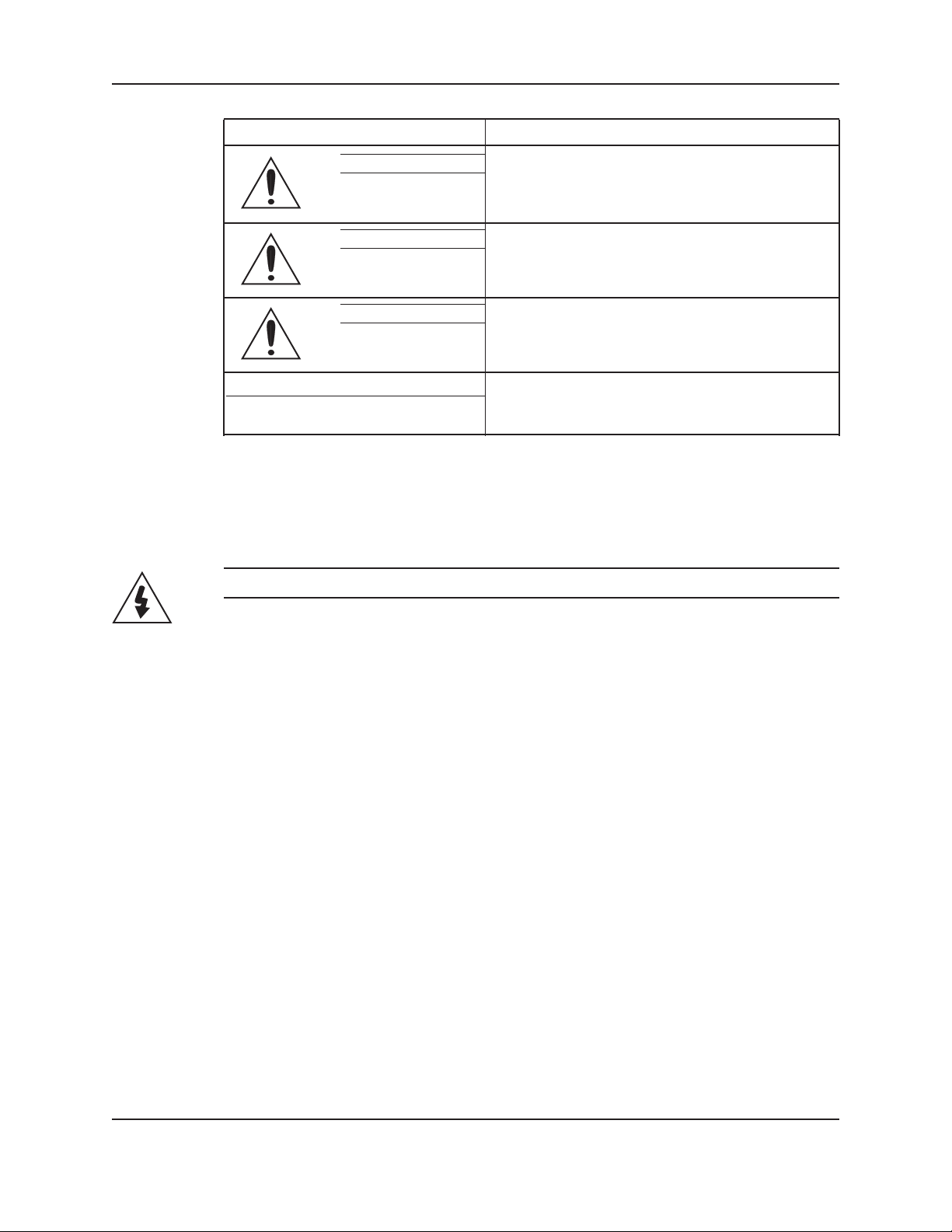
1.3.1 Hazard levels
Hazard level Indication
DANGER: A hazardous situation which, if not avoided, will
result in death or serious injury.
WARNING: A hazardous situation which, if not avoided, could
result in death or serious injury.
CAUTION: A hazardous situation which, if not avoided, could
result in minor or moderate injury.
NOTICE: • A potential situation which, if not avoided, could
result in undesirable conditions.
• A practice not related to personal injury.
1.3.2 Hazard categories
Hazard categories can either fall under hazard levels or let specic symbols replace the ordinary hazard level
symbols.
Electrical hazards are indicated by the following specic symbol.
Electrical Hazard:
These are examples of other categories that can occur. They fall under the ordinary hazard levels and may use
complementing symbols:
• Crush hazard
• Cutting hazard
• Arc ash hazard
1.4 Environmental safety
1.4.0 The work area
Always keep the station clean to avoid and/or discover emissions.
1.4.1 Waste and emissions regulation
Observe these safety regulations regarding waster and emissions:
• Appropriately dispose of all waste.
• Handle and dispose of the processed liquid in compliance with applicable environmental regulations.
• Clean up all spills in accordance with safety and environmental procedures.
• Report all environmental emissions to the appropriate authorities.
1.4.2 Electrical installation
For electrical installation recycling requirements, consult your local electric utility.
1.5 Recycling guidelines
Always follow local laws and regulations regarding recycling.
2
TECHNOFORCE Installation, Operation, and Maintenance
Page 9

1.6 User safety
1.6.0 General safety rules
These safety rules apply:
• Always keep the work area clean.
• Pay attention to the risks presented by gas and vapors in the work area.
• Avoid all electrical dangers. Pay attention to the risks of electric shock or arc ash hazards.
• Always bear in mind the risk of drowning, electrical accidents, and burn injuries.
1.6.1 Safety equipment
Use safety equipment according to the company regulations. Use this safety equipment within the work area:
• Helmet
• Safety goggles
• Protective shoes
• Protective gloves
• Gas mask
• Hearing protection
• First-aid kit
• Safety devices
NOTICE:
Never operate a unit unless safety devices are installed. Also see specic information about safety devices in other
chapters of this manual.
Introduction and Safety
1.6.2 Electrical connections
Electrical connections must be made by certied electricians in compliance with all international, national, state,
and local regulations. For more information about requirements, see sections dealing specically with electrical
connections.
1.6.3 Precautions during work
Observe these safety precautions when you work with the product or are in connection with the product:
• Never work alone.
• Always wear protective clothing and hand protection.
• Stay clear of suspended loads.
• Always lift the product by its lifting device.
• Beware of the risk of a sudden start if the product is used with an automatic level control.
• Beware of the starting jerk, which can be powerful.
• Rinse the components in water after you disassemble the pump.
• Do not exceed the maximum working pressure of the pump.
• Do not open any vent or drain valve or remove any plugs while the system is pressurized. Make
sure that the pump is isolated from the system and that pressure is relieved before you disassemble
the pump, remove plugs, or disconnect piping.
• Never operate a pump without a properly installed coupling guard.
TECHNOFORCE Installation, Operation, and Maintenance
3
Page 10

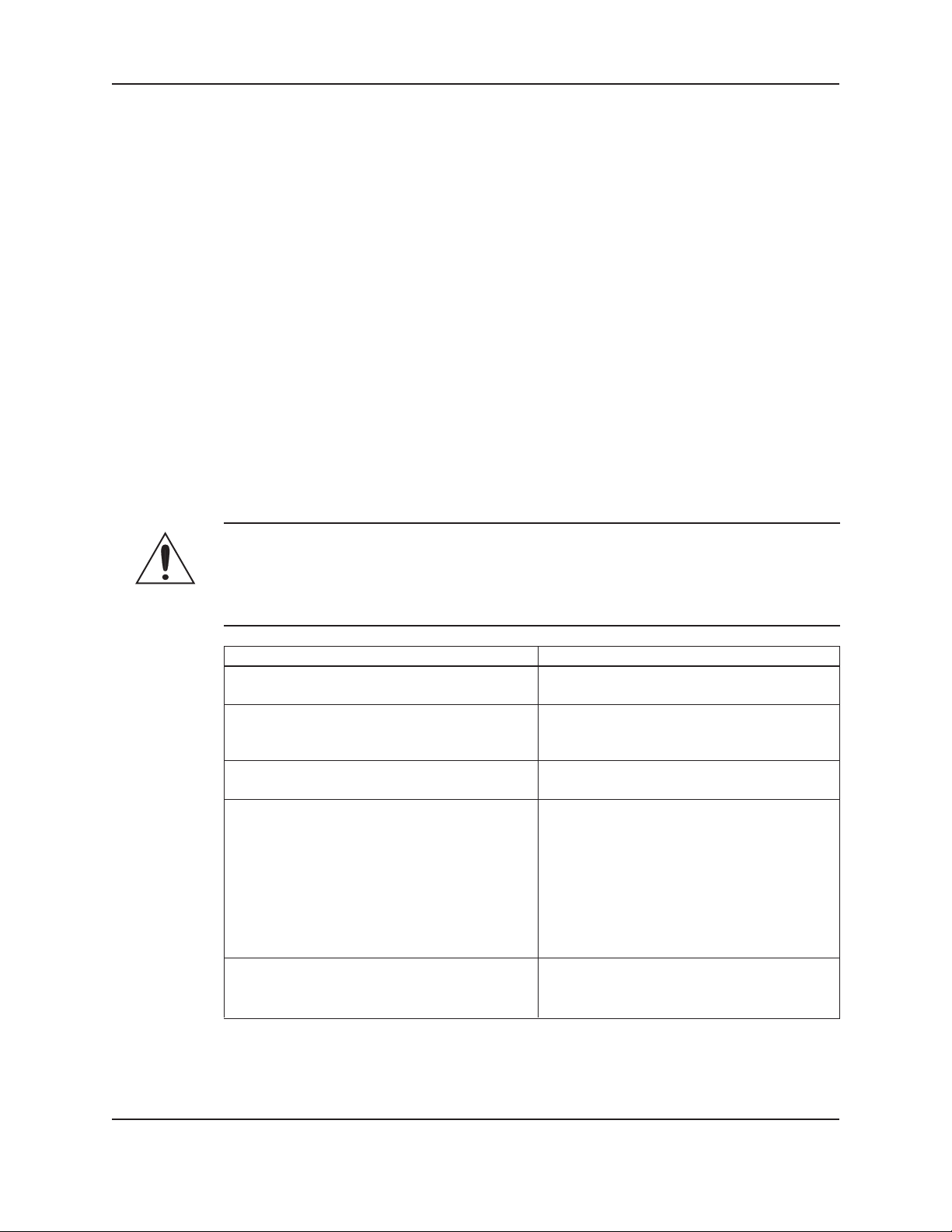
1.6.4 Wash the skin and eyes
Do the following if chemicals or hazardous uids have come into contact with your eyes or your skin:
If you need to wash Then . . .
your . . .
Eyes 1. Hold your eyelids apart forcibly with your ngers.
2. Rinse the eyes with eyewash or running water for at least 15 minutes.
3. Seek medical attention.
Skin 1. Remove contaminated clothing.
2. Wash the skin with soap and water for at least one minute.
3. Seek medical attentions, if required.
1.7 Product warranty
1.7.0 Coverage
Xylem undertakes to remedy faults in products from Xylem under these conditions:
• The faults are due to defects in design, materials, or workmanship.
• The faults are reported to an Xylem representative within the warranty period.
• The product is used only under the conditions described in this manual.
• The monitoring equipment incorporated in the product is correctly connected and in use.
• All service and repair work is done by Xylem-authorized personnel.
• Genuine Xylem parts are used.
• Only Ex-approved spare parts and accessories authorized by Xylem are used in Ex-approved products.
1.7.1 Limitations
The warranty does not cover faults caused by these situations:
• Decient maintenance
• Improper installation
• Modications or changes to the products and installation made without consulting Xylem
• Incorrectly executed repair work
• Normal wear and tear
Xylem assumes no liability for these situations:
• Bodily injuries
• Material damages
• Economic losses
1.7.2 Warranty claim
Xylem products are high-quality products with expected reliable operation and long life. However, should the need
arise for a warranty claim, then contact your Xylem representative.
Introduction and Safety
4
TECHNOFORCE Installation, Operation, and Maintenance
Page 11

2. Transportation and Storage
2.1 Inspect the delivery
2.1.0 Inspect the package
1. Inspect the package for damaged or missing items upon delivery.
2. Note any damaged or missing items on the receipt and freight bill.
3. File a claim with the shipping company if anything is out of order.
If the product has been picked up at a distributor, make a claim directly to the distributor.
2.1.1 Inspect the unit
1. Remove packing materials from the product.
Dispose of all packing materials in accordance with local regulations.
2. Inspect the product to determine if any parts have been damaged or are missing.
3. If applicable, unfasten the product by removing any screws, bolts, or straps.
For your personal safety, be careful when you handle nails and straps.
4. Contact your sales representative if anything is out of order.
2.2 Transportation guidelines
2.2.0 Lifting methods
Transportation and Storage
WARNING:
• Assembled units and their components are heavy. Failure to properly lift and support this
equipment can result in serious physical injury and/or equipment damage. Lift equipment only at
the specically identied lifting points. Lifting devices such as eyebolts, slings, and spreaders must
be rated, selected, and used for the entire load being lifted.
• Crush hazard. The unit and the components can be heavy. Use proper lifting methods and wear
steel-toed shoes at all times.
• Care should be taken to prevent damage due to dropping or jolting when moving the controller.
Transportation damage should be brought to the carrier’s attention immediately upon receipt.
2.3 Storage guidelines
2.3.0 Storage location
The product must be stored in a covered and dry location protected from extreme cold, heat, dirt, and vibrations.
NOTICE:
• Protect the product against humidity, heat sources, and mechanical damage.
• Do not place heavy weights on the packed products.
2.3.1 Long-term storage
If the controller is stored for more than 6 months, these requirements apply:
• Store in a covered and dry location.
• Store the unit free from heat, dirt, and vibrations.
• Recommended storage includes but not limited to a tarp over the unit.
Extended storage of VFDs may require special attention prior to start-up. See manufacturer’s IOM for
details.
TECHNOFORCE Installation, Operation, and Maintenance
5
Page 12

3. Product Description
3.1 General description
3.1.0 Description
The controller is a specic purpose programmable pump controller. This provides:
• Optimum pump control without the cost of general purpose control hardware.
• Software dedicated and established for the unit.
• Unique analog input protection of other members of the control family. In the event of a short
circuit condition, the current limit circuitry prevents failure of the analog input components.
NOTICE:
• Your controller should have a safety instruction decal. If the decal is missing or illegible, contact
your representative for a replacement.
3.2 Operational limits
3.2.0 Temperature and ventilation
All electrical equipment is susceptible to failure if operated in ambient temperatures outside of its rating. The
OPERATING temperature range for this unit is 0 to 40°C. The relative humidity should not exceed 90% noncondensing. The unit should not be operated outside these extremes.
Product Description
3.3 Nameplate information
3.3.0 Important information for ordering
Every pump station has a nameplate that provides information about the pump station. The pump station
nameplate is located on the inside of the control enclosure door.
When ordering spare parts, be prepared to identify the nameplate information when contacting the factory.
• Model
• Size
• Serial number
• Item numbers of the required parts
Model Number
Serial Number
Station Voltage
System FLA
SCCR
Largest Motor HP
Station Flow
Suction Pressure
Discharge Pressure
Pump Boost
Date Code
Residential & Commercial Water
Dallas, Texas, U.S.A
6
.
TECHNOFORCE Installation, Operation, and Maintenance
Page 13

Nameplate Data Explanation
Model Number The manufacturer’s number to indicate the particular type of product which
has been acquired.
Serial Number A set of characters that uniquely identies a single unit and can be used for
traceability and warranty purposes.
Station Voltage The rated voltage at which the station has been designed for. Should match the
application site supply voltage.
System FLA The full-load-amperage at which the station can operate.
SCCR “Short-Circuit Current Rating”. Represents the maximum level of short-circuit
current that a component or assembly can withstand.
Largest Motor HP The rated HP for the largest Pump in the system.
Station Flow The designed duty point, in GPM, LPH, etc.
Suction Pressure The line pressure on the input side of the pump station.
Discharge Pressure The line pressure on the output side of the pump station.
Pump Boost The difference between the input side of the pump station and the output side
of the pump station.
Date Code Marking of products to indicate their date of manufacture.
3.4 Main parts and functions
Product Description
3.4.0 Input voltage
The VFD and TechnoForce Pump Controller can be set up to operate across a broad range of voltages. It was
factory set to operate on the voltage shown on the nameplate. Check the VFD nameplate for the proper input
and output voltages before wiring the VFD.
The voltage tolerance is +10/-5% and phase to phase voltage must not have an imbalance greater than 5 VAC.
3.4.1 Ground connections
A grounding terminal is provided for a dedicated ground wire connection. All provisions of the National Electrical
Code and local codes must be followed.
WARNING:
• Conduit grounds are not adequate. A separate ground wire must be attached to the ground lug provided in
the enclosure to avoid potential safety hazards.
3.4.2 Power wiring
Power wire types and sizes must be selected based upon conformance with the National Electrical Code and all
local codes and restrictions. In addition, only copper (Cu) wire rated for 75°C (minimum) may be used for the
power connections. Refer to the input current as listed on the nameplate afxed to the enclosure door when
sizing wire.
3.4.3 Output/motor disconnect
It is necessary that any device which can disconnect the motor from the output of the VFD be interlocked to the
emergency shutdown circuits of the VFD. This will provide an orderly shutdown if the disconnecting device is
open circuited while the VFD is in operation. Failure to provide this interlock may result in damaged components
due to improper installation.
CAUTION:
• Metal lings can create electrical short circuits. Do not drill, saw, le or perform any operation
on the VFD conduit entry plate while attached to the VFD.
TECHNOFORCE Installation, Operation, and Maintenance
7
Page 14

Product Description
3.4.4 Analog signals
Shielded cable (#22 AWG, Belden type 8762, Alpha #2411, or equal) should be installed for all D.C. control
wiring. The shield must be terminated in the Controller panel. Do not connect the shield at the other end of the
cable! Insulate the shield so that no electrical connection is made at the other end of the cable. A twisted pair of
#22 AWG conductors (Belden 8442, or equal) can be used in place of shielded cable. The cable length must be
limited to 5,000 feet for #22 AWG wire.
3.4.5 Field connection diagrams
Refer to the pump Installation, Operation, and Maintenance Manual for specic details unique to the pump.
Refer to the ow sensor/transmitter Installation, Operation, and Maintenance manual for specic details unique to the
ow sensor/transmitter.
Job specic wiring and dimensional drawings and typical eld connection diagram should be reviewed prior to unit
installation and operation.
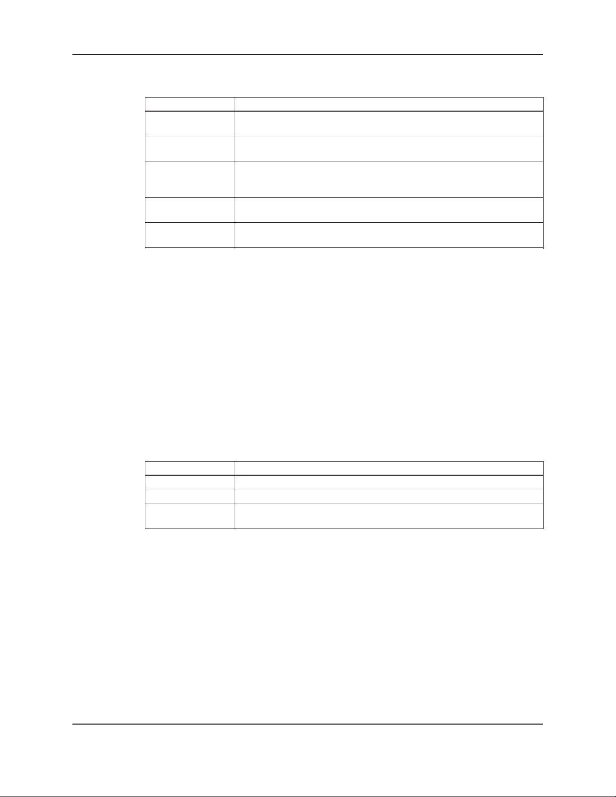
3.5 Glossary of terms
VFD Variable Frequency drive; converts a constant power input into a variable power output for the motor;
a device for controlling motor speed.
Alternation Process of determining which pump will serve as lead pump and which pump will serve as lag pump.
Destage To turn off a lag pump.
EOC End of curve; point at which a pump is staged or destaged.
Lag pump Standby pump which activates only when lead pump alone cannot efciently provide sufcient
pressure or ow rate.
Lead pump Duty pump which runs continuously until a standby pump is required.
LED Light emitting diode, located on OIP and controller.
OIP Operator Interface Panel.
PID Proportional Integral Derivative; 3 variables required for error control.
PV (Process Signal generated by a sensor which is set up to control the system.
Variable)
Proof timer Minimum time period before controller acknowledges an input; time period for which a signal must
be stable before it is accepted by the controller as a sustained and valid signal.
RTC Real time clock.
Stage To start a lag pump.
SP Set point.
HD Hard Deck.
8
TECHNOFORCE Installation, Operation, and Maintenance
Page 15
4. Installation
4.1 Field connections
4.1.0 Diagrams
Review the wiring diagrams and dimensional drawings before you install and operate the unit.
4.1.1 Electrical precautions
WARNING:
• Prevent electrical shocks. Disconnect the power supply before beginning installation. FAILURE
TO FOLLOW THESE INSTRUCTIONS COULD RESULT IN SERIOUS PERSONAL INJURY,
DEATH AND/OR PROPERTY DAMAGE.
• Each motor must have a properly sized drive. Ground fault protection should be sized properly.
Refer to local electrical codes for sizing and selection.
• Refer to the motor manufacturer’s IOM for specic installation information.
• Motor can start automatically. Keep hands away from output shaft until motor is completely
stopped and input power is removed from the motor control panel. Lockout main power switch
while working near motor shaft.
• The use of motor disconnect switches is acceptable. Consult the factory for proper interlocking
with variable frequency drives.
• Motor control equipment and electronic controls are connected to hazardous line voltages.
When servicing electronic controls, there will be exposed components at or above line potential.
Extreme care should be taken to protect against shock. Stand on an insulating pad and make
it a habit to use only one hand when checking components. Always use accurate test meters
when checking electrical components. Always work with another person in case of an emergency.
Disconnect power when performing maintenance. Be sure equipment is properly grounded. Wear
safety glasses whenever working on electronic control or rotating equipment.
Installation
DANGER:
• Troubleshooting live control panels exposes personnel to hazardous voltages. Electrical
troubleshooting must only be done by a qualied electrician. FAILURE TO FOLLOW THESE
INSTRUCTIONS COULD RESULT IN SERIOUS PERSONAL INJURY, DEATH, AND/OR
PROPERTY DAMAGE.
4.2 Earth (ground connections)
WARNING:
• Conduit grounds are not adequate. A separate ground wire must be attached to the ground lug
provided in the enclosure to avoid potential safety hazards. Failure to follow these instructions
could result in serious personal injury or death, property damage.
A grounding terminal is provided for a dedicated earth (ground) wire connection. You must follow all provisions
of the National Electrical Codes and local codes.
4.3 Sensor and control wiring
The following sections are based on the installation of standard TechnoForce product. Because of customized
software and hardware, the installing contractor should base all wiring connections on the wiring diagrams that
accompany each controller. These sections are meant to complement, not replace, those wiring diagrams.
TECHNOFORCE Installation, Operation, and Maintenance
9
Page 16
Differential pressure switches are installed to sense the increase in pressure between the pump suction and
discharge gauge taps and are used to determine whether a pump is running. Each switch should be wired from
the normally closed contact.
To control variable frequency drives it is necessary to wire RS485 with each VFD.
With certain bypass and control methods it is necessary to disable the adjustable frequency drive from running.
This is accomplished by wiring from the terminals to each VFD’s interlock terminals. Should this wiring be
required, any jumpers which may be found on the VFD’s interlock terminals should be removed.
The control family may be provided with the capability to accept many analog inputs. Typically all analog inputs
must be 4-20mA and powered by the 24VDC power supply in the controller. All shields must be grounded in the
controller only to prevent ground loops and improper signals.
Hardwire communications refers to the capability of the Controller to communicate with an energy management
system. Standard communication features are listed below:
Remote Start/Stop – Remove the jumper from Terminal 200 and install a switch as indicated on the wiring
diagram. CLOSED CONTACT of this switch will provide the start signal.
Remote Alarm Indication – A digital output rated 2.5 AMPs at 240V is supplied. This output closes to indicate
an alarm condition exists.
User Congurable I/O – The Controller comes equipped with the capability to dene the operation of any
unused input or output signal. Refer to System Set Up I/O menus.
4.4 Pump package location guidelines
Installation
WARNING:
• Assembled units and their components are heavy. Failure to properly lift and support this equipment can
result in serious physical injury and/or equipment damage. Lift equipment only at the specically identied
lifting points. Lifting devices such as eyebolts, slings, and spreaders must be rated, selected, and used for the
entire load being lifted.
Guideline Explanation
Make sure that the space around the pump This facilitates ventilation, inspection,
package is sufcient. maintenance, and service.
If you require lifting equipment such as hoist or This makes it easier to properly use the lifting
tackle, make sure that there is enough space above equipment and safely remove and relocate the
the pump package. components to a safe location.
Protect the unit from weather and water damage This is applicable if nothing else is specied.
due to rain, ooding, and freezing temperatures.
Do not install and operate the equipment in closed Acceptable devices:
systems unless the system is constructed with • Pressure relief valves
properly-sized safety devices and control devices. • Compression tanks
• Pressure controls
• Temperature controls
• Flow controls
If the system does not include these devices,
consult the engineer or architect in charge before
you operate the pump.
Take into consideration the occurrence of The best pump location for noise and vibration
unwanted noise and vibration. absorption is on a concrete oor with subsoil
underneath.
10
TECHNOFORCE Installation, Operation, and Maintenance
Page 17

4.5 System piping and unit installation – nal checklist
1. Check that the unit base is properly leveled, grouted and secured.
2. Check that all lubrication points are properly lubricated per motor manufacturer’s instructions.
3. Check that the shut-off valves to the transmitters open.
4. Check that the shut-off valves to the pump suction open.
5. Check that the shut-off valves to the discharge line open.
6. Check that the piping is properly supported to prevent strains on the unit.
7. Check that the system, including pumps and valving, are purged of debris and air.
CAUTION:
• Seal damage may occur. Do not run pumps dry. Fill and vent the pump volute prior to operation.
FAILURE TO FOLLOW THESE INSTRUCTIONS COULD RESULT IN PROPERTY DAMAGE
AND/OR MODERATE PERSONAL INJURY.
4.6 Electrical wiring and control settings – nal checklist
1. Check the unit nameplate or motor terminal connection to ensure the feeder line voltage
corresponds to the unit voltage
WARNING:
• Electrical shock hazard. Inspect all electrical connections prior to powering the unit. Wiring connections
must be made by a qualied electrician in accordance with all applicable codes, ordinances, and
good practices. FAILURE TO FOLLOW THESE INSTRUCTIONS COULD RESULT IN SERIOUS
PERSONAL INJURY, DEATH, AND/OR PROPERTY DAMAGE.
Installation
2. Check that feeder wires are correctly sized for the load.
3. Check that the fuses are correctly sized. They must not exceed 1.75 times the full load current of
the motor. Usual sizing is 1.15 to 1.5 times the full load current.
DANGER:
• High voltage 3 phase power can kill. Disconnect and lockout power prior to servicing. FAILURE TO
FOLLOW THESE INSTRUCTIONS COULD RESULT IN SERIOUS PERSONAL INJURY, DEATH,
AND/OR PROPERTY DAMAGE.
WARNING:
• Conduit grounds are not adequate. A separate ground wire must be attached to the ground lug provided in
the enclosure to avoid potential safety hazards. FAILURE TO FOLLOW THESE INSTRUCTIONS
COULD RESULT IN SERIOUS PERSONAL INJURY, DEATH, AND/OR PROPERTY DAMAGE.
4. Check that the unit is properly grounded.
5. Make sure all the power terminals in the control panel have been tightened.
TECHNOFORCE Installation, Operation, and Maintenance
11
Page 18

4.7 Operator interface panel
4.7.0 Diagrams
The OIP consists of a 4 x 20 character LCD screen and a 26 button keypad with LEDs which display system
status.
Installation
4.7.1 Key functionality
The names of the keys on the Operator Interface Panel (OIP) are shown as CAPITAL LETTERS in this
manual. Table 1 shows the functionality of the keys on the OIP.
12
TECHNOFORCE Installation, Operation, and Maintenance
Page 19

4.7.2 Table 1 Key Functionality
Key Name Functionality
START/STOP Starts or stops the system.
AUTO/ MANUAL Toggles the operation mode. The system must be stopped to change the
operation mode.
PUMP 1-6 ENABLE Enables or disables the corresponding pump. Pumps cannot be disabled
while they are failed.
RESET/ SILENCE This key is used to reset alarms and events. When the A/V Alarm relay
output is set. Pressing of this key resets the alarms and events.
HELP Press the HELP button, from the status screens, to view alarms or events
while the HELP LED is ashing. While in the Alarm screen, press the HELP
button again to view help messages for active alarms. Press HELP any other
time to view screen specic help messages.
PV/1 Press PV from the status screens, to bring up the process variable screen
SETPT/2 Press SET PT from the status screens, to bring up the set point menu shown in
section 5.5
SETUP/3 Press SETUP, from the status screens, to bring up the Setup Menu shown in
section 4.10
ALT/4 Press ALT, from the status screens, to manually alternate the pump staging
sequence.
LOG/5 Press LOG, from the status screens, to bring up the Log Menu, shown in
section 6.14.0
YES/7 Press YES at OK prompts to accept values and proceed
INFO/8 Press INFO, from the status screens, to bring up the program type and version
number shown in section 6.14
NO/0 Press NO at OK prompts to edit the parameters
ENTER Conrms entries
CLEAR Clears entries or used to exit some screens
PREV/( ) Navigates to neighboring screens
NEXT/( ) Navigates to neighboring screens
UP (▲) Used to modify values and navigate to neighboring screens
DOWN (▼) Used to modify values and navigate to neighboring screens
Note: Setting the display contrast.
The Contrast on the display is set at the factory. However, the user can make a different
contrast setting as desired. To do this press “Enter”. while holding down this key, the “UP” and
“DOWN” key can be used to set contrast.
ENTER + UP... increase contrast
ENTER + DOWN... reduce contrast
▲
Installation
▲
TECHNOFORCE Installation, Operation, and Maintenance
13
Page 20
4.8 LEDs
4.9 I/O
4.9.0 Analog Inputs
4.9.1 Digital Inputs
Installation
Table 2 gives the meaning of the LED states.
LED Description
START/STOP On = Start
Off = Stop
AUTO/ MANUAL On = Auto
Off = Manual
PUMP 1-6 On = Pump On
Off = Pump Disabled
Blink = Pump Ready, Blink Fast = Pump Failed
RESET/ SILENCE Off = OK
Blink = Reset Required
HELP Off = OK
Blink = Event/Alarm(press HELP from the status screens to view)
The TechnoForce Pump Controller is equipped with 4 analog input channels. The analog inputs must provide
a 4-20mA signal. Typically, analog inputs will be powered by the 24V power supply within the panel. For analog
inputs which source their own power, consult factory.
Shielded 22 AWG cable should be installed for all analog input wiring. The shield must be terminated in the
TechnoForce Pump Controller. Do not connect the shield at the other end of the cable! Insulate the shield so
that no electrical connection is made at the other end of the cable. A twisted pair of #22 AWG conductors can
be used in place of shielded cable. The cable length must be limited to 2,500 feet for #22 AWG wire.
The TechnoForce Pump Controller is equipped with (12) 24VDC digital input channels. This signal voltage must
be obtained from the 24VDC power supply mounted to the subpanel. It is not recommended that other power
sources be used without factory approval. All digital inputs are automatically assigned based on Table 3. See the
typical wiring diagram in Appendix.
Table 3: Digital Inputs Functionalities
Functionality DI # Description
Start/Stop Sw 1 Remote contact can be used to start/stop the system.
DP 1-6 2-7 Differential pressure switches
Optional DI 8-12 User can select the function of optional input in IO setup, see
section 4.10.17.
# 22 AWG cable should be installed for all eld wiring to digital inputs.
4.9.2 Digital Output Module
The digital output consists of 1 normally open and 1 normally closed contact for each output rated at 2.5A at
240V. Customer connections are made directly to the terminals mounted on the digital output module. Refer to
section 4.10.17 for relay output setup.
14
TECHNOFORCE Installation, Operation, and Maintenance
Page 21

4.10 Set up & features
Note: Many sections of the Set up & Features show a path for navigation. An example is shown below to
understand the given path.
Example for system setup path.
Path: Status Screen / Setup(3) / System(3)
To follow the above path press the SETUP/3 key from the system status screen. Then press the SETUP/3 key
for number 3 which is a selection number for system and press ENTER key. It will lead to the system setup
screen.
Upon powering up the controller, the display will light and show the following screen:
<TECHNOFORCE PUMP>
CONTROLLER
MM/DD/YY HH:MM:SS A/P
STOP MANUAL NORM
The current date and time will be displayed on the third line.
Press the SETUP/3 key once and the following MAIN SET UP menu items will be displayed:
SELECTION: # 0=EXIT
1 = SENSORS 4 = TEST
2 = PUMPS 5 = ALRM/EVT
3 = SYSTEM 6 = Q-START
Installation
4.10.0 Sensor Setup
Press the PV/1 key at the Main Set Up menu display. Then press the ENTER key.
The SENSOR SET UP MENU will be displayed as shown below:
AI 1 TYPE: $$$
SPAN= ### ZERO= ##
< OK $ (Y/N) >
To accept the current values, press YES/7 key and then press the ENTER ke y.
To set up each eld, press the NO/0 key and then press the ENTER key.
The current TYPE eld starts blinking. Press the up (▲) and down (▼) keys to navigate to the desired TYPE
and then press the ENTER key to conrm selection.
The following selections are valid:
SYS (System Pressure)
SUC (Suction Pressure)
RESYS (Redundant System Pressure)
FLOW (System Flow)
PRESS (For Monitor only)
NONE
If RESYS is selected as a desired eld, the following screen will get displayed:
ACTIVE SENSOR ##
DRIFT THRESHOLD ##%
DRIFT PR TM ###s
OK $ (Y/N)
TECHNOFORCE Installation, Operation, and Maintenance
15
Page 22

Installation
RESYS MENU ITEMS
Menu Item Variable Default Range Field
Value
RESYS Active Sensor : ## 1 1-4
Enter the active system pressure sensor number
Drift Threshold: ##% 5 0-100
Pressure difference limit between the active and
redundant pressure sensor in %
Drift Pr Tm : ##s 0 0-999
Proof timer prior to give warning when exceed the
drift threshold limit, in seconds
To set up each eld, press the NO/0 key and then press the ENTER key.
The ACTIVE SENSOR eld will start blinking. Change the current value in Active Sensor eld by pressing
desired numeric Keys and then press ENTER key to conrm.
Press ENTER key to accept the current DRIFT THRESHOLD value. To change the value in DRIFT
THRESHOLD eld, press the desired Numeric Keys and then press ENTER to conrm.
Press ENTER key to accept the current value of DRIFT PR TM. To change the value in DRIFT PR TM
eld press the desired Numeric Keys and then press ENTER to conrm.
To accept the current values, press YES/7 key and then press ENTER key. The screen will go back to the
SENSOR SET UP menu displayed above.
Press the NEXT/( ) key if additional sensors need to be set up. Repeat the above steps for all remaining
sensors.
Pressing YES/7 key and then the ENTER key at the SENSOR SET UP screen will take the display back to
the MAIN SET UP screen.
▲
4.10.1 Pump set up
Paths: Status Screens / Set up(3)
Press the SET PT/2 key at the Main Set Up menu screen. Then press the ENTER key.
The PUMP SET UP MENU will get displayed as shown below:
SELECTION: # 0= EXIT
1 = NUMBER OF PUMPS
2 = PUMP NAMEPLATE
3 = RESET PUMP TIME
To change the values in NUMBER OF PUMPS eld, press PV/1 key then press the ENTER key. The
following menu will get displayed:
TOTAL PUMPS: #
STANDBY PUMPS: #
OK $ (Y/N)
To set up each eld, press the NO/0 key and ENTER key. Modify the values as desired using the appropriate
numeric key. The pump number is limited to the maximum number of pumps.
To accept the current values, press YES/7 key and then press ENTER ke y.
The screen will go back to the PUMP SET UP MENU display.
To change the values in PUMP NAMEPLATE eld, press SET PT/2 key then press the ENTER key. The
following menu will get displayed:
<PUMP 1 NAMEPLATE>
AMPS: ###.# HP: ###.#
VOLTS: ### Hz: ##
Spd: #### OK $ (Y/N)
16
TECHNOFORCE Installation, Operation, and Maintenance
Page 23

Installation
To set up each eld, press the NO/0 key and ENTER key. Modify the values as desired using the appropriate
keys. Modify the values as desired for pump 1.
Note: For example, to enter a value of 3.5 Amps, go to the amps eld, press numerical key 3 and
press enter. Then press key 5 and enter.
To change the values for other pumps, press the NEXT/( ) key. This is only applicable if the total numbers of
pumps selected in TOTAL PUMPS: # eld are more than 1.
Note:
All values will be copied to the next screen by pressing NEXT/( ) key. They will only be copied the rst time
the screens are visited. To edit the values, press the NO/0 key and ENTER key. Modify the values as desired.
To conrm the modied values, press YES/7 key and then press ENTER ke y.
The screen will go back to the PUMP SET UP MENU display.
To change the values in RESET PUMP TIME eld, press the SETUP/3 key then press the ENTER key. The
following menu will get displayed:
RESET PUMP TIME?
P1: N P2: N P3: N
P4: N P5: N P6: N
OK $ (Y/N)
To reset the pump(s) run time, press NO/0 key and ENTER.
By default, N will be displayed next to the pump elds (P1: , P2: etc.) depending upon number of pumps
selected. N corresponding to P1: eld will start blinking. To reset the pump run time for pump 1, press the
YES/7 key and ENTER. Similarly modify the values for the rest of the pumps as applicable.
Note: This selection is only valid for the pumps selected. For example, if the number of pumps selected is 2, the
following screen will get displayed:
RESET PUMP TIME?
P1: N P2: N P3: N/A
P4: N/A P5: N/A P6: N/A
OK N (Y/N)
To conrm all the selections made, press YES/7 key and then press ENTER key. The screen will go back to the
PUMP SET UP MENU display.
Pressing the NO/0 key and then ENTER key at the PUMP SET UP screen will take the display back to the
MAIN SET UP screen.
▲
▲
4.10.2 System set up
Paths: Status Screens / Set up(3)
Press the SETUP/3 key at the Main Set Up menu screen. Then press the ENTER ke y.
The rst screen will get displayed as shown below:
< SELECTION: # >
1 = STAGE/DESTAGE
2 = VFD
3 = EXERCISE 0 = EXIT
Press the NEXT/( ) key to go to the next screen. The display now shows:
< SELECTION: # >
4 = ALTERNATION 5=PID
6 = RESET TOTALS
7 = DATE, TIME 0 = EXIT
Press the NEXT/( ) key to go to the next screen. The display now shows:
< SELECTION: # >
8 = PASSWORD 0 = EXIT
TECHNOFORCE Installation, Operation, and Maintenance
▲
▲
17
Page 24

9 = I/O SETUP
10 =COMMUNICATIONS
Press the NEXT/( ) key to go to the next screen. The display now shows:
< SELECTION: # >
11 = SPECIAL FUNCTIONS
12 = SAVE/LOAD
13 = DISPLAY 0 = EXIT
Pressing the NEXT/( ) key again will take the screen back to the rst screen.
Use the appropriate numeric key to select the desired menu, then press the ENTER key. A detailed description
of each menu follows. For example, to select the STAGE/DESTAGE menu, press the PV/1 key and then press
the ENTER ke y.
4.10.3 Stage/ destage menu
Paths: Status Screens / Set up(3) / System(3) / StageDestage(1)
The rst screen has been displayed below:
< SELECTION: # >
1 = PV STAGE 0=EXIT
2 = PV DESTAGE
3 = EOC STAGE
Press the NEXT/( ) key to go to the next screen.
The display now shows:
< SELECTION: # >
4=EOC DESTAGE 0=EXIT
5=FLOW DESTAGE
6=POWER LIMIT STAGE
By pressing the appropriate numeric key and ENTER key, the setup can be completed.
See the following table for all STAGE/DESTAGE menu items.
Menu Item Variable Default Range Field
Value
PV Stage Stg Spd: ##% 95 0-100
The maximum speed at which the lead pump will
operate prior to starting a lag pump, %.
Stg Proof Timer: ### s 30 0-999
Proof timer prior to starting lag pump, seconds.
Stab Timer: ###s 60 0-999
Staging stabilization time, delay prior to calculating
destage value, seconds.
▲
▲
▲
STAGE/DESTAGE SETUP MENU ITEMS
Installation
18
TECHNOFORCE Installation, Operation, and Maintenance
Page 25

Installation
STAGE/DESTAGE SETUP MENU ITEMS (continued)
Menu Item Variable Default Range Field
Value
PV Destage Destage: ###% 85 0-100
Enter the percentage of the stabilized speed at which
the lag pump will stop, %.
Destg Pr Timer: ### s 30 0-999
Proof timer prior to stopping lag pump, seconds.
HD Spd: ### % 50 0-100
The lowest speed at which parallel pumps will operate
prior to destaging the lag pump, %. It must be
greater or equal to minimum frequency.
HD Pr Tm: ### s 30 0-999
The proof timer prior to destaging the lag pump when
operating below the HD speed, seconds.
EOC Stage Pump Max Flow: ##### 0 0-65,
(Flow meter The maximum allowable ow in GPM prior to starting a
required) lag pump. A value of 0 disables this function.
Stg Proof Tm: ###s 30 0-999
Proof timer prior to end of curve staging, seconds.
EOC Destage Destage Flow: ### % 45 0-100
(Flow meter Enter the percent of stabilized ow at which the lag
required) pump is destaged, %.
Destage Pr TM: ###s 30 0-999
Proof timer prior to destaging lag pump, seconds.
Flow DeStage Flow Destage: #####GPM 0 0-65,
The total ow above which the lag pump will be
forced to destage. A value of “0” disables this function
De-Stage Pr Tm: ###s 30 0-999
Proof timer prior to Flow destaging lag pump in seconds
Force Destg Tmr: ###m 0 0-999
The time after which the lag pump will be forced
to destage. A value of “0” disables this function
Power Limit Enable Power Stage N Y/N
Stage Limit $ (Y/N)
Exit: $(Y/N)
Reads motor current entered in pump set up to stage on
next pump after a xed time delay should current limit
be reached.
535
535
4.10.4 VFD menu
Paths: Status Screens / Set up(3) / System(3) / VFD(2)
The rst screen has been displayed below:
<Selection:# >
1 = VFD Setup
2 = VFD Set Parameter
3 = VFD Read Parameter
Press the NEXT ( ) key to go to the next screen.
The display now shows:
<Selection: # >
4 = All SYS SEN Fail
TECHNOFORCE Installation, Operation, and Maintenance
▲
19
Page 26

Installation
Use the appropriate numeric key to select the desired menu, then press the ENTER key. See the following table
for all VFD menu items.
VFD Menu Items
Menu Item Variable Default Range Field
Value
VFD Setup Accel Tm: ## 5 0-1800
Drive acceleration time in seconds from zero to
maximum frequency ramp
Decel Tm: ## 5 0-1800
Drive acceleration time in seconds from maximum to
zero to maximum frequency ramp
Freq Max : ## 60 0-60
Enter the maximum limit for the drive output frequency
Freq Min : 30
Enter the minimum limit for the drive output frequency
VFD Set VFD: # 0 0-65,
Parameter The VFD number in which the parameter needs to be set. 535
ADDRESS:
Enter the parameter code from the parameter list
available in the ABB user’s manual supplied.
RESOLUTION: #
Enter the value of parameter “Resolution” from the
parameter list available in the ABB user’s
manual supplied.
VALUE:
Enter the desired parameter value.
VFD Read VFD: # 0 0-65,
Parameter The VFD number from which the parameter needs
to be read.
ADDRESS:
Enter the parameter code from the parameter list
available in the ABB user’s manual supplied.
RESOLUTION: #
Enter the resolution from the parameter list available
in the ABB user’s manual supplied.
OFFSET:
Enter the lower limit of the parameter “Range” from
the parameter list available in the ABB user’s
manual supplied.
READ:
Press YES/7 key and ENTER key to read the
parameter values
All Sys Sen PUMP SPEED: 100 0-100
Fail Enter the % speed for the drive(s) to operate at in the
event that all system sensor fail.
NO OF PUMP RUN: 1 1-6
Enter the number of pumps that should operate at the
above speed in the event that all system sensor fail.
535
20
TECHNOFORCE Installation, Operation, and Maintenance
Page 27

Note:
1. Use the (▲) and (▼) keys to select the appropriate resolution values
2. Use the Next/( ) key and Prev/( ) key to select the desired sign(+ or -) for VALUE and OFFSET
variables
4.10.5 Exercise menu
Paths: Status Screens / Set up(3) / System(3) / Exercise(3)
See the following table for all EXERCISE menu items.
Menu Item Variable Default Range Field
Value
EXERCISE Period : #Hrs 0 0-999
Amount of time between automatic exercising of the
pumps, in seconds. A value of 0 disables pump exercising
Duration : ###s 0 0-999
Amount of time pumps will be exercised, all pumps
which have not run in the last period will be exercised
simultaneously
Pump exercising will ensure that no pumps go for long periods of time without running. Note that automatic
alternation can also provide this functionality. Pump exercising will only occur when the system is started and in
automatic operation. All pumps which need exercising will exercise on startup.
▲
▲
Exercise Menu Items
Installation
4.10.6 Alternation menu
Paths: Status Screens / Set up(3) / System(3) / Alternation(4)
The following ALTERNATION menu options are available:
4.10.7 Timed auto alternation
See the following table for TIMED AUTO ALTERNATION menu items.
Timed Auto Alternation Menu Items
Menu Item Variable Default Range Field
Value
Timed Auto Period: #Hrs 168 0-999
Alt Time between pump alternations when using “Timed
Auto Alternation”, in hours. A value of 0 will disable
this function
Duration: ###s 10 0-99
Amount of time that the running pumps will remain on
during alternation, in seconds
4.10.8 Scheduled auto alternation menu
See the following table for SCHEDULED AUTO ALTERNATION menu items.
Scheduled Auto Alternation Menu Items
Menu Item Variable Default Range Field
Value
Scheduled Scheduled Alt: 0 0-3
Auto Alt Pump alternates based on the “Period” selected -
Daily: alternates daily based on the “Time”;
Weekly: alternates weekly based on the “Day” and
“Time”;
Monthly: alternates monthly based on the “Day” and
“Time”.
Note: At any time, only one of the 3 period based variables can be enabled.
TECHNOFORCE Installation, Operation, and Maintenance
21
Page 28

4.10.9 Daily alternation
The Daily Alternation screen is displayed below:
Daily
Alt. Time: HH:MM
Enable: $ (Y/N)
OK? $(Y/N)
To edit the alternation time, press the NO/0 key and ENTER key. Modify the values as desired.
Enter the Alternation Time in 24Hr format (range being 0:00-23:59) at which pumps will alternate daily. Press
YES/7 key to enable Daily alternation. Press the YES/7 key again to conrm the selection.
4.10.10 Weekly alternation
The Weekly Alternation screen is displayed below:
Alt. Day of week: #
1=Mon...7=Sun
Time HH:MM (0-23)
Enable: $(Y/N)
OK? $(Y/N)
To edit the displayed values, press the NO/0 key and ENTER key. Modify the values as desired.
Enter the Alternation Day of Week (1= Monday…….7=Sunday) on which the pumps will be alternated.
Enter the Alternation Time in 24Hr format (range being 0:00-23:59).
Press YES/7 key to enable Monthly alternation. Press the YES/7 key again to conrm the selection.
Installation
4.10.11 Monthly alternation
The Monthly Alternation screen is displayed below:
Alt. Day of Month: #
(1-31)
Time HH:MM (0-23)
Enable: $(Y/N) OK? $(Y/N)
To edit the displayed values, press the NO/0 key and ENTER key. Modify the values as desired.
Enter the Alternation Day of Month (1, 2, 3, 4….31 etc.) on which the pumps will be alternated.
Enter the Alternation Time in 24Hr format (range being 0:00-23:59).
Press YES/7 key to enable Monthly alternation. Press the YES/7 key again to conrm the selection.
If 29,30 or 31 is entered as the day, the sequence will automatically alternate on the last day of the month.
Note:
In case Timed Auto Alt is in enabled state and Scheduled Auto Alt also gets enabled, Timed Auto Alt will get
disabled and a warning message “Timed Alteration will be disabled” will be displayed on the screen. Press
CLEAR key to go back to the ALTERNATION menu.
22
TECHNOFORCE Installation, Operation, and Maintenance
Page 29

4.10.12 Alternation basis
See the following table for ALTERNATION BASIS menu items.
Menu Item Variable Default Range Field
Value
Alternation 1=Pump Sequence 1 1-2
Basis (The next pump in sequence will become the lead pump
after alternation)
2=Pump Run Time
(The pump with the lowest run time will become the
lead pump after alternation)
4.10.13 PID menu
Paths: Status Screens / Set up(3) / System(3) / PID(5)
See the following table for all PID menu items.
Menu Item Variable Default Range Field
Value
PID PID-P ### 300 0-999
Enter the desired proportional value.
PID-I ### 1 0-999
Enter the desired integral value.
PID-D ### 15 0-999
Enter the desired derivative value.
SP Deviation ### 0 0-999
Enter the value for the number of PV units at which a
dead band will be created around the setpoint. The PID
will be modied within the dead band per the index
setting below.
Index ### 0 0-999
Enter a value to buffer the response of the PID while
operating in the dead band dened above.
Index = 1 (no impact)
Index = 999 (maximum buffer.)
Start Up ## 5 0-60
Start up delay in seconds
Installation
Alternation Basis Menu Items
PID Menu Items
4.10.14 Reset totals menu
Paths: Status Screens / Set up(3) / System(3) / Reset Totals(6)
See the following table for all RESET TOTALS menu items
Reset Totals Menu Items
Menu Item Variable Default Range Field
Value
RESET RESET TOTAL KW-HRS $ N Y or N
TOTALS Press YES/7 key and ENTER key to reset the total
KW-HRS
RESET TOTAL FLOW $ N Y or N
Press YES/7 key and ENTER key to reset the total Flow
TECHNOFORCE Installation, Operation, and Maintenance
23
Page 30

4.10.15 Date, time menu
Paths: Status Screens / Set up(3) / System(3) / Date, Time(7)
See the following table for all DATE, TIME menu items
Date, time Menu Items
Menu Item Variable Default Range Field
Value
Date/Time MM
Enter the current month using both digits,
example Jan. should be entered as 01.
DD
Enter the current date using both digits, example
the 6th should be entered as 06.
YYYY
Enter the current year using all 4 digits.
HH
Enter the hours using the 24 hour format,
example 9:00 p.m. should be entered as 21.
MM
Enter the minutes using both digits.
Display 24 Hour Fmt: ? (Y/N) N Y or N
Press YES/7 key and ENTER key to display the
time in the 24 hour format. Press NO/0 key and
ENTER key to display the time in
AM/PM format.
Daylite Savings Tm: ?(Y/N) N Y or N
Press YES/7 key and ENTER key for automatic set back
during daylight saving time.
Press NO/0 key and ENTER key to disable the automatic
set back during daylight savings time
Installation
4.10.16 Password menu
Paths: Status Screens / Set up(3) / System(3) / Password(8)
See the following table for all PASSWORD menu items
Menu Item Variable Default Range Field
Value
Password ENABLE PASSWORD TO SETUP MENU: ? N Y or N
Press YES/7 key and ENTER key for password
protection of the entire setup menu.
If the above is set to YES, the user will be prompted to
input a password prior to entering the Setup Menu. Upon
exiting the above screen, the user will be prompted
to dene and conrm a new password.
ENABLE PASSWORD TO SET POINT MENU: ? N Y or N
Press YES/7 key and ENTER key for password protection
of the entire set point menu.
New ENTER NEW PASSWORD None 0-
Password > _ _ _ _ _ _< 999999
If either of the above are set to yes this screen prompts
the user to dene the password.
24
Password Menu Items
TECHNOFORCE Installation, Operation, and Maintenance
Page 31

Menu Item Variable Default Range Field
Value
Verify VERIFY THE PASSWORD
PASSWD >_ _ _ _ _ _<
After entering data in password denition screen this
screen requires the user to conrm the requested
password. If the conrmed number does not agree with
the rst number the Enter New Password screen is
repeated to allow the user to get both input screens
to agree.
4.10.17 I/O setup menu
Paths: Status Screens / Set up(3) / System(3) / IO Setup(9)
See the following table for all I/O Setup menu items.
NOTE: The total available number of I/O to be congured depends on the system setup. Complete all previous
setup screens, specically pumps and sensors prior to completing the following.
Menu Item Variable Default Range Field
Value
DI Opt. DI #### N/A 0-999
Enter the input to be congured as it appears on the
terminal number.
Avail: ## N/A 0-99
This screen can not be modied. It is here to advise the
user of how many digital inputs can be customized
* Code: ### 0 0-255
Enter the code to dene the desired functionality of the
input. Valid codes are dened in the Appendix of this
manual.
DO Total Avail. DO = # N/A 0-99
This screen can not be modied. It is here to advise the
user of how many digital outputs can be customized
* DO No: #### N/A 0-999
Enter the output to be congured as it appears on the
terminal number.
* Code: ### 0 0-255
Enter the code to dene the desired functionality of the
output. Valid codes are dened in the Appendix of this
manual.
AO Total Avail. AO = # N/A 0-99
This screen can not be modied. It is here to advise the
user of how many analog outputs can be customized
* Code: ### 0 0-255
Enter the code to dene the desired functionality of the
output. Valid codes are dened in the Appendix of
this manual.
NOTE: If a programming error happens, an error message is displayed. An error may be due to reprogramming
an input that is currently used by the system or inputting an undened code number.
Installation
Password Menu Items (continued)
I/O Setup Menu Items
TECHNOFORCE Installation, Operation, and Maintenance
25
Page 32

4.10.18 Communication menu
Paths: Status Screens / Set up(3) / System(3) / Communication(10)
See the following table for all COMMUNICATION menu items.
Communication Menu Items
Menu Item Variable Default Range Field
Value
SELECTION SELECTION: # 0 1-3
Select the software protocol to drive the communications
on the optional RS-485 port. 1 = BACnet,
2 = JC Metasys, 3 = MODBUS, 0 = EXIT
4.10.19 BACnet MS/TP
The BACnet MS/TP screen is displayed below:
BACnet MS/TP
38400, 8, 1, 0, N
MAC: ### Inst= #######
AI Ovrd: $OK: $(Y/N)
The rst line conrms setup for the BACnet protocol. The second line denes the 38400 bps baud rate, 8 bit
data packets, 1 stop bit, 0 start bit and no parity. The third line requires user input. Obtain the node number from
the manufacturer that supplied the device that will communicate with the TechnoForce Controller.
See following table for all BACNET MS/TP menu items.
BACnet MS/TP Menu Items
Menu Item Variable Default Range Field
Value
BACNET Baud: ##### 38400 9600,
MSTP The baud rate is user adjustable parameter 19200,
38400
MAC: ### 2 1-255
The MAC address or node number should be supplied
by the BMS.
Inst: ### 100 0-9999
Unique instance numbers should be assigned for every
device on a BACnet network.
AI Ovrd: $
Select “Y” to override analog inputs through the N Y/N
communications port.
Installation
4.10.20 JC Metasys N2
The JC Metasys N2 screen is displayed below:
JC Metasys N2
9600, 8, 1, 1, N, VND
Node: # AI Ovrd: $
OK: $(Y/N)
The rst line conrms setup for the Johnson Controls N2 protocol. The second line denes the 9600 bps baud
rate, 8 bit data packets, 1 stop bit, 1 start bit and no parity. The third line requires user input. Obtain the node
number from the manufacturer that supplied the device that will communicate with the TechnoForce Controller.
26
TECHNOFORCE Installation, Operation, and Maintenance
Page 33

4.10.21 Modbus
Installation
See following table for all JC METASYS N2 menu items.
JC Metasys N2 Menu Items
Menu Item Variable Default Range Field
Value
JC Metasys Node: ### 10 0-255
N2 The node number should be supplied by the BMS.
AI Ovrd = $ N Y/N
Select “Y” to override analog inputs through the
communications port.
The MODBUS screen is displayed below:
Modbus
9600, 8, 1, 1, N RTU
Node: # Al Ovrd: $
OK: $(Y/N)
The rst line conrms setup for Modbus protocol. The second line denes the 9600 bps baud rate, 8 bit data
pack, 1 stop bit, 1 start bits, and no parity. The third line requires user input. Obtain the node number from the
manufacturer that supplied the device that will communicate with the Controller.
See following table for all MODBUS menu items.
Modbus Menu Items
Menu Item Variable Default Range Field
Value
Modbus Baud: ##### 9600 9600,
The baud rate is user adjustable parameter 19200,
38400
Node: ### 10 0-255
The node number should be supplied by the BMS
communications port.
AI Ovrd: $ N Y/N
Select “Y” to override analog inputs through the
communications port.
4.10.22 Analog Input Override
If “Y” was entered for “AI Ovrd” in any of the communication setup screens above, the following screen will be
automatically displayed:
AI Override
AI1: $ AI2: $
AI3: $ AI4: $
OK $(Y/N)
Enter a “Y” next to each analog input type that will be overridden through the communications port.
4.10.23 Dynamic Flow Loss Compensation:
This energy savings feature allows user to compensate for the friction losses of system. As ow increases, the
pressure losses due to friction in the system will increase accordingly. This feature will allow controller to modify
the setpoint in real time based on the speed changes to compensate system friction loss. The controller will log
the last 40 real time setpoint changes. Figure 1 shows how this function works with setup parameters using an
example of a three pump system.
TECHNOFORCE Installation, Operation, and Maintenance
27
Page 34

Installation
H
Q
Paths: Status Screens / Set up(3) / System(4) / Frict. Loss Comp. (11)
The Friction Loss Compensation screen has been displayed below:
Frict. Loss: ### >
Auto: $ Enable: $
Log Stab Tmr: ###S
Log Reset: $ OK? $
Press the YES/7 key to conrm the selection or Press next (►) key to go to the next screen. The display now
shows:
<Total:#### OK? $
Loss1 : ### Loss4 : ###
Loss2 : ###
Loss3 : ###
Press the YES/7 key to conrm the selection.
Setpoint
Loss3
Loss2
Loss1
Setpoint - (Loss1 + Loss2 + Loss3)
Setpoint - (Loss2 + Loss3)
Setpoint - (Loss3)
Figure 1
Note: “Setpoint” In gure 1 is the maximum control setpoint, will correspond to the controlling setpoint from
the SP1 value. Refer to section 5 for SP1 value selection.
Friction Loss Compensation Menu Items
Menu Item Variable Default Range Field
Value
Frict. Loss: ### 0 0-999
Total friction loss of the system in PSI. System Syzer tool from
the B&G website can be used to estimate friction loss.
Auto: $ N Y/N
Select “Y” and enter to calculate Loss1 thru 6 value
automatically. Summation of Loss1 thru 6 will be equal to
Frict. Loss if calculated using this parameter. Value
of Loss1 to 6 can be also overwritten as required.
Enable: $ N Y/N
Frict. Loss
Select “Y” to enable friction loss compensation.
Comp.
Log Stab Tmr: ###S 30 0-255
Time in seconds for which new setpoint must stabilize to log.
Log Reset: $ N Y/N
Select “Y” and enter to reset run time setpoint log.
Total: #### N/A N/A
Displays the total of Loss1 to 6 (read only).
Loss1: ### 0 0-999
The max loss in PSI that will be compensated for one pump.
This value will be used to adjust the setpoint when one pump
is running.
28
TECHNOFORCE Installation, Operation, and Maintenance
Page 35

Installation
Friction Loss Compensation Menu Items (Continued)
Menu Item Variable Default Range Field
Value
Loss2 : ### 0 0-999
The max loss in PSI that will be compensated for two pumps.
This value will be used to adjust the setpoint when two pumps
are running. This value will get subtracted from the setpoint as
a xed value when less than two pumps are running.
Loss3 : ### 0 0-999
The max loss in PSI that will be compensated for three pumps.
This value will be used to adjust the setpoint when three pumps
are running. This value will get subtracted from the setpoint
Frict. Loss
as a xed value when less than three pumps are running.
Comp.
Loss4 : ### 0 0-999
The max loss in PSI that will be compensated for four pumps.
This value will be used to adjust the setpoint when four pumps
are running. This value will get subtracted from the setpoint
as a xed value when less than four pumps are running.
Loss5 : ### 0 0-999
The max loss in PSI that will be compensated for ve pumps.
This value will be used to adjust the setpoint when ve pumps
are running. This value will get subtracted from the setpoint
as a xed value when less than ve pumps are running.
Loss6 : ### 0 0-999
The max loss in PSI that will be compensated for six pumps.
This value will be used to adjust the setpoint when six pumps
are running. This value will get subtracted from the setpoint
as a xed value when less than six pumps are running.
4.10.24 Save/load menu
Paths: Status Screens / Set up(3) / System(3) / SaveLoad(12)
The Save/Load menu has been displayed below:
Selection: # 0=Exit
1=Save to Flash
2=Load from Flash
3=Load Default
Use the appropriate numeric key to select the appropriate menu desired, press the ENTER key. A detailed
description of each menu follows.
4.10.25 Save to ash
The Save To Flash screen is displayed below:
SAVE TO FLASH
Previously Saved Data
Will be overwritten!
PROCEED: $(Y/N)
Press YES and ENTER to save all of the user setup to the ash memory. Saving to ash will overwrite any data
that was previously saved. Saving to ash memory will save all setup information to the Flash PROM chip within
the controller
A load from ash will have to be performed to recover this saved data. See the following section.
TECHNOFORCE Installation, Operation, and Maintenance
29
Page 36

4.10.26 Load from ash
The Load From Flash screen is displayed below:
LOAD FROM FLASH
All Settings will be
Overwritten!
PROCEED: $ (Y/N)
Press YES/7 and ENTER to overwrite all of the current user setup information with the data that was
previously saved to the ash memory. Loading from ash memory will load all setup information that was saved
to the Flash PROM chip within the controller.
4.10 27 Load default
The Load Default screen is displayed below:
LOAD DEFAULTS
Settings will be
Overwritten by the
defaults! PROCEED:$(Y/N)
Press YES/7 and ENTER to overwrite all of the current user setup information with the factory defaults.
4.10.28 Display menu
Paths: Status Screens / Set up(3) / System(3) / Display(13)
The DISPLAY menu has been shown below:
Delay to Display
Status # m
Rate ##s Exit $(Y/N)
Press the next ( ) key to go to the next screen. The display now shows:
<Backlight
Off Tmr: ###m
Exit $ (Y/N)
To edit the values, press the NO/0 key and ENTER key. Modify the values as desired.
Installation
▲
30
See following table for all DISPLAY menu items.
Display Menu Items
Menu Item Variable Default Range Field
Value
Display Delay to Display Status: ## 3 0-99
The time in minutes after which the fourth line at initial
system status screen will start showing system status if
any key has not been pressed
Status Line Refresh Rate: ## 10 0-99
The time in seconds prior to change the next system
status line
The time in minutes after which the backlight display 60 0-999
will turn off if a key has not been pressed. A value of 0
displays this function.
TECHNOFORCE Installation, Operation, and Maintenance
Page 37

4.10.29 Test set up
Paths: Status Screens / Set up(3) / Test(4)
The TEST menu screen gets displayed:
Test Selection: #
1=DI 4=AO 7=Disp
2=DO 5=LED 8=Comm
3=AI 6=Key 9=VFD Comm
Press the numeric key corresponding to the desired sub-menu, and then press the ENTER ke y.
4.10.30 Digital input test
Paths: Status Screens / Set up(3) / Test(4) / DI(1)
The Digital Input Test screen is displayed below:
Digital Inputs
1 2 3 4 5 6 7 8 9 10 12 13
# # # # # # # # # # # #
Press Clear to Exit
The 0 below each corresponding input will change to a 1 upon receiving a 24VDC digital input on that channel.
Press CLEAR key to exit the test.
4.10.31 Digital output test
Paths: Status Screens / Set up(3) / Test(4) / DO(2)
The Digital Output Test screen is displayed below:
Digital Outputs
1 2
# #
Enter DO# # (0=Exit)
Press the numeric key corresponding to the digital output for which the state is to be changed, and then press
ENTER to change it. Pressing ENTER multiple times will toggle between 0 and 1. A 1 indicates that the
corresponding relay is closed. When the relay is closed, the corresponding LED on the digital output module will
be lit. Press 0 and ENTER to exit the test.
Note: Any device connected to the relay will be energized.
Installation
4.10.32 Analog input test
Paths: Status Screens / Set up(3) / Test(4) / AI(3)
The Analog Input Test screen is displayed below:
Analog Inputs
1=###% 3 =###%
2=###% 4=###%
The signal received on the corresponding analog input channel will be indicated in percent next to each input.
4mA = 0%, and 20mA = 100%. Analog inputs 1-4 are 4-20mA inputs. Press CLEAR key to exit the test.
4.10.33 Analog output test
Paths: Status Screens / Set up(3) / Test(4) / AO(4)
The Analog Output Test screen is displayed below:
Analog Output Test
AO1=###%
OK: $(Y/N)
The signal sent through the corresponding analog output channel will be indicated in percent next to each output.
4mA = 0%, and 20mA = 100%. Analog output is 4-20mA output. Press CLEAR key to exit the test.
TECHNOFORCE Installation, Operation, and Maintenance
31
Page 38

4.10.34 LED test
Paths: Status Screens / Set up(3) / Test(4) / LED(5)
The LED test screen is displayed below:
LED Test
*** SOLID ***
*** OFF ***
*** FLASHING ***
All of the LED’s on the keypad will turn on, off, and then ash. The current status will be displayed on the
screen. The LED test is self terminating.
4.10.35 Key test
Paths: Status Screens / Set up(3) / Test(4) / Key(6)
The KEY test screen is displayed below:
Key Test
Press a key to test
Press clear to exit
Press any key except for the CLEAR key, and the display will conrm that the key is working by displaying the
key name. Press CLEAR key to exit.
4.10.36 Display test
Paths: Status Screens / Set up(3) / Test(4) / Display(7)
The DISPLAY test screen is shown below:
Press Clear To Exit
< 1 2 3 4 5 6 7 8 9
< 1 2 3 4 5 6 7 8 9
< 1 2 3 4 5 6 7 8 9
The display will show all black characters. Press CLEAR key to exit the test.
4.10.37 Communication test
Paths: Status Screens / Set up(3) / Test(4) / Comm(8)
The COMMUNICATION test screen is shown below:
Communication Test
Read: ####
Write: ####
Press Clear to Exit
If the controller is communicating properly with the building automation system, both numbers will continue
increasing in value. For Modbus protocol, the read and write numbers should be equal and increasing with every
poll. For BACnet, both numbers should be increasing, but they will not be equal. The write value will increase
even when not connected.
For the JC Metasys N2 protocol, both numbers should be increasing but may not be equal. If both numbers are
not increasing in value, the controller is not communicating properly. Check the wiring at the terminal blocks. See
section 4.10.18 for more information on communications setup. Press CLEAR to exit this test.
Installation
4.10.38 VFD comm
32
Paths: Status Screens / Set up(3) / Test(4) / VFD Comm(9)
The VFDCOMMUNICATION test screen is shown below:
VFD Comm Test
VFD Number: # (Same as Pump number)
Press Clear To Exit
TECHNOFORCE Installation, Operation, and Maintenance
Page 39

Input the VFD number using the desired numeric keys for which the VFD Communication test needs to be
performed and then press the ENTER key. The following screen gets displayed:
VFD # (Same as Pump number)
Write: #####
Read: #####
Press Clear To Exit
If the controller is communicating properly with the VFD selected, both numbers will continue increasing in
value.
4.10.39 Alarm/events set up
Paths: Status Screens / Set up(3)
Press the LOG/5 key at the Main Set Up menu display. Then press the ENTER key.
The rst screen of Alarm/Events menu gets displayed:
< Selection: # 0=Exit >
1=Pump Failure
2=Low System
3=High System
Press the NEXT/( ) key to go to the next screen. The display now shows:
< Selection: # 0=Exit >
4=Low Suction
5=High Suction
6=NFSD
Press the NEXT/( ) key to go to the next screen. The display now shows:
< Selection: # 0=Exit >
7=Low Level
8=High Level
9=VFD/Comm
Pressing the NEXT/( ) key again will take the screen back to the rst screen.
Use the appropriate numeric key to select the setup menu desired, then press the ENTER key. A detailed
description of each menu follows. For example, to select the Pump Failure menu, press the PV/1 key and then
press the ENTER ke y.
▲ ▲
▲
Installation
4.10.40 Pump failure
Paths: Status Screens / Set up(3) / AlrmEvt(5) / Pump Failure(1)
The Pump Failure menu is displayed below:
Pump Failure
DP Proof Time: ##s
OK? $ (Y/N)
See following table for all PUMP FAILURE menu items.
Pump Failure Menu Items
Menu Item Variable Default Range Field
Value
Pump DP Proof Time: ###s 10 0-999
Failure Proof timer prior to setting a pump fail alarm
after receiving a continuous high signal from a
DP switch, in seconds.
A value of 0 will disable this alarm.
TECHNOFORCE Installation, Operation, and Maintenance
33
Page 40

4.10.41 Low system pressure
Paths: Status Screens / Set up(3) / AlrmEvt(5) / Low System(2)
The Low System Pressure menu is displayed below:
Low Sys Press: ##PSI
Low Sys Pr Tm: ##s
Alarm: $ Stop Pumps: $
OK? $ (Y/N)
See following table for all LOW SYSTEM PRESSURE menu items.
Low System Pressure Menu Items
Menu Item Variable Default Range Field
Value
Low Low Sys Press: ### PSI 32 0-999
System The pressure below which an alarm or
Pressure event will be set, in PSI
Low Sys PrTm: ###s 0 0-999
The proof timer prior to setting an alarm or event, in
seconds. A value of 0 disables this alarm or event.
Alarm: $ N Y/N
Set this value to “Y” to consider low system pressure
an alarm, or set it to “N” to consider it an event.
Stop Pumps: $ N Y/N
Set this value to “Y” to stop all pumps in the event of
a low pressure alarm or event. Set it to “N” to continue
operation normally during this alarm or event.
Installation
4.10.42 High system pressure
Paths: Status Screens / Set up(3) / AlrmEvt(5) / High System(3)
The High System Pressure menu is displayed below:
High Sys Press: ##
High Sys Pr Tm: ##s
OK? $ (Y/N)
See following table for all HIGH SYSTEM PRESSURE menu items.
High System Pressure Menu Items
Menu Item Variable Default Range Field
Value
High System High Sys Press: ### PSI 112 0-999
Pressure The pressure above which an alarm will be set, in PSI.
High Sys Pr Tm: ##s 20 0-999
The proof timer prior to setting an alarm, in seconds,
A value of 0 will disable this alarm.
34
TECHNOFORCE Installation, Operation, and Maintenance
Page 41

4.10.43 Low suction pressure
Paths: Status Screens / Set up(3) / AlrmEvt(5) / Low Suction(4)
The Low Suction Pressure menu is displayed below:
Low Suct. Press: ##
Pr Tm: ##s Alarm: $
Auto Rst: $ Source: $$(AI/DI)
Reset PSI: ## OK: $ (Y/N)
See following table for all LOW SUCTION PRESSURE menu items.
Low Suction Pressure Menu Items
Menu Item Variable Default Range Field
Value
Low Low Suct Press: ### 5 0-999
Suction The pressure below which an alarm or event will be
Pressure set for the analog input method
Pr Tm: ###s 20 0-999
The proof timer prior to setting an alarm or event.
A value of 0 will disable this alarm. Used for analog
input and pressure switch methods.
Auto Reset: $ Y Y/N
Select “Y” to allow this alarm or event to be
automatically reset. The analog input method resets
using the “Reset PSI”. The pressure switch method
resets on a low signal on the low suction pressure
switch digital input.
Reset PSI: ### 10 0-999
The pressure at which the controller will
automatically reset when the suction pressure rises
above it. Used for the analog input method only.
Alarm: $ N Y/N
Set this value to “Y” to consider low suction pressure
an alarm, or set it to “N” to consider it an event. Used
for analog input and pressure switch methods.
Source: $$ AI AI/DI
Select the desired value depending on the source.
Use the (▲) Up and (▼) Down arrow keys
to change the source value
Installation
TECHNOFORCE Installation, Operation, and Maintenance
35
Page 42

4.10.44 High suction pressure
Paths: Status Screens / Set up(3) / AlrmEvt(5) / High Suction(5)
The High Suction Pressure menu is displayed below:
High Suct. Press: ##
High Suct Pr Tm: ##s Alarm: $
Alarm: $ Source: $$(AI/DI)
Reset Press: ## OK: $ (Y/N)
See following table for all HIGH SUCTION PRESSURE menu items.
High Suction Pressure Menu Items
Menu Item Variable Default Range Field
Value
High High Suct Press: ### 75 0-999
Suction
High Suct Pr Tm: ###s 0 0-999
The proof timer prior to setting an alarm or event, in
seconds. A value of 0 disables this alarm.
Reset PSI: ### 67 0-999
The controller will automatically reset when the
suction pressure falls below the “Reset PSI”. Used for
analog input method only.
Alarm: $ N Y/N
Set this value to “Y” to consider high suction pressure
an alarm, or set it to “N” to consider it an event.
Source: $$
Select the desired value depending on the source. Use AI AI/DI
the (▲) Up and (▼) Down arrow keys to change the
source value
The pressure above which an alarm or event
Pressure
will be set for analog input method, in PSI.
Installation
4.10.45 No ow shut down
Paths: Status Screens / Set up(3) / AlrmEvt(5) / NFSD(6)
The No Flow Shut Down menu is displayed below:
NFSD Tst Pr Tmr ###s
Min Spd . Pr Tmr ##s
Restart PSI Drop ##
Min Run ##m OK $(Y/N)
36
TECHNOFORCE Installation, Operation, and Maintenance
Page 43

4.10.46 Low level
See following table for all NO FLOW SHUT DOWN menu items.
No Flow Shut Down Menu Items
Menu Item Variable Default Range Field
Value
No Flow NFSD Tst Pr. Tmr: #s 10 0-999
Shut Down The No Flow Shut Down test proof timer is the amount
of time, in seconds, the controller will run the system
while the PV is greater then SP.
A value of 0 will disable this alarm.
Min Spd Pr. Tmr #s 30 0-999
The Minimum Speed Proof Timer is the amount of time,
in seconds, the system will run at minimum speed before
shutting off.
Restart PSI Drop ## 10 0-999
The Restart PSI Drop is the value the PV variable needs
to be less then the SP in order to restart the system.
Min Run: ##m 1 0-999
Minimum Run is the minimum amount of time, in
minutes, that the system will run once it shuts down from
a no ow condition and restarts.
Paths: Status Screens / Set up(3) / AlrmEvt(5) / LowLevel(7)
The Low Level menu is displayed below:
Low Level Time: ###s
Stop Pumps?: $(Y/N)
Auto Reset?: $(Y/N)
OK? $ (Y/N)
See following table for all LOW LEVEL menu items.
Low level Menu Items
Menu Item Variable Default Range Field
Value
Low Level Low Level Time: ###s 0 0-999
The proof time, in seconds prior to setting a low level
EVENT, see section 4.10.17 to set up the low level
digital input. A value of 0 in Low Level Time variable
disables the Low Level function.
Stop Pumps?: $(Y/N) N Y/N
Select “Y” to allow pumps in this event to be
automatically stopped.
Auto Reset?: $(Y/N) N Y/N
Select “Y” to allow this event to be automatically reset.
TECHNOFORCE Installation, Operation, and Maintenance
37
Page 44

4.10.47 High level
Paths: Status Screens / Set up(3) / AlrmEvt(5) / High Level(8)
The High Level menu is displayed below:
High Level Time: ###s
Stop Pumps?: $(Y/N)
Auto Reset?: $(Y/N)
OK? $ (Y/N)
See following table for all HIGH LEVEL menu items.
High level Menu Items
Menu Item Variable Default Range Field
Value
High Level High Level Time: ###s 0 0-999
The proof time, in seconds prior to setting a high level
event, see section 4.10.17 to set up the high level digital
input. A value of 0 in High Level Time variable disables
the High Level function.
Stop Pumps?: $(Y/N) N Y/N
Select “Y” to allow pumps in this event to be
automatically stopped.
Auto Reset?: $(Y/N) N Y/N
Select “Y” to allow this event to be automatically reset.
4.10.48 VFD/Comm Failure
Paths: Status Screens / Set up(3) / AlrmEvt(5) / VFD Comm(9)
The VFD/Comm Failure menu is displayed below:
VFD Proof Time: ###s
VFD COMM Pr Tm: ###s
OK: $(Y/N)
See following table for all VFD/COMM FAILURE menu items.
VFD/Comm Failure Menu Items
Menu Item Variable Default Range Field
Value
VFD VFD Proof Time: ###s 30 30-999
Comm The proof timer prior to setting the VFD fail
Failure
VFD COMM Pr Tm: ###s 30 30-999
The proof timer prior to setting the VFD
communication fail alarm, in seconds.
alarm, in seconds.
38
TECHNOFORCE Installation, Operation, and Maintenance
Page 45

4.11 Q-Start Paths: Status Screens / Set up(3)
Press the QuickAccess/6 key at the Main Set Up menu display. Then press the ENTER key.
Installation
Q-Start will prompt the user for the parameters required to start up the system quickly. Some of these values will
already be correct due to the factory setup that is done for each TechnoForce Pump Controller. Use PREV/( )
and NEXT/( ) to navigate through these screens. The new settings will come in effect only if all the screens
have been navigated as shown in the ow chart above.
Note: Press Up (▲) and Down (▼) keys together to exit the Q-Start at any point of time. Exiting the Q-start
intermittently before the last screen has been navigated, changes made under Q-Start will not come in effect.
TECHNOFORCE Installation, Operation, and Maintenance
▲
▲
39
Page 46

5. Operation
5.1 Normal Scrolling Operation
Other screens may be viewed by scrolling from the TechnoForce Pump Controller screen shown below:
<TECHNOFORCE PUMP>
CONTROLLER
MM/DD/YY HH:MM:SS A/P
STAT1 STAT2 STAT3
The STAT1 portion of the display indicates the current start/stop status of the system.
The STAT2 portion of the display indicates the current auto/manual mode of operation.
The following table indicates all possible options:
STAT2 Description Sections for Additional Information
AUTO Pump Controlled by Controller 5.2
MANUAL Pumps Controlled by User 5.4
The STAT3 portion of the display indicates the current alarm/event status. If NORMAL is displayed there are
no alarms. If ALARM or EVENT is displayed there are alarms/events that may prevent normal operation, refer
to Section 5.7 for additional information. In case of no ow shut down it displays *NFSD*.
Press the NEXT/ ( ) key. The display now shows:
< PUMP STATUS >
P1: RDY P2: N/A P3: N/A
P4: N/A P5: N/A P6: N/A
STAT1 STAT2 STAT3
Press the NEXT/ ( ) key. The display now shows:
<Seq 1-2 >
Sys = ### SP = ###
Suc = ### Spd = ###%
STAT1 STAT2 STAT3
Press the NEXT/ ( ) key. The display now shows:
< Power (KW) >
P1 :(#.#) P2: (#. #) P3 :( #. #)
P4 :(N/A) P5: (N/A) P6 :( N/A)
STAT1 STAT2 STAT3
Press the NEXT/ ( ) key. The display now shows:
< Current (A) >
P1 :(#.#) P2: (#. #) P3 :( #.#)
P4 :(N/A) P5: (N/A) P6 :(N/A)
STAT1 STAT2 STAT3
Press the NEXT/ ( ) key. The display now shows the following if the system is in MANUAL mode:
< >
Manual Speed: #%
STAT1 STAT2 STAT3
▲ ▲ ▲ ▲ ▲
Operation
40
TECHNOFORCE Installation, Operation, and Maintenance
Page 47

Operation
Press the NEXT/ ( ) key. The display now shows the following if any of the FLOW or PRESSURE
transmitters have been set up:
< >
Flow = $$
Pressure = $$
STAT1 STAT2 STAT3
Press the NEXT/ ( ) key. The display now returns back to the TechnoForce Pump Controller screen.
Note:
When system is showing any of the above screens and if any key is not pressed for “Delay to Display status”
time, then the fourth line will start showing the system status.
5.2 Types Of Programs
There are two operational programs with the TechnoForce family of controls. Refer to the nameplate on the
front of the controller to determine which program has been furnished.
No. Of Program Description
CO Two Pumps/Two VFDs
Two 100% duty pumps and VFDs without staging.
DO Up to 6 Pumps/VFDs
All pumps may stage and run variable speed.
5.2.0 CO operation
Conrm the setup of the following items:
Section Item Value
4.10.1 Total # of pumps 2
▲ ▲
5.2.1 Local automatic operation
With the JUMPER connected on Terminal 200 and +24V check that the LED indicators on the Operator
Interface Panel (OIP) are as follows:
LED Condition Meaning
Start/Stop Off System is stopped.
No pumps running.
Pump 1 On/Off Flashing Green Pump1 is enabled but not on.
Pump 2 On/Off Flashing Green Pump2 is enabled but not on.
Take note of the pump sequence. Only the rst pump in the sequence will run in normal operation. The second
pump is a standby and will run only if the duty fails. To change which pump is the duty pump press the ALT/4
ke y.
Press the START/STOP key. The Off LED will turn solid green. After a brief delay the duty pump LED will
turn solid green indicating that it is running variable speed. It will then try to maintain setpoint by varying pump
speed.
TECHNOFORCE Installation, Operation, and Maintenance
41
Page 48

5.2.2 Remote automatic operation
With the Remote start/stop contact is connected on Terminal 200 and +24V, check that the LED indicators on
the Operator Interface Panel (OIP) are as follows:
LED Condition Meaning
Start/Stop Off System is stopped.
No pumps running.
Pump 1 On/Off Flashing Green Pump1 is enabled but not on.
Pump 2 On/Off Flashing Green Pump2 is enabled but not on.
If a pump is not running this means the start contact (from the energy management system or other source) is
not closed and the controller has not been given a start signal.
Once operating in remote it is possible to stop operation (i.e., override the remote start command) by pressing
the START/STOP key on the OIP.
5.2.3 DO operation
Conrm the setup of the following items:
Section Item Value
4.10.1 Total # of pumps Up to 6
4.10.3 PV stage speed % 95%
4.10.3 EOC pump max. ow Max. Pump Flow
5.2.4 Local automatic operation
With the JUMPER connected on Terminal 200 and +24V check that the LED indicators on the Operator
Interface Panel (OIP) for two pumps are as follows:
LED Condition Meaning
Start/Stop Off System is stopped.
No pumps running.
Pump 1 On/Off Flashing Green Pump1 is enabled but not on.
Pump 2 On/Off Flashing Green Pump2 is enabled but not on.
Take note of the pump sequence. Only the rst pump in the sequence will run in normal operation. The second
pump is a standby and will run only if the duty fails. To change which pump is the duty pump press the 4 key.
Press the START/STOP key. The Off LED will turn solid green and the message START UP will be displayed.
After a start-up delay, the duty pump LED will turn solid green indicating that it is running variable speed. It will
then try to maintain setpoint by varying pump speed. The lag pump will stage on if required.
Operation
5.2.5 Remote automatic operation
With the Remote start/stop contact is connected on Terminal 200 and +24V, check that the LED indicators on
the Operator Interface Panel (OIP) are as follows:
LED Condition Meaning
Start/Stop Off System is stopped.
No pumps running.
Pump 1 On/Off Flashing Green Pump1 is enabled but not on.
Pump 2 On/Off Flashing Green Pump2 is enabled but not on.
If a pump is not running this means the start contact (from the energy management system or other source) is
not closed and the controller has not been given a start signal.
Once operating in remote it is possible to stop operation (i.e., override the remote start command) by pressing
the START/STOP key on the OIP.
42
TECHNOFORCE Installation, Operation, and Maintenance
Page 49

5.3 Pump Rotation
1. It will be necessary to operate all pumps in variable speed to check for proper rotation.
2. Place the TechnoForce into operation as described in previous sections.
3. Run each pump in auto noting rotation in each.
4. If rotation is wrong, exchange the wiring on two motor phases.
NOTE: Changing phase at VFD input does not change output phasing.
DANGER:
• High voltage 3 phase power can kill. Pumps can start automatically. Disconnect and lock-out power prior
to servicing pumps. FAILURE TO FOLLOW THESE INSTRUCTIONS COULD RESULT IN SERIOUS
PERSONAL INJURY, DEATH, AND/OR PROPERTY DAMAGE.
5.4 Hand Manual Operation
1. If system is running press the START/STOP key to stop the system. The solid green LED for start/stop
will turn off and any running pumps will stop.
2. Press the AUTO/MANUAL key and the screen will display the following:
< >
Manual Speed: #%
STAT1 STAT2 STAT3
3. If the PUMP LED is not ashing green, enable a pump to run in manual by pressing the
PUMP 1 or PUMP 2 key.
4. Press the START/STOP key to run the enabled pump(s) in manual. After a brief time delay the
pump(s) starts, and the ashing green LED(s) for pump(s) will turn solid green.
5. Press the UP (▲) key to increase pump speed to a maximum of 100% of rated speed. Press the
DOWN (▼) key to decrease the speed to 0% where the pump will run at the minimum speed
congured in the VFD, typically 30 HZ.
6. Press the START/STOP key to stop the system. The running pump(s) will stop.
Operation
5.5 Setpoint Modication
To modify any of the setpoints for the transmitter congured as the system pressure, press the SETPT/2 key.
The following SET POINT SELECTION screen will be displayed:
Selection: # 0=Exit
1= Set Point
2= Schedule Set Point
3= Control Set Point
Use the appropriate numeric key to select the desired menu, then press the ENTER key. A detailed description
of each menu follows. For example, to select the SET POINT menu, press the PV/1 key and then press the
ENTER key. The following menu will be displayed:
SP1= ## SP2=##
SP3= ## SP4=##
Exit: $ (Y/N)
If you agree with the current setpoint settings press the YES/7 key followed by ENTER. If you would like to
modify any of the setpoints press the NO/0 key followed by ENTER at which point the setpoint in the upper
left portion of the screen will begin ashing.
Press the numeric key to modify the setpoint and press ENTER to proceed to the next setpoint.
After modifying all of the set points, press the YES/7 key to accept the values and return to the SET POINT
SELECTION screen.
TECHNOFORCE Installation, Operation, and Maintenance
43
Page 50

Operation
To select the SCHEDULE SET POINT menu, press the SET PT/2 key and then press the ENTER key. The
following menu will be displayed:
Set Point 1>
Mon – Fri
HH:MM - ## Start Time 1 - Set Point 1
HH:MM - ## Start Time 2 - Set Point 2
Exit: $
Two different set point values can be scheduled for Set Point 1 from Monday to Friday and similarly for Saturday
and Sunday. Press the NEXT/( ) key to schedule the set point values for Saturday and Sunday. The following
menu will be displayed:
Set Point 1>
Sat – Sun
HH:MM - ## Start Time 1 - Set Point 1
HH:MM - ## Start Time 2 - Set Point 2
Exit: $
Press the UP (▲) and DOWN (▼) keys to navigate to other set points.
After scheduling all the set points, press the YES/7 key to accept the values and return to the SET POINT
SELECTION screen.
To select the CONTROL SET POINT menu, press the SETUP/3 key and then press the ENTER key. The
following menu will be displayed:
Control Selection: #
1= Set Point
2= Schedule Set Point
3 = Com Ovrd Exit $(Y/N)
The displayed # value indicates the current active method for set point. To change the active control method,
press the NO/0 key and then press the ENTER ke y.
The Control Selection eld will start blinking. Change the current value by pressing desired numeric Keys and
then press ENTER key to conrm. Press the YES/7 key and ENTER key to accept the selection and return to
the SET POINT SELECTION screen.
▲
5.6 Process Variable Monitoring
To view the actual process variable signals that are being sent to the controller press the PV/1 ke y.
The following will be displayed:
PV1 = # SP1 = #
PV2 = # SP2 = #
PV3 = # SP3 = #
PV4 = # SP4 = #
The # symbol will be replaced by the actual value of process variables and set points.
5.7 Alarms/Events
When the controller detects an alarm/event condition, the display will ash *ALARM/EVENT* in the lower
right corner of the main screen.
The green LED on the HELP key will also ash during an alarm/event condition. Press the HELP key for
additional information on the alarm(s)/event(s). If there are more than one alarm(s)/event(s), the alarm(s)/
event(s) will be listed in order of occurrence.
44
TECHNOFORCE Installation, Operation, and Maintenance
Page 51

Operation
To view possible causes for alarm/event, press the HELP key again after the alarm/event is displayed. Refer to
table below for an overview of the possible alarm/event and their respective causes.
Press the CLEAR key to return to the main screen. After addressing the source of the alarm/event, press
RESET to re-start the system and/or clear the alarm/event.
The controller logs alarm/event as they occur to aid in troubleshooting unobserved alarm/event. Refer to
Section 6.14.0 for alarm/event logging information
Help Screen Alarm Help/Help Screen Display Detailed Description
VFD Failure “Check communication wiring,
and VFD display”
High Level “Check setting of level switch”
High Suction “Check setting of the HIGH
SUCTION switch” or high suction
settings in the ALARM/EVENTS
set up
High System “Check system pressure –
manual RESET required”
Low System “Check system pressure”
Low Suction “Check setting of the low suction
switch” or low suction settings in the
ALARM/EVENTS set up
Low Level “Check setting of level switch”
NFSD “System will restart automatically
when ow occurs”
Pump Fail “Check DP switch, impeller, coupler,
motor”
Sensor Fail “Check wiring, piping, polarity,
continuity”
Sensor Reading “Check wiring of both sensors, and
Drift compare the pressure reading of both
sensors with pressure gauge ”
Low Battery Replace OIP battery Replace OIP battery
The controller is not receiving a closed run
signal from VFD number X after it has been
given a start command or communication
failure or VFD fault
Check for open or closed contacts, refer to
wire diagram for proper connection.
Check for open or closed contacts and high
suction settings, refer to wire diagram for
proper connection
Check the pressure setting in the setup
menu.
Check the pressure setting in the setup
menu.
Check for open or closed contacts and low
suction settings, refer to wire diagram for
proper connection
Check for open or closed contacts, refer to
wire diagram for proper connection.
Check the Reset PSI Drop value and the
pressure sensor connections, refer to the
wire diagram.
The controller is receiving a closed signal
from the differential pressure switch for
pump number X after it has been given a
start command
The controller is not receiving the proper
4-20mA
“Check wiring of both sensors, and compare
the pressure reading of both sensors with
pressure gauge ”
5.8 Quick Access
Using quick access function user can directly jump to the setup screen need to be setup. To use this function
press QUICK ACCESS/6 key from status screen. The display now shows.
Enter Page ####
Exit $ (Y/N)
Press NO/0 to edit the page number. Enter the screen number need to be access and press the ENTER key.
It will lead to the setup screen entered. Refer the appendix for the quick access screen numbers.
TECHNOFORCE Installation, Operation, and Maintenance
45
Page 52

6. Maintenance
6.1 Preface
The following is a description of the hardware, diagnostics, and corrective action to maintain a process being
controlled by the Pump Controller.
NOTE: THE FOLLOWING SHOULD NOT BE INTERPRETED AS THE MAXIMUM
CONFIGURATION OF THIS CONTROLLER, RATHER THIS DESCRIBES ITS APPLICATION AS A
TECHNOFORCE PUMP CONTROLLER ONLY.
6.2 Technical Overview
The Pump Controller is a microprocessor based dedicated pump controller unique to and exclusively
manufactured by Xylem Bell & Gossett. All aspects of this unit are strictly proprietary to Xylem Bell & Gossett.
6.3 Digital Inputs
The controller has provision for digital inputs with an operating voltage of 24 VDC. This signal voltage must be
obtained from the 24 VDC power supply mounted to the subpanel.
It is not recommended that other power sources be used without factory approval.
Customer connections are made directly to the terminals blocks wired to the digital input module.
Maintenance
6.4 Digital Outputs
The controller has provision for relay outputs to control 240V 50/60 HZ devices.
The relays are not removable. If defective, the digital output module must be returned to the factory for repair.
All relays operate as single pole single throw. Components are provided to reduce contact arc and extend
electrical life.
Customer connections are made directly to the terminals blocks wired to the digital output module.
6.5 Analog Inputs
Analog inputs are provided for process variables and optional transmitters. All analog inputs operate at 4-20mA.
They must be powered from 24 VDC power supply included with the controller
6.6 Memory
The logic is stored in a non-removable ashPROM chip which can only be updated from the RS-232 program
port on the CPU. The user setup data is stored in non-volatile memory of xed RAM. While the controller is
powered up, the CPU controller provides the power to save the user values. When the controller is powered
down a 3V lithium ion battery provides the power to store the user’s values. When the battery voltage drops
below 2.5VDC the controller will display *ALARM*. The battery should be replaced as soon as practical to
avoid losing all station settings in the event of a power loss.
6.7 CPU
The CPU does not require any maintenance, and cannot be replaced as a eld repair.
46
TECHNOFORCE Installation, Operation, and Maintenance
Page 53

6.8 Power Supply
The power supply provides 24 VDC for all digital and analog signals as well as the CPU. It is specically rated
only for the controller and other loads should not be applied without factory approval.
The power supply is protected with both primary and secondary fusing as indicated on the wiring diagram. The
size of these fuses is indicated on a sticker inside each enclosure.
DANGER:
• Troubleshooting live control panels exposes personnel to hazardous voltages. Electrical troubleshooting
must only be done by a qualied electrician. FAILURE TO FOLLOW THESE INSTRUCTIONS COULD
RESULT IN SERIOUS PERSONAL INJURY, DEATH, AND/OR PROPERTY DAMAGE.
6.9 Protection
Analog inputs – the analog inputs provided on the TechnoForce Pump Controller must be wired according to
the wiring diagram that shipped with the unit.
Protection – all analog inputs are protected from high voltage, crossed wiring, etc. A sustained fault will be
limited to 20mA by the current limiting circuit.
Digital Inputs – as long as input power is derived from the integral 24VDC power supply they are protected.
Digital Outputs – each output shall not exceed the ratings on the digital output module.
Maintenance
6.10 Instruments and Their Use
With the diagnostics described herein extensive instruments are not required. However, the instruments used
should be quality units to meet the following at a minimum.
Under no circumstances shall any instrument be used to test any on board components. Especially risky is an
ohmmeter with battery voltage higher than TTL logic or applied with incorrect polarity.
6.10.0 AC/DC voltmeter
• Input impedance shall not be less than 10 MEGOHM.
• Accuracy - AC ± 2% of Full Scale
• DC ± 3% of Full Scale
• Rated circuit to ground voltage = 1000V.
6.10.1 Ohmmeter
• Accuracy ± 2%
• Overload protection voltage = 1000V.
6.10.2 Millimeter
• Accuracy ± 2% of Full Scale
6.10.3 Signal generator (analyzer) – recommended
A. Beta calibrator Model 434 20mA signal analyzer.
B. Altek calibrator Model 334 4-20mA loop analyzer.
Either instrument may be purchased from a Local Process Control Distributor.
NOTE: If some other instrument is used it must oat above ground, preferably battery powered.
TECHNOFORCE Installation, Operation, and Maintenance
47
Page 54

6.11 Field Repair
6.11.0 General
Typical eld repair should include: replacing fuses, replacing input/output modules and assuring connections are
correct and secure.
DANGER:
• Troubleshooting live control panels exposes personnel to hazardous voltages. Electrical troubleshooting
must only be done by a qualied electrician. FAILURE TO FOLLOW THESE INSTRUCTIONS COULD
RESULT IN SERIOUS PERSONAL INJURY, DEATH, AND/OR PROPERTY DAMAGE.
6.12 Program updating
To update to a new version of the program the program must be downloaded through the RS-232 port on the
controller. This can be accomplished by one of the following means:
1) A factory authorized technician uploads on job site.
2) Replace the controller with one that has been pre-programmed at the factory.
Contact your Bell & Gossett representative for the preferred method of upgrading your software.
Maintenance
48
TECHNOFORCE Installation, Operation, and Maintenance
Page 55

6.13 Troubleshooting
VFD FAILURE
a. Remedy:
i. Cycle Power to VFD and Station.
ii. Check power wiring and fuses for affected VFD.
iii. Check all wiring between VFD and PLC.
iv. Check to be sure VFD is not in LOC mode.
HIGH LEVEL:
a. Remedy:
i. Check application for legitimate ‘high level’ fault.
ii. Check that PLC is properly programmed for the correct number of switches/sensors.
iii. Check for open or closed switch contacts. Refer to wire diagrams for proper connection.
HIGH SUCTION:
a. Remedy:
i. Check application for legitimate ‘high suction’ pressure fault. Is a PRV necessary?
ii. Check that PLC is properly programmed for the correct number of switches/sensors.
iii. Check for open or closed switch contacts. Refer to wire diagrams for proper connection.
HIGH SYSTEM (Discharge):
a. Remedy:
i. Check application for high discharge pressure conditions. Does the mechanical gauge on the
discharge header match the actual pressure displayed on the PLC?
ii. Check suction pressure conditions. Is suction pressure signicantly higher than original system
design point?
iii. Check Ramp Speed settings. Fast ramp speeds can increase the chance of over-pressurizing the
system, especially with larger pumps.
LOW SYSTEM (Discharge):
a. Remedy:
i. Check application for low discharge pressure conditions. Does the mechanical gauge on the
discharge header match the actual pressure displayed on the PLC?
ii. Are the pumps running in the correct direction?
iii. Check suction pressure conditions. Is suction pressure signicantly lower than original system
design point?
iv. Is the system drawing a vacuum? Can the water supply keep up with demand?
v. Could there be a broken pipe/leak in the system? In other words, does the system seem to be
running in a ‘open discharge’ condition?
vi. Check Ramp Speed settings. Slow ramp speeds can increase the chance of a rapid drop in
system pressure.
LOW SUCTION:
a. Remedy:
i. Check application for legitimate ‘low suction’ pressure fault. Is a PRV set incorrectly?
ii. Could the system be drawing a vacuum?
iii. Check that PLC is properly programmed for the correct number of switches/sensors.
iv. Check for open or closed switch contacts. Refer to wire diagrams for proper connection.
Maintenance
TECHNOFORCE Installation, Operation, and Maintenance
49
Page 56

6.14 Program type and version number
To check the program type and version number, press the INFO/8 key while at the Pump Controller status
screen.
The screen will now display:
Sys Info CPU V ###
AS V ### OS ####
Prog Type: #####
Scheme No: # SW# ##
Press the CLEAR key to exit this screen.
The # symbol will be replaced by the actual version numbers and program type. If the factory is called for
information or service on this unit this information may be requested.
6.14.0 Log menu
To view the LOG MENU, press the LOG/5 key while at the Status Screens.
The LOG MENU screen will be displayed as shown below:
<SELECTION: # >
1 = ALARM LOG
2 = PUMP LOG
3 = DATA LOG 0 = EXIT
Press the NEXT/( ) key to go to the next screen. The display now shows:
<SELECTION: # >
4 = OPERATION
5 = SERVICE LOG 0 = EXIT
Use the appropriate numeric key to select the desired menu, then press the ENTER key. A detailed description
of each menu follows. For example
▲
Maintenance
6.14.1 Alarm log
Paths: Status Screens / Log(5)/Alarm Log(1)
The display now shows:
MMDD HHMM alarm message
MMDD HHMM alarm message
MMDD HHMM alarm message
MMDD HHMM alarm message
Every alarm that occurs will be logged with a date and time stamp. The forty most recent alarms will be stored.
The date is displayed in MMDD format and the time in 24 hour HHMM format. The most recent alarm is
shown rst. Press NEXT/( ) and PREV/( ) view more log events. Press CLEAR to exit.
6.14.2 Pump log menu
Paths: Status Screens / Log(5)/Pump Log(2)
The display now shows:
Selection: # 0=Exit
1=Pump Log
2=Pump Run Time
3=Pump On/Off Times
Use the appropriate numeric key to select the desired sub-menu, then press the ENTER key.
A detailed description of each sub-menu appears.
▲
▲
50
TECHNOFORCE Installation, Operation, and Maintenance
Page 57

6.14.3 Pump log
Paths: Status Screens / Log(5) / Pump Log (2) / Pump Log(1)
The display now shows:
MMDD HHMM PUMP ON/OFF MESSAGE
MMDD HHMM PUMP ON/OFF MESSAGE
MMDD HHMM PUMP ON/OFF MESSAGE
MMDD HHMM PUMP ON/OFF MESSAGE
Every pump ON/OFF occurrence will be logged along with the date and time. The forty most recent
occurrences will be stored. The date is displayed in MMDD format and the time is displayed in HHMM format.
The most recent occurrence is shown rst. Press NEXT/( ) and PREV/( ) view more log events. Press
CLEAR to exit.
6.14.4 Pump run time
Paths: Status Screens / Log(5) / Pump Log (2) / Pump Run Time(2)
The display now shows:
Pump Run Time
P1: # P2: #
P3: # P4: #
P5: # P6: #
The pump run time is displayed in total accumulated elapsed time in hours
Maintenance
▲
▲
6.14.5 Pump on/off times
Paths: Status Screens / Log(5) / Pump Log (2) / Pump On Off Times(3)
The display now shows:
Pump On/Off
P1: # P2: #
P3: # P4: #
P5: # P6: #
The pump on/off times are displayed in total accumulated times the pumps are switched on and off.
6.14.6 Data log
Paths: Status Screens / Log(5) / Data Log(3)
The display now shows:
Selection: # 0=Exit
1=Sensor
2= Totalized Value
Use the appropriate numeric key to select the desired sub-menu, then press the ENTER key. A detailed
description of each sub-menu appears.
6.14.7 Sensor
Paths: Status Screens / Log(5) / Data Log(3) / Sensor(1)
The display now shows:
<SENSOR TYPE MAX: # >
MM/DD/YY 00:00:00
NOW: # MIN: #
MM/DD/YY 00:00:00
The sensor type is displayed along with its current, maximum, minimum values. The times and dates that the max
and min values occurred are also displayed. To view other sensors, press the Next Screen button.
Press PV/1 and ENTER keys together to reset the max value.
Press SET PT/2 and ENTER keys together to reset the min value.
TECHNOFORCE Installation, Operation, and Maintenance
51
Page 58

6.14.8 Totalized value
Paths: Status Screens / Log(5) / Data Log(3) / Totalized Value(2)
The display now shows:
Total KWHr ###
Total Flow ###KGal
The total accumulated kilowatt hours and Flow is displayed as the Totalized Value
6.14.9 Operation
Paths: Status Screens / Log(5) / Operation(4)
The display now shows:
<Selection: # >
1=Op Mode Changes
2=Power Cycles
3=Events
Press the NEXT/( ) key to go to the next screen. The display now shows:
<SELECTION: # >
4 = VFD
5 = EXERCISE
6 = Set Point
Use the appropriate numeric key to select the desired sub-menu, then press the ENTER key. A detailed
description of each sub-menu appears.
Maintenance
▲
6.14.10 Operation mode changes
Paths: Status Screens / Log(5) / Operation(4) / Op Mode Changes(1)
The display now shows:
MMDD HHMM Manual/Auto
MMDD HHMM Manual/Auto
MMDD HHMM Manual/Auto
MMDD HHMM Manual/Auto
Every time the AUTO/ MANUAL key is pressed, the event will be logged by showing the state of operation
mode. The forty most recent operation mode changes will be stored. The date is displayed in MMDD format
and the time in 24 hour HHMM format. The most recent event will be shown rst.
Press NEXT/( ) and PREV/( ) view more log events. Press CLEAR to exit.
6.14.11 Power cycles
Paths: Status Screens / Log(5) / Operation(4) / Power Cycles(2)
The display now shows:
MMDD HHMM Power Up/Down
MMDD HHMM Power Up/Down
MMDD HHMM Power Up/Down
MMDD HHMM Power Up/Down
Each time the controller is powered up or down, the event will be logged. “Power Up” will be shown if powered
up, and “Power Down” will be shown if powered down. The forty most recent logs will be stored. The date is
displayed in MMDD format and the time in 24 hour HHMM format. The most recent event will be shown rst.
Press NEXT/( ) and PREV/( ) view more log events. Press CLEAR to exit.
▲
▲
▲
▲
52
TECHNOFORCE Installation, Operation, and Maintenance
Page 59

6.14.12 Events
Paths: Status Screens / Log(5) / Operation(4) / Events(3)
The display now shows:
Selection: # 0=Exit
1=System On/Off
2=Alternation
3= Sys Rset 4=Events
Use the appropriate numeric key to select the desired sub-menu, then press the ENTER key. A detailed
description of each sub-menu appears.
6.14.13 System on/off
Paths: Status Screens / Log(5) / Operation(4) / Events(3) / System On Off(1)
The display now shows:
MMDD HHMM Start/Stop
MMDD HHMM Start/Stop
MMDD HHMM Start/Stop
MMDD HHMM Start/Stop
Every time the START/STOP key is pressed, the event will be logged by showing the system start/stop state.
The forty most recent logs will be stored. The date is displayed in MMDD format and the time in 24 hour
HHMM format. The most recent event will be shown rst. Press NEXT/( ) and
PREV/( ) to view more log events. Press CLEAR to exit.
Maintenance
▲
▲
6.14.14 Alternation
6.14.15 Sys Rset
Paths: Status Screens / Log(5) / Operation(4) / Events(3) / Alternation(2)
The display now shows:
MMDD HHMM Seq#
MMDD HHMM Seq#
MMDD HHMM Seq#
MMDD HHMM Seq#
Every time the pump sequence is changed, the event will be logged by showing the sequence. The forty most
recent logs will be stored. The date is displayed in MMDD format and the time in 24 hour HHMM format.
The most recent event will be shown rst. Press NEXT/( ) and PREV/( ) to view more log events. Press
CLEAR to exit.
Paths: Status Screens / Log(5) / Operation(4) / Events(3) / Sys Rset(3)
The display now shows:
MMDD HHMM Sys Reset Message
MMDD HHMM Sys Reset Message
MMDD HHMM Sys Reset Message
MMDD HHMM Sys Reset Message
Every time the system is reset, the event will be logged by showing the system reset. The forty most recent logs
will be stored. The date is displayed in MMDD format and the time in 24 hour HHMM format. The most recent
event will be shown rst. Press NEXT/( ) and PREV/( ) to view more log events. Press CLEAR to exit.
▲
▲
▲
▲
TECHNOFORCE Installation, Operation, and Maintenance
53
Page 60

6.14.16 Events
6.14.17 VFD
Maintenance
Paths: Status Screens / Log(5) / Operation(4) / Events(3) / Events(4)
The display now shows:
MMDD HHMM Event Message
MMDD HHMM Event Message
MMDD HHMM Event Message
MMDD HHMM Event Message
Every time an event occurs, it gets logged. The forty most recent logs will be stored. The date is displayed
in MMDD format and the time in 24 hour HHMM format. The most recent event will be shown rst. Press
NEXT/( ) and PREV/( ) to view more log events. Press CLEAR to exit.
Paths: Status Screens / Log(5) / Operation(4) / VFD(4)
The display now shows:
MMDD HHMM VFD Failure Message
MMDD HHMM VFD Failure Message
MMDD HHMM VFD Failure Message
MMDD HHMM VFD Failure Message
Every time VFD failure occurs, it gets logged. The forty most recent logs will be stored. The date is displayed
in MMDD format and the time in 24 hour HHMM format. The most recent event will be shown rst. Press
NEXT/( ) and PREV/( ) to view more log events. Press CLEAR to exit.
▲
▲
▲
▲
6.14.18 Exercise
6.14.19 Set Point
Paths: Status Screens / Log(5) / Operation(4) / Exercise(5)
The display now shows:
MMDD HHMM Pump #
MMDD HHMM Pump #
MMDD HHMM Pump #
MMDD HHMM Pump #
Every time a pump is exercised, it gets logged. The forty most recent logs will be stored. The date is displayed
in MMDD format and the time in 24 hour HHMM format. The most recent event will be shown rst. Press
NEXT/( ) and PREV/( ) to view more log events. Press CLEAR to exit.
Paths: Status Screens / Log(5) / Operation(4) / Set Point(6)
The display now shows:
MMDD HHYY Set point change message
MMDD HHYY Set point change message
MMDD HHYY Set point change message
MMDD HHYY Set point change message
Every time setpoint change, it gets logged. The forty most reset logs will be stored. the date is displayed in
MMDD format and the time in 24 hour HHMM format. The most resent event will be shown rst. Press
NEXT/( ) and PREV/( ) to view more log events. Press CLEAR to exit.
▲
▲
▲
▲
54
TECHNOFORCE Installation, Operation, and Maintenance
Page 61

6.14.20 Service log
6.14.21 Error log
Maintenance
Paths: Status Screens / Log(5) / Service Log(5)
The display now shows:
<Selection: # 0=Exit>
1 = Error Log
2 = Operation Hours
3 = Destage Speed
4 = Run Time Setpoint
Press the NEXT ( ) key to see the next display. The display now shows:
<Selection: #0+Exit>
Use the appropriate numeric key to select the desired sub-menu, then press the ENTER key. A detailed
description of each sub-menu appears.
Paths: Status Screens / Log(5) / Service Log(5) / Error Log(1)
The display now shows:
MMDD HHMM Error Code
MMDD HHMM Error Code
MMDD HHMM Error Code
MMDD HHMM Error Code
▲
6.14.22 Operation hours
Paths: Status Screens / Log(5) / Service Log(5) / Operation Hours(2)
The display now shows:
Operating Since
MM/DD/YY HH:MM:SS
Total Hours #####
The start date and time is displayed in the MM/DD/YY and HH:MM:SS format respectively. The total number
of hours that the unit has been in operation is also displayed.
Press SETUP/3, QUICK ACCESS/6 and ENTER keys together to reset or start the function. Press CLEAR
to exit.
6.14.23 Destage Speed
Paths: Status Screens / Log(5) / Service Log(5) / Destage Speed(3)
The display now shows:
Destage Speed = ### %
It shows the speed at which current lag pump will destage.
6.14.24 Run Time Setpoint
Paths: Status Screens / Log(5) / Service Log(5) / Run Time Setpoint(4)
The display now shows:
MMDD HHMM SP ^More Up Key Pump Speed Suction vLog
MMDD HHMM SP Info ---------➔ Pump Speed Suction Data
MMDD HHMM SP -------- Pump Speed Suction
MMDD HHMM SP Down Key Pump Speed Suction
Every time setpoint change for friction loss compensation, it gets logged. At the same time it also logs number
of running pump, pump speed & suction pressure. The forty most recent logs will be stored. The date is
displayed in MMDD format and the time in 24 hour HHMM format. The most recent event will be shown rst.
Press NEXT/(►) and PREV/(◄ ) to view more log events. Press CLEAR to exit.
➔
TECHNOFORCE Installation, Operation, and Maintenance
55
Page 62

6.15 Maintenance (Physical)
6.15.0 Electrical
No maintenance is required for the electrical panel except to keep the modules free of dirt and dust that might
hold moisture. Cabinet door should be kept closed, and the components kept dry.
6.15.1 Mechanical
• If a B&G pump was supplied it was lubricated at the factory. Future lubrication should be according to the
instructions that came with the pump.
• If there is a danger of freezing, drain the pump. Inspect pump and system piping regularly.
• For leaky seals or gaskets and loose or damaged components, replace or repair as required.
Maintenance
56
TECHNOFORCE Installation, Operation, and Maintenance
Page 63

7. Appendix
7.1 Valid I/O Codes
Code Function Description I/O Type Range Equate to
the Signal
101 Pump 1 Status (On/Off) DO 1/0 On/Off
102 Pump 2 Status (On/Off) DO 1/0 On/Off
103 Pump 3 Status (On/Off) DO 1/0 On/Off
104 Pump 4 Status (On/Off) DO 1/0 On/Off
105 Pump 5 Status (On/Off) DO 1/0 On/Off
106 Pump 6 Status (On/Off) DO 1/0 On/Off
111 Pump 1 Failure DO 1/0 On/Off
112 Pump 2 Failure DO 1/0 On/Off
113 Pump 3 Failure DO 1/0 On/Off
114 Pump 4 Failure DO 1/0 On/Off
115 Pump 5 Failure DO 1/0 On/Off
116 Pump 6 Failure DO 1/0 On/Off
121 VFD 1 Failure DO 1/0 On/Off
122 VFD 2 Failure DO 1/0 On/Off
123 VFD 3 Failure DO 1/0 On/Off
124 VFD 4 Failure DO 1/0 On/Off
125 VFD 5 Failure DO 1/0 On/Off
126 VFD 6 Failure DO 1/0 On/Off
140 A-V Alarm Output DO 1/0 On/Off
171 Low Suction Detected, W/ Proof Time DI 1/0 On/Off
172 High Suction Detected, W/ Proof Time DI 1/0 On/Off
173 High Level Alarm Detected,W/ Proof Time DI 1/0 On/Off
174 Low Level Alarm Detected, W/ Proof Time DI 1/0 On/Off
175 Push to Silence Switch Input DI 1/0 On/Off
201 Speed Signal AO 0-100 4 - 20 ma
202 System Flow Rate AO 0-Span 4 - 20 ma
203 System KW AO 0-Span 4 - 20 ma
204 System Pressure AO 0-Span 4 - 20 ma
205 Suction Pressure AO 0-Span 4 - 20 ma
211 Analog Input 1 AO 0-Span 4 - 20 ma
212 Analog Input 2 AO 0-Span 4 - 20 ma
213 Analog Input 3 AO 0-Span 4 - 20 ma
214 Analog Input 4 AO 0-Span 4 - 20 ma
Appendix
TECHNOFORCE Installation, Operation, and Maintenance
57
Page 64

7.2 Conformance Statement
BACnet Protocol Implementation
Conformance Statement
Date: 10/19/2010
Vendor Name: Xylem
Product Name: TechnoForce Pump Controller
Product Model Number: N/A
Applications Software Version: 1.16 or above
Firmware Revision: N/A
BACnet Protocol Revision: 4.0
Product Description
The TechnoForce Pump Controller is a variable speed pumping system for water booster systems. It operates
either as a stand-alone controller or as part of a building-wide integrated system. The BACnet communication
interface will provide communication between the TechnoForce pump controller and the BACnet system residing
on EIA-485 media.
Appendix
BACnet STandardized Device Prole (Annex L)
❑ BACnet Operator Workstation (B-OWS)
✓
❑ BACnet Building Controller (B-BC)
❑ BACnet Advanced Application Controller (B-AAC)
❑ BACnet Application Specic Controller (B-ASC)
❑ BACnet Smart Sensor (B-SS)
❑ BACnet Smart Actuator (B-SA)
List all BACnet Interoperability Building Blocks Supported (Annex K)
DS-RP-B DM-TS-B DM-DCC-B
DS-WP-B DM-DDB-B DM-DOB-B
Segmentation Capability
❑ Able to transmit segmented messages Window Size N/A
❑ Able to receive segmented messages Window Size N/A
Standard Object Types Supported
Analog input
Dynamically creatable: No
Dynamically deletable: No
Optional properties supported: None
Writable properties: Present Value Conditionally writable
Out Of Service
Proprietary properties: None
Property range restrictions: None
58
TECHNOFORCE Installation, Operation, and Maintenance
Page 65

Analog output
Analog value
Binary input
Appendix
Dynamically creatable: No
Dynamically deletable: No
Optional properties supported: None
Writable properties: Present Value
Proprietary properties: None
Property range restrictions: None
Dynamically creatable: No
Dynamically deletable: No
Optional properties supported: None
Writable properties: Present Value Conditionally writable
Out Of Service
Proprietary properties: None
Out Of Service
Property range restrictions: None
Dynamically creatable: No
Dynamically deletable: No
Optional properties supported: None
Writable properties: Present Value Conditionally writable
Out Of Service
Proprietary properties: None
Property range restrictions: None
Binary output
Binary value
Dynamically creatable: No
Dynamically deletable: No
Optional properties supported: None
Writable properties: Present Value
Proprietary properties: None
Property range restrictions: None
Dynamically creatable: No
Dynamically deletable: No
Optional properties supported: None
Writable properties: Present Value Conditionally writable
Out Of Service
Proprietary properties: None
Property range restrictions: None
TECHNOFORCE Installation, Operation, and Maintenance
59
Page 66

Device
Dynamically creatable: No
Dynamically deletable: No
Optional properties supported: Local_Date
Local_Time
Max_Master
Max_Info_Frames
Writable properties: Max_Master
Proprietary properties: None
Property range restrictions: None
Data Link Layer Options
❑ BACnet IP, (Annex J)
❑ BACnet IP, (Annex J), Foreign Device
❑ ISO 8802-3, Ethernet (Clause 7)
❑ ANSI/ATA 878.1, 2.5 Mb. ARCNET (Clause 8)
❑ ANSI/ATA 878.1, RS-485 ARCNET (Clause 8), baud rate(s) ____________
✓
❑ MS/TP master (Clause 9), baud rate(s): 9600, 19200, 38400
❑ MS/TP slave (Clause 9), baud rate(s): 9600, 19200, 38400
❑ Point-To-Point, EIA 232 (Clause 10), baud rate(s):
❑ Point-To-Point, modem, (Clause 10), baud rate(s):
❑ LonTalk, (Clause 11), medium: __________
❑ Other:
Appendix
Device Address Binding
Is static device binding supported? (This is currently necessary for two-way communication with MS/TP slaves
and certain other devices.) ❑ Yes ❑ No
Networking Options
❑ Router, Clause 6 - List all routing congurations, e.g., ARCNET-Ethernet, Ethernet-MS/TP, etc.
❑ Annex H, BACnet Tunneling Router over IP
❑ BACnet/IP Broadcast Management Device (BBMD)
Does the BBMD support registrations by Foreign Devices? ❑ Yes ❑ No
Character Sets Supported
Indicating support for multiple character sets does not imply that they can all be supported simultaneously.
❑ ANSI X3.4 ❑ IBM‘/Microsoft‘ DBCS ❑ ISO 8859-1
✓
❑ ISO 10646 (UCS-2) ❑ ISO 10646 (UCS-4) ❑ JIS C 6226
If this product is a communication gateway, describe the types of non-BACnet equipment/network(s)
that the gateway supports: N/A
✓
60
TECHNOFORCE Installation, Operation, and Maintenance
Page 67

Appendix
7.3 TechnoForce BACnet Communication Objects List for Application
Version 1.16 or Above
Object Identier Object Name Range
Binary Input, 1 P1 Failure 1 = Failure 0 = O.K.
Binary Input, 2 P1 VFD Failure 1 = Failure 0 = O.K.
Binary Input, 3 P1 Off 1 = Alarm 0 = O.K.
Binary Input, 4 P2 Failure 1 = Failure 0 = O.K.
Binary Input, 5 P2 VFD Failure 1 = Failure 0 = O.K.
Binary Input, 6 P2 Off 1 = Alarm 0 = O.K.
Binary Input, 7 P3 Failure 1 = Failure 0 = O.K.
Binary Input, 8 P3 VFD Failure 1 = Failure 0 = O.K.
Binary Input, 9 P3 Off 1 = Alarm 0 = O.K.
Binary Input, 10 P4 Failure 1 = Failure 0 = O.K.
Binary Input, 11 P4 VFD Failure 1 = Failure 0 = O.K.
Binary Input, 12 P4 Off 1 = Alarm 0 = O.K.
Binary Input, 13 P5 Failure 1 = Failure 0 = O.K.
Binary Input, 14 P5 VFD Failure 1 = Failure 0 = O.K.
Binary Input, 15 P5 Off 1 = Alarm 0 = O.K.
Binary Input, 16 P6 Failure 1 = Failure 0 = O.K.
Binary Input, 17 P6 VFD Failure 1 = Failure 0 = O.K.
Binary Input, 18 P6 Off 1 = Alarm 0 = O.K.
Binary Input, 19 System Reset Req 1 = Yes 0 = No
Binary Input, 20 P1 Enabled 1 = Enabled 0 = Disabled
Binary Input, 21 P2 Enabled 1 = Enabled 0 = Disabled
Binary Input, 22 P3 Enabled 1 = Enabled 0 = Disabled
Binary Input, 23 P4 Enabled 1 = Enabled 0 = Disabled
Binary Input, 24 P5 Enabled 1 = Enabled 0 = Disabled
Binary Input, 25 P6 Enabled 1 = Enabled 0 = Disabled
Binary Input, 26 Pump #1 On/Off 1 = On 0 = Off
Binary Input, 27 Pump #2 On/Off 1 = On 0 = Off
Binary Input, 28 Pump #3 On/Off 1 = On 0 = Off
Binary Input, 29 Pump #4 On/Off 1 = On 0 = Off
Binary Input, 30 Pump #5 On/Off 1 = On 0 = Off
Binary Input, 31 Pump #6 On/Off 1 = On 0 = Off
Binary Input, 32 System Start/Stop 1 = Start 0 = Stop
Binary Input, 33 AI #1 Failure 1 = Failure 0 = O.K.
Binary Input, 34 AI #2 Failure 1 = Failure 0 = O.K.
Binary Input, 35 AI #3 Failure 1 = Failure 0 = O.K.
Binary Input, 36 AI #4 Failure 1 = Failure 0 = O.K.
Binary Input, 37 General Alarm 1 = Alarm 0 = O.K.
Binary Input, 38 System Operation Mode 1 = Auto 0 = Manual
Binary Output, 1 Pump Sequence Alternation 1 = Yes 0 = No
Binary Output, 2 System Reset Request 1 = Yes 0 = No
Binary Output, 3 System Start / Stop 1 = Start 0 = Stop
TECHNOFORCE Installation, Operation, and Maintenance
61
Page 68

Appendix
Object Identier Object Name Range
Analog Input, 1 System Pressure 0 to Span (in TechnoForce User Setup Menu)
Analog Input, 2 Suction Pressure 0 to Span (in TechnoForce User Setup Menu)
Analog Input, 3 AI #1 0 to Span (in TechnoForce User Setup Menu)
Analog Input, 4 AI #2 0 to Span (in TechnoForce User Setup Menu)
Analog Input, 5 AI #3 0 to Span (in TechnoForce User Setup Menu)
Analog Input, 6 AI #4 0 to Span (in TechnoForce User Setup Menu)
Analog Input, 7 Setpoint #1 0 to Span (in TechnoForce User Setup Menu)
Analog Input, 8 Setpoint #2 0 to Span (in TechnoForce User Setup Menu)
Analog Input, 9 Setpoint #3 0 to Span (in TechnoForce User Setup Menu)
Analog Input, 10 Setpoint #4 0 to Span (in TechnoForce User Setup Menu)
Analog Input, 11 System Flow 0 to Span (in TechnoForce User Setup Menu)
Analog Input, 12 System Power (KW) 0 to Span (in TechnoForce User Setup Menu)
Analog Input, 13 Drive #1 Current 0 to Span (in TechnoForce User Setup Menu)
Analog Input, 14 Drive #2 Current 0 to Span (in TechnoForce User Setup Menu)
Analog Input, 15 Drive #3 Current 0 to Span (in TechnoForce User Setup Menu)
Analog Input, 16 Drive #4 Current 0 to Span (in TechnoForce User Setup Menu)
Analog Input, 17 Drive #5 Current 0 to Span (in TechnoForce User Setup Menu)
Analog Input, 18 Drive #6 Current 0 to Span (in TechnoForce User Setup Menu)
Analog Input, 19 Drive #1 Power (KW) 0 to Span (in TechnoForce User Setup Menu)
Analog Input, 20 Drive #2 Power (KW) 0 to Span (in TechnoForce User Setup Menu)
Analog Input, 21 Drive #3 Power (KW) 0 to Span (in TechnoForce User Setup Menu)
Analog Input, 22 Drive #4 Power (KW) 0 to Span (in TechnoForce User Setup Menu)
Analog Input, 23 Drive #5 Power (KW) 0 to Span (in TechnoForce User Setup Menu)
Analog Input, 24 Drive #6 Power (KW) 0 to Span (in TechnoForce User Setup Menu)
Analog Input, 25 Speed % 0 to 100
Analog Input, 26 Lead Pump Number 1 to Pump # (in TechnoForce User Setup Menu)
Analog Input, 27 Active Zone Number 1 to Zone # (in TechnoForce User Setup Menu)
Analog Output, 1 AI1_Command 0-65535
Analog Output, 2 AI2_Command 0-65535
Analog Output, 3 AI3_Command 0-65535
Analog Output, 4 AI4_Command 0-65535
Analog Output, 5 SP1_Command 0-65535
Analog Output, 6 SP2_Command 0-65535
Analog Output, 7 SP3_Command 0-65535
Analog Output, 8 SP4_Command 0-65535
62
TECHNOFORCE Installation, Operation, and Maintenance
Page 69

7.4 TechnoForce MODBUS Communication Points
Function Points # Point Range/ Modbus Units
Code Description Value Address
02 1 Pump #1 Failure 1 = Failure 0 = O.K. 10001
02 2 Pump #1 VFD Failure 1 = Failure 0 = O.K. 10002
02 3 Pump #1 Off Alarm 1 = Alarm 0 = O.K. 10003
02 4 Pump #2 Failure 1 = Failure 0 = O.K. 10004
02 5 Pump #2 VFD Failure 1 = Failure 0 = O.K. 10005
02 6 Pump #2 Off Alarm 1 = Alarm 0 = O.K. 10006
02 7 Pump #3 Failure 1 = Failure 0 = O.K. 10007
02 8 Pump #3 VFD Failure 1 = Failure 0 = O.K. 10008
02 9 Pump #3 Off Alarm 1 = Alarm 0 = O.K. 10009
02 10 Pump #4 Failure 1 = Failure 0 = O.K. 10010
02 11 Pump #4 VFD Failure 1 = Failure 0 = O.K. 10011
02 12 Pump #4 Off Alarm 1 = Alarm 0 = O.K. 10012
02 13 Pump #5 Failure 1 = Failure 0 = O.K. 10013
02 14 Pump #5 VFD Failure 1 = Failure 0 = O.K. 10014
02 15 Pump #5 Off Alarm 1 = Alarm 0 = O.K. 10015
02 16 Pump #6 Failure 1 = Failure 0 = O.K. 10016
02 17 Pump #6 VFD Failure 1 = Failure 0 = O.K. 10017
02 18 Pump #6 Off Alarm 1 = Alarm 0 = O.K. 10018
02 19 System Reset Required 1 = Yes 0 = No 10019
02 20 Pump #1 Enabled 1 = Enabled 0 = Disabled 10020
02 21 Pump #2 Enabled 1 = Enabled 0 = Disabled 10021
02 22 Pump #3 Enabled 1 = Enabled 0 = Disabled 10022
02 23 Pump #4 Enabled 1 = Enabled 0 = Disabled 10023
02 24 Pump #5 Enabled 1 = Enabled 0 = Disabled 10024
02 25 Pump #6 Enabled 1 = Enabled 0 = Disabled 10025
02 26 Pump #1 On/Off 1 = On 0 = Off 10026
02 27 Pump #2 On/Off 1 = On 0 = Off 10027
02 28 Pump #3 On/Off 1 = On 0 = Off 10028
02 29 Pump #4 On/Off 1 = On 0 = Off 10029
02 30 Pump #5 On/Off 1 = On 0 = Off 10030
02 31 Pump #6 On/Off 1 = On 0 = Off 10031
02 32 System Start/Stop 1 = Start 0 = Stop 10032
02 33 Analog Input #1 Failure 1 = Failure 0 = O.K. 10033
02 34 Analog Input #2 Failure 1 = Failure 0 = O.K. 10034
02 35 Analog Input #3 Failure 1 = Failure 0 = O.K. 10035
02 36 Analog Input #4 Failure 1 = Failure 0 = O.K. 10036
02 37 General Alarm 1 = Alarm 0 = O.K. 10037
02 38 System Operation Mode 1 = Auto 0 = Manual 10038
05 1 Pump Sequence Alternation 1 = Yes 0 = No 00001
05 2 System Reset Request 1 = Yes 0 = No 00002
05 3 System Start / Stop 1 = Start 0 = Stop 00003
Appendix
TECHNOFORCE Installation, Operation, and Maintenance
63
Page 70

TechnoForce MODBUS Communication Points (continued)
Function Points # Point Range/ Modbus Units
Code Description Value Address
04 1 System Pressure 0 to Span (in TechnoForce 30001 PSI
User Setup Menu)
04 2 Suction Pressure 0 to Span (in TechnoForce
User Setup Menu) 30002 PSI
04, 06 3 AI #1 0 to Span (in TechnoForce 30003,
User Setup Menu) 40003
04, 06 4 AI #2 0 to Span (in TechnoForce 30004,
User Setup Menu) 40004
04, 06 5 AI #3 0 to Span (in TechnoForce 30005,
User Setup Menu) 40005
04, 06 6 AI #4 0 to Span (in TechnoForce 30006,
User Setup Menu) 40006
04, 06 7 Setpoint #1 0 to Span (in TechnoForce 30007,
User Setup Menu) 40007
04, 06 8 Setpoint #2 0 to Span (in TechnoForce 30008,
User Setup Menu) 40008
04, 06 9 Setpoint #3 0 to Span (in TechnoForce 30009,
User Setup Menu) 40009
04, 06 10 Setpoint #4 0 to Span (in TechnoForce 30010,
User Setup Menu) 40010
04 11 System Flow 0 to Span (in TechnoForce
User Setup Menu) 30011 GPM
04 12 System Power (KW) 0 to Span (in TechnoForce
User Setup Menu) 30012 KW
04 13 Drive #1 Current 0 to Span (in TechnoForce
User Setup Menu) 30013 A
04 14 Drive #2 Current 0 to Span (in TechnoForce
User Setup Menu) 30014 A
04 15 Drive #3 Current 0 to Span (in TechnoForce
User Setup Menu) 30015 A
04 16 Drive #4 Current 0 to Span (in TechnoForce
User Setup Menu) 30016 A
04 17 Drive #5 Current 0 to Span (in TechnoForce
User Setup Menu) 30017 A
04 18 Drive #6 Current 0 to Span (in TechnoForce
User Setup Menu) 30018 A
04 19 Drive #1 Power (KW) 0 to Span (in TechnoForce
User Setup Menu) 30019 KW
04 20 Drive #2 Power (KW) 0 to Span (in TechnoForce
User Setup Menu) 30020 KW
04 21 Drive #3 Power (KW) 0 to Span (in TechnoForce
User Setup Menu) 30021 KW
04 22 Drive #4 Power (KW) 0 to Span (in TechnoForce
User Setup Menu) 30022 KW
04 23 Drive #5 Power (KW) 0 to Span (in TechnoForce
User Setup Menu) 30023 KW
04 24 Drive #6 Power (KW) 0 to Span (in TechnoForce
User Setup Menu) 30024 KW
Appendix
64
TECHNOFORCE Installation, Operation, and Maintenance
Page 71

Function Points # Point Range/ Modbus Units
Code Description Value Address
04 25 Speed % 0 to 100 30025 %
04 26 Lead Pump Number 1 to Pump # (in TechnoForce
User Setup Menu) 30026
04 27 Active Zone Number 1 to Zone # (in TechnoForce
User Setup Menu) 30027
7.5 TechnoForce Metasys N2 Comunication Points
NPT NPA Point Description Range/Value Units
BI 1 Pump #1 Failure 1 = Failure 0 = O.K.
BI 2 Pump #1 VFD Failure 1 = Failure 0 = O.K.
BI 3 Pump #1 Off Alarm 1 = Alarm 0 = O.K.
BI 4 Pump #2 Failure 1 = Failure 0 = O.K.
BI 5 Pump #2 VFD Failure 1 = Failure 0 = O.K.
BI 6 Pump #2 Off Alarm 1 = Alarm 0 = O.K.
BI 7 Pump #3 Failure 1 = Failure 0 = O.K.
BI 8 Pump #3 VFD Failure 1 = Failure 0 = O.K.
BI 9 Pump #3 Off Alarm 1 = Alarm 0 = O.K.
BI 10 Pump #4 Failure 1 = Failure 0 = O.K.
BI 11 Pump #4 VFD Failure 1 = Failure 0 = O.K.
BI 12 Pump #4 Off Alarm 1 = Alarm 0 = O.K.
BI 13 Pump #5 Failure 1 = Failure 0 = O.K.
BI 14 Pump #5 VFD Failure 1 = Failure 0 = O.K.
BI 15 Pump #5 Off Alarm 1 = Alarm 0 = O.K.
BI 16 Pump #6 Failure 1 = Failure 0 = O.K.
BI 17 Pump #6 VFD Failure 1 = Failure 0 = O.K.
BI 18 Pump #6 Off Alarm 1 = Alarm 0 = O.K.
BI 19 System Reset Required 1 = Yes 0 = No
BI 20 Pump #1 Enabled 1 = Enabled 0 = Disabled
BI 21 Pump #2 Enabled 1 = Enabled 0 = Disabled
BI 22 Pump #3 Enabled 1 = Enabled 0 = Disabled
BI 23 Pump #4 Enabled 1 = Enabled 0 = Disabled
BI 24 Pump #5 Enabled 1 = Enabled 0 = Disabled
BI 25 Pump #6 Enabled 1 = Enabled 0 = Disabled
BI 26 Pump #1 On/Off 1 = On 0 = Off
BI 27 Pump #2 On/Off 1 = On 0 = Off
BI 28 Pump #3 On/Off 1 = On 0 = Off
BI 29 Pump #4 On/Off 1 = On 0 = Off
BI 30 Pump #5 On/Off 1 = On 0 = Off
BI 31 Pump #6 On/Off 1 = On 0 = Off
BI 32 System Start/Stop 1 = Start 0 = Stop
BI 33 Analog Input #1 Failure 1 = Failure 0 = O.K.
BI 34 Analog Input #2 Failure 1 = Failure 0 = O.K.
Appendix
TECHNOFORCE Installation, Operation, and Maintenance
65
Page 72

Appendix
NPT NPA Point Description Range/Value Units
BI 35 Analog Input #3 Failure 1 = Failure 0 = O.K.
BI 36 Analog Input #4 Failure 1 = Failure 0 = O.K.
BI 37 General Alarm 1 = Alarm 0 = O.K.
BI 38 System Operation Mode 1 = Auto 0 = Manual
BO 1 Pump Sequence Alternation 1 = Yes 0 = No
BO 2 System Reset Request 1 = Yes 0 = No
BO 3 System Start / Stop 1 = Start 0 = Stop
ADI 1 System Pressure 0 to Span (in TechnoForce User Setup Menu) PSI
ADI 2 Suction Pressure 0 to Span (in TechnoForce User Setup Menu) PSI
ADI 3 AI #1 0 to Span (in TechnoForce User Setup Menu)
ADI 4 AI #2 0 to Span (in TechnoForce User Setup Menu)
ADI 5 AI #3 0 to Span (in TechnoForce User Setup Menu)
ADI 6 AI #4 0 to Span (in TechnoForce User Setup Menu)
ADI 7 Setpoint #1 0 to Span (in TechnoForce User Setup Menu)
ADI 8 Setpoint #2 0 to Span (in TechnoForce User Setup Menu)
ADI 9 Setpoint #3 0 to Span (in TechnoForce User Setup Menu)
ADI 10 Setpoint #4 0 to Span (in TechnoForce User Setup Menu)
ADI 11 System Flow 0 to Span (in TechnoForce User Setup Menu) GPM
ADI 12 System Power (KW) 0 to Span (in TechnoForce User Setup Menu) KW
ADI 13 Drive #1 Current 0 to Span (in TechnoForce User Setup Menu) A
ADI 14 Drive #2 Current 0 to Span (in TechnoForce User Setup Menu) A
ADI 15 Drive #3 Current 0 to Span (in TechnoForce User Setup Menu) A
ADI 16 Drive #4 Current 0 to Span (in TechnoForce User Setup Menu) A
ADI 17 Drive #5 Current 0 to Span (in TechnoForce User Setup Menu) A
ADI 18 Drive #6 Current 0 to Span (in TechnoForce User Setup Menu) A
ADI 19 Drive #1 Power (KW) 0 to Span (in TechnoForce User Setup Menu) KW
ADI 20 Drive #2 Power (KW) 0 to Span (in TechnoForce User Setup Menu) KW
ADI 21 Drive #3 Power (KW) 0 to Span (in TechnoForce User Setup Menu) KW
ADI 22 Drive #4 Power (KW) 0 to Span (in TechnoForce User Setup Menu) KW
ADI 23 Drive #5 Power (KW) 0 to Span (in TechnoForce User Setup Menu) KW
ADI 24 Drive #6 Power (KW) 0 to Span (in TechnoForce User Setup Menu) KW
ADI 25 Speed % 0 to 100 %
ADI 26 Lead Pump Number 1 to Pump # (in TechnoForce User Setup Menu)
ADI 27 Active Zone Number 1 to Zone # (in TechnoForce User Setup Menu)
66
TECHNOFORCE Installation, Operation, and Maintenance
Page 73

7.6 Quick Access Number Table
Screen Name Quick Access Screen Name Quick Access
Number Number
Sensor Setup (AI1) 1001 Pump Exercise 3031
Sensor Setup (AI2) 1002 Timed Auto Alt 3041
Sensor Setup (AI3) 1003 Scheduled Auto Alt 3042
Sensor Setup (AI4) 1004 Scheduled Alt Daily 3043
Number of Pumps 2001 Scheduled Alt Weekly 3044
Pump Nameplate (Pump 1) 2002 Scheduled Alt Monthly 3045
Pump Nameplate (Pump 2) 2003 Alternation Basis 3046
Pump Nameplate (Pump 3) 2004 PID 3051
Pump Nameplate (Pump 4) 2005 Reset Totals 3061
Pump Nameplate (Pump 5) 2006 Date, Time 3071
Pump Nameplate (Pump 6) 2007 Password 3081
Reset Pump Time 2008 Spare DI Setup 3091
PV Stage 3011 Spare DO Setup 3092
PV Destage 3012 Spare AO Setup 3093
EOC Stage 3013 Bacnet MS/TP 3101
EOC Destage 3014 JC Metasys N2 3102
Flow Destage 3015 Modbus 3103
Limit Power Stage 3016 Special Function 3111
VFD Setup 3021 Save to Flash 3121
VFD Set Parameter 3022 Load from Flash 3122
VFD Read Parameter 3023 Load Defaults 3123
All Sys Sen Fail 3024 Display 3131
Appendix
TECHNOFORCE Installation, Operation, and Maintenance
67
Page 74

7.7 Typical Wiring Diagram
Appendix
68
TECHNOFORCE Installation, Operation, and Maintenance
Page 75

8. Symbols
# - Numeric input eld, such as 0, 1, 2,...9
$ - Enter a text character, such as “Y” for Yes, “N” for No
Appendix
TECHNOFORCE Installation, Operation, and Maintenance
69
Page 76

Xylem
1) The tissue in plants that brings water upward from the roots;
2) a leading global water technology company.
We’re 12,500 people unied in a common purpose: creating innovative solutions
to meet our world’s water needs. Developing new technologies that will improve
the way water is used, conserved, and re-used in the future is central to our work.
We move, treat, analyze, and return water to the environment, and we help people
use water efciently, in their homes, buildings, factories and farms. In more than
150 countries, we have strong, long-standing relationships with customers who
know us for our powerful combination of leading product brands and applications
expertise, backed by a legacy of innovation.
For more information on how Xylem can help you, go to www.xyleminc.com
Xylem Inc.
10661 Newkirk Street
Dallas, TX 75220
Tel +1.469.221.1200, Option 1
Fax +1.214.357.5861
www.bellgossett.com
Bell & Gossett is a trademark of Xylem Inc. or one of its subsidiaries.
© 2014 Xylem Inc. 10-001-265 REV5 March 2014
 Loading...