

Bellfires DERBY SMALL 3 PF, YORK SMALL 3 PF, TOPSHAM LARGE 3 PF, YORK LARGE 3 PF, VIEW BELL DERBY 3 PF Supplement, Installation Instructions & Maintenance Manual
...Page 1
Bell• res wishes you many cosy evenings with your new Bell• res gas • re
This document is an essential part of your gas • re. Read it carefully before
installation and use of the gas • re and keep it in a safe place!
Serial number:
Production date:
"PREMIUM FIRE"
SUPPLEMENT
INSTALLATION INSTRUCTIONS &
MAINTENANCE MANUAL
DERBY LARGE 3 PF
DERBY SMALL 3 PF
TOPSHAM LARGE 3 PF
YORK LARGE 3 PF
YORK SMALL 3 PF
VIEW BELL DERBY 3 PF
VIEW BELL SMALL 3 PF
VIEW BELL TOPSHAM 3 PF
VIEW BELL YORK 3 PF
CORNER BELL DERBY 3 L/R PF
CORNER BELL SMALL 3 L/R PF
CORNER BELL TOPSHAM 3 L/R PF
CORNER BELL YORK 3 L/R PF
Gas • replace with a closed combustion system
Page 2

Page 3

3
English
Installation instructions
BELLFIRES GAS FIREPLACE WITH CLOSED COMBUSTION SYSTEM:
Derby Large 3 PF (Premium Fire) (DYL3 PF)
Derby Small 3 PF (Premium Fire) (DYS3 PF)
Topsham Large 3 PF (Premium Fire) (TSL3 PF)
York Large 3 PF (Premium Fire) (YKL3 PF)
York Small 3 PF (Premium Fire) (YKS3 PF)
View Bell Derby 3 PF (Premium Fire) (VWBDY3 PF)
View Bell Small 3 PF (Premium Fire) (VWBS3 PF)
View Bell Topsham 3 PF (Premium Fire) (VWBTS3 PF)
View Bell York 3 PF (Premium Fire) (VWBYK3 PF)
Corner Bell Derby 3 L/R PF (Premium Fire) (CBDY3 L/R PF)
Corner Bell Small 3 L/R PF (Premium Fire) (CBS3 L/R PF)
Corner Bell Topsham 3 L/R PF (Premium Fire) (CBTS3 L/R PF)
Corner Bell York 3 L/R PF (Premium Fire) (CBYK3 L/R PF)
IMPORTANT !
For the installation of your appliance, use both installation instructions
supplied:
1. The (basic) installation instruction, with one of the following titles:
• DERBY LARGE 3 CF/LF
• DERBY SMALL 3 CF/LF
• TOPSHAM LARGE 3 CF/LF
• YORK LARGE 3 CF/LF
• YORK SMALL 3 CF/LF
• VIEW BELL DERBY 3 CF/LF
• VIEW BELL SMALL 3 CF/LF
• VIEW BELL TOPSHAM 3 CF/LF
• VIEW BELL YORK 3 CF/LF
• CORNER BELL DERBY 3 L/R CF/LF
• CORNER BELL SMALL 3 L/R CF/LF
• CORNER BELL TOPSHAM 3 L/R CF/LF
• CORNER BELL YORK 3 L/R CF/LF
2. The “Premium Fire” installation instruction, which supplements
the above installation instructions. This installation instruction has
been supplied because the appliance has been fi tted with a
“Premium Fire” double burner.
Page 4

4
English
Installation instructions
Page 5
5
English
Installation instructions
The installation must only be carried out by a
“Gas Safe Register” registered installation engineer.
IMPORTANT
SUPPLEMENT TO THE CONTENTS
Page
1. INSTALLATION INSTRUCTIONS .............
....
......................
....................
.. 7
1.7.6 Placing the ceramic log set, ‘fi re glass’,
embers and decorative ash ................................
..................
.........
.. 10
4A. DISASSEMBLY AND ASSEMBLY OF THE BURNERS AND
MESH GRATES
REPLACING THE AMBIENT LIGHTS ....................................................... 25
7. TECHNICAL DETAILS AND REGULATIONS .
....................
.......
.........
....... 39
8. REPLACEMENT PARTS LIST .......................................................
....
....... 41
Page 6

6
English
Installation instructions
Page 7
7
English
Installation instructions
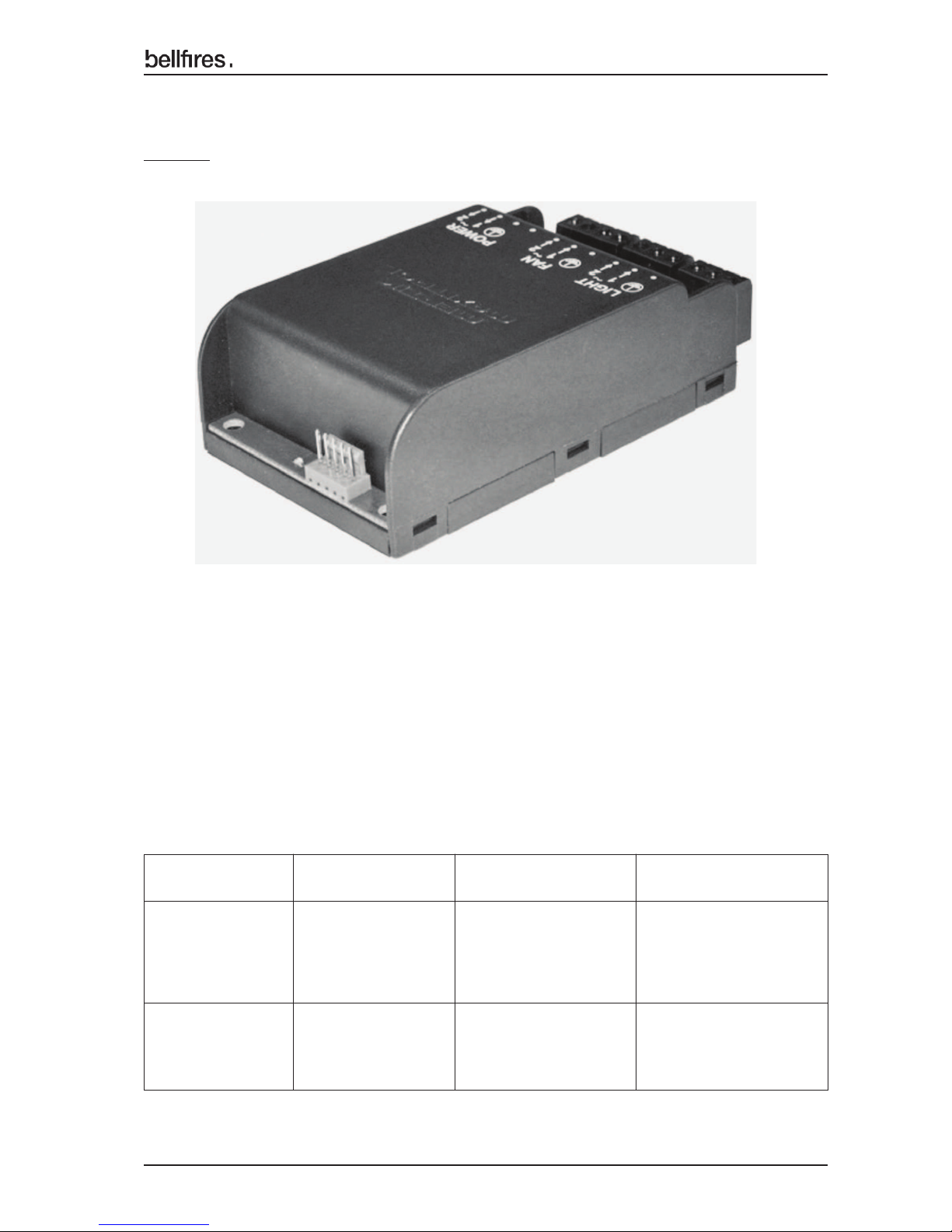
Figure 23A: Module (Light)
The appliance is fi tted with a 230V AC connection and may only be connected to an
earthed socket. The appliance has ambient lighting.
SUPPLEMENT TO CHAPTER 1: INSTALLATION INSTRUCTIONS
Page 56:
Appliance Module (light) 230V AC
Receiver 6V DC (via the Important: Do
Remote control 5-pole cable not place batteries
of the Module in the receiver!
(Light))
Hand
transmitter 1x 9V Block battery
Remote control
Electrical connections and batteries:
Page 8
8
English
Installation instructions
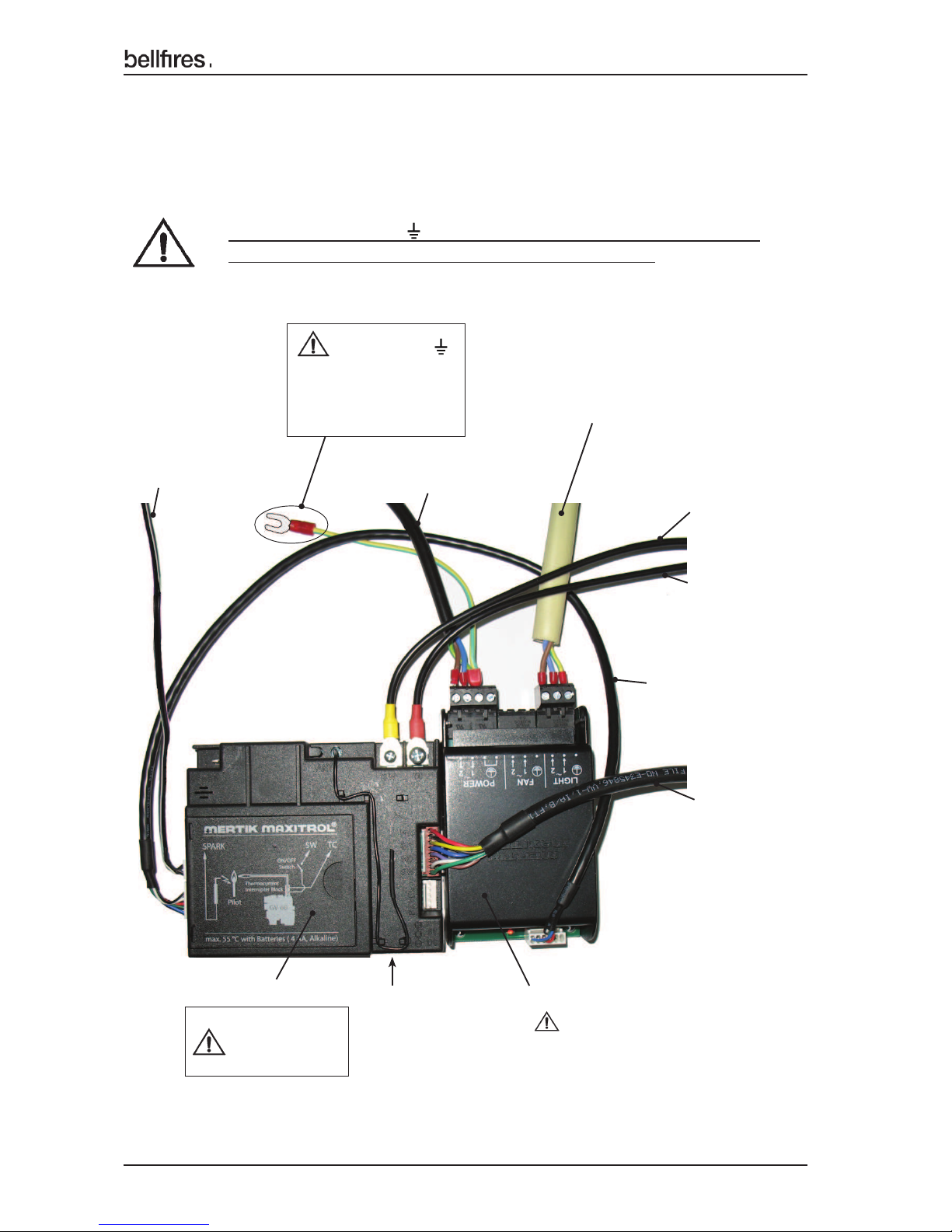
Figure 23B: Electrical connections Receiver and Module(Light)
Upon delivery of the appliance, the electrical connections of the gas regulator block and
the receiver are already assembled.
The Module(Light) is separately delivered with the appliance. This component is to be
electrically connected during the installation according to the following Figure 23B and 23C.
Attach the earth cable (yellow/green) to a metal part on the inside
of the operating unit, with the help of the existing screw.
3 wire cable 230 VAC
Module(light) → Ambient Lamps (2x 25W)
RESET - button
Thermocouple
voltage/current
OUT - connection
(yellow)
Thermocouple
voltage/current
IN - connection
(red)
5 wire cable 6 VDC
MODULE receiver →
Module(light)
8 wire cable
6 VDC
Receiver →
Gas regulator
block
Module(light)
230 VAC
Receiver
2 wire cable 6 VDC
AUX receiver →
Gas valve
“rear burner”
230 VAC Appliance power
cable 3 wire cable
Earth cable
(yellow / green)
Attach this cable to a
metal part of the
operating unit.
Do not place
batteries in the
receiver!
Page 9
9
English
Installation instructions
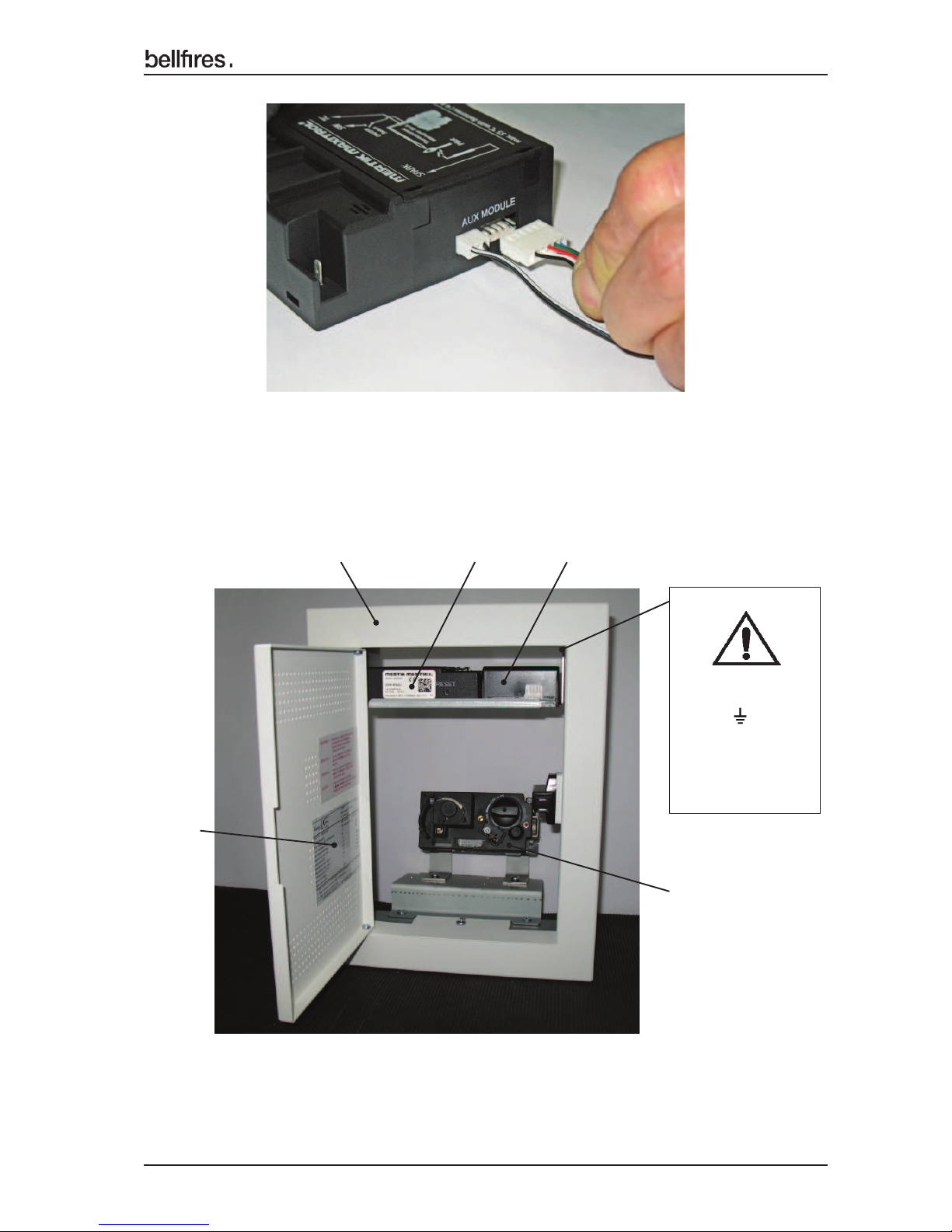
Figure 23C: Connecting 5 wire cable 6VDC on MODULE connection of
the receiver
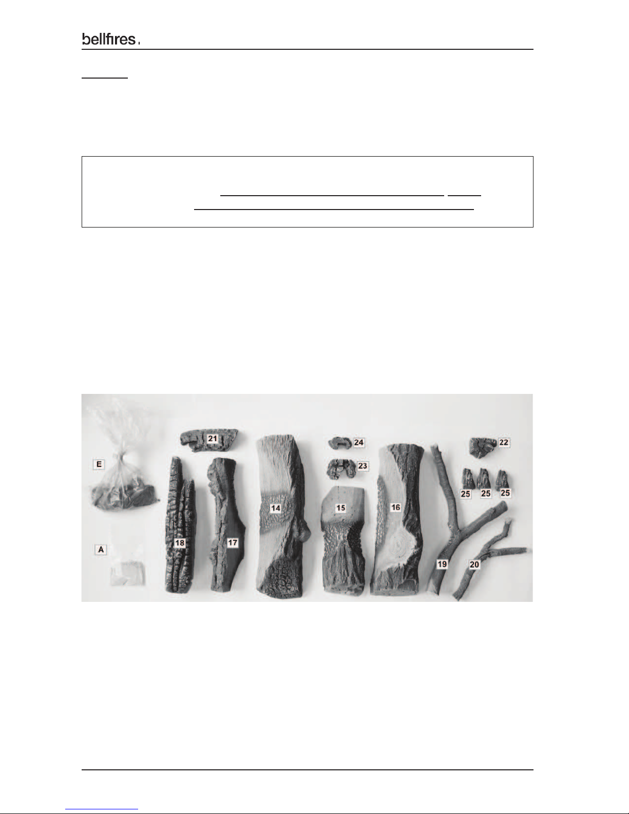
Figure 23D: Built-in operating unit
Position Receiver, Module(Light) and Gas regulator block
(Components are in the picture not yet electrically connected!)
Built-in
operating unit
Receiver
Module(Light)
Rating
plate
Gas regulator block
Attach the Earth
cable (yellow /
green) to a
metal part on the
inside of the
operating unit.
Page 10
10
English
Installation instructions
Page 64:
1.7.6 Placing the ceramic log set, ‘fi re glass’, embers and decorative ash.
For appliance fi tted with the "Premium Fire" (PF) double burner:
The construction of the ceramic log set, "fi re glass", embers and decorative ash
for an appliance with a "Premium Fire (PF) NATURAL GAS double burner is
the same as for a Premium Fire (PF) PROPANE/BUTANE double burner.
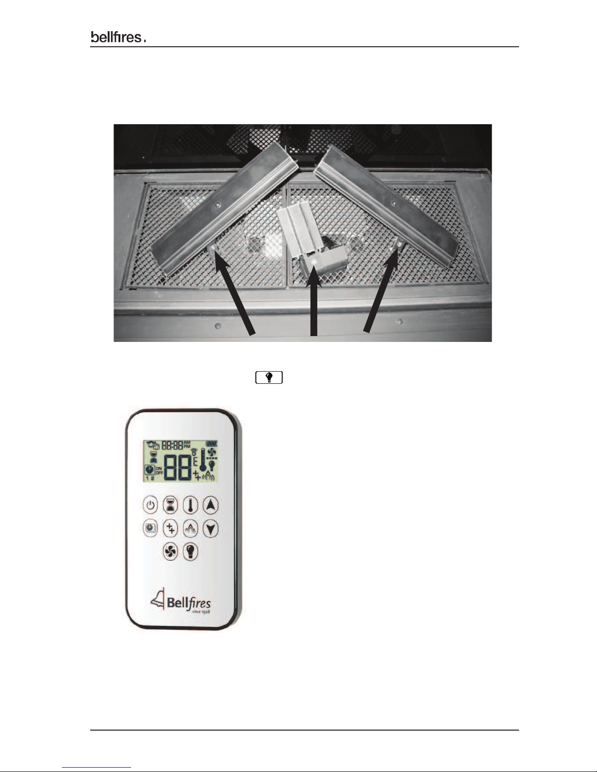
The appliance is supplied with
• Ceramic log set ; See Log Nos. 14 to 25 below.
• "Fire glass Black"
• "Fire glass Dark Amber"
• Embers
• Decorative ash
°
Ceramic log set; Logs nos. 14 to 25
°
Embers; E
°
Decorative ash; A
Page 11

11
English
Installation instructions
• "Fire glass Black
• "Fire glass Dark Amber"
• Embers; E
Page 12

12
English
Installation instructions
• Decorative ash; A
Important : • Place the log set, ‘fi re glass’, embers and decorative ash,
carefully on and around the main burners, as indicated by the
specifi cations mentioned in this chapter.
• Do not place "fi re glass", embers or decorative ash on or
against the pilot light burner.
• To prevent this, the pilot light is fi tted with a pilot light cap.
Never remove this cap!
• Ensure that the pilot light is always able to burn
freely over the main burner.
Proper ignition of the main burner will only be guaranteed if this
is the case. Not adhering to these stipulations can give rise to
dangerous situations.
• Ensure that the pilot light is always easily visible.
• The burner bed (with '"fi re glass", embers and decorative ash)
and the logs construction may not be changed.
• Only use materials supplied! This has been approved and the
quantity is defi ned per appliance.
• Replacement parts are available through your dealer.
• Placement may only be carried out by an authorised
person.
Remove the glass from the appliance, in accordance with the specifi cations in
Chapter 4; DISASSEMBLY / ASSEMBLY OF THE GLASS.
See (basic) installation instructions.
Page 13
13
English
Installation instructions
If necessary repair the ambient lighting.
See Chapter 4A: DISASSEMBLY AND ASSEMBLY OF THE BURNERS AND
MESH GRATES - REPLACING THE AMBIENT LIGHTING.
Only use original ambient lights.
Check the operation of the ambient lighting/dimmer with the remote control.
See operating instructions; Operation light / dimmer
1.7.6.1 Ceramic log set + ‘fi re glass’ + embers + decorative ash
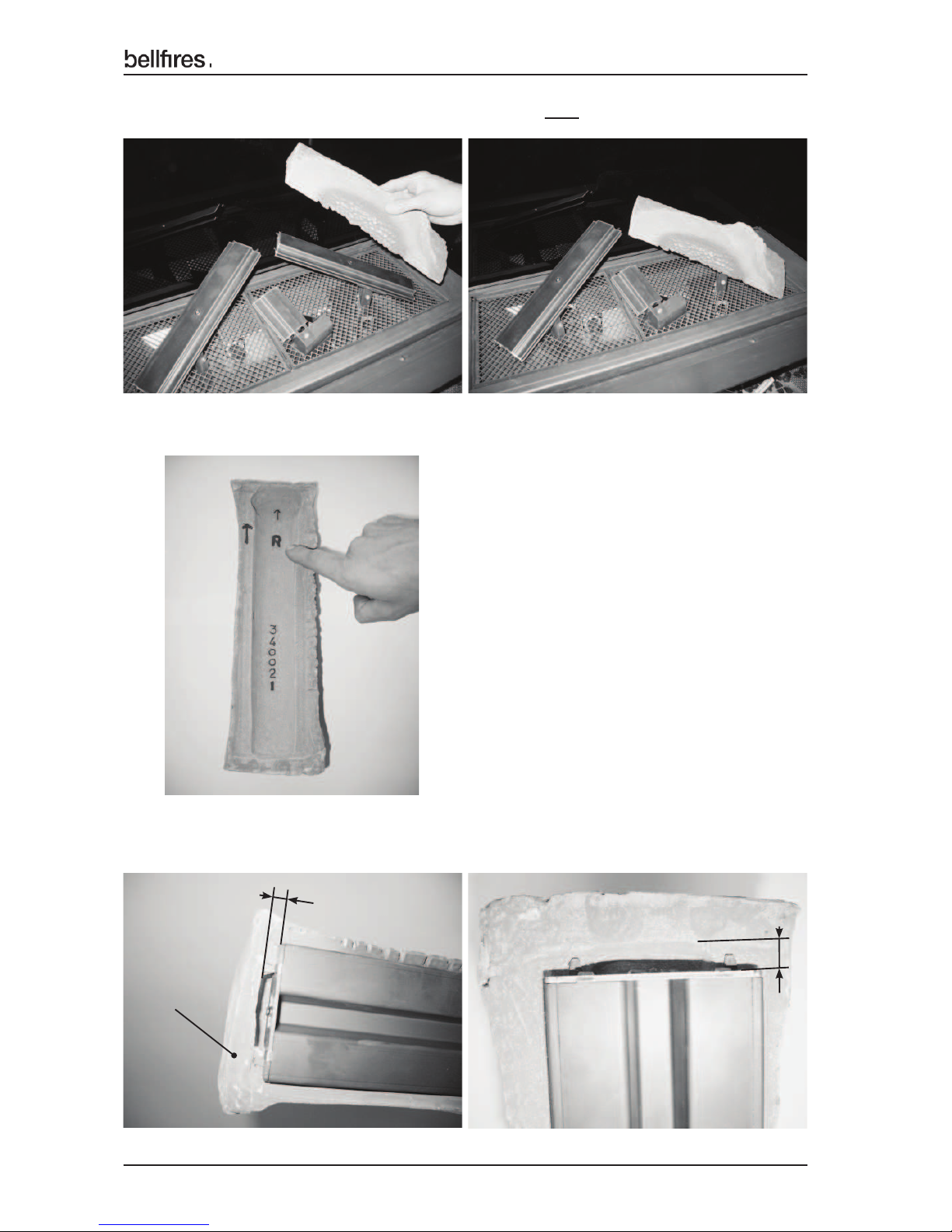
1 IMPORTANT: Check the presence of the three burner fi xing bolts.
See photo.
Page 14
14
English
Installation instructions
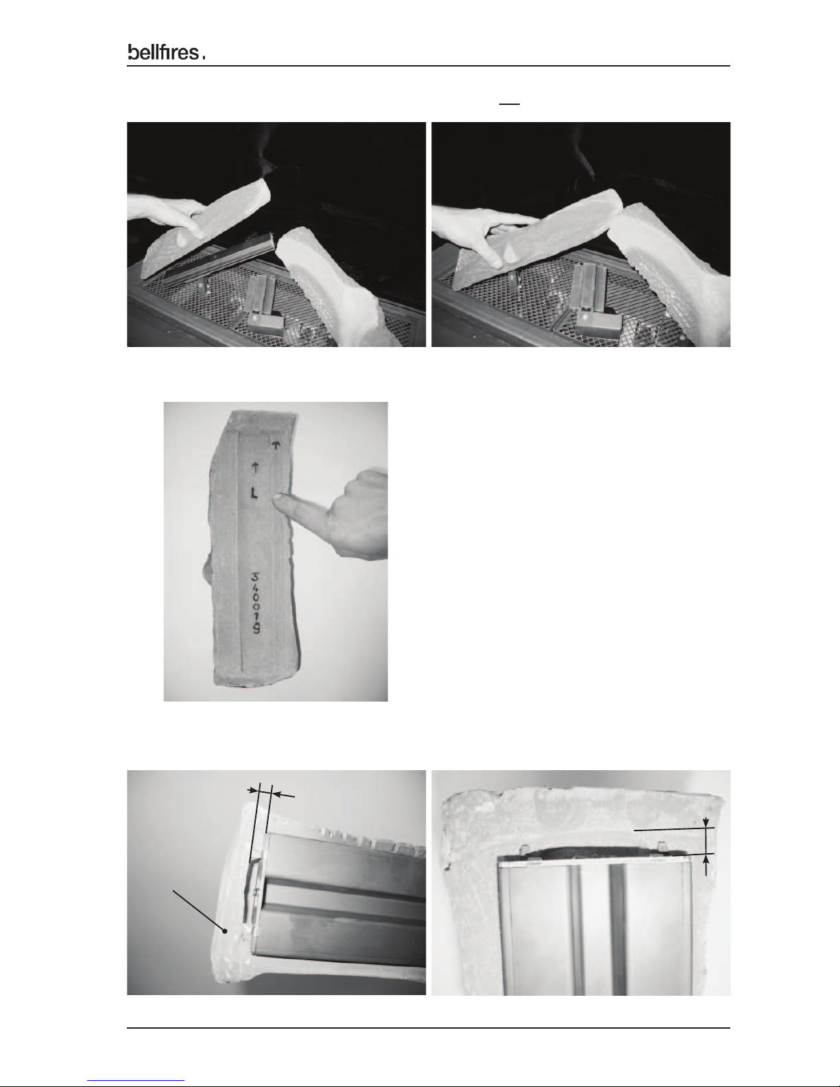
2 Place burner log No. 16 carefully on the burner - right.
Check fi rst if the "Arrow", on the underside of the log, is pointing up.
Check that the underside of the log has free space on both end faces of ± 5 mm
with respect to the metal burner.
Burner log No. 16 =
Art. no. 340021 (legible on
the underside of the log)
Underside
of log
Underside
± 5 mm
Burner
± 5 mm
Underside
of log
Underside
Burner
Page 15
15
English
Installation instructions
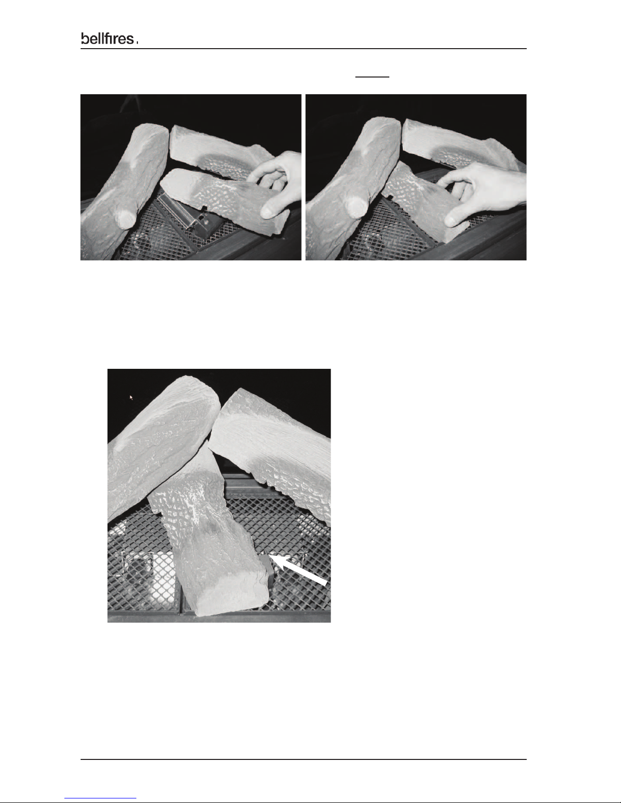
3 Place burner log No. 14 carefully on the burner - left.
Check fi rst if the "Arrow", on the underside of the log, is pointing up.
Burner log No. 14
Art. no. 340019 (legible on
the underside of the log)
Check that the underside of the log has free space on both end faces of ± 5 mm
with respect to the metal burner.
Underside
of log
Underside
± 5 mm
Burner
± 5 mm
Underside
of log
Underside
Burner
Page 16
16
English
Installation instructions
4 Place burner log No. 15 carefully on the burner - middle (with the pilot light).
Burner log No. 15 = Art. no. 340020 (legible on the underside of the log)
Check that the pilot light remains visible.
Page 17
17
English
Installation instructions
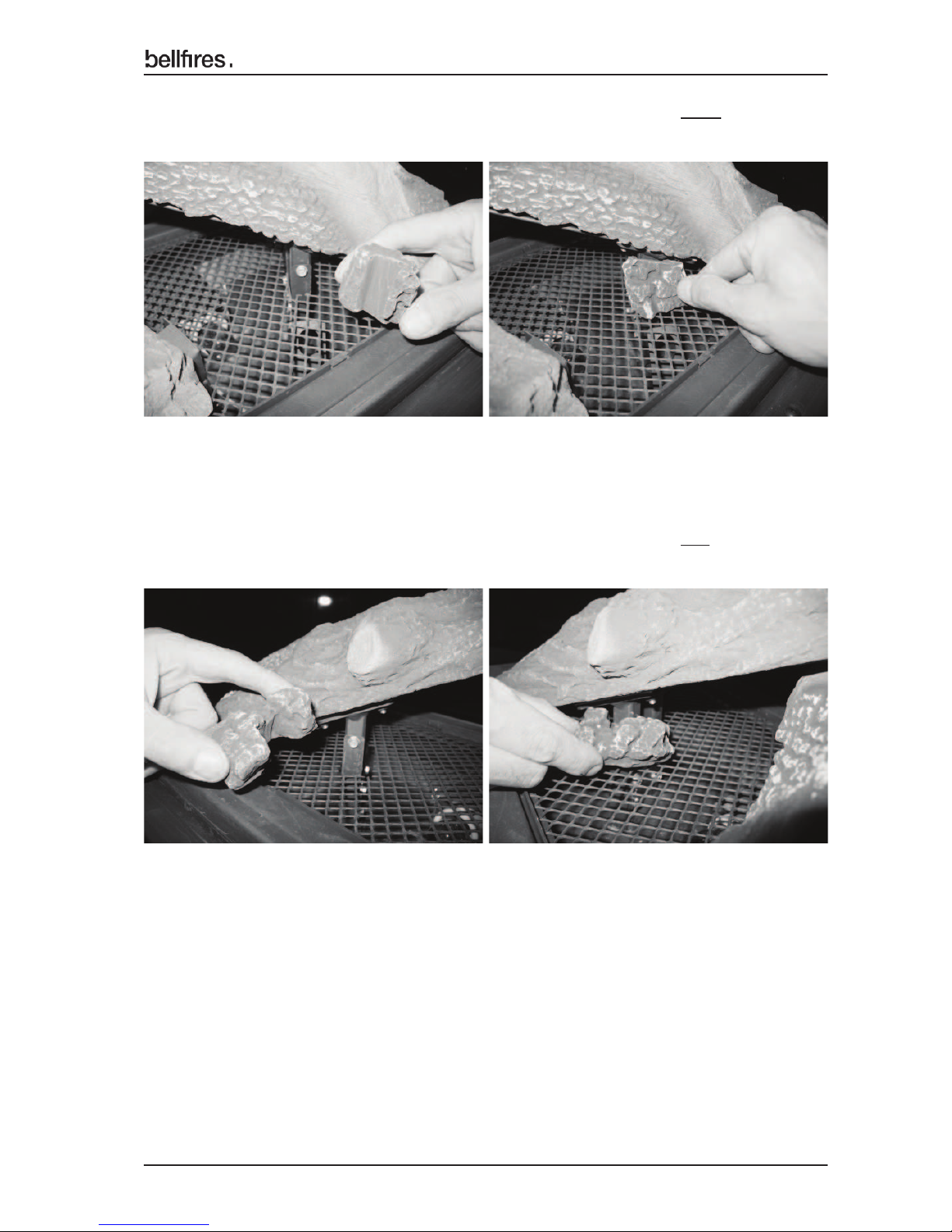
5 Place the charcoal part No. 23 (= 1x Art. no. 340028) under the Right burner,
around the venturi.
6 Place the charcoal part No. 24 (= 1x Art. no. 340029) under the Left burner,
around the venturi.
Page 18
18
English
Installation instructions
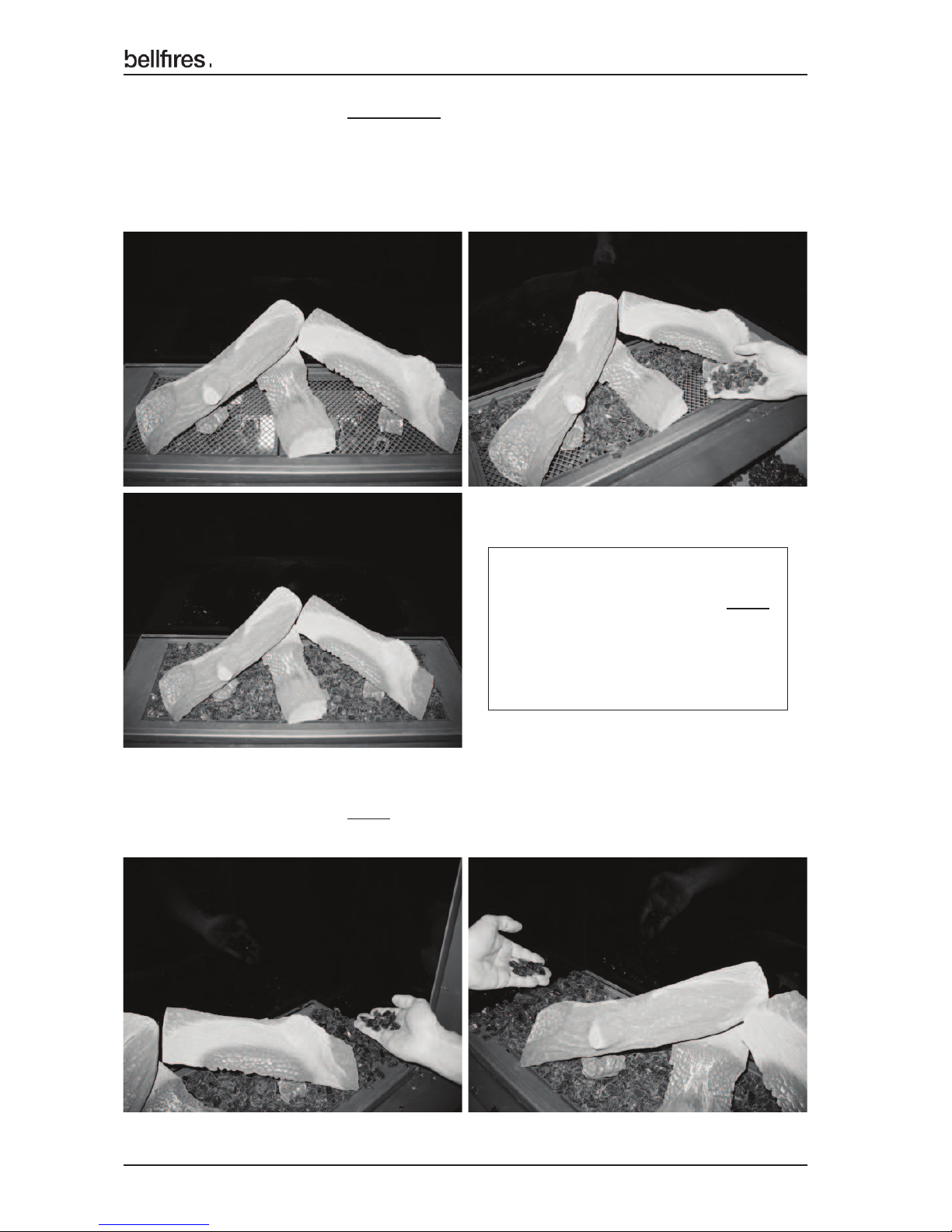
8 Sprinkle the ‘Fire glass Black’ evenly on the grate, left and right of the
mesh grate.
7 Sprinkle the ‘Fire glass Dark Amber’ evenly on the mesh grate, around the
burners.
Note: Put no "fi re glass" on or against the pilot light burner!
Note: Put no ‘fi re glass’ under burner logs No. 14, 15 and 16, where these
are supported by the mesh grate.
Note!
Do not sprinkle "Fire glass Black"
on the mesh grate, around
the burners.
‘Fire glass Black’ blocks the
light too much.
Page 19
19
English
Installation instructions
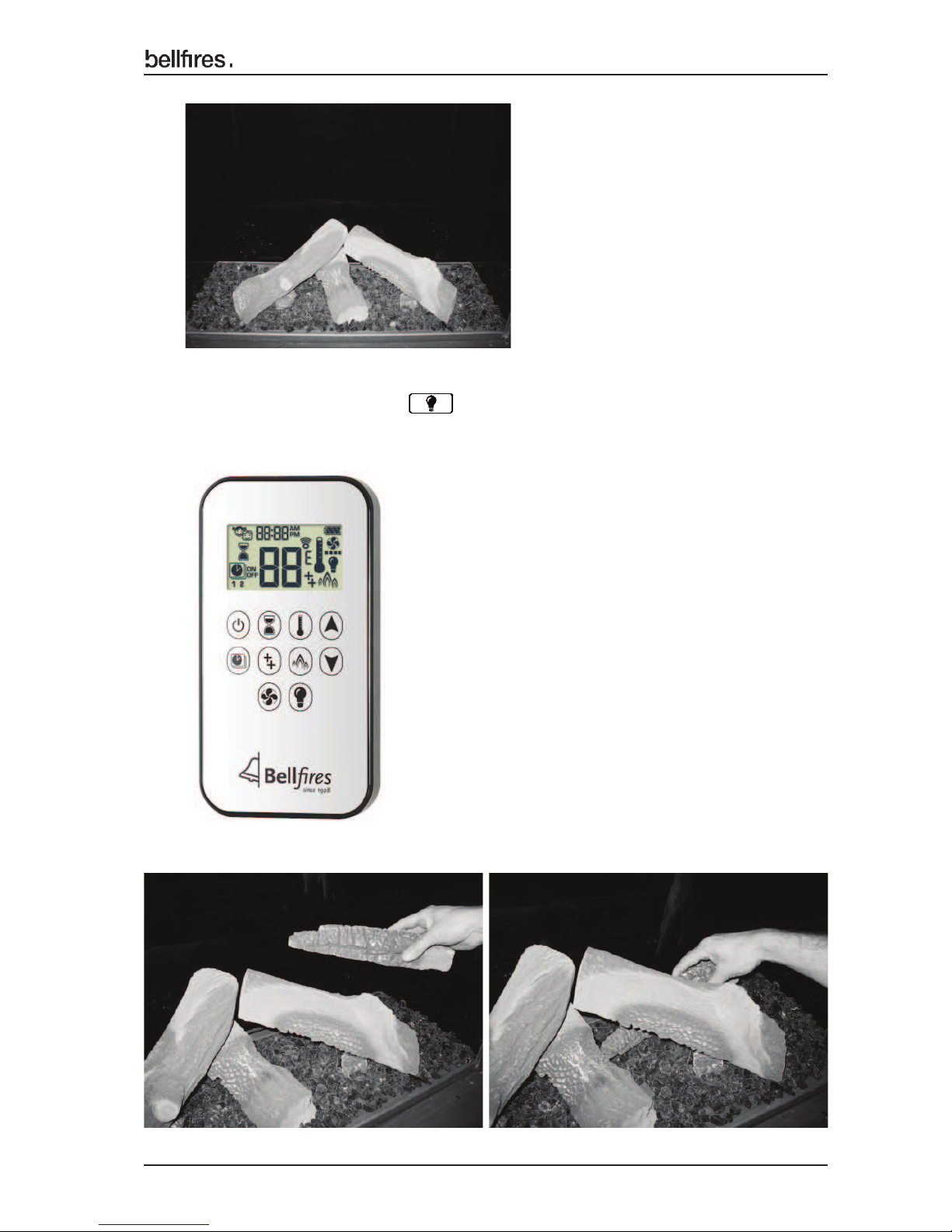
9 Set the light intensity of the ambient lighting/dimmer to max. on the remote control.
See operating instructions; Operation light / dimmer
Check that the "fi re glass" is distributed evenly and that the light intensity is the
same everywhere. Adjust the distribution of the "fi re glass" if necessary.
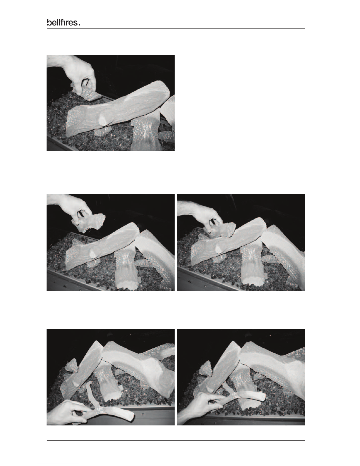
10 Place log No. 18 (= 1x Art. no. 340023).
Page 20
20
English
Installation instructions
11 Place charcoal part No. 21 (= 1x Art. no. 340026).
12 Place log No. 17 (= 1x Art. no. 340022).
13 Place branch No. 19 (= 1x Art. no. 340024).
Page 21
21
English
Installation instructions
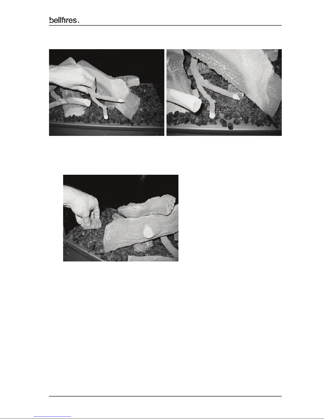
14 Place branch No. 20 (= 1x Art. no. 340025).
15 Place charcoal part No. 22 (= 1x Art. no. 340027).
Page 22
22
English
Installation instructions
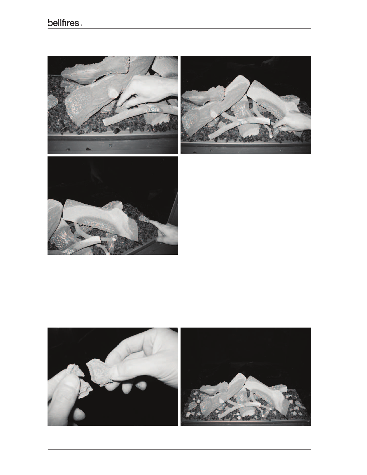
16 Place 3x charcoal parts No. 25 (= 3x Art. no. 340030).
17 Break the embers supplied in half and distribute the parts along the
side on the grate (around the mesh grate).
Note: Do not place any embers on the mesh grate. Embers will block the light!
Note: Put no embers on or against the pilot light burner!
Page 23
23
English
Installation instructions
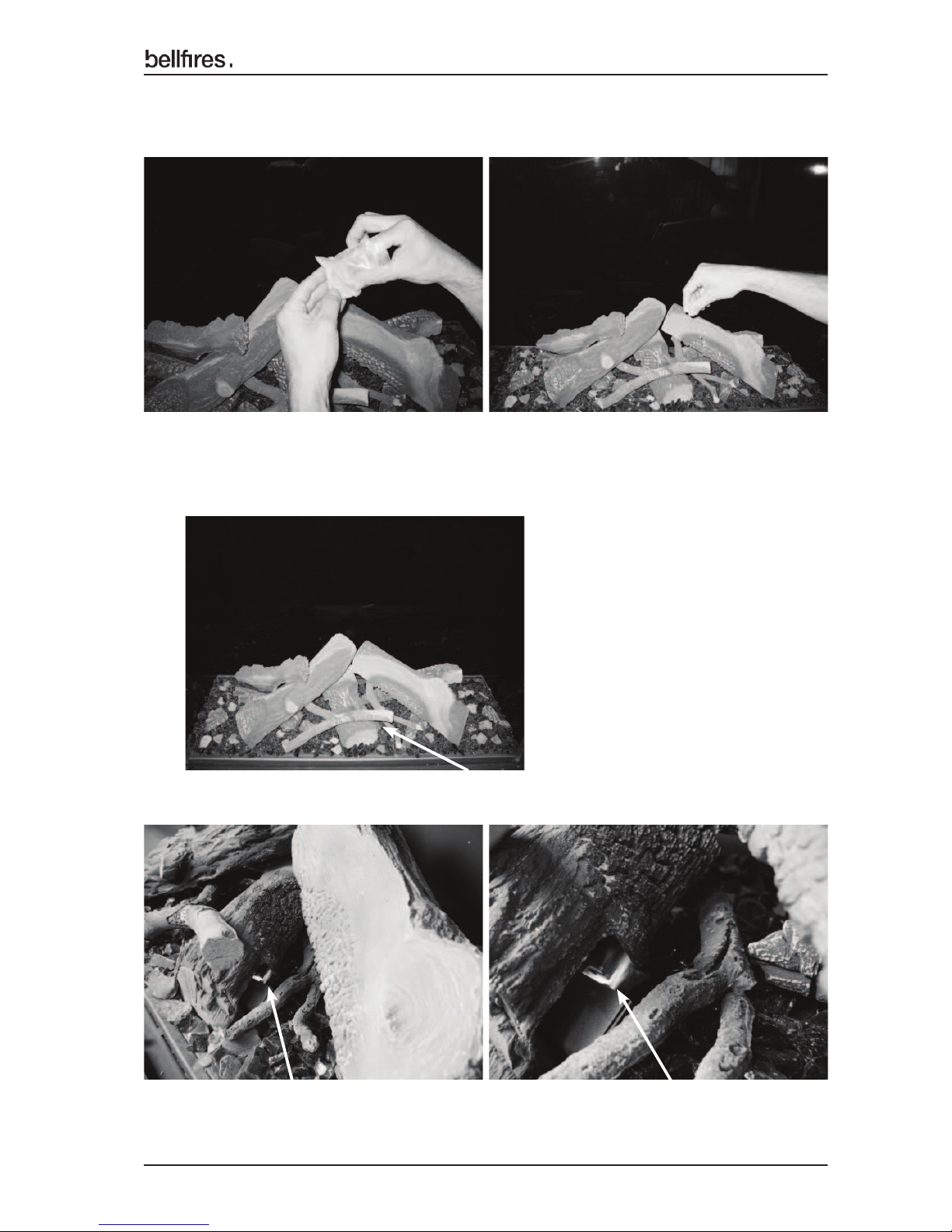
19 Check that the pilot light burner is easily visible from the right hand side of the log
set.
18 Decorative ash: Carefully distribute a small amount of decorative ash over the
entire bottom.
Pilot light position
Pilot light Pilot light
Page 24
24
English
Installation instructions
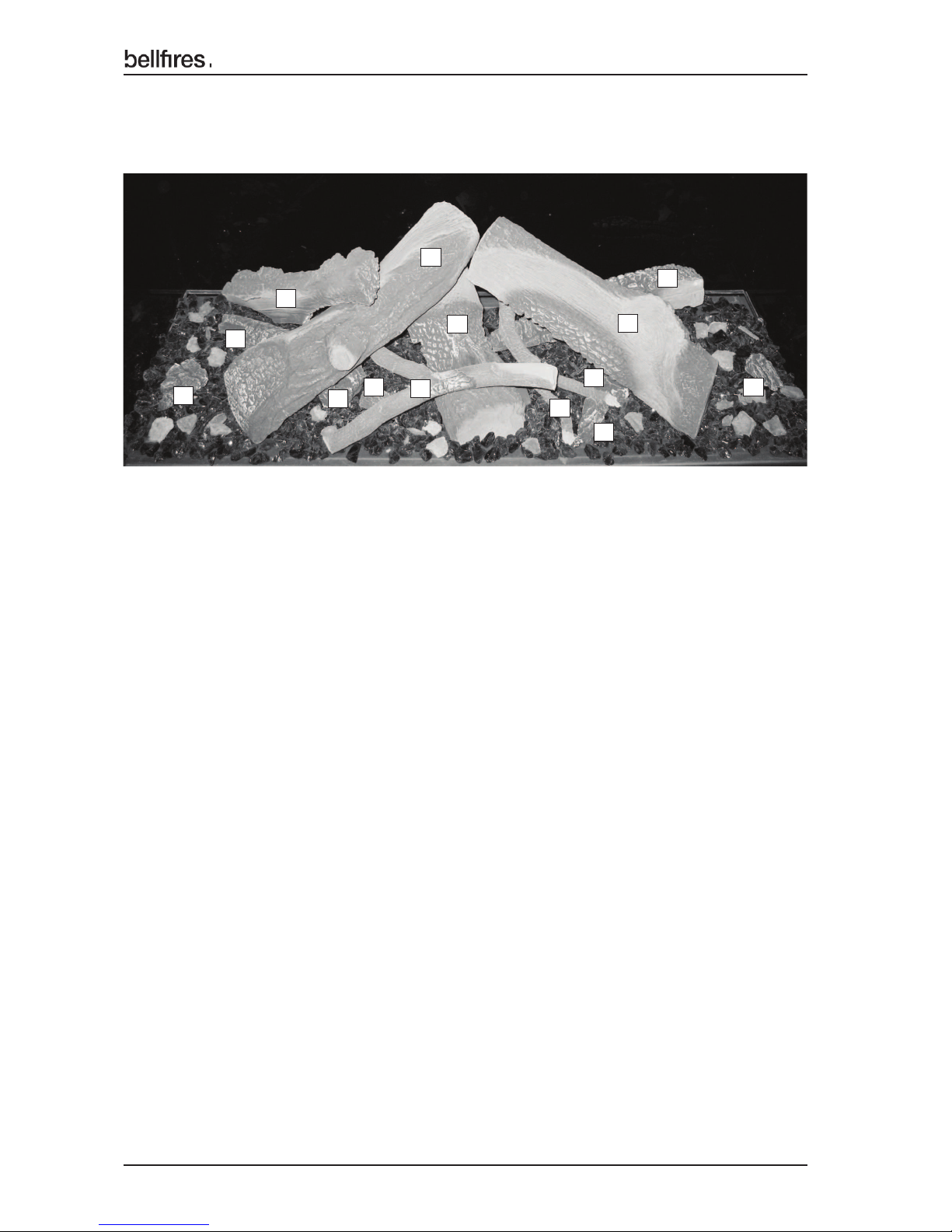
Figure 24: Log set
Set-up of Natural gas and propane/butane burner - "Premium Fire"
IMPORTANT:
• Do not put any "fi re glass" or embers in front of the pilot light burner
• Do not sprinkle decorative ash on the pilot light burner
• Keep the burner orifi ces free
• Check that the pilot light burns properly
• The pilot light must be able to burn freely over the burner
Proper ignition of the main burner will only be guaranteed if this is the case!
When the ceramic logs, "fi re glass" and embers have been placed, the glass can be assembled on the appliance once more in accordance with the specifi cations in Chapter 4:
DISASSEMBLY / ASSEMBLY OF THE GLASS
20 The ceramic log set construction, "fi re glass", embers and decorative ash is
completed.
20
25
25
25
24
19
15
16
18
23
14
17
21
22
Page 25
25
English
Installation instructions
SUPPLEMENT TO CHAPTER 4: DISASSEMBLY / ASSEMBLY OF THE GLASS.
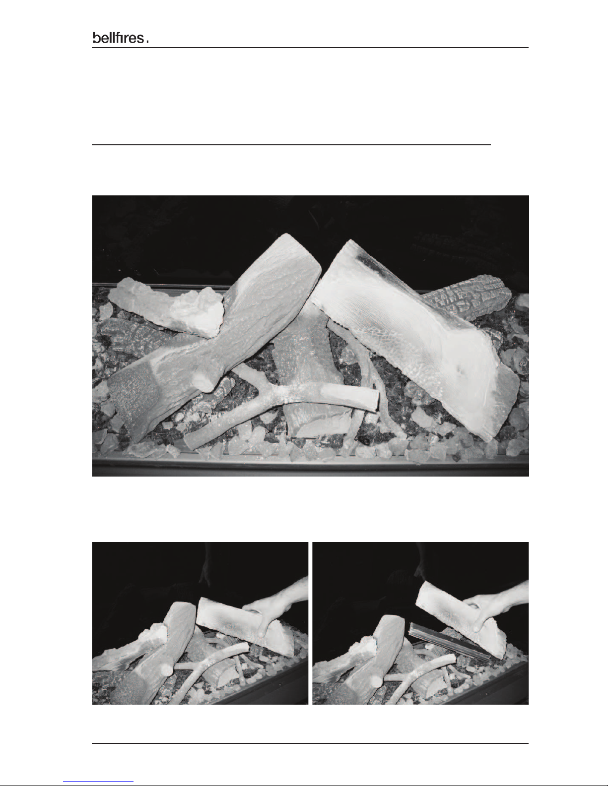
4A DISASSEMBLY AND ASSEMBLY OF THE BURNERS AND MESH GRATES
REPLACING THE AMBIENT LIGHTS
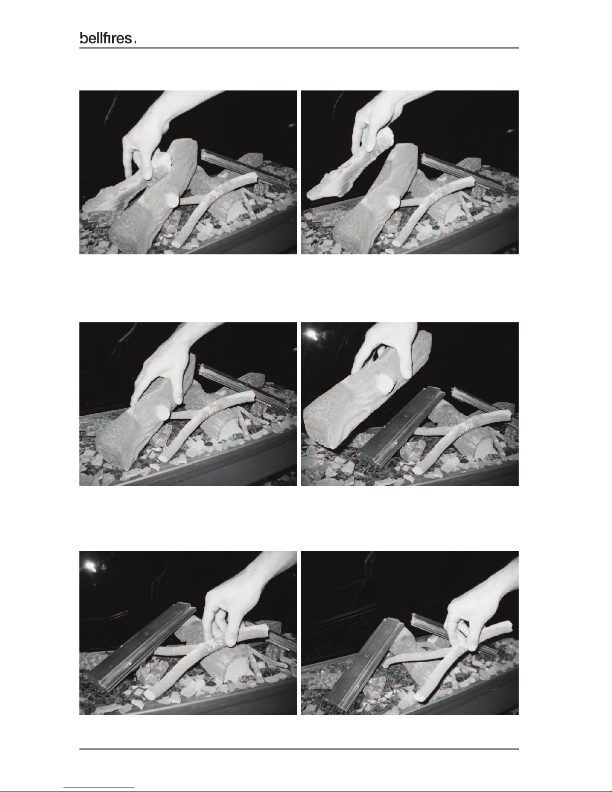
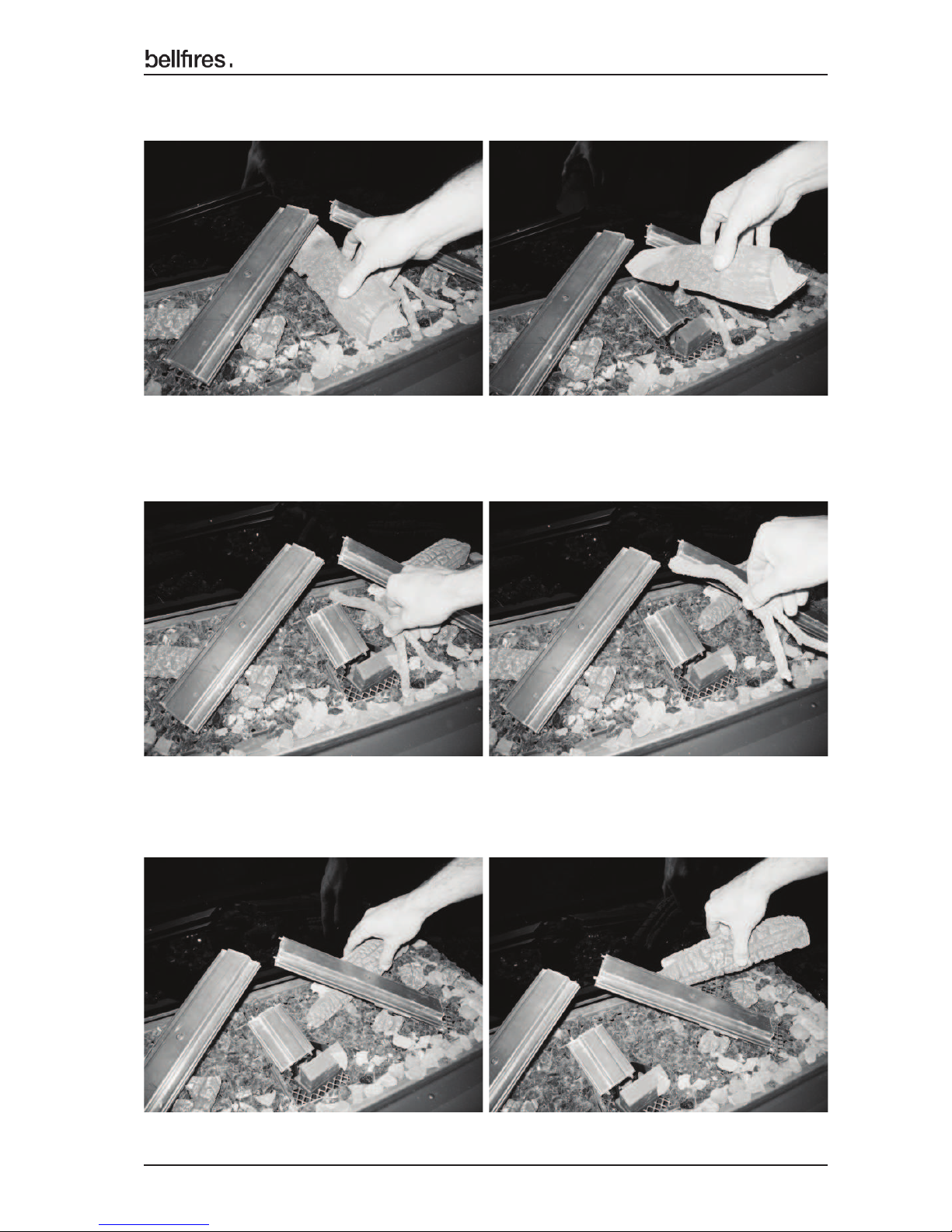
Carefully remove the log set, burners and mesh grates in the following order:
1. Complete log set ‘Premium Fire’
2. Burner log No. 16
Page 26
26
English
Installation instructions
3. Log No. 17
4. Burner log No. 14
5. Branch No. 19
Page 27
27
English
Installation instructions
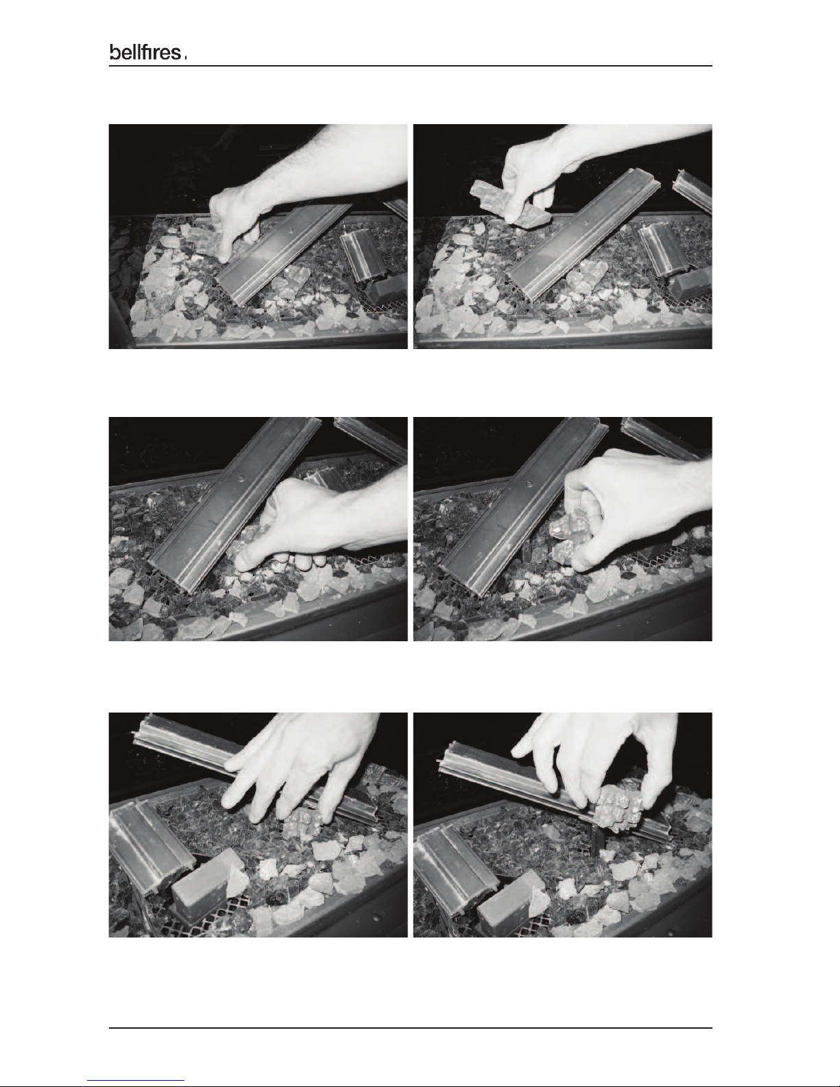
6. Burner log No. 15
7. Branch No. 20
8. Log No. 18
Page 28
28
English
Installation instructions
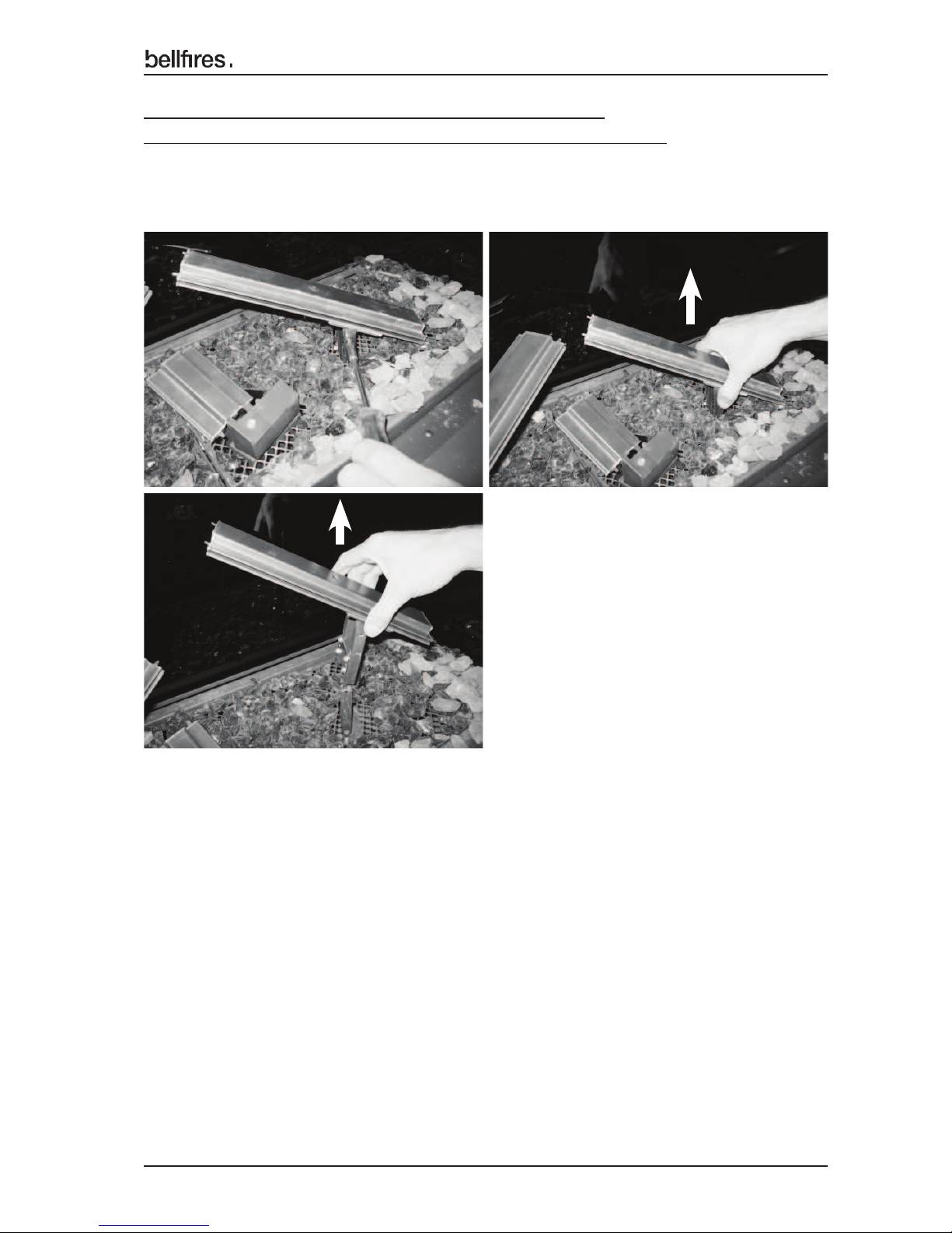
9. Log No. 21
10. Charcoal part No. 24
11. Charcoal part No. 23
12. Charcoal part No. 25 (3x)
Page 29
29
English
Installation instructions
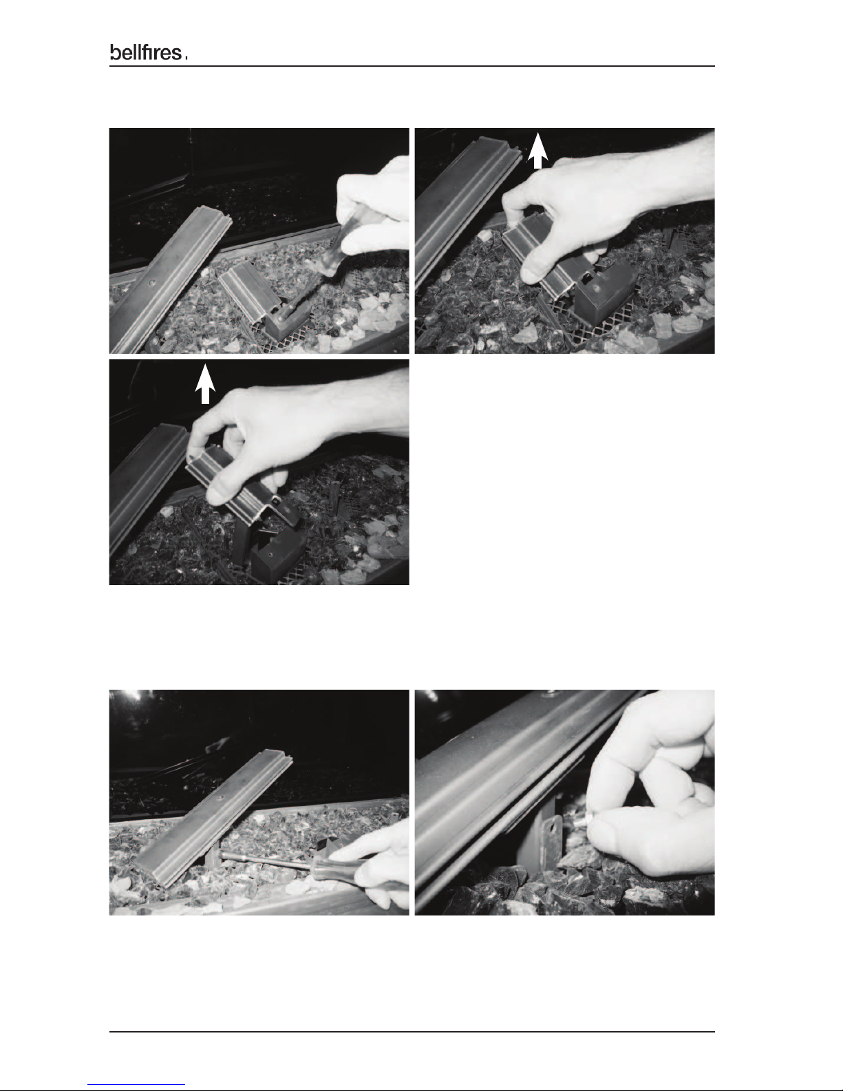
The three burners are all fi xed with just one hexagonal bolt.
When unscrewing the burner fi xing bolts, use socket spanner no. 7.
13. Disassemble and remove the burner - right.
Page 30
30
English
Installation instructions
14. Disassemble and remove the burner - middle.
15. Disassemble and remove the burner - left.
Page 31
31
English
Installation instructions
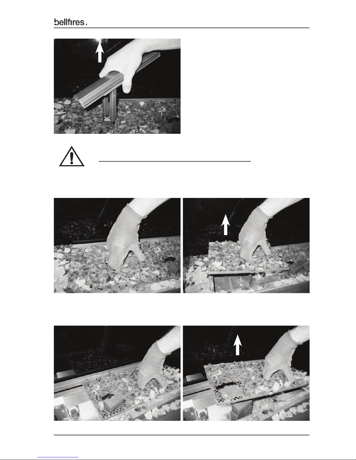
Use working gloves when removing the mesh grates.
16. Carefully remove the mesh grate - left.
17. Carefully remove the mesh grate - right.
Page 32
32
English
Installation instructions
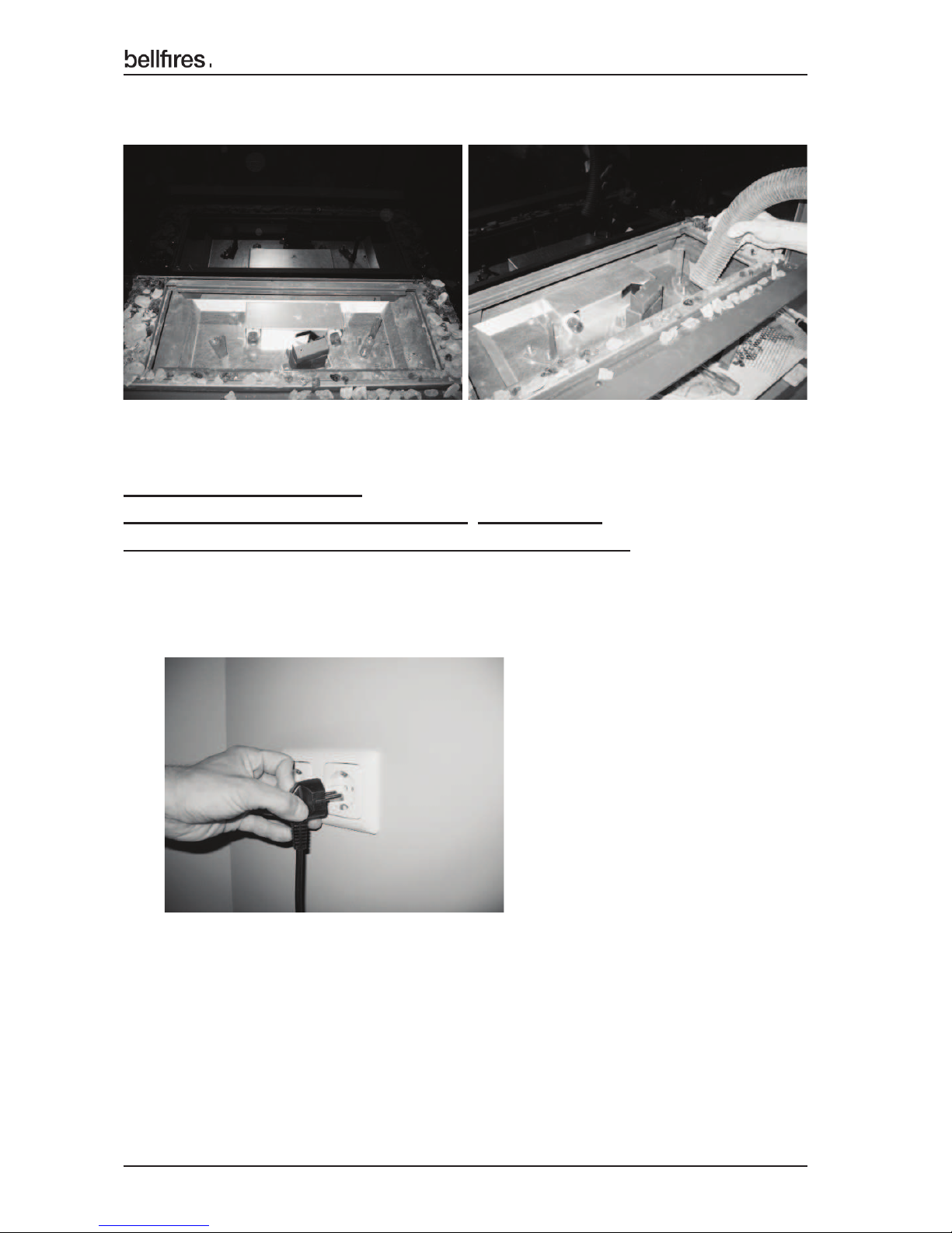
18. Clean the light compartment and gas injectors with a vacuum cleaner.
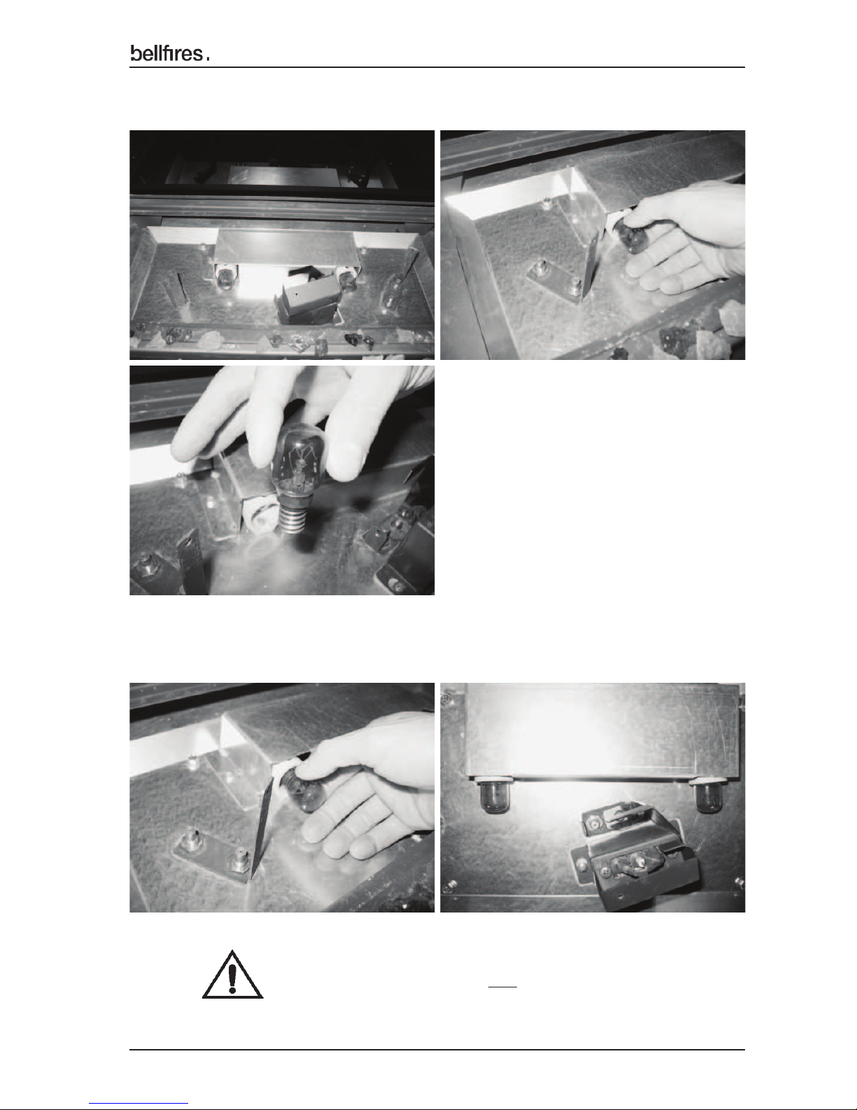
Replacing the ambient lights.
Only use original Bellfi res ambient lamps: Art. no. 333748:
Ambient lamp; 230-240V - 25W - E14 - 300"C. - Colour: Amber
19. Remove the plug of the appliance from the socket.
Page 33
33
English
Installation instructions
21. Carefully screw the new lamp into the ! tting.
20. Carefully unscrew the defective lamp from the ! tting.
Screw the ambient lamps fully into the fi tting"
Page 34
34
English
Installation instructions
22. Replace the plug of the appliance into the socket.
23. Check the operation of the ambient lighting/dimmer with the remote control.
See operating instructions; Operation light / dimmer
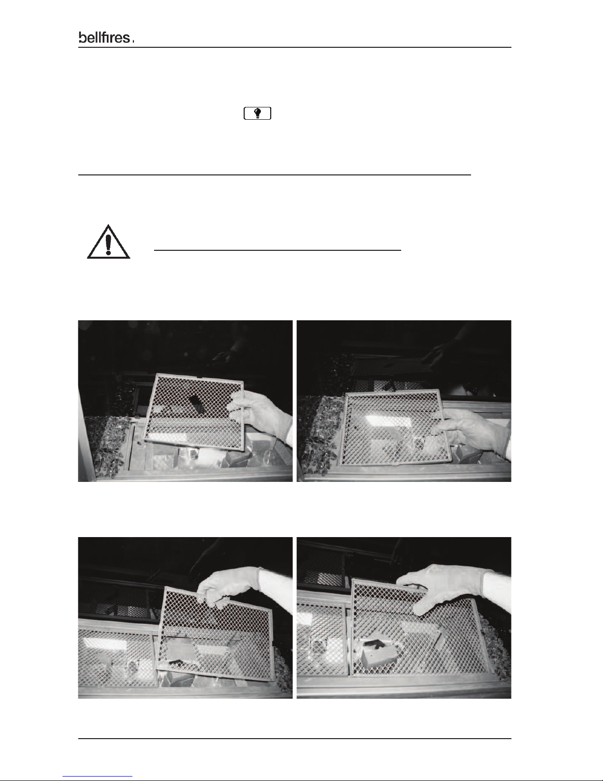
Use working gloves when placing the mesh grates.
Carefully place the mesh grates, burners and log set in the following order:
24. Carefully place the mesh grate - left.
25. Carefully place the mesh grate - right.
Page 35
35
English
Installation instructions
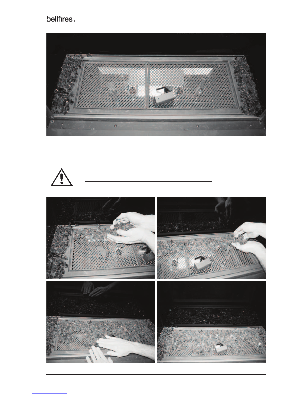
26. Sprinkle the "Fire glass Dark Amber" on the rear of the mesh grates.
Do not let any "fi re glass" fall in the grate apertures.
Page 36
36
English
Installation instructions
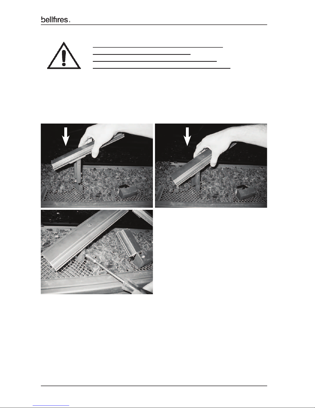
Fix each burner with the hexagon bolt supplied.
Use socket spanner no. 7 to do this.
Not mounting these ! xing bolts can give rise
to a dangerous situation. Prevent this at all costs!
27. Place and assemble the burner - left.
Press the burner down fi rmly, and mount the fi xing bolt.
Page 37
37
English
Installation instructions
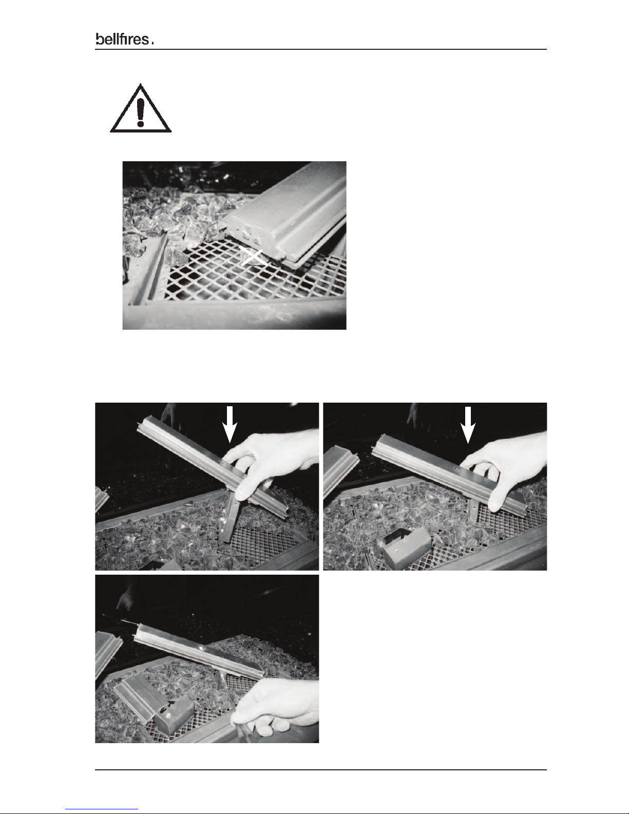
28. Place and assemble the burner - right.
Press the burner down ! rmly, and mount the ! xing bolt.
Make sure that no “!re glass” parts are under the
lowest point of the burner!
The lowest point of the burner must be able to float
above the mesh grate.
Page 38
38
English
Installation instructions
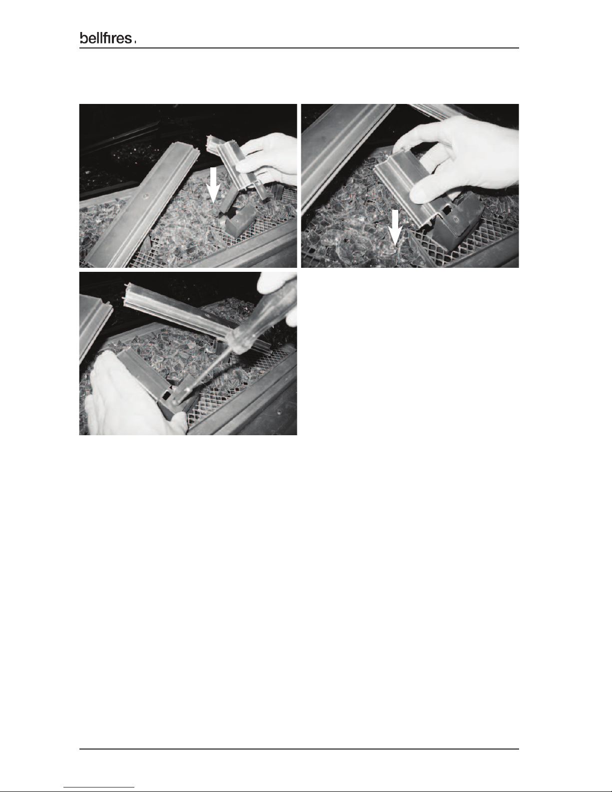
30. Place the Ceramic log set, ‘! re glass’, embers and decorative ash,
as indicated in chapter 1.7.6.1
29. Place and assemble the burner - middle.
Press the burner down ! rmly, and mount the ! xing bolt.
Page 39
39
English
Installation instructions
SUPPLEMENT CH. 7: TECHNICAL DETAILS AND REGULATIONS
National installation regulations:
• Gas safety installation and use regulations 1998 plus all relevant
safety and building regulations concerning ! re installation
• Document J: Combustion appliances and fuel storage systems
Model : DERBY LARGE 3 PF (PREMIUM FIRE)
DERBY SMALL 3 PF (PREMIUM FIRE)
TOPSHAM LARGE 3 PF (PREMIUM FIRE)
YORK LARGE 3 PF (PREMIUM FIRE)
YORK SMALL 3 PF (PREMIUM FIRE)
VIEW BELL DERBY 3 PF (PREMIUM FIRE)
VIEW BELL SMALL 3 PF (PREMIUM FIRE)
VIEW BELL TOPSHAM 3 PF (PREMIUM FIRE)
VIEW BELL YORK 3 PF (PREMIUM FIRE)
CORNER BELL DERBY 3 L/R PF (PREMIUM FIRE)
CORNER BELL SMALL 3 L/R PF (PREMIUM FIRE)
CORNER BELL TOPSHAM 3 L/R PF (PREMIUM FIRE)
CORNER BELL YORK 3 L/R PF (PREMIUM FIRE)
Gas : NATURAL GAS : BUTANE / PROPANE
Country :
GB; G
reat Britain
/IE;
Ireland :
GB; G
reat Britain
/IE;
Ireland
Product identifi cation no. : 0063CM3684 : 0063CM3684
Appliance type acc. to CE standard : C11 / C31 / C91 : C11 / C31 / C91
Appliance category : I2H natural gas G20 : I
3B/P
butane/propane G30/G31
Nominal heat input : 12.1 kW : Butane (G30) : 11.2 kW
(Gross calorifi c value) Propane (G31) :
9.6 kW
Nominal heat output : 9.3 kW : 7.4 - 8.6 kW
Effi ciency class : 1 (85%) : 1 (85%)
NOx class : 5 : 5
Gas rate (max.) : 1.15 m
3
s
/hr. : Butane (G30) : 850 gr/hr.
Propane (G31) : 720 gr/hr.
Supply pressure : 20.0 mbar : Butane (G30) : 37.0 mbar
Propane (G31) : 37.0 mbar
Burner pressure (max.) Hot : 14.1 mbar(*) : 29.0 mbar(*)
Burner pressure (max.) Cold : 13.4 mbar(**) : 29.0 mbar(**)
Burner pressure (min.) : 4.0 mbar(***) : 7.0 mbar(***)
Primary air inlet burner L : LR: Ø6.0 mm : LR: Ø14 x 8 mm
Left-Rear and Left-Front LF: Ø3.5 mm LF: Ø14 x 8 mm
Primary air inlet burner M : MF: Ø6.0 mm : MF: Ø15 x 8 mm +
Middle-Front
2x Ø3.5 mm
Primary air inlet burner R : RR: Ø6.0 mm : RR: Ø14 x 8 mm
Right-Rear and Right-Front RF: Ø3.5 mm RF: Ø14 x 8 mm
Page 40
40
English
Installation instructions
Model : DERBY LARGE 3 PF (PREMIUM FIRE)
DERBY SMALL 3 PF (PREMIUM FIRE)
TOPSHAM LARGE 3 PF (PREMIUM FIRE)
YORK LARGE 3 PF (PREMIUM FIRE)
YORK SMALL 3 PF (PREMIUM FIRE)
VIEW BELL DERBY 3 PF (PREMIUM FIRE)
VIEW BELL SMALL 3 PF (PREMIUM FIRE)
VIEW BELL TOPSHAM 3 PF (PREMIUM FIRE)
VIEW BELL YORK 3 PF (PREMIUM FIRE)
CORNER BELL DERBY 3 L/R PF (PREMIUM FIRE)
CORNER BELL SMALL 3 L/R PF (PREMIUM FIRE)
CORNER BELL TOPSHAM 3 L/R PF (PREMIUM FIRE)
CORNER BELL YORK 3 L/R PF (PREMIUM FIRE)
Gas : NATURAL GAS : BUTANE / PROPANE
Country :
GB; G
reat Britain
/IE;
Ireland :
GB; G
reat Britain
/IE;
Ireland
Gas regulator block (remote control) : Mertik GV 60 : Mertik GV 60
Main burner : Premium Fire 600 x 240 mm : Premium Fire 600 x 240 mm
Main burner injector L : LR: Ø1.50 mm : LR: Ø0.80 mm
Left-Rear and Left-Front LF: Ø1.20 mm LF: Ø0.75 mm
Main burner injector M : MF: Ø1.30 mm : MF: Ø0.75 mm
Middle-Front
Main burner injector R : RR: Ø1.50 mm : RR: Ø0.80 mm
Right-Rear and Right-Front RF: Ø1.20 mm RF: Ø0.75 mm
Pilot light burner : SIT 0.145.019 : SIT 0.145.019
Pilot light burner injector : no. 36 (SIT 0.977.091) : no. 23 (SIT 0.977.150)
Gas connection : 3/8” G / Ø12 mm : 3/8” G / Ø12 mm
Concentric fl ue system connection : Ø100 mm - Ø150 mm or : Ø100 mm - Ø150 mm or
Ø130 mm - Ø200 mm Ø130 mm - Ø200 mm
Remote control batteries
- Receiver : N/A : N/A
- Hand transmitter : 2x 1.5V AAA : 2x 1.5V AAA
Electrical connection : 230 VAC / 50 Hz : 230 VAC / 50 Hz
Electrical power consumption : 50 W (max.) / IP 20 : 50 W (max.) / IP 20
Weight : See the basic installation instructions
(*) : All burners at maximum setting and appliance at the required temperature.
(**) : All burners at maximum setting and appliance cold.
(***) : All burners at minimum setting.
Flue gas exhaust and combustion air supply:
Roof termination : Concentric fl ue system Ø100 mm-Ø150 mm rigid and/or fl exible.
Wall termination : Concentric fl ue system Ø130 mm-Ø200 mm rigid.
With wall outlet, depending on the fl ue construction; Ø100 mm-Ø150 mm or
Ø130 mm-Ø200 mm.
Heat exchanging surface: Entire front of the appliance.
"Front Burner" = LF + MF + RF
"Rear Burner" = LR + RR
Page 41

41
English
Installation instructions
SUPPLEMENT CH. 8: REPLACEMENT PARTS LIST
No. Article no. Description
Main burner "Premium Fire" 600 x 240 mm
Natural gas G20 / Butane/Propane G30/G31
1 3......... G20: Ø6.0 mm Left-Rear
Ø3.5 mm Left-Front
Ø6.0 mm Middle-Front
Ø6.0 mm Right-Rear
Ø3.5 mm Right-Front
2 3......... G30/G31: Ø14x8 mm Left-Rear
Ø14x8 mm Left-Front
Ø15x8 mm + 2x Ø3.5 mm Middle-Front
Ø14x8 mm Right-Rear
Ø14x8 mm Right-Front
3 301915 Main burner injector Natural gas; Left-Rear: Ø1.50 mm
4 334874 Main burner injector Natural gas; Left-Front: Ø1.20 mm
5 301928 Main burner injector Natural gas; Middle-Front: Ø1.30 mm
6 301915 Main burner injector Natural gas; Right-Rear: Ø1.50 mm
7 334874 Main burner injector Natural gas; Right-Front: Ø1.20 mm
8 340430 Main burner injector Butane/Propane; Left-Rear: Ø0.80 mm
9 340431 Main burner injector Butane/Propane; Left-Front: Ø0.75 mm
10 340431 Main burner injector Butane/Propane; Middle-Front: Ø0.75 mm
11 340430 Main burner injector Butane/Propane; Right-Rear: Ø0.80 mm
12 340431 Main burner injector Butane/Propane; Right-Front: Ø0.75 mm
13
341643 Handheld Transmitter Symax 2 - EU - 10 buttons Bellfi res
14 341644 Receiver Symax 2 - EU
15 333605 Module 230V AC (Light)
16 333912 Fuse T 2.5A 250V Module
17 333606 5-Pole cable Receiver - Module
18 333748 Ambient lighting lamp 230V AC, E14, 25W
19 341645 WIFI-box Symax 2 - Bellfi res
20 341647 WIFI-box cable - L= 1000 mm
21 340469 Log set (14 part) Natural gas / Butane/Propane
incl. embers and decorative ash
22 340089 ‘Fire Glass’ Dark Amber (2.5kg)
23 340091 ‘Fire Glass’ Black (1.0 kg)
24 ........... ‘Fire Glass’ Black (0.5 kg)
Page 42

42
English
Installation instructions
Logs - ‘Fire Glass’ - Embers - Decorative Ash
Appliance Log set
Art. no.: 340469
Set Log no.
Art. no.:
Number
Number
Number
* Derby Large 3 PF
* Derby Small 3 PF
* Topsham Large 3 PF
* York Small 3 PF
* Corner Bell Topsham 3
L/R PF
* View Bell Topsham 3 PF
* View Bell Derby 3 PF
* View Bell Small 3 PF
* View Bell York 3 PF
* Corner Bell Derby 3
L/R PF
* Corner Bell Small 3
L/R PF
* Corner Bell York 3
L/R PF
* York Large 3 PF
Embers with Decorative
Glow effect ash
Anthracite light grey
14
340019
1x
1x
1x
15
340020
1x
1x
1x
16
340021
1x
1x
1x
17
340022
1x
1x
1x
19
340024
1x
1x
1x
20
340025
1x
1x
1x
21
340026
1x
1x
1x
18
340023
1x
1x
1x
Bag: 50 gr.
xxxxxx
1x
1x
1x
Bag: 10 gr.
340031
1x
1x
1x
Bag: 2.5 kg.
340089
1x
1x
1x
Bag: 1.0 kg.
340091
1x
1½x
2x
23
340028
1x
1x
1x
24
340029
1x
1x
1x
25
340030
3x
3x
3x
22
340027
1x
1x
1x
´Fire Glass´
Black
´Fire Glass´
Dark Amber
Page 43

Page 44
03 - 060617 - 340641
Your Bell• res dealer
 Loading...