

Page 1

Bellfires
®
BM Models:
BM 21
BM 25
BM 28
BMR Models:
BM 21R
BM 25R
BM 28R
Page 2
Bellfires® BSV
IMPORTANT SAFEGUARDS AND PRECAUTIONS
A properly installed Bellfires®BM or BMR fireplace and its associated components
form a safety tested system. This manual serves as a guide for the proper and safe installation of a Bellfires®fireplace. It does not serve as a substitute for the necessary professional judgment and skills of a trained installer. Instead, it should be used in conjunction
with standard safety considerations including, but not limited to, applicable state or
provincial and local fire codes, the National Fire Protection Association Standard NFPA
211 or Canadian Standard B365, building and inspection codes, and the trained
installer’s professional judgment and skills to provide the owner with a safe installation.
Please save these instructions for any future repairs or use.
Safe and efficient operation of the Bellfires® BM or BMR fireplace and its associated
components mandates installation of this unit in accordance with this installation
guide. Proper installation requires an installer skilled in standard construction techniques. The installer must read and understand the contents of this manual before
starting the installation.
WARNING:
DO NOT PACK REQUIRED AIR SPACES
WITH INSULATION OR OTHER MATERIALS.!!!!
Consult the local and state or provincial building and fire safety code officials and
investigate the requirements for installing a factory-built fireplace in the homeowner’s
community. It is the responsibility of the installer to (1) obtain a building permit for
installation of a Bellfires®BSV fireplace before construction begins and, (2) assure the
installation meets or surpasses all minimum requirements of the homeowner’s
jurisdiction.
It is highly recommended the homeowner install a smoke detector.
Failure to use components provided or specified by Sleepy Hollow Chimney Supply,
Ltd., manufacturers of Bellfires®, in accordance with this installation guide may create
a fire hazard. Use of other components or misuse of Bellfires® components voids the
Bellfires® warranty.
2
Page 3

Bellfires® BM & BMR
Table of Contents
Important Safeguards and Precautions 2
Introduction 4
Bellfires® Firebox Sizing Chart 5
BM Parts 6
BMR Parts 7
BM,BMR Exploded Views 8-10
BSV Spider Damper Parts 12
Safety Guidelines 13
BM, BMR Steps to Installation 14-28
BMR Specific Installation Steps 29-32
Bellfires® Spider Damper 33-34
Build the Best Fire in the World 35
Operation & Maintenance 36
Warranty 37
3
Page 4

Bellfires® BM & BR
Introduction
Early fireplaces were very inefficient, drawing a good deal of
the heat up the chimney while admitting an unbearable amount
of smoke into the room. In the late 1700’s, Benjamin
Thompson, Count of Rumford, recognizing that a fireplace
heats an area by radiation, began a series of experiments
aimed at improving its performance.
He discovered through observations and various constructions
that the exaggerated width of the chimney of his time, necessitated by the need for room for a chimney sweep to climb
through the throat area into the flue, was a primary cause of
inefficiency and smokiness. He attributed the problem not only
to the chimney, but the width of the throat and also specific
fireplace dimensions and configurations. Using the knowledge
gained from his studies, Rumford modified the traditional fireplace design into one that burned cleaner and hotter and,
most importantly, did not smoke. His efforts greatly improved
the performance of the fireplace.
Later, in the 1900’s, a series of scientific experiments were
conducted by Professor Peter O. Rosin, Dr. Ing., under the
auspices of the British Coal Utilisation Research Association.
The results are documented in his report, “The Aerodynamics
of Domestic Open Fires”. Through the use of laboratory equipment, Dr. Rosin was able to observe air and smoke flow patterns and thus developed the ideal firebox and chimney shape
for maximum efficiency. While expanding on Rumford’s work,
some of Dr. Rosin’s findings varied dramatically from
Rumford’s earlier theories; perhaps the most notable being the
smoke shelf theory, shown diagrammatically at the left.
to improve the design.
Sleepy Hollow Chimney Supply has optimized the Bellfires®
designs, and produced a superior radiant firebox combining
advanced casting techniques and high temperature, high alumina ladle cast refractory. We feel confident that our
Bellfires® units are the finest heat- producing open fireplaces
to be found, whether used to upgrade old metal or masonry
fireboxes or in new construction.
The Super Vent is the Repair Unit with the addition of a correctly proportioned Smoke Chamber design, constructed of
type 316 stainless steel for lifetime durability.
The Smoke Chamber is connected to a properly sized round or
oval Super Flex® flexible flue liner. Cera-Foil® space age
insulating blanket insulates the entire Super Vent™ system,
stopping heat transfer to combustibles–the cause of home
fires. In homes where the fireplace is in question for whatever
reason, the Bellfire Super Vent has established itself as a safe,
state-of-the-art, non smoking super radiant fireplace retrofit
system.
A top mounted round damper with a control key at the firebox
level helps to prevent cold air from draining into an unused
fireplace and help ensure a warm flue for instant draft. Super
radiant heat output and thorough combustion provide ample
warmth and fuel efficiency that sets new standards for the open
hearth. The refractory firebox stores heat and warms the house
long after the flames have died out.
The important point of Dr. Rosin’s work is that it was performed in a scientific manner and pointed the way to a much
more efficient and functional fireplace. Bell of England took
this information and applied it to develop the Bellfire
Fireplace, providing the ideal firebox and throat shape to guarantee a smoke-free efficient fireplace capable of producing
maximum radiant heat with minimum fuel. It was commonly
used to heat the complete home until the second World War.
Since then it has been further developed by using more modern aerodynamic concepts and thermal insulation techniques
4
Page 5
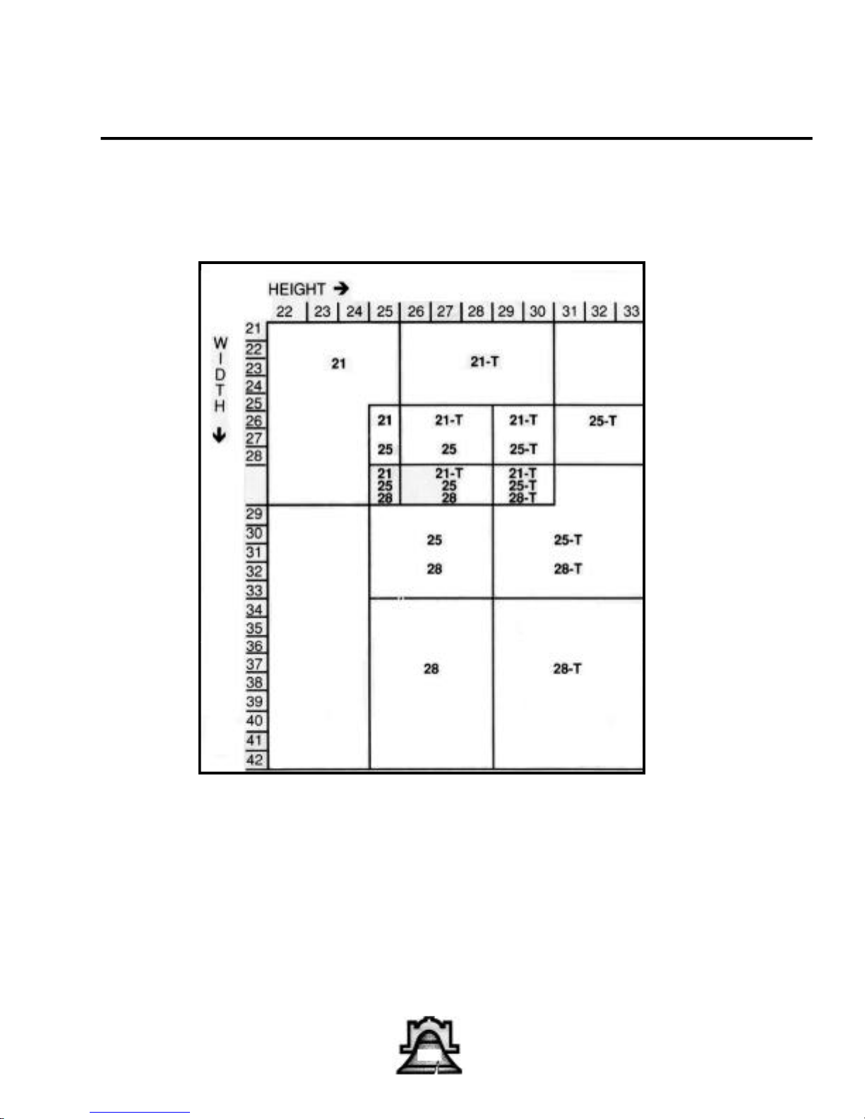
Bellfires® Firebox Dimension Sizing Chart
Bellfires® Quick Reference Chart
Models 21, 25, and 28 (includes tall)
Bellfires® BM & BMR
Use this chart to determine
which Bellfires® size firebox
to install.
5
Page 6
Bellfires® BM & BR
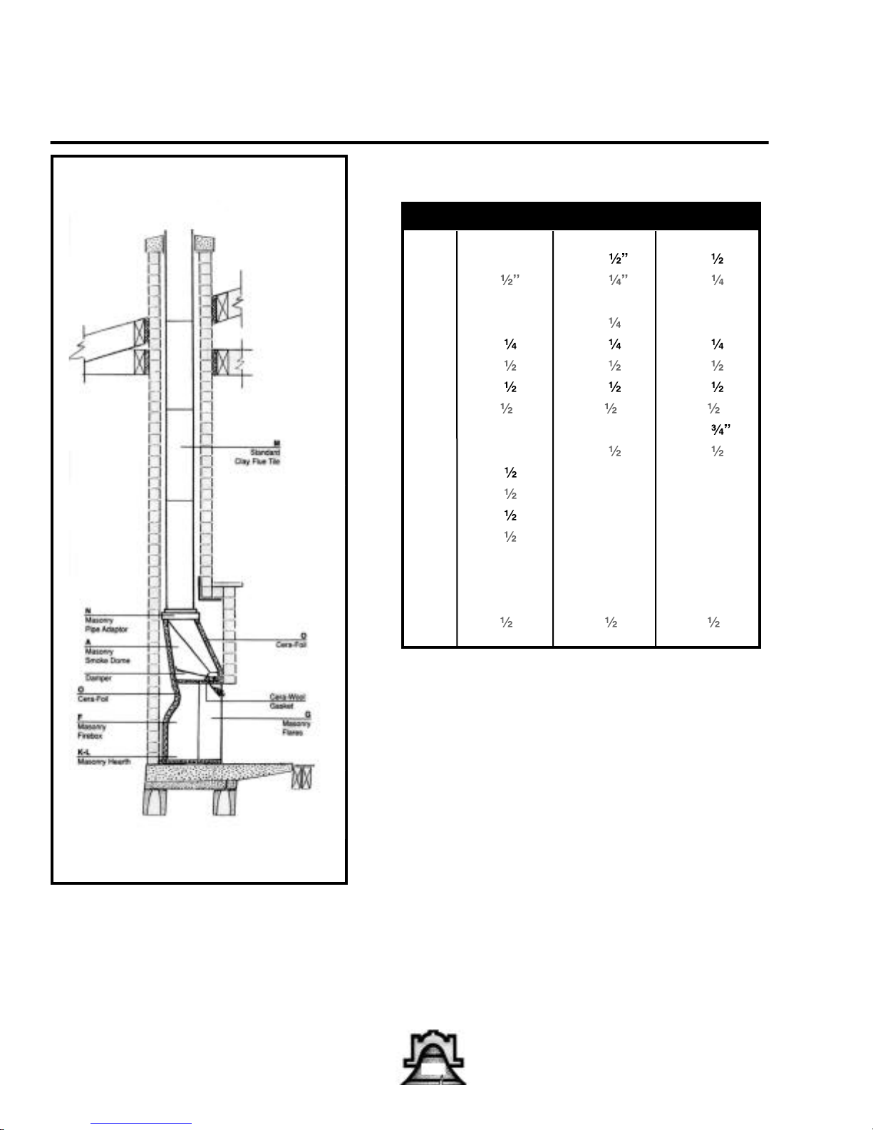
Essential Components of a BM Installation
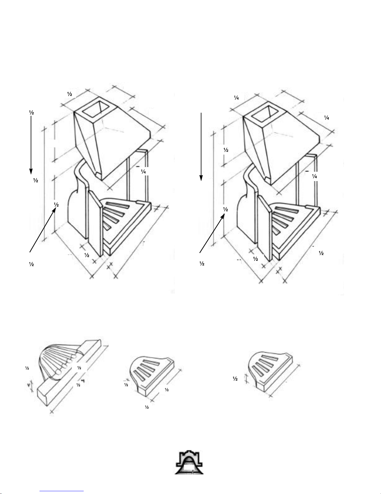
BM 21 BM 25 BM 28
A 16” 20 20 ”
B 9 12 12 ”
C 10” 9” 9”
D 11” 13 ” 14”
E 23 ” 26 ” 29 ”
F 25 ” 28 ” 28 ”
F tall 30 ” 33 ” 33 ”
G 8 ” 8 ” 8 ”
H 17” 21” 19
I 23” 27 ” 31 ”
J 41 ” 49” 49”
J tall 46 ” 54” 54”
K 20 ” 25 29”
L 31 ” – 42”
M 7” 7” – 8” 8”
N 7” 7” – 8” 8”
O 1” 1” 1”
Q 4 ” 4 ” 4 ”
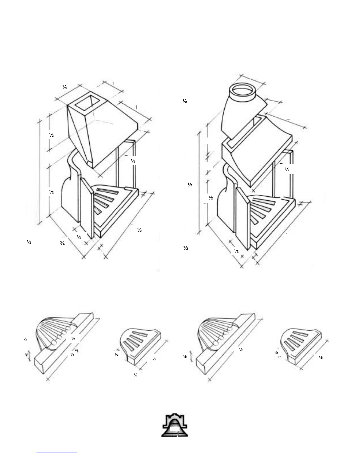
The Bellfires® cutaway diagram at the left shows components necessary for a complete BM installation.
The key above shows specifications for individual models.
6
Page 7
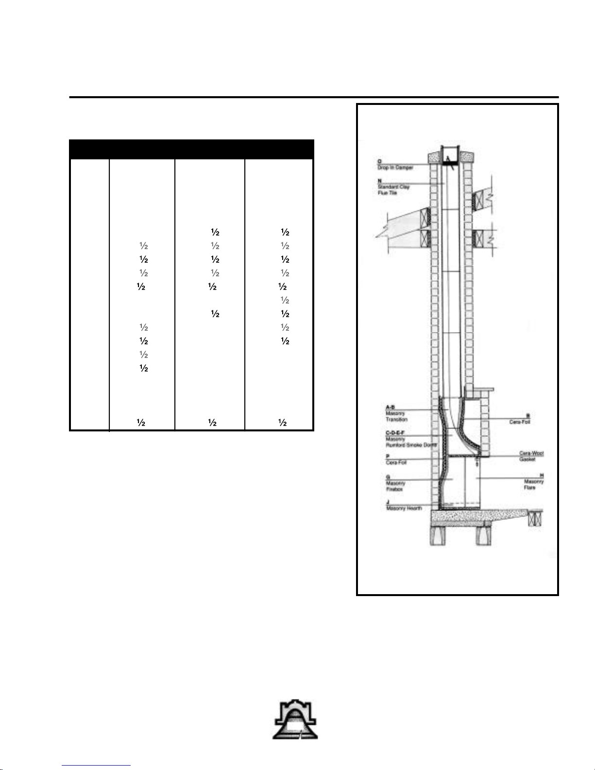
Essential Components of a BMR Installation
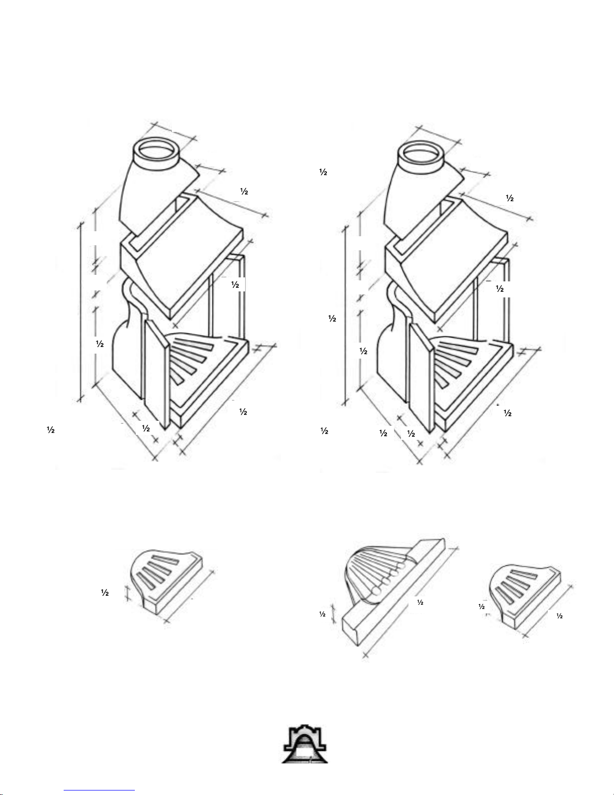
BM 21R BM 25R BM 28R
A 7” – 8”
B 12” – 14”
C 10” 14” 14”
D 7” 7” 7”
E 16” 18 ” 18 ”
F 32 ” 39 ” 39 ”
G 25 ” 28 ” 28 ”
G tall 30 ” 33 ” 33 ”
H 9 ” 9 ” 9 ”
I 17” 21” 19 ”
J 23” 27 ” 31 ”
K 47 ” – 56 ”
K tall 52 ” – 61 ”
L 20 ” 25” 29”
M 31 ” – 42”
N 7” 7” – 8” 8”
O 7” 7” – 8” 8”
P 1” 1” 1”
Q 4 ” 4 ” 4 ”
Bellfires® BM & BMR
The Bellfires® cutaway diagram at the left shows components necessary for a complete BMR installation.
The key above shows specifications for individual models.
7
Page 8
Bellfires® BM & BR
BM 21 Tall
46 ”
41 ”
BM 21 Tall
30 ”
16”
25 ”
9 ”
17”
8 ”
10”
23 ”
23”
11”
BM 25 Tall
54”
49”
BM 25 Tall
33 ”
9”
12 ”
13 ”
20 ”
26 ”
28 ”
27 ”
8 ”
21”
BM 21 Tall & Standard
4 ”
Two Piece Hearth One Piece Hearth
31 ”
4 ”
31 ”
4 ”
20 ”
BM 25 Tall & Standard
4 ”
25”
One Piece Hearth
8
Page 9
BM 28 Tall
54”
12 ”
9”
14”
BM 21R Tall
52 ”
Bellfires® BM & BR
7”
7”
16”
20 ”
29 ”
49”
28 ”
BM 28 Tall
33 ”
8 ”
19 ”
31 ”
BM 28 Tall & Standard
12”
10”
47 ”
BM 21R Tall
30 ”
25 ”
17”
9 ”
32 ”
23”
BM 21R Tall & Standard
4 ”
Two Piece Hearth
31 ”
4 ”
31 ”
One Piece Hearth
4 ”
20 ”
31 ”
4 ”
Two Piece Hearth
4 ”
20 ”
One Piece Hearth
9
Page 10
Bellfires® BM & BR
8”
BM 25R Tall
33 ”
14”
28 ”
21”
9 ”
7”
18 ”
39 ”
27 ”
BM 28R Tall
61 ”
14”
14”
56 ”
28 ”
BM 28R Tall
33 ”
19 ”
7”
18 ”
39 ”
31 ”
9 ”
BM 25R Tall & Standard
4 ”
25”
One Piece Hearth
BM 28R Tall & Standard
31 ”
4 ”
Two Piece Hearth
10
4 ”
One Piece Hearth
20 ”
Page 11

Bellfires® BM & BR
11
Page 12
Bellfires® BSV
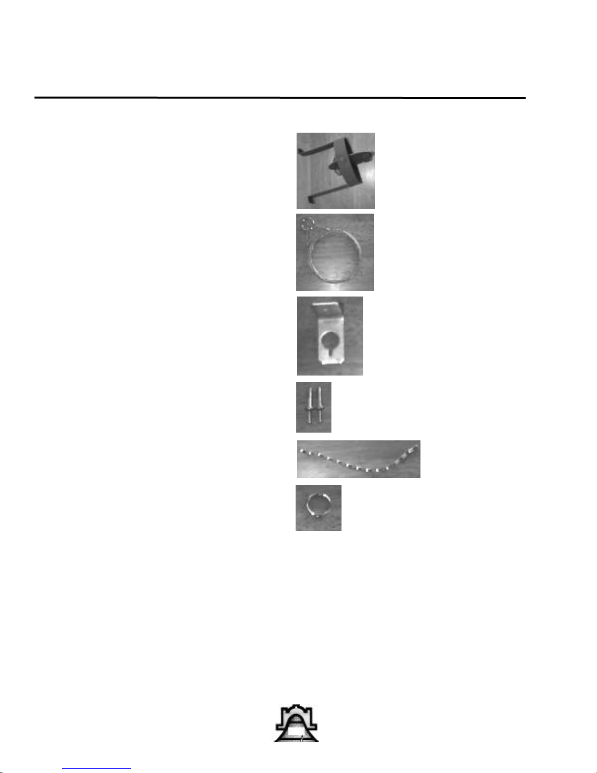
BSV Spider Damper Parts
For use with BMR Bellfires; add to order
1- Drop In Damper
28' Stainless Steel Cable
1 -Bracket
2 -Hammer Drive Pins
1- Stainless Steel Sash Chain
1 -Stainless Steel Ring (attach to chain)
1 -Stainless Steel Clamp (attach to cable)
You need....
Ladder
Hammer Drill
1/4 inch Masonry Drill Bit
Safety glasses
Wire Cutters
Marker
Flat Gasket or Silicone Caulk
12
Page 13
Bellfires® BM & BMR
Safety Guidelines
A. Bellfires® fireplaces are not approved for use in mobile homes.
B. There must be an air space clearance between the outermost portion of any section of the chimney system and
any combustible surface. Although two inches is a typical clearance, adhere to the requirements set forth by the chimney manufacturer. Combustible surfaces include: ceilings, joists, flooring, walls, electrical wiring, insulation and roof
structures.
C. Never fill any required air space with insulation or other material.
D. The chimney system must be vented to the outside.
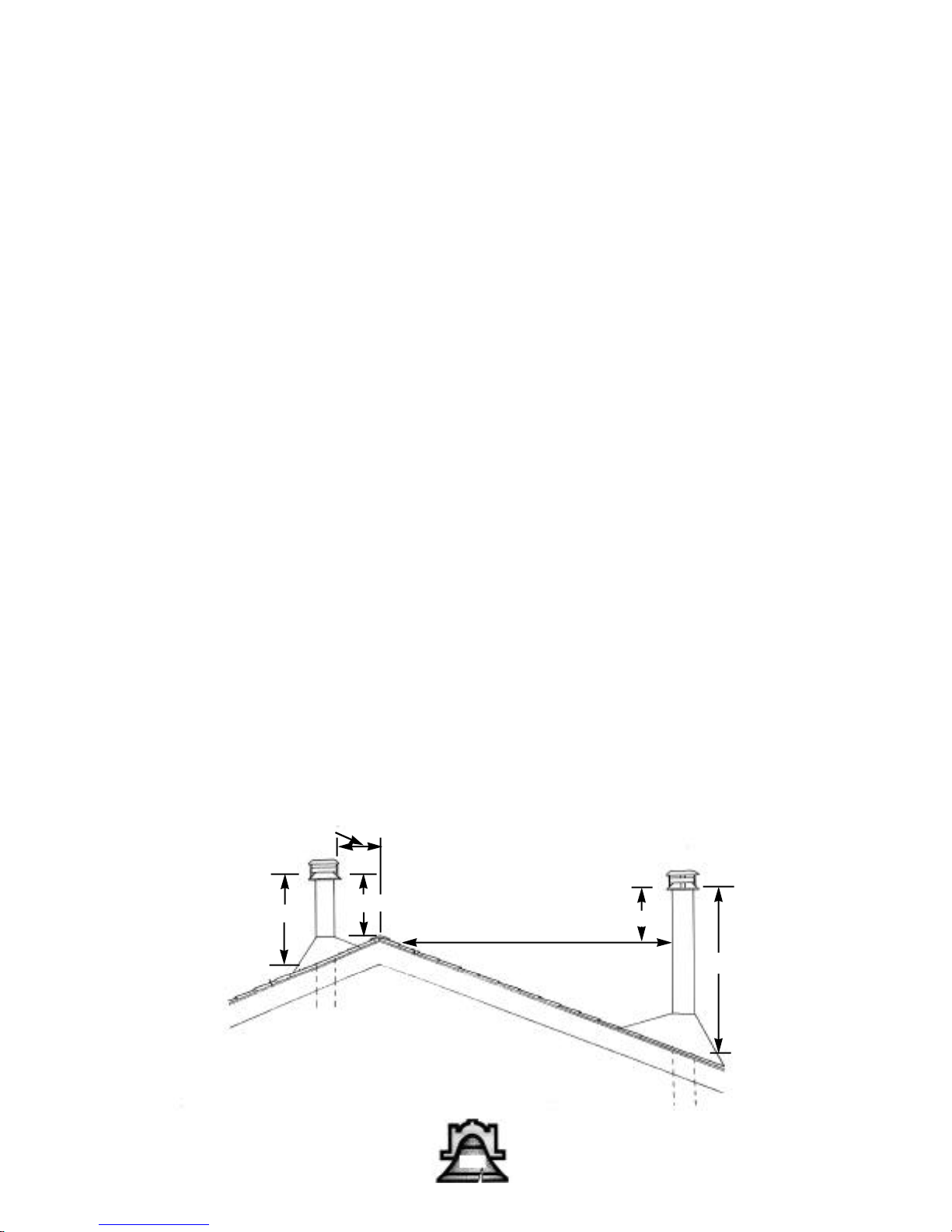
E. The chimney must extend at least three feet (900mm) above the roof and at least two feet (600mm) above any
portion of the roof within 10 feet (3m).
F. Maximum chimney height from the top of the firebox to the top of the chimney should not exceed 40 feet when
supported solely by the fireplace, or 90 feet when resupported at or above 40 feet according to the chimney manufacturer's resupport specifications.
G. Minimum chimney height from the top of the firebox to the top of the chimney must be 10 feet.
H. The chimney must not be inclined more than 30 degrees from vertical. Greater angles result in hazardous
deposits of soot and ash in flue.
I. A maximum of two offsets (4 elbows total) is allowed in a chimney.
J. Firestops and joist shields must be used at each floor level through which the chimney rises.
K. There should not be any forced air furnace registers in the room within ten feet of the fireplace. They can cause
negative pressure and create chimney down-drafts.
L. Never mix parts of one chimney system with those of a different manufacturer. Do not install damaged chimney
parts. Remember, more fires are caused by chimneys than by solid-fuel appliances.
M. Practice good workmanship. Sloppy work could jeopardize the safety of the installation.
Less than 10 feet
3 feet minimum
2 feet minimum
Ridge
10 feet or more
2 feet minimum
3 feet minimum
Chimney Height Requirements
13
Page 14

Bellfires® BM & BR
Materials List
BLOCK AND BRICK SHELL NOT LISTED.
Wing walls: 12-10" X 8" X 16" Block
4- 4" X 8" X 16" Block
2- 4' X8" X 56" Precast concrete lintels
4- Bags perlite for unit only
Brick ties
8" I.D. round flue liners or thimbles.
2- bags light masonry cement.
BM 28 with two piece hearth.
1- masonry pipe adaptor.
1" X 24" X 25’ 8 lb. density CERAFOIL.
1/4" CERAFOIL gasket and hearth pad.
1- ROLL CERAFOIL tape.
1- 2 gallon pail SUPER CEMENT.
14
Page 15
Bellfires® BM & BR
READ INSTRUCTIONS CAREFULLY BEFORE BEGINNING.
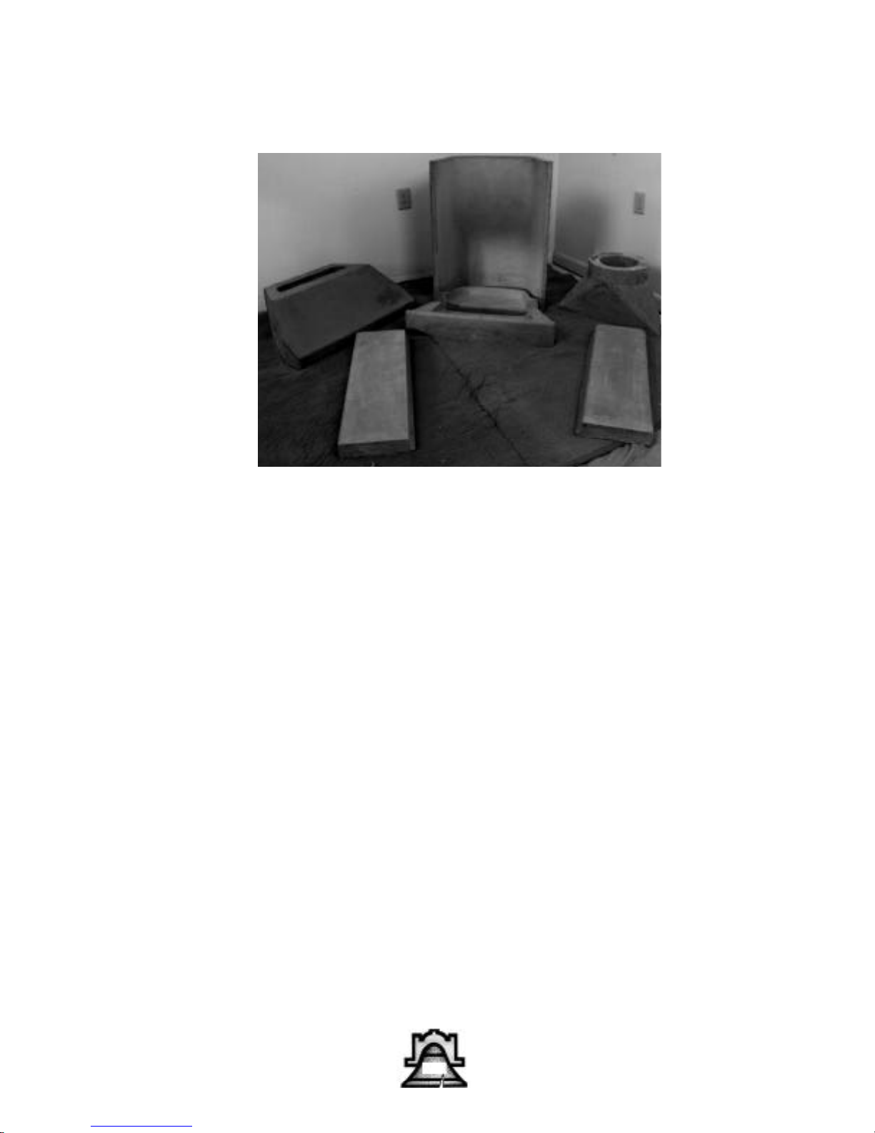
Thank you for purchasing the Bellfire masonry unit, BM 28 TALL. These
instructions are specified for a 36” finished opening. But dimensions can
be altered to accommodate Models BM 21, BM 25, and the smaller
height units.
After determining the fireplace location, check with municipal codes to
assure proper depth for footing requirements. Pour footer base minimum
4’ wide X 8’ Long X 12" thick using a 5 bag footer mix.
Construct block base minimum 32" X 64" O.D., finished size, up to
desired height of fireplace floor. Allow 4" ledge at ground level for veneer
material, brick or stone. Block width walls should be laid inside of base
for support.
15
Page 16
Bellfires® BM & BR
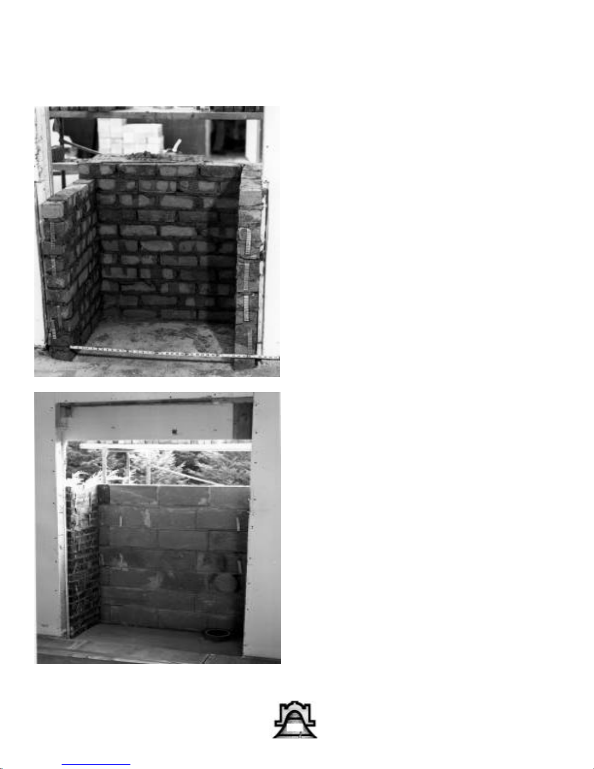
Cut the house wall
rough opening at 56”
wide X 60”high.
(FIG.2A) Pour a concrete pad on block base
4”-6” thick and level off.
If additional flue chamber is needed at lower
level, build along with
block base to a point
higher than finished
concrete pad. (FIG.2A
2B) The concrete pad
must cantilever into
formed floor joists, 24"
for hearth. The BELLFIRE performs best at
floor level although a
raised hearth may be
used.
At this point the brick or
stone veneer and 4”
block back wall is built
to a height of 56" above
concrete pad. Use brick
ties for fastening wing
walls. (FIG.2, 2A)
16
Page 17
Bellfires® BM & BR
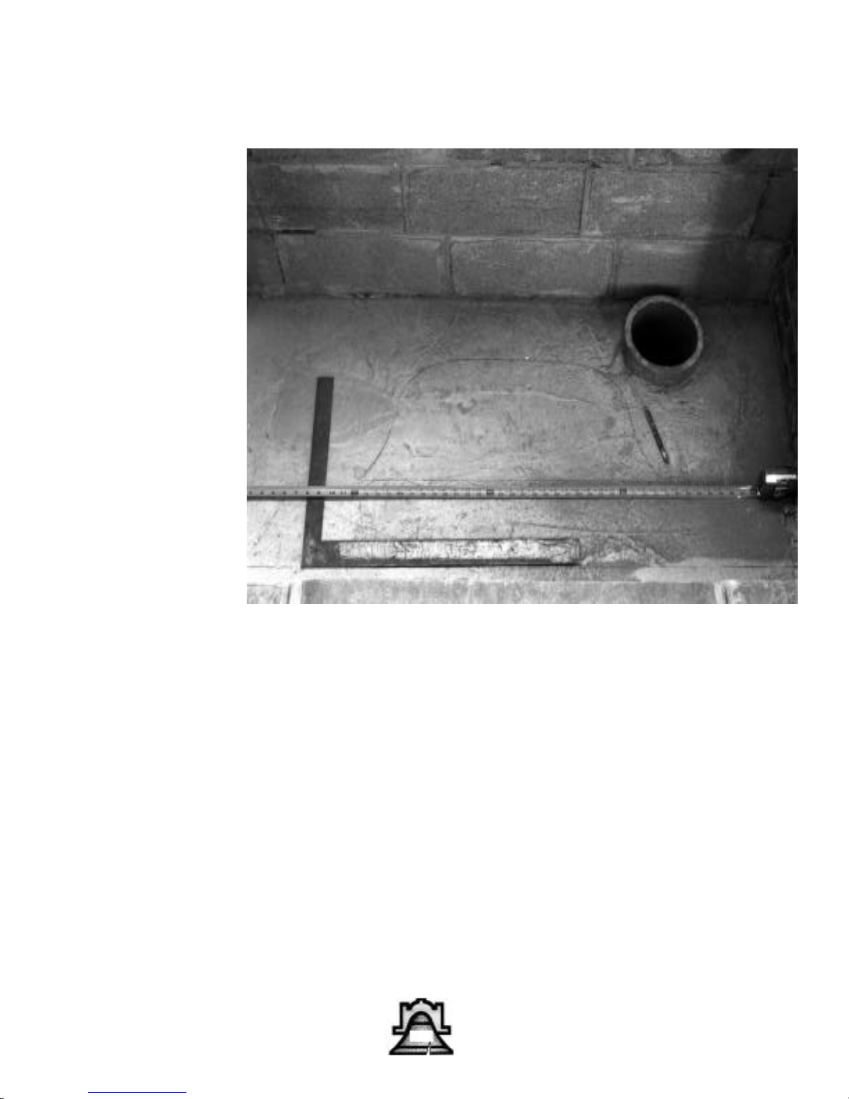
Straight edge a pencil line off interior finished walls.
This line is the back of interior veneer material and also
the extension of the BELLFIRE flares.(FIG 2B)
17
Page 18
Bellfires® BM & BR
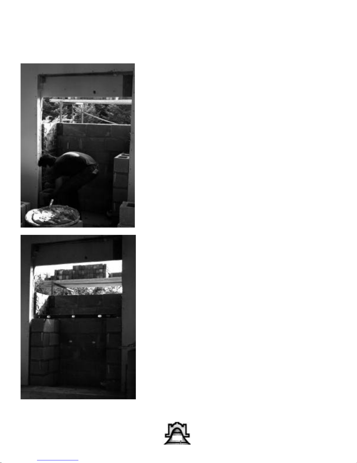
With 10" block, build two
wing walls against rough
opening, flush with interior
wall and pencil line. Use
brick ties. (FIG.3) Stop wing
walls at nearest block height
above fire box, 40" on BM 28
TALL (FIG.3A)
18
Page 19
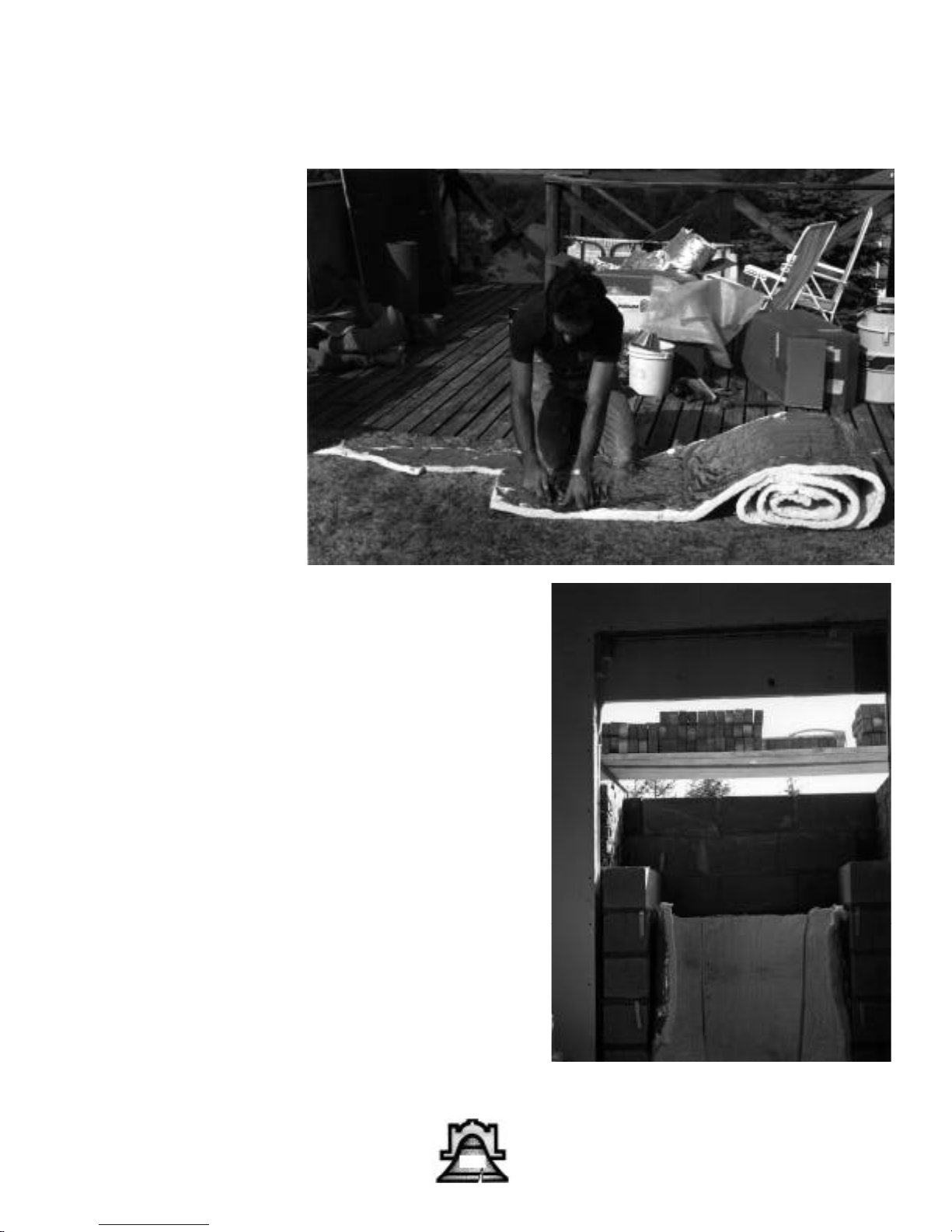
Using a sheet rock
knife, measure and
cut three 33” tall sections of 1” Cera-Foil
ceramic fibre high
temperature insulating
blanket. Allow 6” additional width on each
side to insulate firebox
extension flares. Cut
foil side and stand in
place between wing
wall. (Fig. 4, 4A).
Bellfires® BM & BR
Place 1” thick sections of
Cera-Foil in place between
wing walls. This technique
accomplishes the following. The ceramic fibre
insulating hot face forces
the refactory firebox to
store more heat, creating
a cleaner and hotter burning firebox. It also allows
for a thermal expansion
cushion with a built-in foil
faced moisture barrier
when the fireplace is
exposed to the outside.
(Fig 4A).
19
Page 20
Bellfires® BM & BR
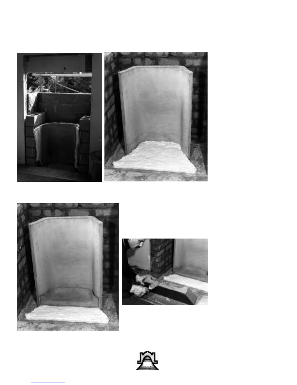
Install the refractory fire
box between wing walls
and position flare extensions for proper
centering. Remove side
flares after firebox is
properly centered.
(FIG.5)
20
Cut 1/4” CERAFOIL
insulating blanket to
shape of the two piece
hearth, installing
foil face down. (FIG.6)
With masonry saw blade
cut outer piece evenly on
both ends for proper rib
alignment. Install two
piece hearth.
(FIG.6A,6B)
Page 21
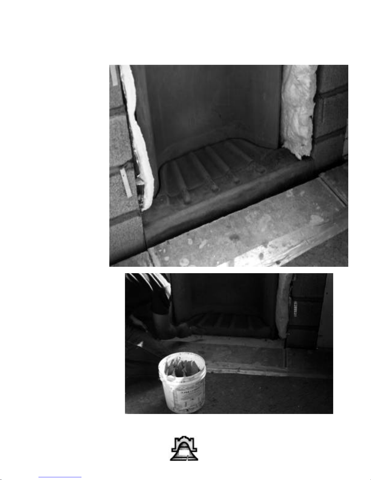
Note on 6-A the preferred method of installation of side flare panels
and front stretcher brick
would be to rest flares
on pad and cut stretcher
to matching angles. 7-A
shows a straight cut
stretcher brick with cut
shorter panels on top.
Bellfires® BM & BR
21
Page 22
Bellfires® BM & BR
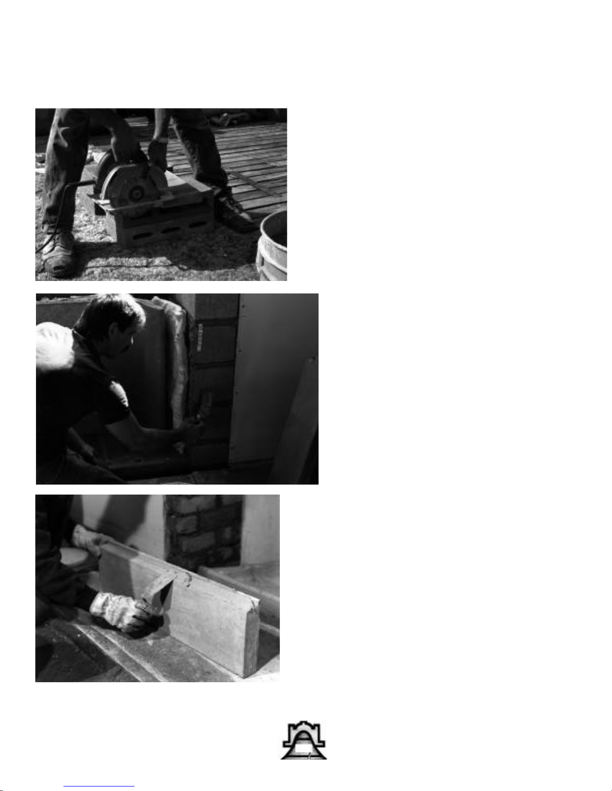
Cut bottom of flare
extension to angle of
hearth. Make sure the
top is level with fire box.
(FIG. 7,7B) With SUPER
CEMENT, butter the flare
groove, the edge of block
wing wall. and bottom of
flare. Secure flares in
place. (FIG.7A) Cut off
excessive cement. Flares
should be flush with
block wing walls.
22
Page 23
Bellfires® BM & BR
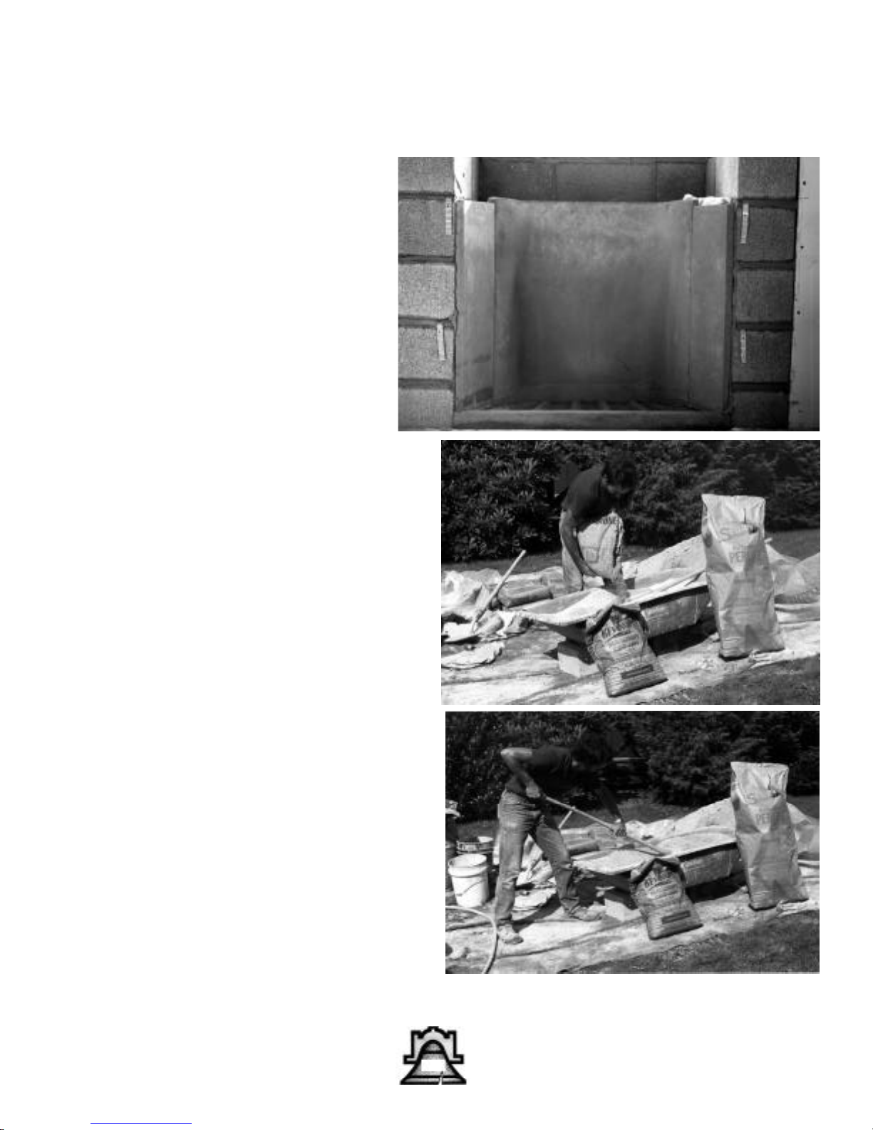
Mix coarse pea size perlite with light masonry
cement at a ratio of 7:1
(7 perlite, 1-masonry
cement). No sand is
needed. (FIG.8) Before
adding water, mix ingredients thoroughly. Slowly
add water, bringing mixture to a potting soil consistency. (FIG.8A)
23
Page 24
Bellfires® BM & BR
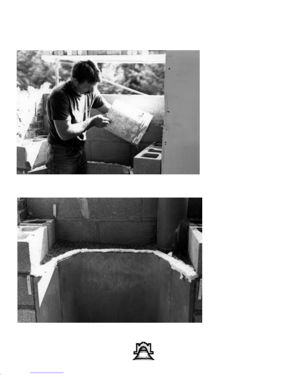
Before pouring mixture,
make sure the 1" CERAFOIL is snugged
against back of fire box.
Pour mixture behind fire
box tamping lightly in
between pours. Fill open
cores in block wing walls
also. (FIG.8B, 8C)
Note CERA-FOIL used
as a gasket/expansion
joint at top of firebox 23”. Peel off foil backing.
24
Page 25
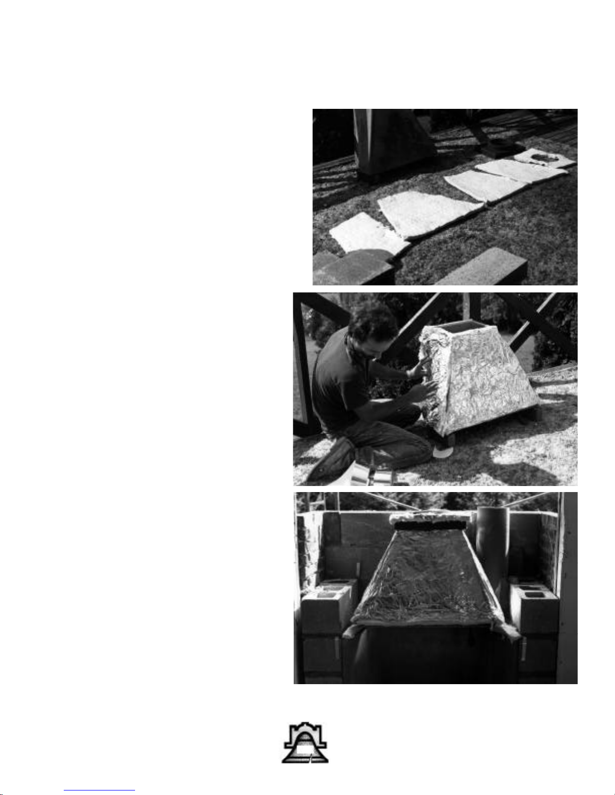
Cut 1" CERAFOIL pieces
for masonry canopy, over
lapping outside edges.
(Fig. 9) with CERAFOIL
tape. Adhere insulation to
masonry canopy. (FIG.9A
Make sure the CERAFOIL pieces are 1” larger
than the outside of the
masonry canopy so that
you can overlap the corners. Use CERA-FOIL
tape to adhere CERAFOIL to the canopy.
Bellfires® BM & BR
BM specific directions
Cut 1/4" CERAFOIL in 2"
wide strips, making a gasket in between firebox
and masonry canopy.
Remove foil from insulation. Install canopy on top
of firebox, aligning inside
back walls on both units.
(FIG. 10)
With 1" CERAFOIL, insulate around top round
pipe adaptor. Use 1/4"
insulation gasket between
both units and secure in
place (FIG. l0A)
25
Page 26
Bellfires® BM & BR
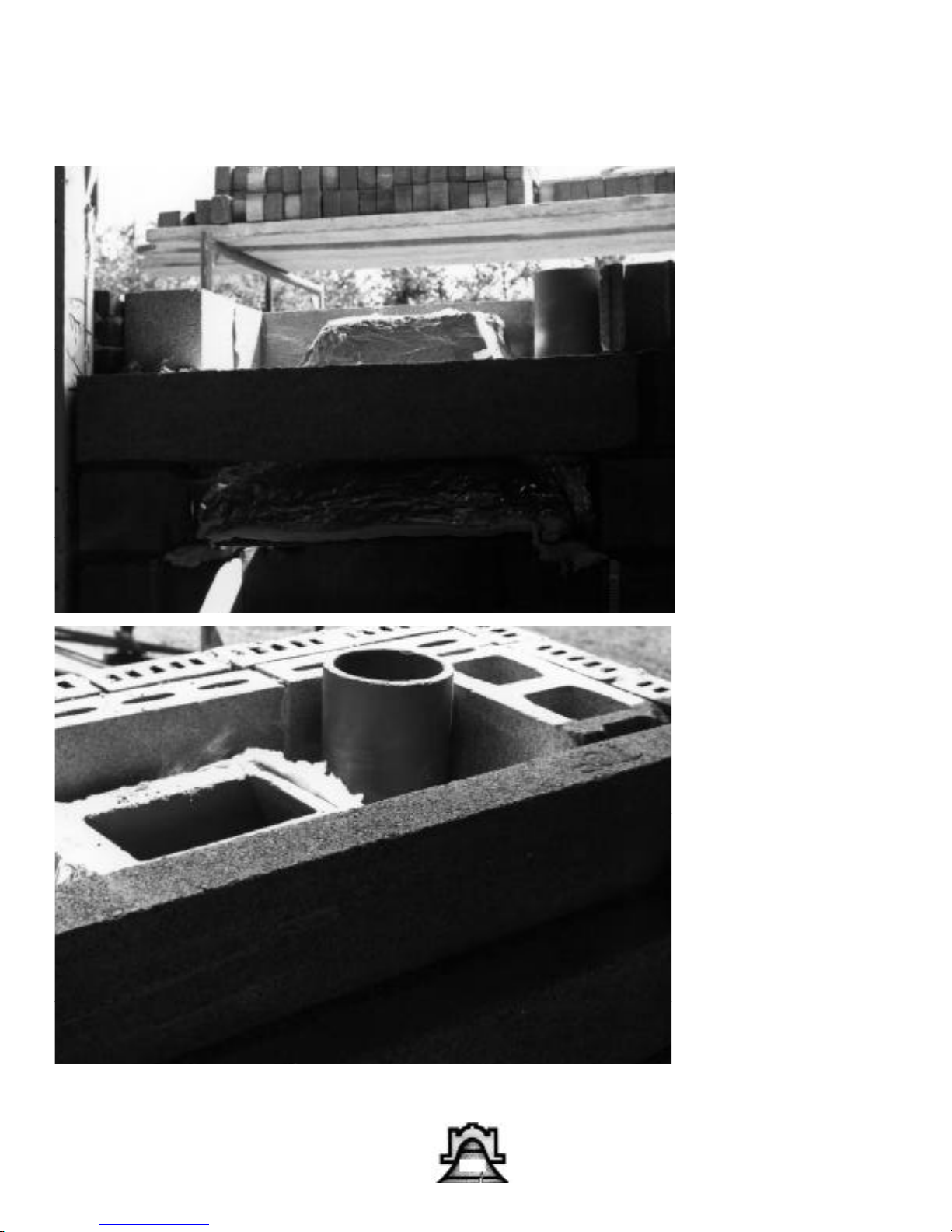
Lay another coarse of
10" block on wing walls
leaving 4" open on outside edge. Span across
outer edge of wing walls
with one 4" x 8" x 56"
pre-cast concrete lintel
(FIG. 11) Pour the void
between lintel and
masonry dome with perlite mixture. Lay the second 4" X 8"X 56" precast lintel in place, offsetting the first one by
4".
26
Page 27
Bellfires® BM & BR
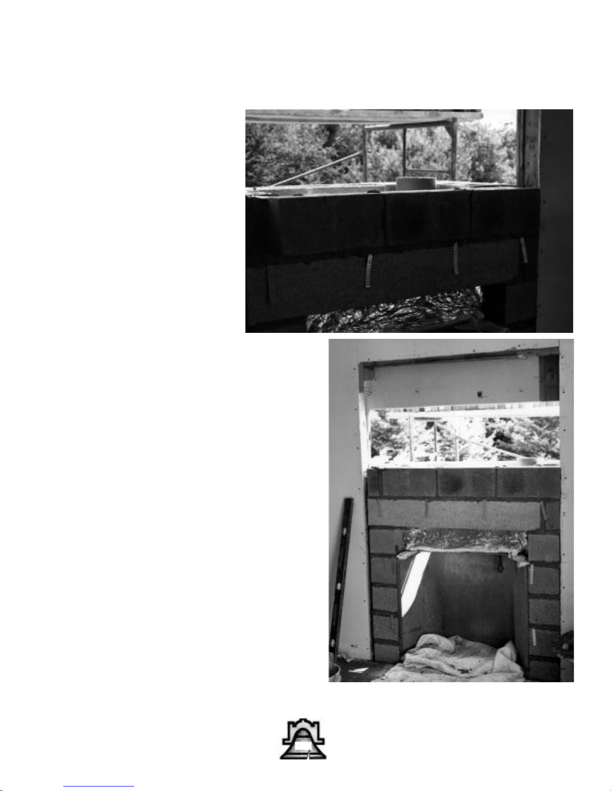
Lay one block on each
wing wall, filling the gap
(FIG.11) on top of offset.
Lay a coarse of 4" block
leveling off the top. Don't
forget brick ties for the
veneer work. (FIG. 11B,
11C)
27
Page 28
Bellfires® BM & BR
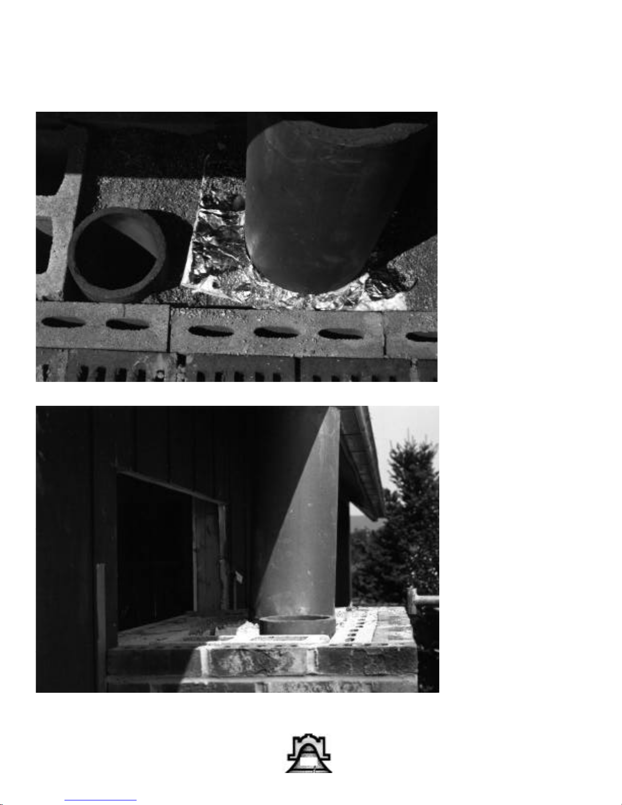
Using SUPER CEMENT,
butter the bottom of the
flue liner and secure to
top of unit. (FIG.12) Fill
the remaining void with
perlite mixture.
(FIG.12A, 12B)
From this point up the
chimney is built in a normal fashion, although
the void between the
filler block and the liners
should be filled with perlite mix. This assures
expansion capabilities
and insulating properties. After chimney is
completed, return to the
inside for the veneer of
your choice.
28
Page 29
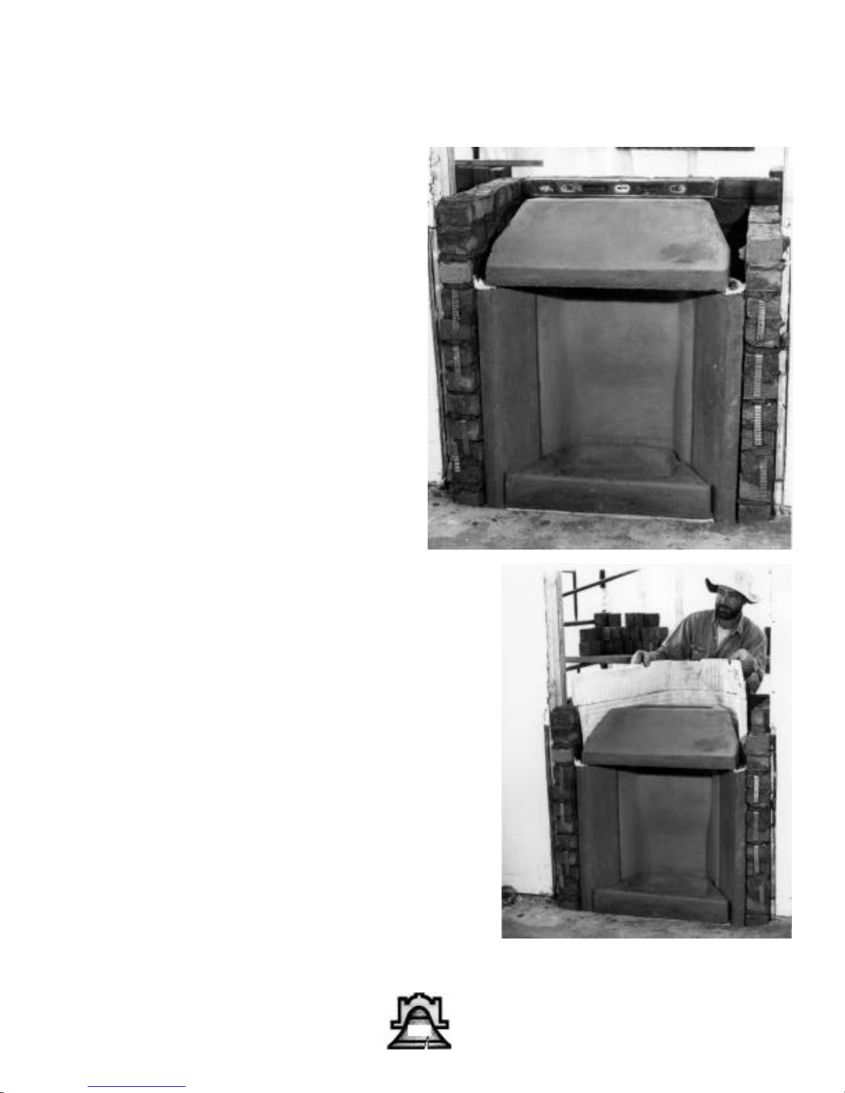
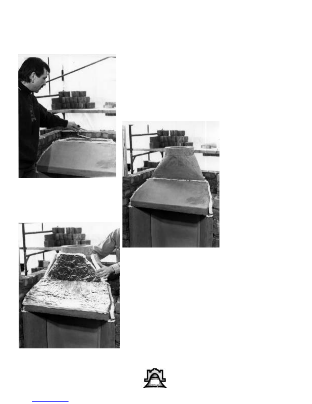
Install refractory dome on
top of firebox aligning
inside back walls flush on
both units. (Fig 9). Make
sure the CREA-FOIL
pieces are 1” larger than
the outside walls of the
masonry dome, so you
can overlap the corners.
(Fig. 10).
Bellfires® BM & BR
BR specific directions
29
Page 30
Bellfires® BM & BR
Using SUPER CEMENT
refractory mortar, butter
top of refractory dome.
(Fig ). Place refractory
turbo transition on top of
refractory smoke dome,
aligning inside back
walls flush on both units.
(Fig ). With 1” CERAFOIL, insulate around
refractory turbo transition. (Fig ).
30
Page 31
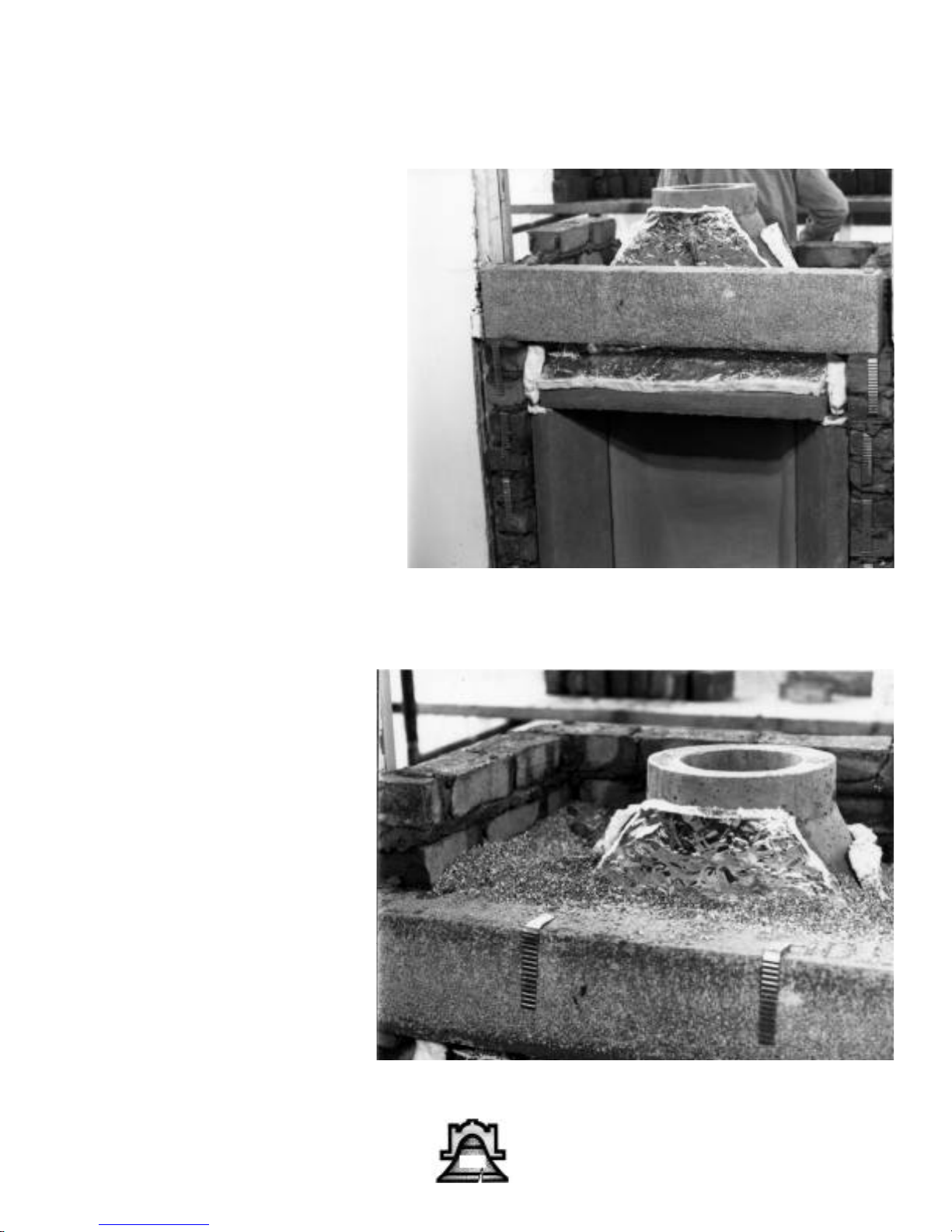
Using SUPER CEMENT
refractory mortar lay
another coarse of 10”
block on wing walls leaving 4” open on outside
edge. Span across outer
edge of wing walls with
one 4” x 8” x 56” precast
concrete lintel. (Fig ).
Pour the void between
lintel and masonry dome
with perlite mixture. Lay
the second 4” x 8” x 56”
precast lintel in place, offsetting the first by 4”.
(Fig. ).
Bellfires® BM & BR
31
Page 32
Bellfires® BM & BR
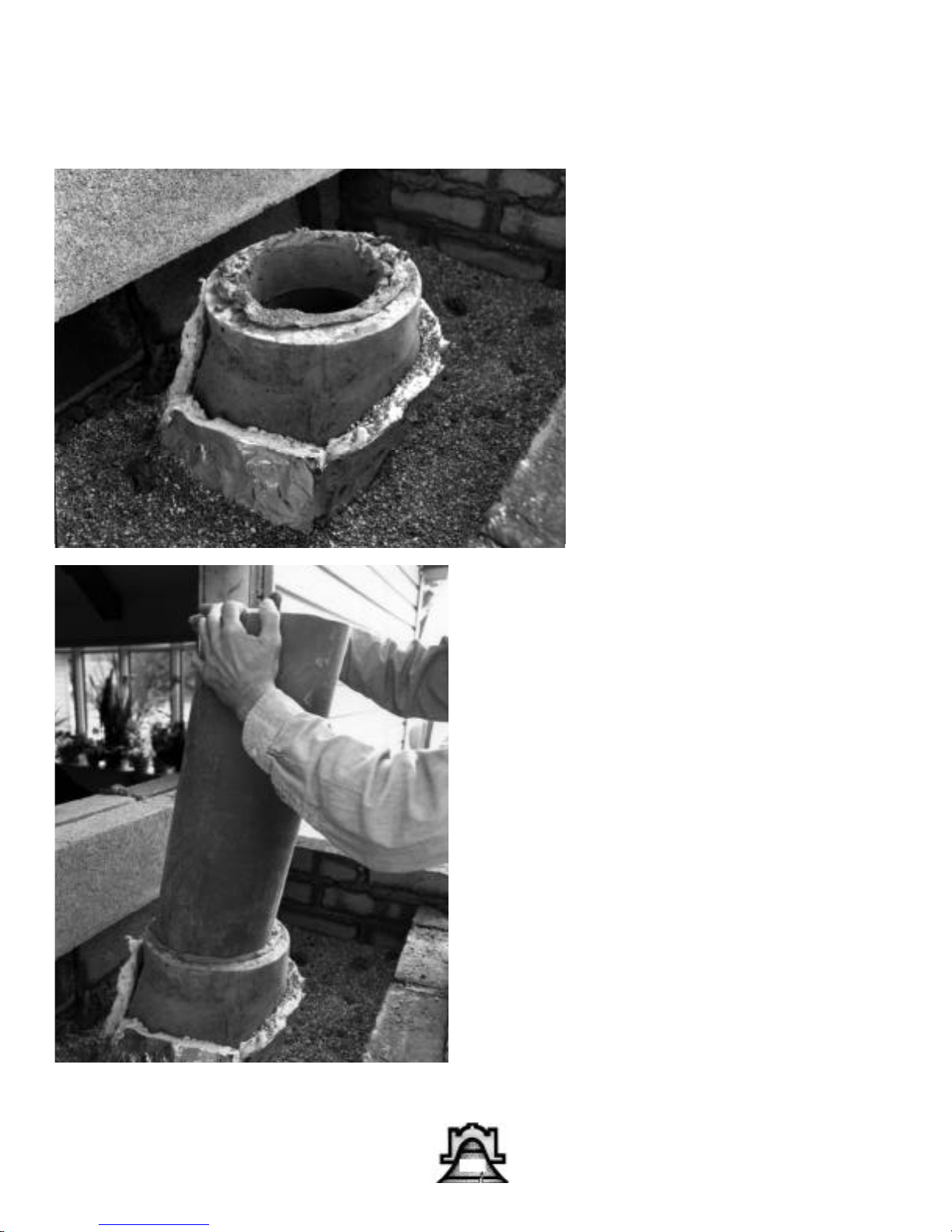
Using SUPER CEMENT,
butter the bottom of the
flue liner and secure to
top of unit. (FIG.12) Fill
the remaining void with
perlite mixture. (FIG.12A,
12B)
From this point up the
chimney is built in a normal fashion, although the
void between the filler
block and the liners
should be filled with perlite mix. This assures
expansion capabilities
and insulating properties.
After chimney is complet-
ed, return to the inside for
the veneer of your
choice.
32
Page 33
Bellfires® BMR Spider Damper
25-1
25-3
Round
chimney
liner
25-4
25-2
25-5
PLEASE
NOTE!!!
The Spider Damper® may
only be used with the
Bellfires® BMR model. The
Bellfires® BM is usually
installed with rectangular
tile and the Spider Damper
is only usable with round
liners. We recommend
using a rectangular top
mounted damper such as
the Lyemance Locktop.
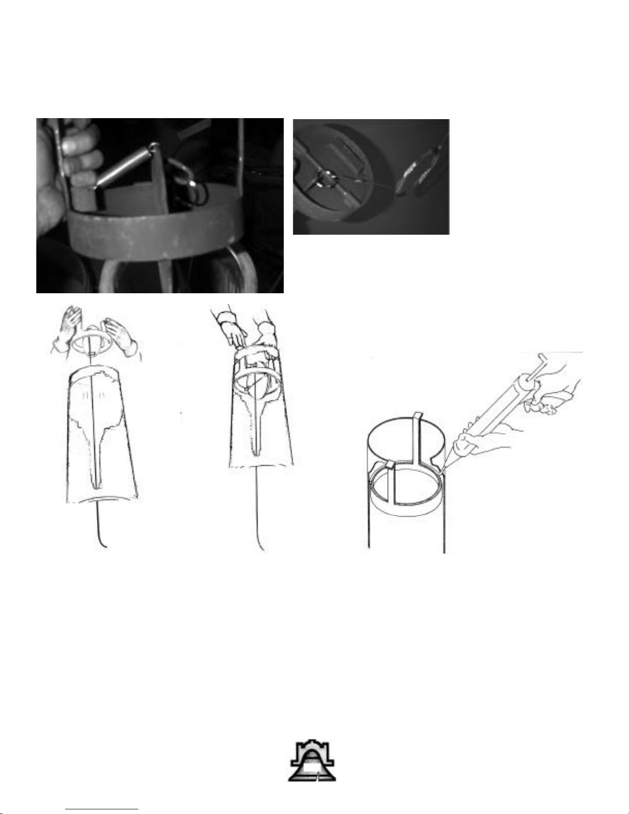
After the chimney liner has been installed, but before the chimney cap is placed, the top mounted Spider
Damper must be installed. The Spider Damper is placed in the top section of the chimney liner.
The Spider Drop-in Damper (25-1) (Part #21) installs typically like other top mounted dampers. The bottom
hook-up is also typical. Attach the ring on the 28’ stainless cable (Part #22) to the underside ring of the Spider
Damper. (25-2) The installer must go to the roof and place the Spider Drop-in Damper inside the top section of
the chimney liner until handles of damper don't go any further down. (25-3, 25-4) Unroll cable, dropping it all
the way down the flue until cable reaches the firebox. The important installation step to be observed is as follows: check for tightness in between flue walls and outside damper. Any air clearance should be sealed with flat
gasket or silicone caulk. (25-5) Check damper plate to be sure it moves freely. Because blade is counterweight,
damper should always be in the opening position.
33
Page 34
Bellfires® Spider Damper
26-1
3”
20”
26-2
Stainless steel clamp
26-5
26-3
26-4
Hearth
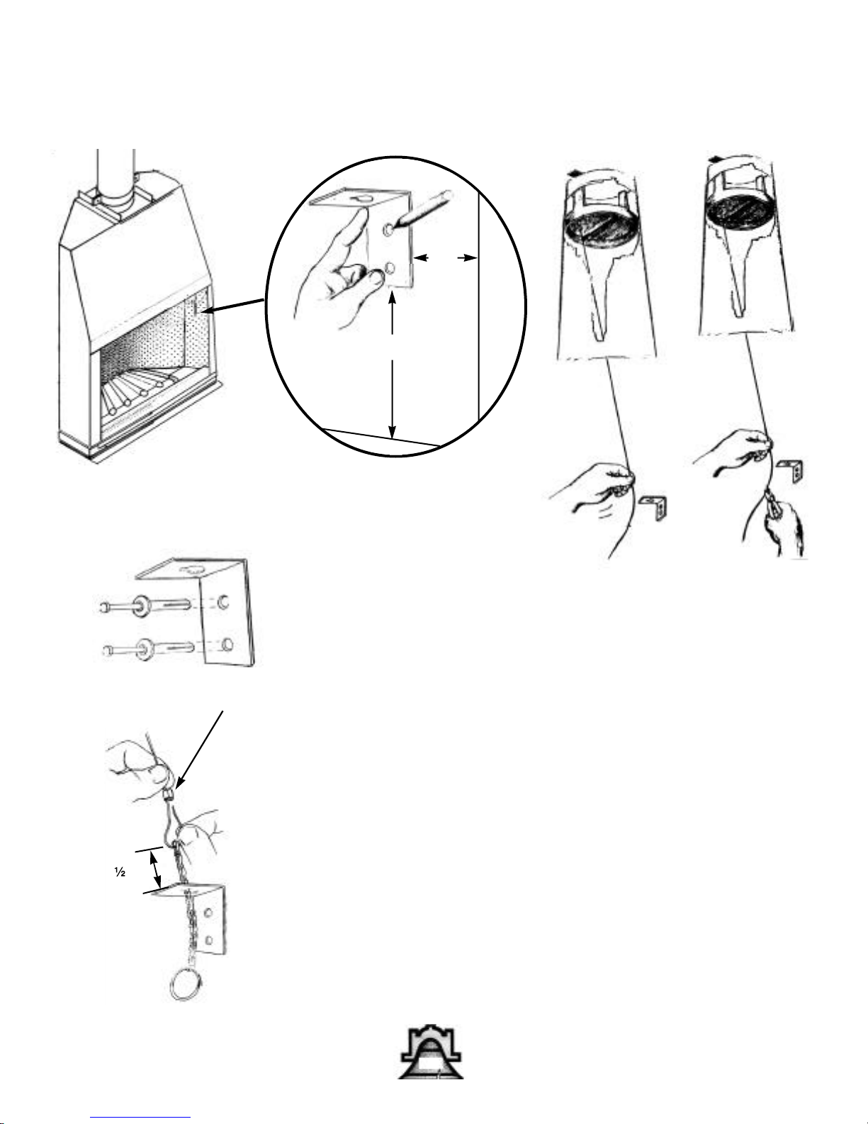
Now, go back inside to the BMR firebox. Take the "L" bracket (Part #23)
and place it at wall of firebox (26-1) about 20" from hearth and no less
than 3" from outside opening. With a marker, mark the two openings of
the “L” bracket onto the side of the firebox. (26-1) Be sure to wear your
safety glasses. Using a masonry drill bit, drill two 4” inch holes into firebox on the marks you made. Attach "L" bracket with hammer driver.
(Part #24) (26-2). Close damper by pulling cable until slight tension is
felt. (26-3).
Cut stainless steel wire about 12 inch lower than the horizontal bar of
bracket. (26-4).
1 ”
Take opposite end to ring of stainless steel chain and slide it through
bracket from bottom to top. Slide end of cable through first link of sash
chain (Part # 25)(26-5) and through clamp (Part #26). Attach to cable by
squeezing with pliers. At this time damper should remain closed.
Position clamp and be sure that first link of chain is 12 inches over the
horizontal of bracket. After the attach clamp is secure against cable your
Spider Drop-in Damper is ready to be used.
34
Page 35
Build the World’s Best Fire
Top Down Burn
Handy Items to Have
A Fireplace Screen
A Kindling Ax (Be careful)
Stove Gloves
An Ash Rake
Think of your fuel load as three component parts:
The Base Course (can be unsplit if proper diameter)
The Middle Course (split)
The Top Courses (split finer)
THIS TYPE OF FIRE IS NOT RECOMMENDED FOR
THE FIRST EIGHT TO TEN FIRES. BELLFIRES® MUST
BE GRADUALLY BROKEN IN AND CURED WITH
SMALL FIRES FOR THE FIRST EIGHT TO TEN FIRES.
DO NOT OVERFIRE YOUR BCC!!
A fireplace grate is not necessary with the BCC 28. A
grate increases your critical burn rate allowing logs to
burn faster than normal. Logs burn best in contact
with hot firebrick in a bed of wood ashes.
Helpful Hints & Precautions before you start:
Make sure your fireplace and flue have been inspected
for fire worthiness and are cleaned if found dirty (full
of flammable cresosote), by a reputable Chimney
Sweep. Make sure the damper is open. The damper is
controlled from the keyed stainless cable and ring
installed to either side of the firebox sidewall. Pull
down and unhook to release the tension of the stainless steel cable. Pull down and rehook the cable to
close the damper. There are no other settings than
completely open or completely closed. If your fireplace and flue are located on an outside wall or, when
the damper is open, you feel a flow of frigid air rushing down into the room, pre-heat the flue with a sheet
of lit newspaper. Hold the lit newspaper high into the
damper area, wearing a pair of stove gloves for protection. This will reverse the cold air plug present in the
flue, creating a strong updraft with no smoke into your
room. As soon as the newspaper is burned up, light
your newspaper on top of your fuel load.
Approximately 3-4 hours later when you have a nice
bed of hardwood coals, use a fireplace rake to push the
coals against the rear wall of the firebox. Next, lay your
new logs, minimum of four, on top of the hot coals, lay
the bottom two horizontally. The top two, a little shorter in length, place front to back approximately 3 inches apart creating a throat.
The greatest volume of smoke and particulate pollution from a wood fire occurs during a cold start up.
Wood fires lit from the bottom, in a conventional manner, promote a dirty burn and waste a large amount of
potential heat in the form of unburned gases.
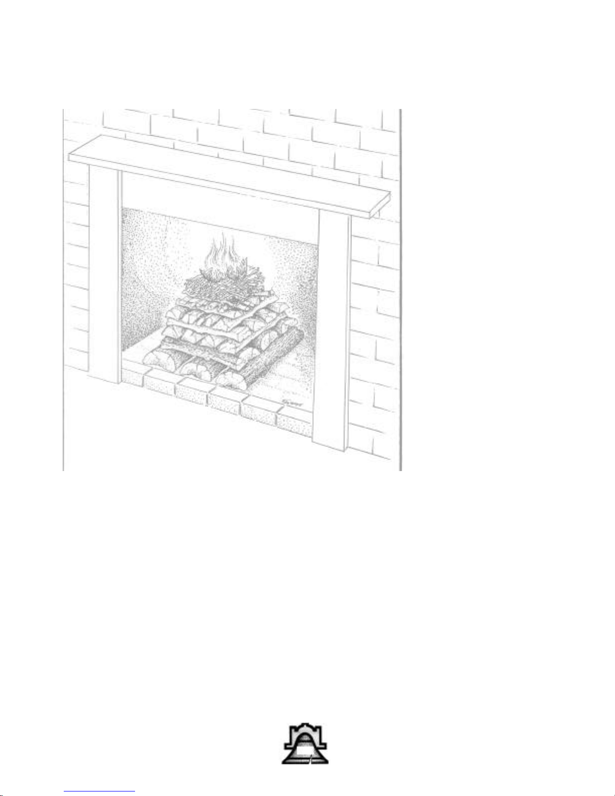
A clean and efficient method for kindling a fire is a
top burn. This almost forgotten ancient European technique places the largest wood at the bottom in a criss
cross crib fashion. As each tier is laid, the criss crossing becomes smaller. Kindling and a small amount of
paper are placed on top and lit.
When the top burn fire is lit, the flames are always
above the fuel load. The smoke and flammable gas
from each tier of wood will always travel up through
the flame and burn, thereby reducing particulate pollution and unburned fuel.
A top kindling fire also produces large and less compacted glowing coals, providing excellent long-lasting
radiant heat.
A top burn fire laid with seasoned hardwood to a
height of eighteen to twenty-four inches will burn
approximately four hours without adding additional
wood. The fire will be mesmerizing as each tier slowly
ignites and burns its way down.
TOP BURN RECIPE
Always start with dry, well-seasoned, split firewood and
kindling. (Ideally seasoned firewood will have a 20%
moisture content. The wood will show radial cracks at
the ends and sound like bowling pins when beaten
together.)
Bottom layer:
Three good sized pieces of split hardwood five to six
inches thick, laid front to back.
Second layer:
Three slightly smaller pieces of split firewood three to
five inches thick, laid side to side.
Third layer:
Four to five smaller pieces of split firewood two to
three inches thick, laid front to back. Keep afternating
and decreasing in size with split hardwood until they
are about one inch thick.
Now alternate two rows with split softwood
(pine, spruce, etc.) until pencil thick. Place a small
piece of newspaper on top and light.
35
Page 36

Operating Instructions & Maintenance
BM, BMR Operating Instructions & Fireplace & Chimney Maintenance
Keep These Instructions
for Future Use
NEVER USE GASOLINE, GASOLINE-TYPE
LANTERN FUEL, KEROSENE, CHARCOAL-
LIGHTER FLUID, OR SIMILAR LIQUIDS TO
START OR “FRESHEN UP” A FIRE IN THIS FIRE-
PLACE. KEEP ALL SUCH LIQUIDS WELL AWAY
FROM THE FIREPLACEWHILE IT IS IN USE.
Use solid wood or processed
solid fuel firelogs only.
Do not poke or stir logs while they are burning.
Use only firelogs that have been evaluated for
the application in fireplace and refer to firelog
warnings and caution markings on packaging
prior to use.
Beware of burning certain materials in your fireplace.
These items include plastic, poison ivy , and chemically
treated woods such as pressure-treated lumber, discarded
telephone poles, or railroad ties. These not only create air
pollution, they can induce extreme illness or irritation for
some individuals. Do not burn driftwood that has been in
the ocean or in salt water as the salt will corrode the chim-
ney. Do not abuse the fireplace by overfiring by burning
paper, cardboard, or construction materials such as
pressed wood, plywood, or lumber. Some fuels, such as
charcoal, natural gas, etc., give off carbon monoxide when
they burn. As this is a toxic gas you should insure that the
fireplace does not spill flue gas into the house.
Disposal of Ashes
Ashes should be placed in a metal container with a
tight fitting lid. The closed container of ashes should
be placed on a noncombustible floor or on the ground
well away from all combustible materials pending
final disposal. If the ashes are disposed of by burial in
soil or otherwise locally dispersed, they should be
retained in the closed container until all cinders have
thoroughly cooled. Ashes should never be placed in a
container with combustible materials.
Chimney Maintenance
CREOSOTE–Formation and Need for Removal
When wood is burned slowly it produces tar and other
organic vapors which combine with expelled moisture
to form creosote. The creosote vapors condense in the
relatively cool chimney flue of a slow burning fire. As
a result creosote residue accumulates on the flue lining. When ignited this creosote makes an extremely
hot fire.
The chimney should be inspected at least twice a year
during the season to determine if creosote buildup has
occurred.
If creosote has accumulated it should be removed to
reduce the risk of a chimney fire.
Check the specific chimney manufacturer’s instructions on removal of the chimney cap for chimney
cleaning.
When the fireplace is first placed in use inspect the
chimney frequently and clean the chimney anytime
an accumulation of 8 ” thick or more is observed on
the flue walls. The frequency of these inspections can
be increased or reduced appropriately after a pattern
of accumulation has been established. Please note however that changes in the outside environmental conditions such as temperature and humidity, or changes in
the operation of the fireplace can lead to rapid buildup
of soot and/or creosote.
To clean the chimney obtain the services of a qualified
and reputable chimney sweep or remove the accumulation with brushes on wooden, poly, or fiberglass poles.
Do not use metal pipes, chains, wires, etc., to clean the
chimney because such items can scratch the surface of
the stainless steel flue which can shorten the life of the
flue and provide a rough surface for soot particles to
attach to.
In addition to checking and cleaning the chimney on
a regular basis, be sure to inspect the chimney before
starting a fire at the beginning of each heating season.
Make sure the chimney is clear from any accumulation of soot, creosote, or any other debris and that all
chimney joints are intact.
36
Page 37
Bellfires® BM, BMR
CONDITIONS OF WARRANTY
LIFETIME WARRANTY
Bellfires® Manufacturing Company extends the following warranty on the BM or
BMR, subject to the conditions of guarantee thereon. The fireplace is warranted for
the lifetime of the original owner from the date of installation. If examination by
the Bellfires® representative proves to our satisfaction that any part or portion of
the fireplace is defective in material or workmanship, under normal use and service, such part or portion shall be replaced or repaired at no cost to you.
(A) Warranty may not be altered or extended by any of our dealers or agents, and except as provided
herein, there are no other warranties. (B) Warranty does not cover damage resulting from misuse,
abuse or accident. (C) Warranty shall be void if your unit is not operated in accordance with the operation instructions provided at time of purchase and outlined below, or if the unit has been removed
from the place in which it was originally installed. (D) Hairline cracking on the surface of refractory components, a normal condition of use for refractory products, and/or cracking are expressly
excluded from this warranty.
Important Instructions For Curing Refractory Fireplaces: (1) If the firebox has gotten wet, it must be
dried slowly with a hair dryer or heat lamp before any fire is started. (2) The first eight fires must be
built very small and well forward on the hearth so as not to contact the firebox. This will allow the
unit to cure slowly by removing excess moisture in the refractory cavity behind the firebox, caused
by the environment during storage or transportation, and mortar and materials used for installation.
Proper curing eliminates the possibility of fracturing the firebox.
Dealer/Installer
Address
Dealer Signature Date
37
Page 38

 Loading...