

Bell express vu 2700, 3700 User Manual

Table of Contents
Safety Instructions........................................................................... i
Installation and Setup......................................................
......................1-1
Introduction
.........................................................................1-1
Components of the Satellite Antenna
......................................1-2
Summary of Installation
........................................................1-4
Before You Start Installation
..................................................1-5
Discussion of Potential Mounting Sites
...................................1-9
Some Key Points to Consider
.................................................1-9
Finding the Right Location for the Dish
.................................. 1-18
46 cm Dish Setup Guide
....................................................... 1-21
3.1A Pre-assemble the Parts
................................................. 1-21
3.1B Attaching the Mount to your Dwelling
..............................1-22
3.1C Installing the Dish on the Mount
.....................................1-23
3.1D Connecting Things Together
...........................................1-23
60 cm Dish Setup Guide
........................................................1-24
3.2A Pre-assemble the Parts
.................................................1-24
3.2B Attaching the Mount to your Dwelling
..............................1-25
3.2C Installing the Dish on the Mount
.....................................1-26
3.3D Connecting Things Together
.......................................... 1-26
90 cm Dish Setup Guide
.......................................................1-27
3.3A Pre-assemble the Parts
................................................. 1-27
3.3B Attaching the Mount to your Dwelling
............................. 1-28
3.3C Installing the Dish on the Mount
.....................................1-30
3.3D Connecting Things Together
...........................................1-30
120 cm Dish Setup Guide
................................................... 1-31
3.4A Pre-assemble the Parts
................................................. 1-31
3.4B Attaching the Mount to your Dwelling
..............................1-32
3.4C Installing the Dish on the Mount
.....................................1-33
3.4D Connecting Things Together
.......................................... 1-33
Installing the Receiver
.......................................................... 1-35
Ground and Wire the Satellite Antenna
...................................1-36
Aligning the Dish
.................................................................. 1-38
Change languages
................................................................1-42
Help
....................................................................................1-43
Satellite Location Reference Chart
........................................ 1-44
Vertical Elevation Protractor
..................................................1-47
Connect Receiver to Telephone Connection
............................ 1-48
Order Your Bell ExpressVu Programming
................................ 1-51
Program the Remote
............................................................ 1-52
Security Features
................................................................. 1-53
Wire Your System Together.....................
.................................1-55
Wiring Setup Diagram
...........................................................1-59
Order Your Programming
.......................................................1-59

Page i
Safety
Instructions
You should always follow these instructions to help ensure against
injury to yourself and damage to your equipment.
¥ Read all safety and operating instructions before you operate the receiver.
¥ Retain all safety and operating instructions for future reference.
¥ Heed all warnings on the receiver and in the safety and operating instructions.
¥ Follow all installation, operating, and use instructions.
¥ Unplug the receiver from the AC power outlet before cleaning. Use only a damp cloth
for cleaning the exterior of the receiver.
¥ Do not use accessories or attachments not recommended by the manufacturer, as they
may cause hazards and will void the warranty.
¥ Do not operate the receiver in high-humidity areas, or expose it to water or moisture.
¥ Do not place the receiver on an unstable cart, stand, tripod, bracket, or table. The
receiver may fall, causing serious personal injury and damage to the receiver.
¥ Do not block or cover slots and openings in the receiver. These are provided for
ventilation and protection from overheating. Never place the receiver near or over a
radiator or heat register. Do not place the receiver in an enclosure such as a cabinet
without proper ventilation.
¥ Do not stack the receiver on top of or below other electronic devices.
¥ Operate the receiver using only the type of power source indicated on the marking
label. Unplug the receiver power cord by gripping the power plug, not the cord.
¥ The receiver is equipped with a three-wire ground-type plug. This plug will fit only
into a ground-type power outlet. If you are unable to insert the plug into the outlet,
contact an electrician to replace the outlet. Do not defeat the safety purpose of the
ground-type plug.
¥ Route power supply cords so that they are not likely to be walked on or pinched by
items placed upon or against them. Pay particular attention to cords at plugs,
convenience receptacles, and the point where they exit from the unit.
¥ Do not overload wall outlets or extension cords, as this can result in a risk of fire or
electrical shock. Never insert objects of any kind into the receiver through openings,
as the objects may touch dangerous voltage points or short out parts. This could cause
fire or electrical shock.

Page ii
Installation Guide
¥ We recommend that the outdoor components of the antenna system be grounded in
accordance with local, provincial, and national codes.
¥ We strongly recommend using an outlet that contains surge suppression or ground fault
protection. For added protection during a lightning storm, or when the receiver is left
unattended and unused for long periods of time, unplug it from the wall outlet and
disconnect the lines between the receiver and the antenna. This will prevent damage
caused by lightning or power line surges.
¥ Do not locate the antenna near overhead power lines or other electric light or power
circuits, or where it can fall into such power lines or circuits. When installing the
antenna, take extreme care to avoid touching such power lines or circuits, as contact
with them can be fatal.
¥ Do not attempt to service the receiver yourself, as opening or removing covers (except
for the Smart Card access door on the receiver front panel) may expose you to
dangerous voltage, and will void the warranty. Refer all servicing to authorized
service personnel.
¥ Unplug the receiver from the wall outlet and refer servicing to authorized service
personnel whenever the following occurs:
❒ The power supply cord or plug is damaged;
❒ Liquid has been spilled, or objects have fallen into the receiver;
❒ The receiver has been exposed to rain or water;
❒ The receiver has been dropped or the chassis has been damaged;
❒ The receiver exhibits a distinct change in performance.
¥ When replacement parts are required, ensure that the service technician uses
replacement parts specified by the manufacturer. Unauthorized substitutions may
damage the receiver or cause electrical shock or fire, and will void the warranty.
¥ Upon completion of any service or repair to the receiver, ask the service technician to
perform safety checks to ensure that the receiver is in proper operating condition.
INTRODUCTION
Congratulations on your selection of a Bell ExpressVu system. We thank you for your
purchase. We are confident that you will be pleased with the performance, capabilities,
entertainment options, and ease of operation of your Bell ExpressVu system for many
years to come.
Your Bell ExpressVu system complies with MPEG II and DVB standards for
compressing audio and video data. How does this benefit you? It means the Bell
ExpressVu system will be compatible with new technologies in consumer electronic
products as they arrive on the market, including digital video disk (DVD) players, digital
video cassette recorders (VCRs), and data communication networks.
The Bell ExpressVu Customer Service Call Center provides a single source for you to get
answers to all your questions. For all your questions or comments, call us at 1-888-SKYDISH (1-888-759-3474), or visit our Web Site at www.expressvu.com.
If you do not want to install your system yourself, you can have it installed by a
professional. Ask your retailer for information about the installer in your area. (You will
be given a toll-free number. Call the toll-free number and leave a message. The installer
will call you back to set an appointment).
If you do intend to install your Bell ExpressVu system yourself, this chapter provides
installation procedures. The procedures are relatively simple, but do require some skill in
construction-related tasks. Be sure to follow all warnings and cautions; they are provided
for your safety.
An optional Installation Kit is available. This Kit includes typical hardware used during
installation, and a more detailed Installation Kit Guide. Contact your Bell ExpressVu
dealer.
It is important that you follow all local building codes and the electrical
codes specified by your local electric company, as well as standard safety
procedures for installing and working with this type of equipment.
Improper procedures or installation can result in damage to the equipment
or the building, and harm to you. If you are not sure about whether your
installation follows these codes, contact a licensed building inspector or
electrician in your area for assistance.
Take extreme care to avoid contacting any overhead power lines, lights, and
power circuits while you are installing the satellite antenna. Contact with
any of these could prove fatal. Do not install the satellite antenna near
power lines.
See "Safety Instructions" on page i for additional safety information.
Page 1-1
Installation
and Setup -A 5 Step Process
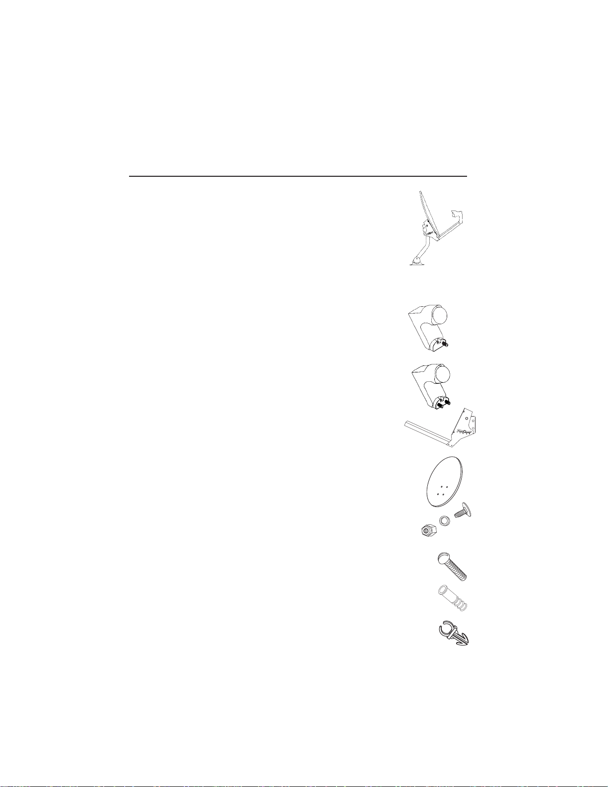
COMPONENTS OF THE SATELLITE ANTENNA
Note: The following pictures are not to scale.
The fully assembled Bell ExpressVu satellite antenna looks like this.
See "Install the Satellite Antenna" on page 1-13 for the procedure to
assemble and install the satellite antenna. Following are descriptions of
each component of the satellite antenna.
DBS LNBF (Low Noise Block amplifier with integrated Feed)
DBS LNBF - Single Output
If you purchased the single-output LNBF to use with one
Bell ExpressVu receiver, your package contains this LNBF.
DBS LNBF - Dual Output
If you purchased the dual output LNBF for use with more
than one Bell ExpressVu receiver, your package contains
this LNBF.
LNBF Support Arm
The LNBF support arm attaches the LNBF and the dish to
the mast assembly. The support arm may come in two pieces
for larger antennas.
Dish
The dish collects and focuses the satellite signal onto the LNBF.
Note: The dish may have either three or four bolt holes.
Flathead bolts with nuts attach the dish to the support arm.
LNBF Screws
The LNBF screw attaches the LNBF to the support arm.
Weather Boot(s)
The rubber boot protects the coaxial cable/LNBF connection from the weather.
Cable Clip (optional)
The cable clip holds the cable to the top of the support arm.
Page 1-2
Installation Guide
Mounting Brackets and Mast Assembly
The mounting bracket and mast assembly attaches the
dish and LNBF assembly to the mounting surface.
If you are planning to use a pole to mount the satellite
antenna, you will not need the mounting bracket and
mast assembly. However, we recommend you keep
them in case you decide to move the satellite antenna.
Optional Installation Kit
The Installation Kit is an optional product that contains the hardware and materials that
you would typically use during various types of installation. To buy the Installation Kit,
contact the location where your Bell ExpressVu system was purchased or call the
Customer Service Call Center at 1-888-SKY-DISH (1-800-759-3474).
The Installation Kit contains the following:
¥ Installation Kit Guide
¥ Installation video tape with step-by-step demonstrations
¥ 7.6-meter telephone cord
¥ Dual telephone adapter
¥ Telephone coupler, for connecting two telephone cords
¥ 2.4-meter triple phono (RCA) Audio/Video cord
¥ Dual grounding block
¥ 9.1-meter Grounding wire, either 8 gauge aluminum or 10 gauge copper
¥ 7.6-meter RG-6 (coaxial) cable with "F" connectors
¥ 30-meter RG-6 (coaxial) cable with "F" connectors
¥ 4 Toggle anchors (3" x 1/4")
¥ 4 Double expansion anchors
¥ 4 Machine bolts (3" x 1/4")
¥ 4 Lag screws (3" x 5/16")
¥ 4 Cable ties
¥ 4 Lag screws (2" x 5/16")
¥ Compass
¥ Silicone sealant
¥ 10 Cable clips for the coaxial cable
If you did not purchase the Installation Kit, but still plan to install your Bell ExpressVu
system yourself, we recommend that you gather the appropriate materials before
beginning installation. Note: Amount of RG-6 (coaxial) cable required will depend on
distance between LNBF and receiver.
The tools you will need to complete the installation will vary, depending on the type of
installation that you do. If you find that you do not have the tools and skills for a certain
procedure, call a professional, such as an Bell ExpressVu dealer or an electrician, for
assistance. These tools are not included in the Installation Kit.
Page 1-3
Installation and Setup
Components of the Satellite Antenna

SUMMARY OF INSTALLATION
Following is a summary of the procedures to install and set up your Bell ExpressVu
system. We recommend that you perform the procedures in the order presented.
1. Unpack the satellite antenna, receiver, and parts (see page 1-6)
and the optional installation kit, if you purchased one (see page 1-3).
2. Review "What You Need to Know" (see page 1-6).
3. Connect the receiver to your TV set, and make sure the Smart Card is installed
(see page 1-8).
4. Determine the approximate location of the Bell ExpressVu satellite
(see page 1-18).
5. Find the best location on your property for the satellite antenna, with a clear line
of sight to the satellite (see pages 1-18 through 1-20).
6. Assemble the satellite antenna and attach it to a solid surface (see pages 1-21
through 1-34).
7. Ground the satellite antenna, and wire it to the Bell ExpressVu receiver
(see pages 1-36).
8. Aim the satellite antenna for the strongest possible signal (see pages 1-38
through 1-42).
9. Connect the receiver to an active telephone connection (see page 1-48). With the
receiver wired to the TV and the antenna properly installed, you will be able to see
the Bell ExpressVu Program Guide, which tells you about available programs,
channels, and services.
10.Order your programming by calling the Bell ExpressVu Customer Service Call Centre
at 1-888-SKY-DISH (see page 1-51).
11.Program the remote control to control the receiver and your other electronic
equipment. This feature is not available on all receiver models. (see page 1-52).
12.Wire the receiver to your audio system, VCR, DVD and other electronic equipment,
as required (see page 1-55).
Page 1-4
Installation Guide
STEP 1: BEFORE YOU START INSTALLATION
T
HE KEY TO SETTING UP YOUR
SYSTEM EASILY – THIS IS
IMPORTANT
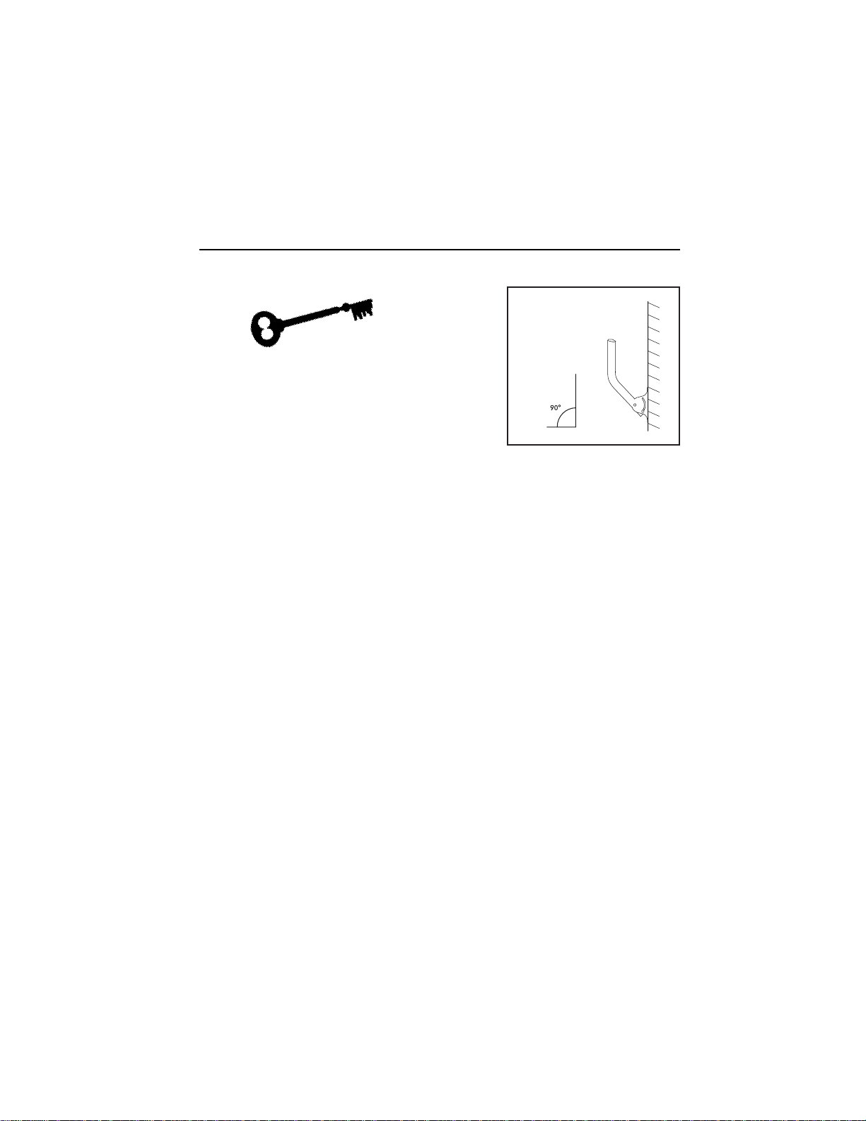
The key to setting up the system is in the accurate initial setting of the vertical elevation
of the dish. The vertical elevation is the amount of tilt upwards, from horizontal, toward
the sky, which is required to ÒseeÓ the satellite. This is best achieved by mounting the
dish support mast so that the top portion, to which the dish clamps attach, is as ÒPlumbÓ
as possible. That is to say: the top portion of the mount should be as perpendicular to the
earth as you can manage - this is true for wall mounting, roof mounting, any kind of
mounting. If it is ÒPlumbÒ, then, when the dish is mounted on it and the dish is tilted
upward toward the satellite at the correct vertical elevation angle, the dish can be easily
panned (East/West movements) to find the satellite.
UNPACK AND CHECK CONTENTS
As you unpack the system, confirm that all the parts are included. See "Package
Contents" on page 1-6 for a list of the included components.
Note: Keep the shipping materials in which these items are packed, in case you ever
need to return them.
Unpack the contents carefully. Electronic equipment can be easily damaged if bumped or
handled roughly. Examine all parts for damage that may have occurred during shipment.
If you find any damage, immediately call the location where your Bell ExpressVu system
was purchased, or the Bell ExpressVu Customer Service Call Centre at
1-888-SKY-DISH, before continuing with installation.
The size of your dish will vary depending on the part of Canada in which you live. The
standard diameter of a Bell ExpressVu dish is 46 cm, however, 60 cm, 90 cm or 1.2m
dishes are also available. If you require the large dish, we recommend that you hire a
professional to install it because installation of the 90 cm and 1.2 m dishes is a more
exacting project.
Page 1-5
Installation and Setup
Before You Start Installation
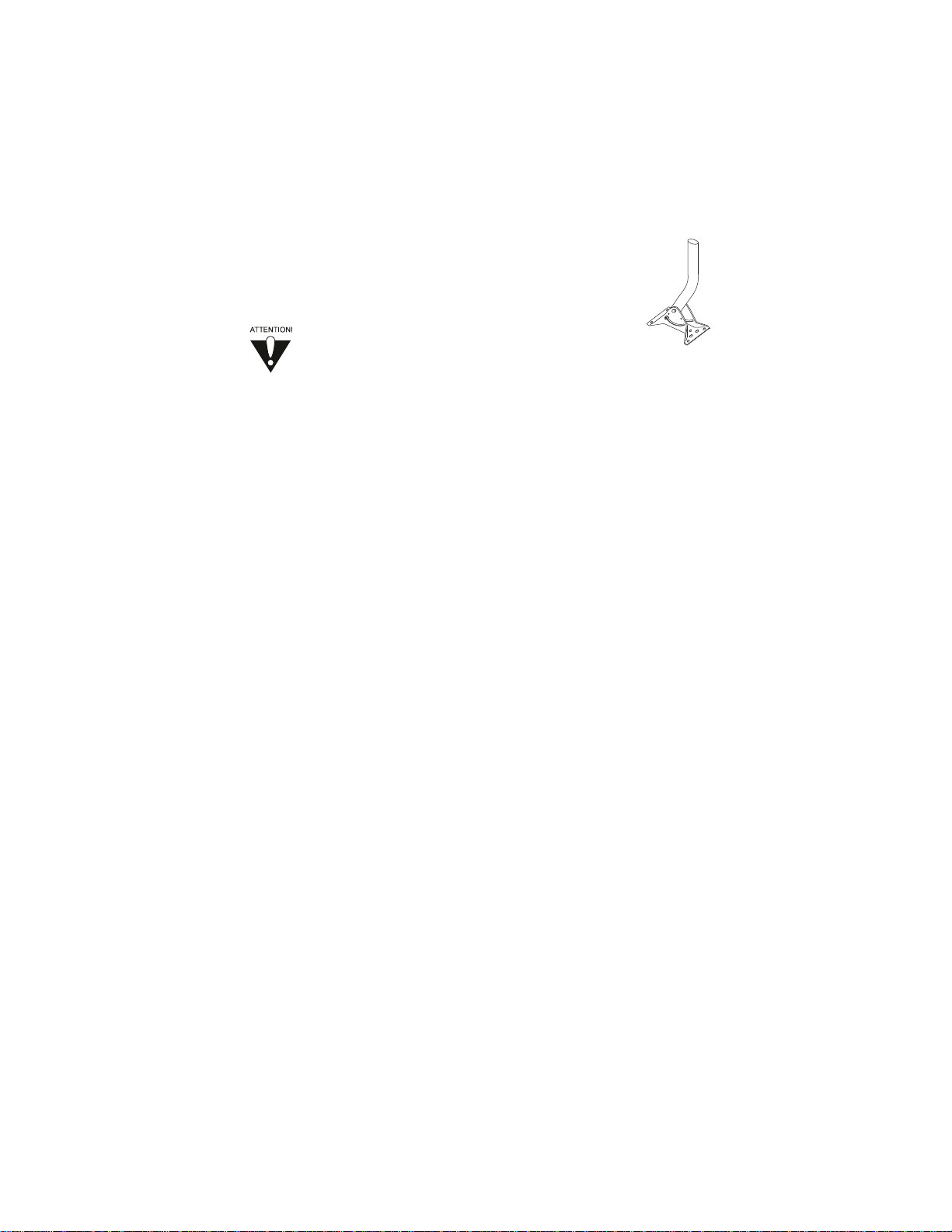
This is a typical
"Mount"shown
attached to a wall.
Notice that the top
portion is "Plumb".
} Top

PACKAGE CONTENTS
¥ User and Installation Guide
¥ Bell ExpressVu satellite antenna assembly
¥ Bell ExpressVu receiver
¥ Accessories
❒ 7.6-metre RJ11 telephone cable
❒ 2.4-metre phono (RCA) 3-connector cable
❒ 1.8-metre modulator cable
❒ 2.4-metre S-VIDEO cable (optional to install) Model 4700 only.
❒ Remote control, with four (4) AAA batteries packaged separately
In addition, we provide an optional Installation Kit, which includes the necessary
hardware and cables that you would typically use during installation. Contact the
location where your Bell ExpressVu system was purchased for more information, or call
the Bell ExpressVu Customer Service Call Centre at 1-888-SKY-DISH for the location of
a licensed dealer near you.
WHAT YOU NEED TO KNOW
Because you will make modifications to the location where you mount the satellite
antenna, we suggest that you be familiar with and be able to safely perform the following
procedures.
¥ You should be able to use a plumb line or level to set both horizontal and vertical
surfaces. This is especially critical for vertical surfaces.
¥ You should know how to drill holes in the mounting surface (whether wood, brick,
cinder block, etc.).
¥ You should know how to drill holes and run cabling through your building. This
includes sealing the holes once the cable has been installed.
WHAT YOU NEED TO HAVE
If you did not purchase the installation kit, you will need the following materials:
¥ Coaxial cables and connectors (RG6 recommended up to 100ft. For longer distances
consult an installer)
¥ Fastening devices to attach the mount to your dwelling
¥ Waterproofing for the outdoor connections
¥ Grounding materials
¥ Cable ties
Page 1-6
Installation Guide
You will also need some tools:
A 7/16Ó,1/2Ó, 9/16Ó wrench (varies with dish size)
A Phillips screwdriver
A spirit level
A drill and drill bits (masonry and wood)
A compass
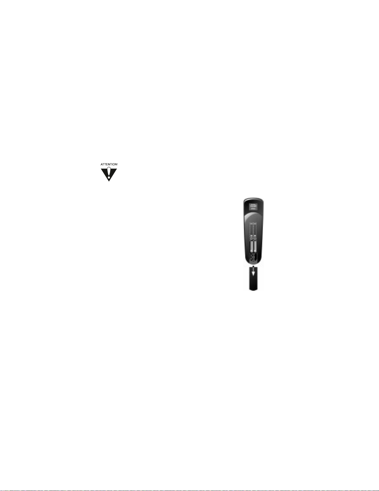
INSTALL BATTERIES IN THE REMOTE
The remote is shipped with four AAA batteries, packaged separately.
Any time you remove or install the batteries, you may have
to reprogram the remote for all electronic components.
1. Press down on the slot in the battery case cover
(on the back of the remote) to open the cover.
2. If you are replacing old batteries, remove all
four batteries.
3. Insert the new batteries, being sure to match the
plus (Ò+Ó) ends with the plus indicators on the
remote. The batteries alternate plus and minus
(Ò-Ó) ends when properly seated.
4. Replace the cover by inserting the tabs into the
slots, and snapping the cover into place.
If the remote does not work after installing the batteries, confirm that the batteries are
properly seated, with the plus and minus ends aligned correctly. You may need to reset
the remote address, particularly if you have a UHF remote.
SET THE REMOTE ADDRESS
When you get your receiver and remote, they are set to address 1. Unless you experience
problems, you do not need to change the address at this time. If you want to change the
address, see ÒSet the Remote AddressÓ on page 1-52.
You may need to set the remote address in any of the following situations:
¥ You have a UHF remote, and you encounter interference caused by other nearby UHF
remotes (for example, a neighbour's UHF remote or a UHF remote being used in
another room of your building).
¥ There is another Bell ExpressVu receiver and remote being used in the vicinity.
Note: In either of the above situations, you may need to assign an address to your
remote and receiver, so that the receiver responds only to that remote.
Page 1-7
Installation and Setup
Before You Start Installation
¥ If your receiver and remote addresses do not match, you must match them to be able to
use the remote. See "Set the Remote Address" on page 1-52.
TEMPORARILY CONNECT THE RECEIVER TO TV
You must connect the receiver to your TV and make sure the Smart Card is installed to
get the information to aim your satellite antenna. At this time, it is not necessary to fully
wire your receiver to all your electronic equipment.
See "Wiring Setups" in your User Manual for suggested wiring configurations.
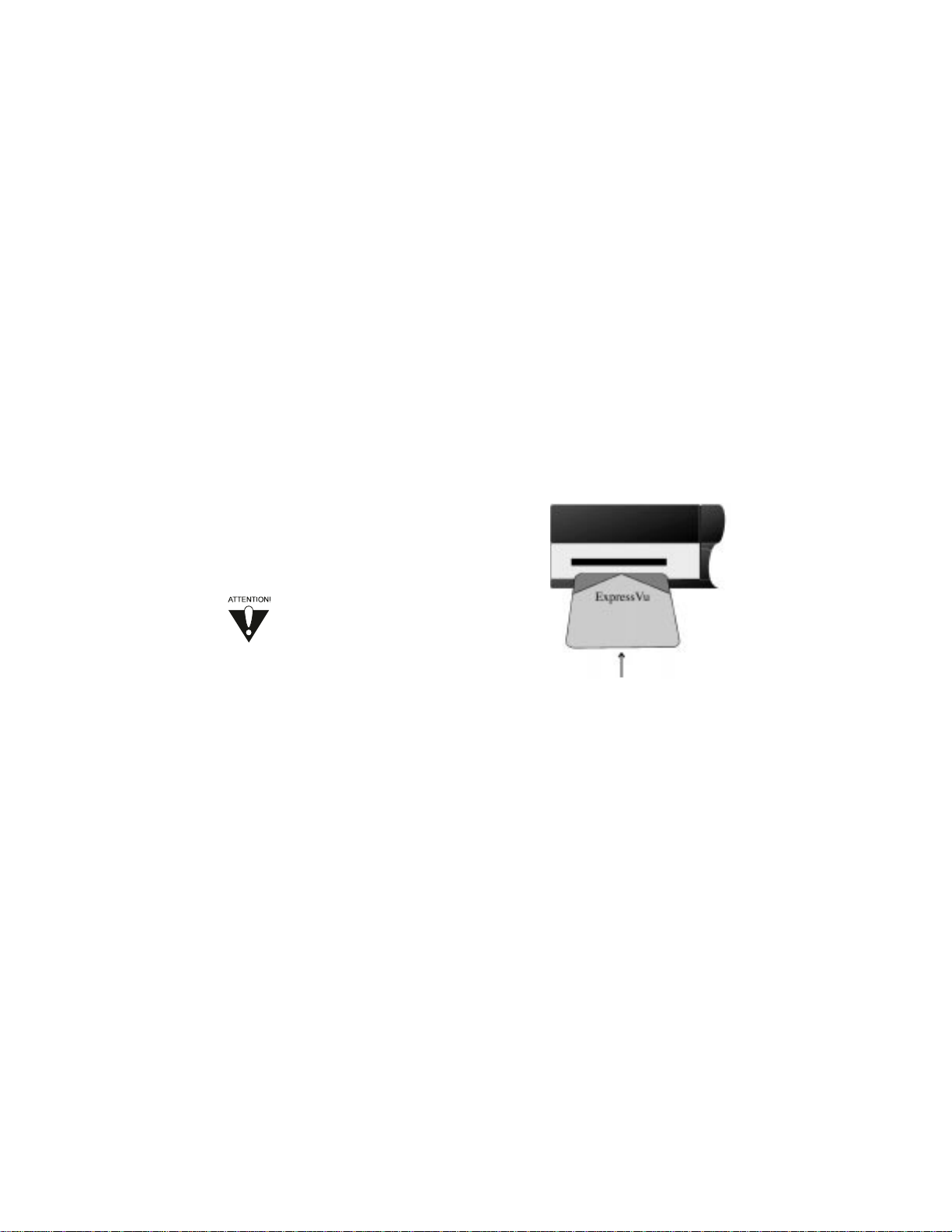
INSTALL THE SMART CARD
Most systems come with the ExpressVu Smart Card
already installed in the receiver. If your Smart Card
came in a separate package, you need to install it
into the Smart Card slot in the receiver.
The receiver will work only with the
Smart Card installed. You must use
the Smart Card that was supplied with
your receiver.
1. Open the access door on the front panel of the
receiver by gently pulling on the left edge.
2. Unwrap the Smart Card, and insert it face up
(face up is logo up).
3. Make sure the Smart Card is firmly seated in the slot.
4. Close the access door.
Note: Model 2700 receivers do not have an access door.
Page 1-8
Installation Guide
Page 1-9
Installation and Setup
Discussion of Potential Mounting Sites
DISCUSSION OF POTENTIAL MOUNTING SITES
When you are surveying your property for appropriate sites for the satellite antenna, keep
in mind that you can mount the satellite antenna on a variety of surfaces: brick, cinder
block, wood, some sidings, rooftop, or a pole.
Because installing the satellite antenna may involve drilling into the wall or roof of your
building, or digging a hole and using cement, you should be confident of the location
before beginning installation. Errors can be expensive and time-consuming.
The following guidelines apply to all mounting surfaces and locations.
WEATHER AND WIND CONSIDERATIONS
The satellite antenna has been built to withstand most kinds of weather. However,
extremely strong winds could damage the base on which the satellite antenna is mounted.
A strong wind can cause the satellite antenna to exert several hundred kilograms of
pressure on the mounting surface, so the surface must be stable and strong. Such a
mounting surface also helps ensure against movement of the satellite antenna, which
would interfere with signal reception. In general, the stronger the signal you maintain,
the better your chance of uninterrupted reception during periods of snow, rain, and heavy
cloud cover.
SOME KEY POINTS TO CONSIDER
DO’S
You should always follow these instructions to help ensure against injury to
yourself and damage to your equipment or building. See "Safety
Instructions" on page i for further safety instructions.
¥ Assemble the satellite antenna in a safe location before climbing up to the mounting
location. Use caution when climbing, and when working at the mounting location.
Depending on the mounting location and size of your dish, 2 people may be required
to install the mount and antenna to your dwelling.
¥ Install the satellite antenna only on a solid surface such as cinderblock, brick, or solid
foundation material. If you install it on the side of a building, be sure to attach the
bolts directly to a building stud or other solid material. Use the appropriate drilling
and attachment hardware for the surface.
¥ Make sure you have determined the best location for the satellite antenna before
drilling the holes in your building or setting up the mounting pole.
Mistakes can be costly.
¥ All installations should conform to your local building and electrical codes. If you are
not sure, contact a licensed building inspector or electrician in your area to assist you.
Be aware that community covenants, if any, may have additional requirements.

¥ If possible choose a site that is accessible in most weather conditions. You may
need to clean snow, ice or debris off the satellite antenna.
¥ Place the satellite antenna as close to the receiver as possible. We recommend using
no more than 30 meters of RG-6 (coaxial) cable between the receiver and the satellite
antenna, unless you install a line amplifier to boost the signal.
¥ Consider seasonal changes. The site may appear unobstructed in the winter, but spring
and summer foliage could block the signal to the satellite antenna.
DO NOTS
¥ Never install the satellite antenna under power lines.
¥ Do not install the satellite antenna where it can be jostled, bumped, or blocked by
people, animals, or vehicles.
¥ Do not install the satellite antenna where it is exposed to high winds.
¥ Do not try to install the satellite antenna in windy or stormy weather, particularly if
there is a chance of lightning.
¥ Do not attempt to fasten the satellite antenna to the mortar between bricks or cinder
blocks.
¥ Do not mount the satellite antenna on vinyl or aluminum siding. These materials are
structurally too weak to securely hold the satellite antenna, even with a building stud
underneath.
¥ Do not install the satellite antenna on stucco or imitation masonry unless the base
material is solid. Do not mount the satellite antenna on composite materials such as
strand, chip, fiber, or particle board unless the fastener attaches securely to a wall stud,
rafter, or other foundation material beneath the surface.
underneath.
¥ Do not mount the satellite antenna in a tree.
Page 1-10
Installation Guide
Page 1-11
Installation and Setup
Discussion of Potential Mounting Sites
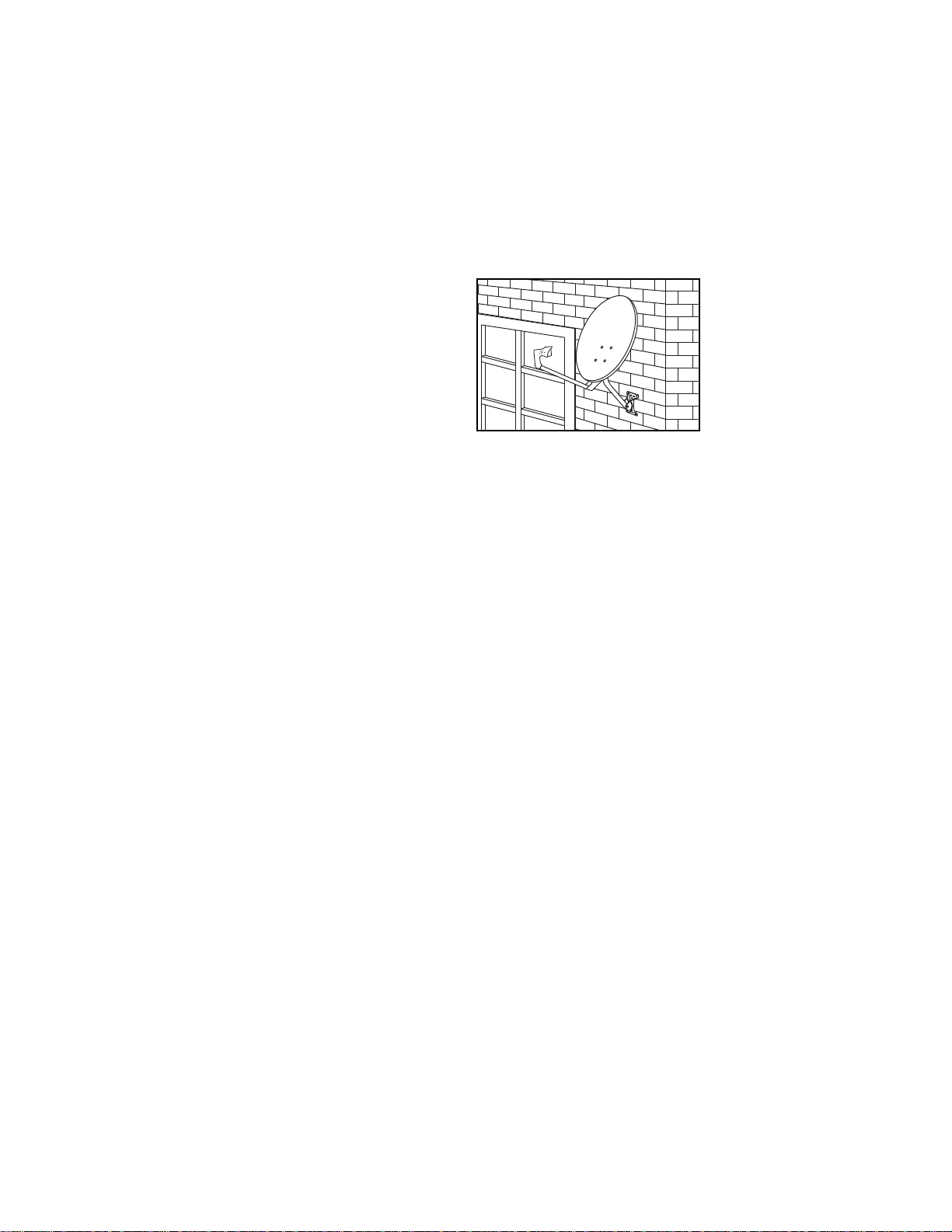
MOUNTING THE ANTENNA ON BRICK
We define "brick" as a solid brick wall
or other structure. This does not include
brick facing that is used on some
buildings over the main structure. If you
are mounting the satellite antenna on
brick facing, see "Mounting the Antenna
on Siding," below.
You can mount the satellite antenna on a
solid brick wall.
¥ The brick surface must be flat and even.
¥ The mortar between the bricks should be in good to excellent condition. The satellite
antenna foot should be mounted on several bricks. As the wind tugs on the satellite
antenna, the foot will put heavy pressure (several hundred kilograms) on those bricks
in different directions. Loose or weakened mortar may allow the bricks to shift,
changing the dish angle and reception quality, and possibly damaging the satellite
antenna and the building. The installed satellite antenna could also hasten the
deterioration of old mortar.
¥ To mount the satellite antenna on brick, be sure that all of the fasteners are set into the
brick, not into the mortar between the bricks. Use materials necessary to follow the
local building codes.
MOUNTING THE ANTENNA ON SIDING
We do not recommend mounting the satellite antenna on aluminum or vinyl siding.
These materials can be structurally unsound, causing eventual shifting of the dish. To
mount the satellite antenna on solid siding, be sure to follow the suggestions below.
¥ The surface must be flat and even. You may need to use a separator, or shim, between
the shingles to even the siding surface.
¥ Mount the foot on the foundation material beneath the siding surface. This may be a
building stud, cinder block, or other solid material. To locate the studs, find the
vertical line of nails where the siding is attached to the building, or use a stud finder.
MOUNTING THE ANTENNA ON CINDER BLOCK
You can mount the satellite antenna on cinder
blocks, whether they are part of a wall or the side
of a building.
¥ The surface must be flat and even.
¥ Be sure that the cinder block and mortar are in good condition.
¥ We recommend using toggle anchors and machine bolts, inserted into the hollow of the
block, as fasteners. Other types of anchors may not have the required strength.
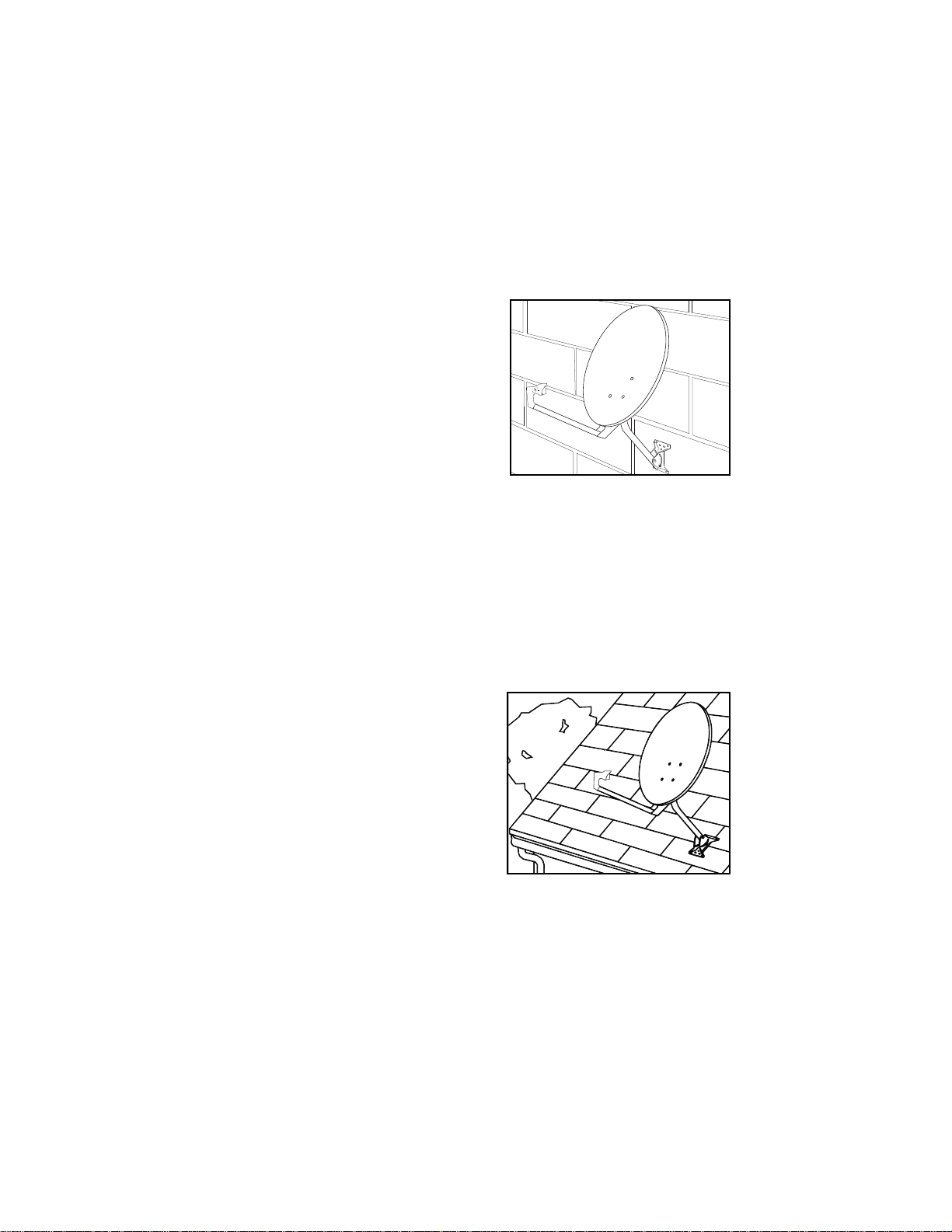
MOUNTING THE ANTENNA ON THE ROOF
You can mount the satellite antenna on the roof.
This usually provides the highest available
location.
¥ Attach the satellite antenna to a rafter beneath the roof surface. You can locate the
rafter by looking for the nails attaching the fascia board to the rafters. You can also
locate the rafters from inside the attic.
¥ To prevent the roof from leaking, you should caulk the holes, or use silicone sealant
around the holes and at the bottom of the satellite antenna foot where it contacts the
surface. Apply the sealant before you bolt the foot down tight.
Page 1-12
Installation Guide
Page 1-13
Installation and Setup
Discussion of Potential Mounting Sites
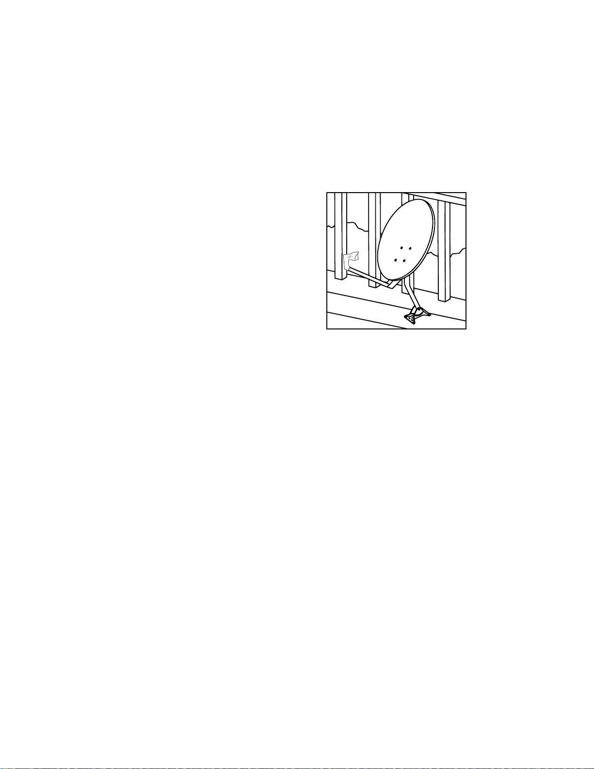
MOUNTING THE ANTENNA ON WOOD
You can mount the satellite antenna on a
wooden deck, wooden beam, or other
wooden surface.
¥ The surface must be flat and even.
¥ Be sure that the wood has a solid foundation, and is secured. It should be a strong
piece that cannot be moved or jiggled.
¥ Do not mount the satellite antenna on a railing.
INSTALL THE SATELLITE ANTENNA
Once you have found the direction and elevation of the satellite and decided on the best
mounting location, you can install the satellite antenna.
ORIENTATION OF MAST OR POLE
It is very important that the upper part of the mast or the mounting pole,
whichever is used, be truly plumb (vertical). If not, the elevation provided by the
receiver for your location will be inaccurate. This will make it more difficult for you to
find the satellite.
Refer to page 1-4, ÒSummary of InstallationÓ to begin the installation of your antenna.
Page 1-14
Installation Guide
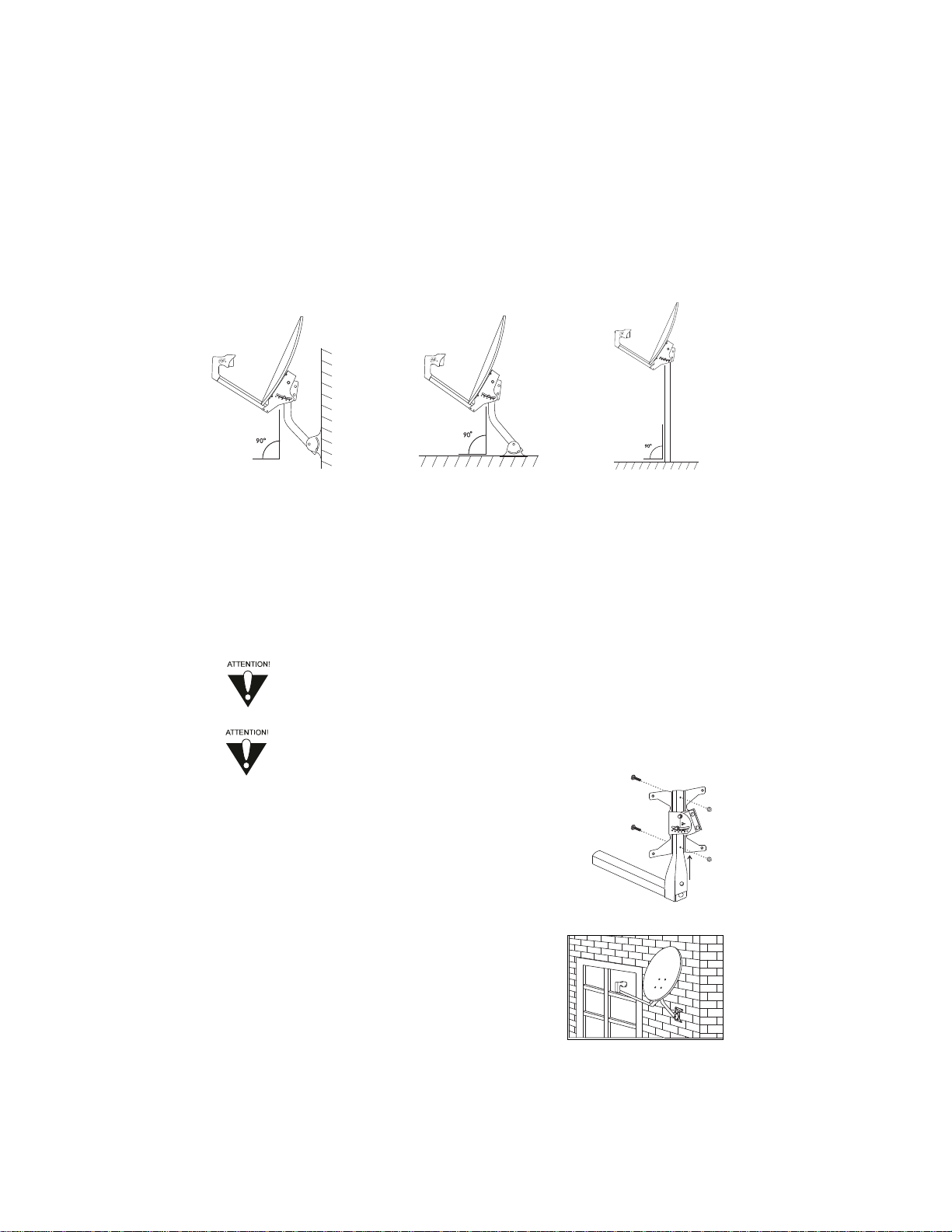
Vertical Mounting Horizontal Mounting Pole Mounting
Surfaces with Mast Surfaces with Mast Surfaces
Install the Antenna Mount
Before you install the antenna mount, you should make sure that you can
route the cable from the mounting location into your building, drilling holes
where necessary, to the receiver.
Assemble the satellite antenna in a safe location before climbing up to the
mounting location. Use caution when climbing, and when working at the
mounting location.
1. Gather all the items you will need for the assembly.
2. If the dish support arm and the bracket that holds it came
separately, attach the arm to the bracket with the
supplied bolts.
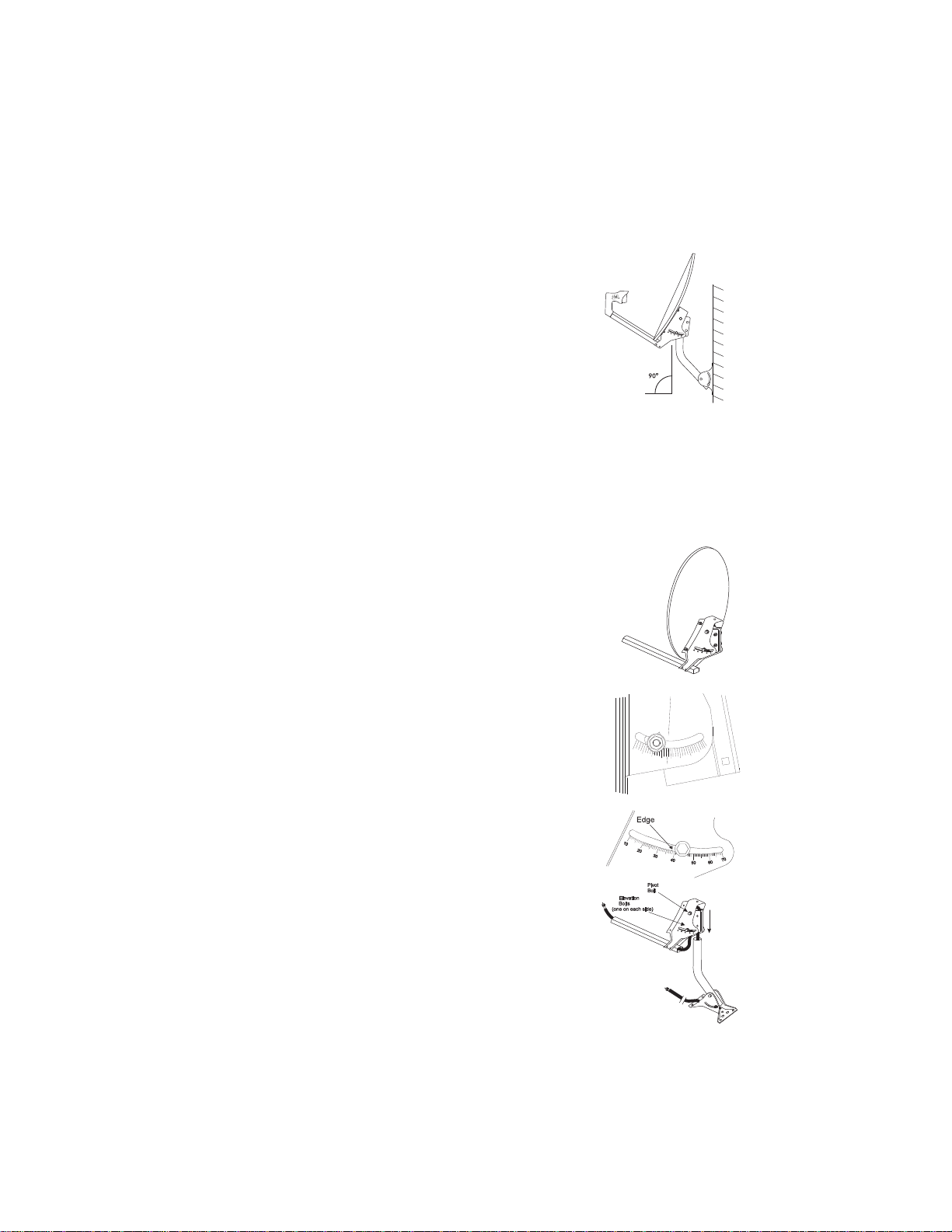
3. Mount the foot on the solid surface you have chosen.
4. Adjust the mast so that when the foot is mounted, the
upper part of the mast is, as close to vertical as possible.
Use a plumb line or bubble level to measure the upper
part of the mast. Alignment of the dish is more difficult
if the mast is not plumb.
The figure above
shows how you
should attach the
mast to the foot for
mounting on vertical
surfaces.
The figure above
shows how you
should attach the
mast to the foot for
mounting on
horizontal surfaces.
The figure above
shows how you
should attach the
dish support and
bracket to a
mounting pole.
You may have either one or two LNBF cables to attach,
depending on which type of LNBF you purchased and how
many receivers are being installed.
Note: If you have to attach two cables to the LNBF,
the following instructions apply to both cables. Use
only RG-6 coaxial cables with "F" connectors. Do
not use the 1.8-meter RF or VHF cable supplied with
the receiver. This cable is used for the receiver to
TV connection.
5. Place the dish on the support arm. Align the
flathead bolts with the dish support bolt holes
on the dish supports.
6. Insert each flathead bolt into one of the holes, and
secure it by threading a lock nut onto the bolt on
the back side. Do this for all the flathead bolts.
7. Tighten the bolts so that they are snug.
This is a picture of the support arm and bracket
with the dish attached.
8. Tilt the support bracket to the approximate elevation
of the satellite. Use the elevation you found earlier
on the Satellite Location Reference Chart.
If you have the bracket with points above the
elevation washer, align the elevation marks on the
bracket with the points on the washer.
If you have the bracket where the edge of the mast
shows through the curved slot, align the edge with
the desired elevation mark.
9. Slide the mast clamp onto the mast.
Tighten the elevation bolts and the pivot bolt so that
the bracket is snug, but can still be moved up and down.
10.Turn the antenna mount on the mast or pole to align
the LNBF support arm in the direction of the satellite.
Use the direction you found earlier in the Satellite
Location Reference Chart.
Page 1-15
Installation and Setup
Discussion of Potential Mounting Sites
60
10
20
50
30
40
60
CM
46
70
80
90
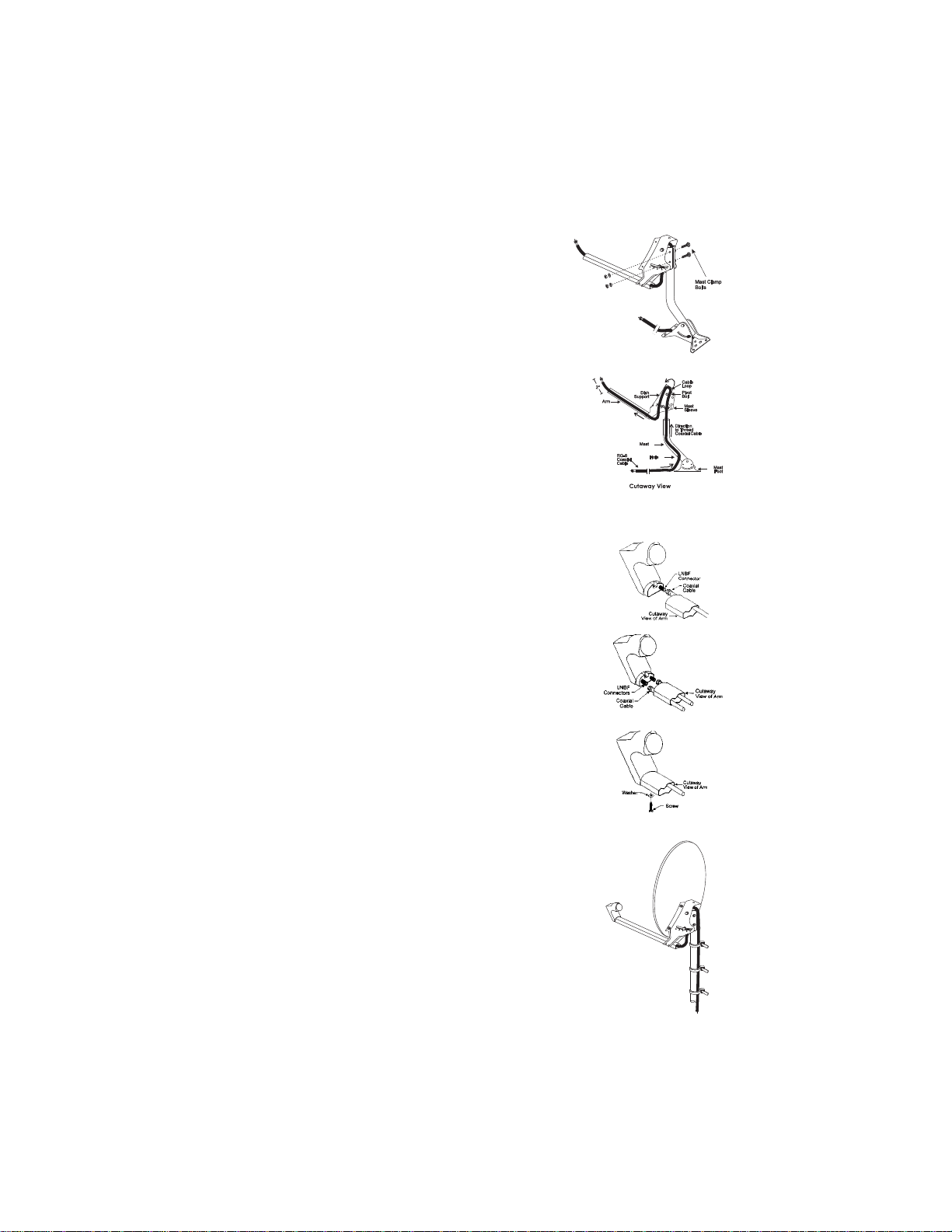
Tighten the mast clamp bolts so that the clamp is snug,
but can still be moved back and forth.
11. Thread the LNBF cable into the cable hole near
the mast foot, up the mast and out the top of the mast.
Do not kink or pinch the cable.
12. Take the end of the cable coming out the top of the
mast, and thread it up the mast sleeve of the support arm.
13. Loop the end of the cable over the pivot bolt.
14. Bring the cable back down on the outside of the
mast sleeve, between the dish supports.
15. Thread the cable through the arm and out the end of the arm.
16. Slip the weather boot(s) onto the LNBF cable(s).
To do this, insert the end of the cable with the screw
connector into the smaller end of the boot and work
it through. When you are finished the boot should slide
freely over the cable but hold snugly when slipped up
over the screw connector. Be patient. This is a difficult
and somewhat painstaking job. (If possible, place
weather boot on cable before putting on "F" connector).
17. Attach the LNBF to the LNBF cable(s). Slide the
weather boot up securely to cover the cable/LNBF
connection at the base of the LNBF.
18. Fit the LNBF onto the end of the dish support arm, sliding
it until it is inserted firmly. Attach LNBF to the support arm
using the LNBF screw and washer.
INSTALLING A METAL POLE MOUNT
You can mount the satellite antenna on a metal pole if
necessary. This allows you a wider range of locations for
installation.
Note: If used, the metal pole should have an outside diameter
of approximately 1 5/8 inches (approx. 4 cm), and should be
sturdy enough not to flex in high winds. If the clamp ends up
being slightly loose, use weather proof sandpaper or emery
cloth to shim the clamp, and tighten.
Page 1-16
Installation Guide
 Loading...