

Belle Minitile 180, Minitile 200, Minitile 230, Magiktile 180, Maxitile 260 Operator's Manual [en, fr, es]
Page 1
1
- Spare Parts Book
- Pièces détachées
- Libro Despiece
Operators Manual
Operators Manual
Manuel De L'Opérateur
Manual del Operador
GB
F
E
US
4
12
20
28
36
870/30006/0
Page 2
2
Signed by: Managing Director - On behalf of BELLE GROUP (SHEEN) UK.
Signature: Le Directeur Général - Pour le compte de la SOCIETE BELLE GROUP (SHEEN) UK.
Medido por: Director Gerente - En nombre de BELLE GROUP (SHEEN) UK.
Assinado por: Director-Geral - Em nome de BELLE GROUP (SHEEN) UK.
Getekend door: Algemeen Directeur - Namens BELLE GROUP (SHEEN) UK.
Uunderskrevetaf: Administrerende direktør – På vegne af BELLE GROUP (SHEEN) UK.
PRODUCT TYPE ................. TYPE DE PRODUIT.............. TIPO DE PRODUCTO.......... TIPO DE PRODUCTO .........
MODEL................................. MODELE............................... MODELO .............................. MODELO..............................
SERIAL No........................... N° DE SERIE ........................ N° DE SERIE........................ NO. DE SÉRIE .....................
DATE OF MANUFACTURE. DATE DE FABRICATION..... FECHA DE FABRICACIÓN.. DATA DE FABRIC
SOUND POWER LEVEL NIVEAU DE PUISSANCE NIVEL DE POTENCIA NIVEL DE POTÊNCIA
MEASURED......................... SONORE MESUREE............ ACÚSTICA MEDIDO............ DE SOM MEDIDO................
(GUARANTEED).................. (GARANTIE)......................... (GARANTIZADO)................. (GARANTIDO) .....................
WEIGHT............................... POIDS................................... PESO.................................... PESO ...................................
We, Belle Group Sheen UK, Sheen, Nr. Buxton, Derbyshire, SK17 0EU, GB, hereby certify that if the product described within this certificate is bought from an
authorised Belle Group dealer within the EEC, it conforms to the following EEC directives: 98/37/EC (This directive is a consolidation of the original machinery directive
89/392/EEC), Electromagnetic Compatibility Directive 89/336/EEC (as amended by 92/31/EEC & 93/68 EEC). The low voltage directive 73/23/EEC, BS EN ISO
12100-1:2003 Safety of machinery and associated harmonised standards, where applicable. Noise emissions conform to directive 2000/14/EC Annex VI, for machines
under article 12 the notified body is AV Technology Limited, AVTECH house, Birdhall Lane, Cheadle Heath, Stockport, Cheshire, SK3 0XU, GB.
Noise Technical Files are held at the Belle Group Head Office address which is stated above.
Nous soussignons, Belle Group Sheen UK, Sheen, Nr Buxton, Derbyshire, SK17 0EU, GB, certifions que si le produit décrit dans ce certificat est acheté chez un
distributeur autorisé Belle Group au sein de la CEE, il est conforme aux normes CEE ci-après: 98/37/CE (Cette norme est une codification des normes de la machine
d'origine 89/392/CEE), Norme compatible pour l'électromagnisme 89/336/CEE (modifié par 92/31/CEE et 93/68/CEE). Caractéristiques basse tension 73/23/CEE, BS EN
ISO 12100-1:2003, Norme de sécurité des machines et des critères associés et configurés, si applicable. Les émissions de bruit sont conformes à la directive
2000/14/EC Annexe VI pour machines , article 12, l’objet mentionné est AV Technology Mimited, AVTECH House, Birhall Lane, Cheadle Heath, Stockport, Cheshire,
SK3 0XU, GB.
Les dossiers techniques sur les émissions sonores des machines sont détenus au siège social de BELLE GROUP à l’adresse ci-dessus.
La Sociedad, Belle Group Sheen UK, Sheen, Nr. Buxton, Derbyshire, SK 17 OEU, GB, por el presente documento certifica que si el producto descrito en este
certificado es comprado a un distribuidor autorizado de Belle Group en la CEE, este es conforme a las siguientes directivas: 98/37/CE de la CEE (Esta directiva
consolida la directiva inicial sobre maquinaria 89/392/CEE), Directiva 89/336 CEE sobre Compatibilidad Electromagnética (según enmiendas 92/31/CEE y 93/68 CEE),
Directiva sobre Bajo Voltaje 73/23/CEE, BS EN ISO 12100-1:2003 de Seguridad de Maquinaria y Niveles armonizados estándares asociados donde sean aplicables.
Emisión de Ruídos conforme a la Directiva 2000/14/CE Anexo VI para máquinas bajo artículo 12 la mencionada unidad está AV Technology Limited, AVTECH House,
Birdhall Lane, Cheadle Heath, Stockport, Cheshire, SK3 OXU, GB.
En La Sede Central de Belle Group existen Archivos Técnicos con contenido referente a Niveles de Ruido.
O signatário, Belle Group Sheen UK, Sheen, Nr Buxton, Derbyshire, SK 0EU, GB, pelo presente, declara que se o produto descrito neste certificado foi adquirido a
um distribuidor autorizado do Belle Group em qualquer país da UE, está em conformidade com o estabelecido nas seguintes directivas comunitárias: 98/37/EC (esta
directiva é uma consolidação da directiva de maquinaria original 89/392/EEC), Directiva de Compatibilidade Electromagnética 89/336/EEC (conforme corrigido pelas
92/31/EEC & 93/68 EEC). A directiva de baixa voltagem 73/23/EEC, BS EN ISO 12100-1:2003 Segurança da maquinaria e às normas harmonizadas afins se aplicáveis.
As emissões de ruído respeitam e estão dentro das directivas para máquinas 2000/14/EC Anexo VI, artigo 12, sendo o organismo notificado AV Technology Limited,
AVTECH house, Birdhall Lane, Cheadle Heath, Stockport, Cheshire, SK3 0XU, GB.
A informação técnica sobre níveis sonoros está disponivel na Sede da Belle Group na morada acima mencionada.
Ondergetekende, Belle Group Sheen UK, Sheen, Nr. Buxton, Derbyshire, SK17 OEU, GB, verklaren hierbij dat als het product zoals beschreven in dit certificaat is
gekocht van een erkende Belle Group dealer binnen de EEG, het voldoet aan de volgende EEG richtlijnen: 98/37/EC (Deze richtlijn is een opvolger van de orginele
Machinerichtlijn 89/392/EEG), Electromagnetische Compatability Richtlijn 89/336/EEG ( geamendeerd door 92/31/EEG & 93/68 EEG). De Laagspannings Richtlijn
72/23/EEG, BS EN ISO 12100-1:2003 Veiligheid van Machines en hieraan gekoppelde geharmoniseerde Standaarden, waar deze van toepassing is. Rumoer emissions
passen voor richtlijn EC Zijgebouw VI , voor toestel onder stuk 12 naar de notified troep zit AV Technology Limited, AVTECH house, Birdhall Lane, Cheadle Heath,
Stockport, Cheshire, SK3 OXU, GB
Worden de Technische Dossiers van het lawaai gehouden op het adres van het Hoofdkantoor van de Groep Belle dat hierboven ' wordt verklaard.
Vi, Belle Group Sheen UK, Sheen, Nr. Buxton, Derbyshire, SK17 0EU, GB, erklærer hermed, at hvis det i dette certifikat beskrevne produkt er købt hos en autoriseret
Belle Group forhandler i EU, er det i overensstemmelse med følgende EØF-direktiver: 98/37/EF, 73/23/EØF (som ændret ved 93/68/EØF), 89/336/EØF (som ændret ved
92/31/EØF), 93/68/EØF og tilknyttede, harmoniserede standarder, hvor relevant. Støjniveauet er i overensstemmelse med direktiv 2000/14/EF, bilag VI gældende for
maskiner under paragraf 12. Det bemyndigede organ er AV Technology Limited, AVTECH house, Birdhall Lane, Cheadle Heath, Stockport, Cheshire, SK3 0XU,
Storbritanien.
EC DECLARATION OF CONFORMITY / DECLARATION CE DE CONFORMITE /
DECLARACIÓN DE CONFORMIDAD CE / DECLARAÇÃO CE DE CONFORMIDADE /
EG-VERKLARING VAN OVEREENSTEMMING / EF
OVERENSSTEMMELSESERKLÆRING
Ray Neilson
PRODUCTTYPE .................. PRODUKTTYPE...................
MODEL................................. MODEL .................................
SERIENUMMER................... SERIENR. .............................
FABRICAGEDATUM............ FREMSTILLINGSDATO.......
GEMETEN LYDEFFEKTNIVEAU
GELUIDSSTERKTENIVEAU MÅLT....................................
(GEGARANDEERD) ............ (GARANTERET)...................
GEWICHT............................. VÆGT...................................
GB
F
E
P
NL
DK
Page 3
3
Unterzeichnet vo: Generaldirektor – Im auftrag von BELLE GROUP (SHEEN) UK.
Firmato da: Amministratore Delegato – Per conto di BELLE GROUP (SHEEN) UK.
Undertecknat: V.D. – På vägnar av BELLE GROUP (SHEEN) UK.
Signatur: Managing Director - På vegne av SOCIETE BELLE GROUP (SHEEN) UK.
Allekirjoitus: Toimitusjohtaja - BELLE GROUP (SHEEN) UK: n puolesta.
Podpisa³: Dyrektor Zarządzający – w imieniu BELLE GROUP (SHEEN) UK
PRODUKTTYP..................... TIPO PRODOTTO ................ PRODUKTTYP..................... PRODUKTTYP.....................
MODELL .............................. MODELLO ............................ MODELL............................... MODELL ..............................
SERIENNR........................... SERIE N° .............................. SERIE NR. ........................... SERIE NR. ..........................
HERSTELLUNGSDATU ...... DATA DI FABBRICAZIONE.. TILLVERKNINGSDATUM..... PRODUKSJONSDATO........
SCHALLLEISTUNGSPEGEL LIVELLO POTENZA LJUDSTYRKA LYDKRAFTNIVÅ
GEMESSEN......................... SONORA MISURATA........... UPPMÄTT............................. MÅLT ...................................
(GARANTIERT).................... (GARANTITA)....................... (GARANTERAD).................. (GARANTERT) ....................
GEWICHT............................. PESO .................................... VIKT...................................... VEKT....................................
Wir, Belle Group Sheen UK, Sheen, Nr. Buxton, Derbyshire, SK17 0EU, Großbritannien, bestätigen hiermit, dass das in diesem Zertifikat beschriebene Produkt,
wenn es von einem autorisierten Belle Group Händler innerhalb der europäischen Gemeinschaft gekauft wurde, folgenden EG-Richtlinien entspricht: 98/37/EG, 73/23/EG
(geändert durch 93/68/EG), 89/336/EG (geändert durch 92/31/EG), 93/68/EG und, wenn zutreffend, den harmonisierten Normen. Geräuschemissionen entsprechen der
Richtlinie 2000/14/EG, Anhang VI, für Maschinen unter Artikel 12: die benannte Stelle ist AV Technology Limited, AVTECH House, Birdhall Lane, Cheadle Heath,
Stockport, Cheshire, SK3 0XU, GB.
Geräuschtechnische Dokumente stehen in unserer Zentrale unter obig angegebener Adresse zur Verfügung.
Il Gruppo Belle Sheen UK, Sheen, Nr. Buxton, Derbyshire, SK17 0EU, GB, certifica che il prodotto descritto nel presente certificato è acquistato da un concessionario
autorizzato del gruppo Belle nell'ambito CEE e che è pienamente conforme alle seguenti direttive CEE: 98/37/EC, 73/23/EEC (emendamento 93/68/CEE), 89/336/EEC
(emendamento 92/31/CEE), 93/68/CEE e relativi standard armonizzati. Livelli acustici sono in conformità con la direttiva 2000/14/EC Annex VI per macchine coperte dall’
articolo 12. L’ente di riferimento è AV Technology Limited, AVTECH house, Birdhall Lane, Cheadle Heath, Stockport, Cheshire, SK3 0XU, GB.
Dati tecnici relativi ai livelli acustici sono disponibili su richiesta dalla sede madre Belle Group al sopra citato indirizzo.
Undertecknade, Belle Group Sheen UK, Sheen, Nr Buxton, Derbyshire, SK17 0EU, Storbritannien, intygar härmed att en produkt beskriven i detta certifikat som
köps från en godkänd Belle Group återförsäljare inom EU stämmer överens med följande EG-direktiv: 98/37/EG, 73/23/EG (ändrat genom 93/68/EEC), 89/336/EG
(ändrat genom 92/31/EG), 93/68/EG och tillhörande harmoniserade standarder i tillämpliga fall. Buller nivån överensstämmer med Direktiv 2000/14/EC Bilaga VI gällande
maskiner under artikel 12, den aviserade organisationen är AV Technology Limited, AVTECH house, Birdhall Lane, Cheadle Heath, Stockport, Cheshire, SK3 0XU,
Storbritannien.
Teknisk dokumentation vad gäller test av maskiners ljud/bullernivå finns dokumenterad hos Belle-Groups huvudkontor i Sheen, England.
Vi, Belle Group Sheen UK, Sheen, Nr Buxton, Derbyshire, SK17 0EU, GB, bekrefter med dette at det produktet som står beskrevet i denne erklæringen er kjøpt fra en
autorisert Belle Group forhandler innen EØF, og at det oppfyller følgende direktiver: 98/37/CE dette direktivet er et sammendrag av det opprinnelige maskindirektivet
89/392/EØF), Det elektromagnetisk kompatabiltets-direktivet 89/336/EØF (som endret av 92/31/EØF og 93/68/EØF). Lavspenningsdirektivet 73/23/EØF, BS EN ISO
12100-1:2003, Sikkerhet til maskineri og tilhørende harmoniserte standarder, hvor atuelt. Støyemisjon er i samsvar med direktiv 2000/14/EC, vedlegg VI, for maskiner.
Organet som skal informeres under artikkel 12 er
AV Technology Limited, AVTECH House, Birhall Lane, Cheadle Heath, Stockport, Cheshire, SK3 0XU, GB.
Lydtekniske filer er arkivert hos Bell Group Hovedkontor med adresse som nevnt ovenfor.
Me, Belle Group Sheen UK, Sheen, Nr. Buxton, Derbyshire, SK17 0EU, GB, ilmoitamme täten, että jos tässä todistuksessa kuvattu tuote on ostettu valtuutetulta Belle
Groupin myyjältä ETY:n alueella, se on yhdenmukainen seuraavien ETY-direktiivien kanssa: 98(37/EY (Tämä direktiivi on yhdistelmä alkuperäisestä konedirektiivistä
89/392/ETY, sähkömagneettisen yhteensopivuuden direktiivistä 89/336/ETY, korjauksineen 92/31/ETY ja 93/68/ETY), matalajännitedirektiivistä 73/23/ETY,
koneturvallisuusstandardista BS EN ISO 12100-1:2003 ja siihen liittyvistä yhdenmukaistetuista standardeista, tapauksen mukaan. Melumittaus mittaus on laadittu
direktiivin 2000/14/EC Kohdan VI artiklan 12 mukaisille koneille mukaan. Mittauksen suorittaja on AV Technology Limited, AVTECH House, Birdhall Lane, Cheadle
Heath, Stockport, Cheshire, SK3 0XU, GB.
Melumittausten teknilliset arvot ovat saatavana Belle Group pääkonttorin ylläolevasta osoitteesta.
My, Belle Group Sheen UK, Sheen, Nr. Buxton, Derbyshire, SK17 0EU, Wielka Brytania, niniejszym poświadczamy, iż produkt opisany w tym świadectwie został
zakupiony od autoryzowanej Belle Group w UE i jest zgodny z następującymi dyrektywami EU: 98/37/EC (ta dyrektywa to konsolidacja oryginalnej dyrektywy na temat
maszyn 89/392/EEC), Dyrektywą zgodności elektromagnetycznej 89/336/EEC (z poprawkami wniesionymi przez 92/31/EEC oraz 93/68/EEC), Dyrektywą w sprawie
niskich napięć 73/23/EEC, BS EN ISO 12100-1:2003 Bezpieczeństwo maszyn i związane normy harmonizacyjne, tam gdzie to ma zastosowanie. Poziom hałasu jest
zgodny z Dyrektywą 2000/14/EC Zalącznik VI, organizacja zawiadamiana (odnośnie zgodności) to AV Technology Limited, AVTECH house, Birdhall Lane, Cheadle
Heath, Stockport, Cheshire, SK3 0XU, Wielka Brytania.
Informacje Techniczne dotyczące poziomu hałasu są przechowywane w Belle Group – adres powyżej.
EGKONFORMITÄTSERKLÄRUNG / DICHIARAZIONE CE DI CONFORMITÁ /
EG-VERKLARING VAN OVEREENSTEMMING /
EC SAMSVARSERKLÆRING / EY-YHDENMUKAISUUSILMOITUS / DEKLARACJA
ZGODNOSCI Z PRZEPISAMI UE
Ray Neilson
TUOTETYYPPI..................... TYP PRODUKTO..................
MALLI................................... MODEL .................................
VALMISTUSNRO................. Nr SERII................................
VALMISTUSPÄIVÄ.............. DATAPRODUKCJI ...............
ÄÄNENVOIMAKKUUDEN POZIOM MOCY
TASO MITATTU...................
DŹWIĘ
KU ZMIERZONY ......
(TAATTU) ............................. (GWARANTOWANY)............
MASSA................................. WAGA ...................................
D
I
S
NO
SF
PL
Page 4
4
How To Use This Manual
GB
This manual has been written to help you operate and service the Tile Saw safely. This manual is intended for dealers and operators of
the Tile Saw.
Foreword
The ‘Environment’ section gives instructions on how to handle the recycling of discarded apparatus in an environmentally friendly way.
The ‘General Safety’ and ‘Health and Safety’ sections explain how to use the machine to ensure your safety and the safety of the
general public.
The ‘Trouble Shooting’ guide helps you if you have a problem with your machine.
The ‘Service & Maintenance’ section is to help you with the general maintenance and servicing of your machine.
The ‘Warranty’ Section details the nature of the warranty cover and the claims procedure.
The ‘Declaration of Conformity’ section shows the standards that the machine has been built to.
Directives with regard to the notations.
Text in this manual to which special attention must be paid are shown in the following way:
The product can be at risk. The machine or yourself can be damaged or injured if procedures are not
carried out in the correct way.
CAUTION
The life of the operator can be at risk.
WARNING
WARNING
GB
Before you operate or carry out any maintenance on this machine YOU MUST READ and STUDY
this manual.
WARNING
Contents
KNOW how to safely use the unit’s controls and what you must do for safe maintenance. (NB Be sure that you know how to switch the
machine off before you switch on, in case you get into diffi culty.)
ALWAYS wear or use the proper safety items required for your personal protection. If you have ANY QUESTIONS about the safe use
or maintenance of this unit, ASK YOUR SUPERVISOR OR CONTACT: BELLE GROUP (UK): +44 (0) 1298 84606
GB
How to use this manual ............................................................................................................................................................................. 4
Warning ...................................................................................................................................................................................................... 4
Technical Data ............................................................................................................................................................................................ 5
Environment ............................................................................................................................................................................................... 5
General Safety ........................................................................................................................................................................................... 6
Health & Safety .......................................................................................................................................................................................... 7
Connecting to the Power Supply ............................................................................................................................................................... 7
Pre-Start Checks ........................................................................................................................................................................................ 7
Adjusting the Blade Guard .........................................................................................................................................................................8
Installation .................................................................................................................................................................................................. 8
Transportation ............................................................................................................................................................................................ 8
Operating Instructions ................................................................................................................................................................................9
Service & Maintenance ............................................................................................................................................................................ 10
Trouble Shooting Guide ............................................................................................................................................................................11
Warranty ....................................................................................................................................................................................................11
Declaration of Conformity .......................................................................................................................................................................... 2
Belle Group reserves the right to change machine specifi cation without prior notice or obligation.
Page 5
5
Technical Data
GB
Environment
GB
Safe Disposal.
Instructions for the protection of the
environment. The machine contains valuable
materials. Take the discarded apparatus and
accessories to the relevant recycling facilities.
Component Material
Electric Motor Aluminium
Steel
Copper
Polyamide
Main Body Steel
Polystyrene
Polyamide
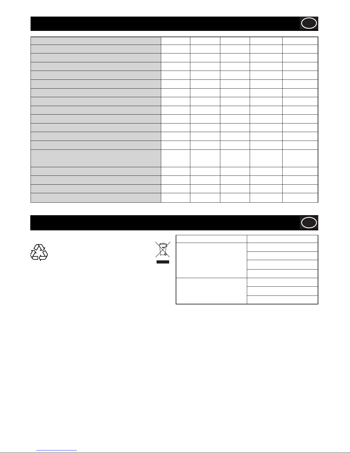
Model Minitile 180 Minitile 200 Minitile 230 Magiktile 180 Maxitile 260
Width (mm) 478 460 585 394 440
Height (mm) 270 260 333 158 1240
Length (mm) 498 330 560 394 1150
Blade Diameter (mm) 180 200 230 180 200
Blade Speed (rpm) 2800 2800 2800 2800 2800
Blade Centre Hole (mm) 25.4 25.4 25.4 25.4 25.4
Max. Cutting Depth (mm) 30 40 70 30 40
Machine Weight (kg) 12 24 30 10 34
Water Tank Capacity (Ltr) 5 2 2 5 25
Motor Power (W) 550 550 1200 550 650
Capacitor (230v 50Hz) (F) 8 8 16 8 10
Capacitor (115v 50Hz) (F) 30 30 70 30 40
Sound Power Level
Lw (Loadless) (dBW(A)) 69.2 71.4 72.4 69.2 69.2
Lw (Underload) (dB(A)) 100 101.5 103.5 100.2 100.2
Lpm (Loadless) (dBW(A)) 62.7 32.7 61.5 32.7 62.7
Lpm (Underload) (dB(A)) 92 92 93.3 92 92
Page 6

6
General Safety
GB
Keep your work area perfectly clean
- Cluttered areas invite injuries.
Consider work area environment
- Don’t expose tools to rain.
- Don’t use tools in damp or wet locations. Keep work area well lit.
- Don’t use tools in presence of fl ammable liquids or gases.
Guard against electric shocks
- Prevent body contact with grounded surfaces.
Keep children away!
- Do not let third parties contact tool or extension cord. All visitors should be kept away from work area.
Store your tools in a safe place
- When not in use, tools should be stored in dry and save places, out of the reach of children.
Don’t force tool
- It will function better and in a safer way at the rate for which it was intended.
Use the right tool
- Don’t use low duty tools or accessories to do the job of a heavy-duty tools. Don’t use tools for purposes not intended.
Dress properly
- Rubber gloves and non-slip footwear are recommended when working outdoors. Wear protective hair covering to contain long hair.
- Use safety glasses.
- Use a mask if working operations are dusty.
Don’t abuse cord
- Never carry tool by cord or yank it to disconnect it from socket.
- Keep cord from heat, oil and sharp edges.
Avoid unsteady positions
- Be sure to work in a safe and balanced position.
Maintain tools with care
- Keep tools sharp and clean for better and safer performance.
- Follow all maintenance advice and instructions to replace accessories subject to wear. Inspect tool cords periodically and, if
damaged, have them repaired by an authorised expert. Check extension cords periodically and replace them if damaged.
- Keep handles dry, clean and free from oil and grease.
Disconnect tools
- When not in use, before servicing, and when changing accessories subject to wear.
Remove service keys from tool
- Form the habit of checking to see that keys and adjusting spanners are removed from tool before turning it on.
Avoid unintentional starting
- Be sure that the switch is off when plugging in the tool.
Extension cords for outdoor works
- When tool is used outdoors, use only extension cords intended for this particular use and so marked.
Stay alert
- Watch what you are doing. Use common sense. Do not operate tool when you are inattentive.
Check tool for damaged parts
- Before further use of the tool, check it and the safety devices for damages and be sure that they operate properly. Check for
functioning and binding of moving parts, breakage of parts, correct mounting, and any other conditions that may affect the
correct operation of the tool.
- Damaged safety devices or other parts should be properly repaired or replaced by an authorised Service Centre unless otherwise
indicated elsewhere in this instruction manual.
- Have defective switches replaced by an authorised Service Centre.
- Do not use tool if its switch cannot be turned on or off.
Warning
- For your personal safety use only accessories recommended in this instruction manual or in the relevant catalogues The use of
any other accessory or attachment other than those recommended in this instruction manual or in the relevant catalogue may
present a risk of personal injury.
Have tools repaired by qualifi ed personnel
- This electric appliance is in accordance with the safety rules in force. Only qualifi ed experts may carry out repairing of electric
appliances otherwise it may cause considerable danger for the user.
When using electric tools, following safety precautions should always be followed to reduce the risk
of fi re, electric shock and personal injuries. Read and follow all these instructions before attempting to
operate this product.
WARNING
Page 7
7
Health and Safety
GB
PPE (Personal Protective Equipment).
Suitable PPE must be worn when using this equipment i.e. Safety Goggles, Gloves, Ear Defenders, Dust Mask and Steel Toe capped
footwear.
Wear clothing suitable for the work you are doing. Tie back long hair and remove any jewellery which may catch in the equipment’s
moving parts.
Dust.
The sawing process will occasionally produce dust, which may be hazardous to your health. Always wear a mask that is suited to the
type of dust being produced.
Pre-Start Checks
GB
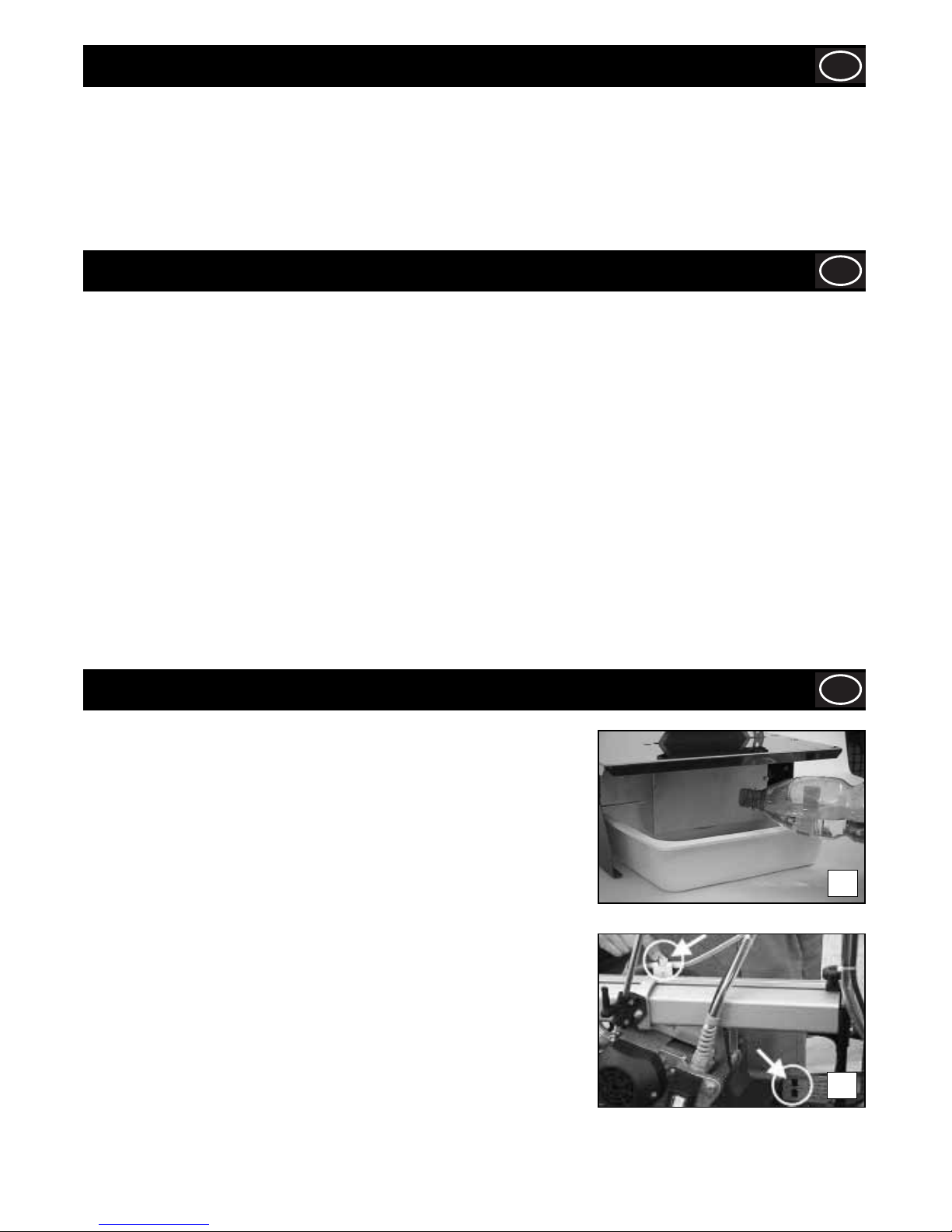
THE MINITILE / MAGIKTILE MACHINE IS DESIGNED FOR WORKING WITH
WATER.
Before and during cutting operations, make sure that the water level is suffi cient to
cover the diamond part of the blade. Fill or top up the basin directly, as shown in the
picture 1a.
In particular cases, it may be necessary to use a tray to recover the cooling water.
If so, use a tray with the following dimensions:
MINITILE 180 = L 50 cm, P 60 cm, H 10 cm
MINITILE 200 = L 50 cm, P 60 cm, H 10 cm
MINITILE 230 = L 60 cm, P 60 cm, H 10 cm
MAGIKTILE 180 = L 50 cm, P 60 cm, H 10 cm
THE MAXITILE MACHINE IS DESIGNED FOR WORKING WITH WATER.
Before any cutting operation, make sure that the water level inside the basin is the
same as the one shown in picture 1b.
Through an on-off valve it is possible to adjust the water fl ow according to the type of
material to be cut. An innovative cooling system makes it possible and allows the disk
to be always wet.
1a
1b
Connecting To The Power Supply
GB
The machine is to be connected to the mains by a residual current circuit breaker (RCCB) or class II isolation transformer with the
following characteristics:
MINITILE 180
RCCB 230V In 3 A Id 20 mA 115V In 6 A Id 20 mA
TRANSFORMER 230V 50 Hz 650 W 115V 50 Hz 650 W
MINITILE 200
RCCB 230V 5 A Id 20 mA 115V 6 A Id 20 mA
TRANSFORMER 230V 50 Hz 650 W 115V 50 Hz 650 W
MINITILE 230
RCCB 230V 10 A Id 20 mA 115V 16 A Id 20 mA
TRANSFORMER 230V 50 Hz 1500 W 115V 50 Hz 1500 W
MAGIKTILE 180
RCCB 230V In 6 A Id 20 mA 115V In 3 A Id 20 mA
TRANSFORMER 230V 50 Hz 650 W 115V 50 Hz 650 W
MAXITILE 260
RCCB 230V In 5 A Id 20 mA 115V In 10 A Id 20 mA
TRANSFORMER 230V 50 Hz 1000 W 115V 50 Hz 1000 W
Page 8
8
Adjusting The Blade Guard
GB
The machine is equipped with a continuous diamond rim blade. Even though this blade has been designed
for operator safety if unintentionally touched, pay particular attention to avoid contact between your fi ngers
and the blade during operation of the machine.
CAUTION
MINITILE & MAGIKTILE ONLY!!
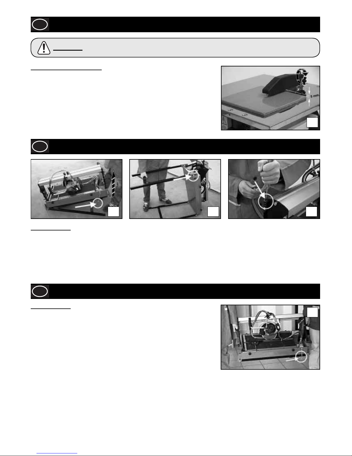
Position the blade guard approximately half a centimetre above the tile surface.
Lock the blade guard in position by fully tightening the screw illustrated in the fi gure.
2
Installation
GB
3a 3b 3c
MAXITILE ONLY!!
Remove the machine from the packaging with the aid of the side carrying handles. To set up the machine for work proceed as follows:
1) Remove the leg lock pin and raise the rear side (pump side) of the machine with the handle until the leg is fully extended
(See picture 3a).
2) Raise the leg by sliding it inside the slot.
3) Repeat the operation for the front side of the machine (See picture 3b).
4) Insert the tube-holder rod in its seat (See picture 3c).
Transportation
GB
MAXITILE ONLY!!
The MAXITILE machine is easy to carry by using the specially provided side handles
(See picture 4).
Before carrying the machine make sure that:
• the motor slide is locked in place with the two cutting adjustment knobs on the slide rail;
• the motor slide is completely lowered and locked with the locking lever;
• the machine is in the 45° (jolly) position and that the inclination adjustment knobs are
properly tightened;
• the tube-holder rod is out of its housing;
• the feet are closed and the leg lock pin inserted.
4
8
Page 9
9
MAXITILE ONLY!!
Cutting at 90°
Thanks to the great versatility of the MAXITILE machine it is possible to carry out different
types of cutting.
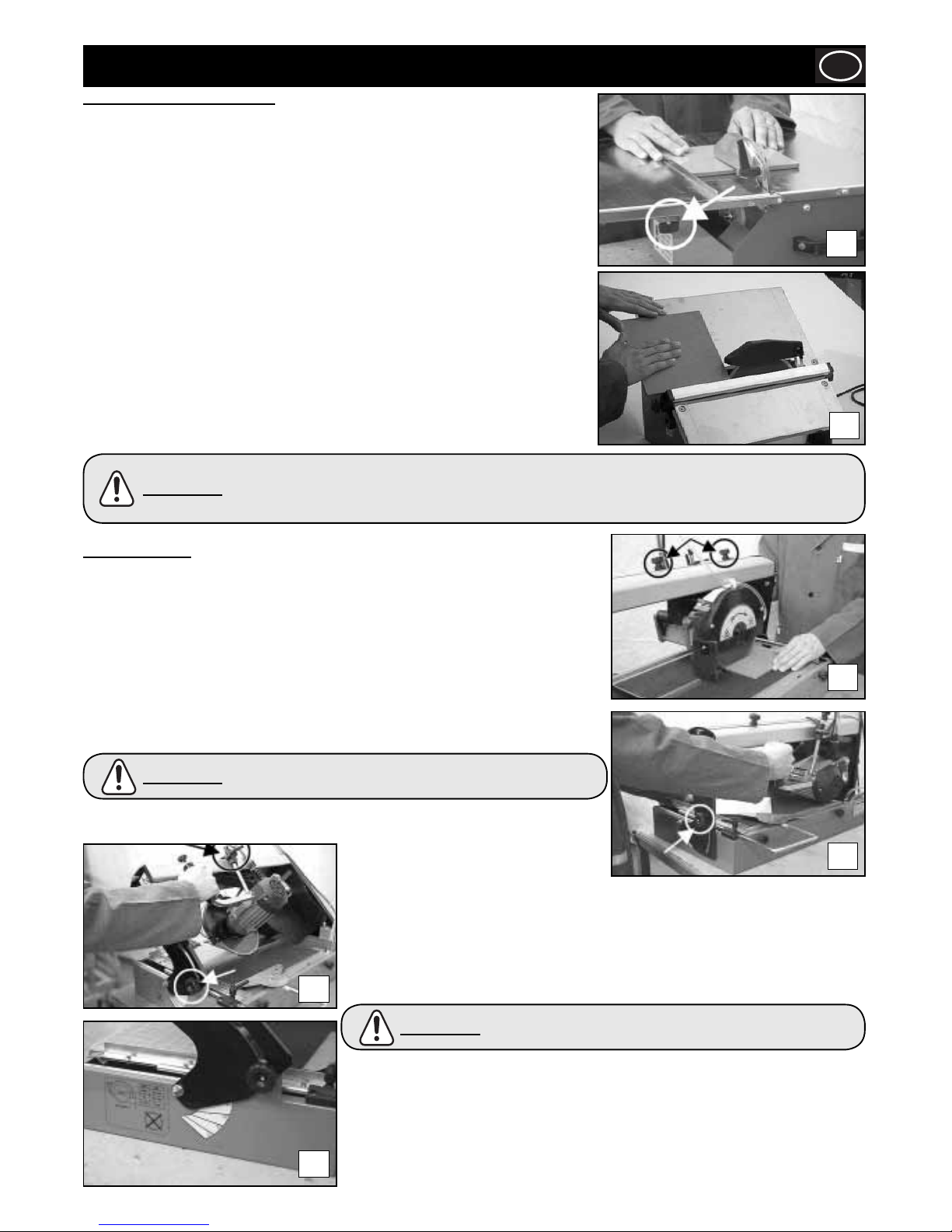
Adjust the blade to the 0° position with the inclination adjustment knobs (See picture 6a).
Position the piece which needs cutting on the working table and make sure that it is
properly up against the tile-stop. If necessary, a square can be of help.
In order to carry out any diagonal cutting lean the tile against the square the way it is
shown in picture 6b and go on with the cutting operation.
Operating Instructions
GB
MINITILE & MAGIKTILE ONLY!!
Cutting at 90°
Position the cutting guide and lock it by tightening the knobs fully. (See Figure 5a)
The picture on the right shows how to position hands correctlyduring cutting at 90°. The
forward movement of the piece must be proportional to the blade cutting capacity, to
prevent hazardous fragments that would involve accidents or injuries from breaking off.
Cutting a surface at 45°
Position the tilting table as shown in fi gure 5b, then lock it in place with the knobs.
Position the cutting guide approx. 2 mm from the diamond blade, then lock it in place by
tightening the knobs fully.
Position the tile with the enamel surface downwards; make sure that the diamond blade
does not come into contact with the tile enamel. Adjust the position of the cutting guide
as necessary.
5a
5b
Figure 5b illustrates the correct position of the hands in the case of 45° angle cuts. Note that the right
hand holds the piece in contact with the diamond blade, while the left hand moves the piece forward.
The forward movement of the piece must be proportional to the blade cutting capacity, to prevent
hazardous fragments which would involve accidentsor injuries from breaking off.
CAUTION
6c
6a
6b
6d
The millimetre ruler placed on the Working table helps only for
linear Cutting.
CAUTION
Cutting at 45°
Adjust the blade to the 45° position with the
inclination adjustment knobs (See picture 6b)
Lock the motor carriage at the max. cutting depth with the locking lever. Picture 6c shows
the proper way the machine should be used.
In order to carry out special working it is possible to set out any cutting inclination ranging
from 0° to 45° as marked on the machine side (See picture 6d).
Before any cutting make sure that the Tile to be cut is properly
up against The tile-stop.
CAUTION
With the MAXITILE machine it is also possible to set out:
a- the cutting length with the cutting adjustment knobs;
b- the cutting depth with the locking lever;
c- the straight cut measurement with the tile bearing square as well as the ruler placed
on the working table;
d- the cutting adjustment with the specially provided indicator and ruler placed on the
slide rail.
Page 10
10
Maintenance
GB
MINITILE & MAGIKTILE ONLY!!
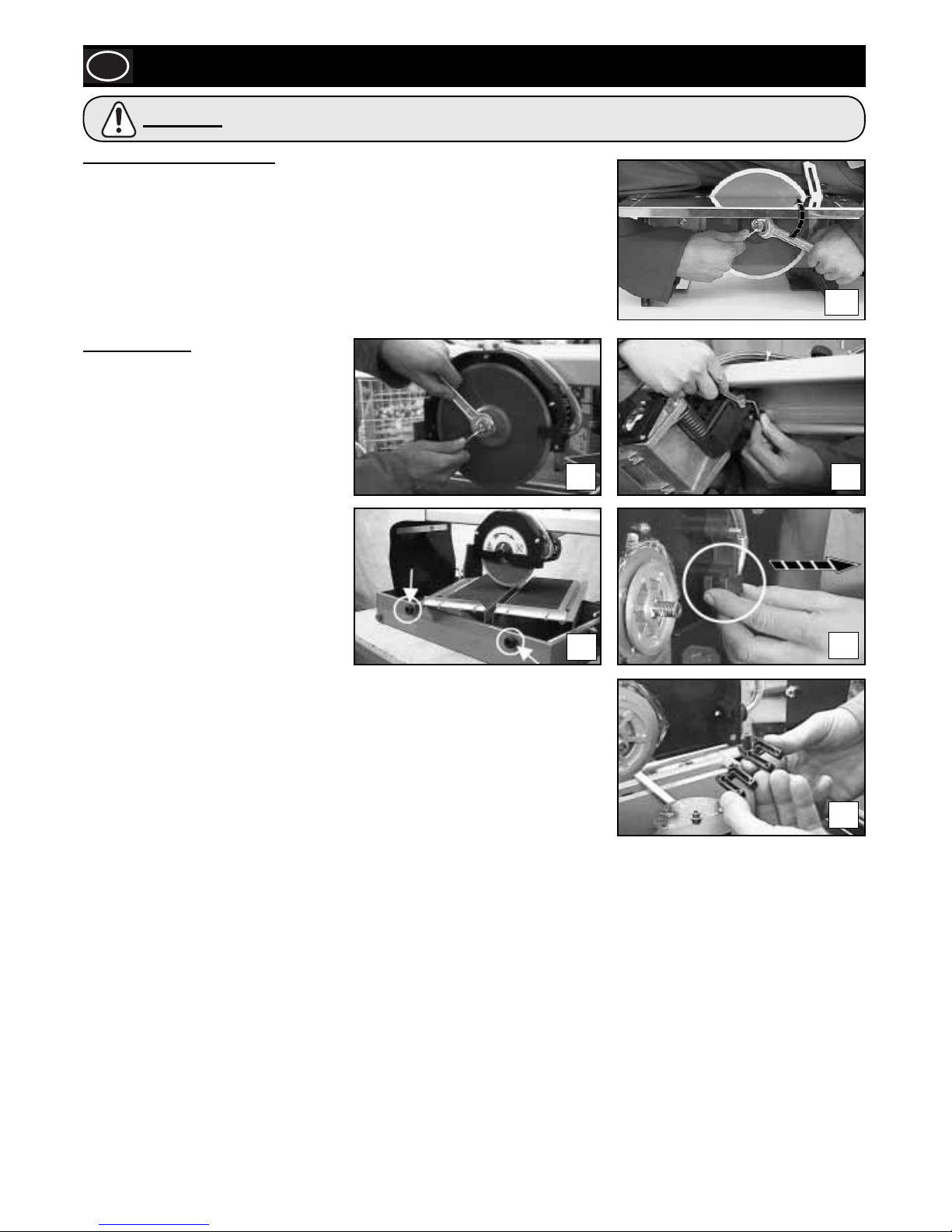
DIAMOND BLADE DISASSEMBLY
Remove the blade guard.
Use the 4mm Allen Key to hold the motor shaft. Unscrew the blade fl ange block nut with
the 19mm spanner.
After removing the blade, clean the blade fl ange thoroughly and check for wear.
Lubricate surfaces with fi ne oil, then fi t new blade.
MAXITILE ONLY!!
After dismantling the blade, clean the blade
fl anges carefully and check them for wear.
Grease any surface with fi ne oil and go on
with the assembly of a new blade.
Check for correct direction of rotation as
clearly indicated on the blade.
MOTOR CARRIAGE ADJUSTMENT
The motor carriage is provided with a register
for the vertical play adjustment. If any
excessive play of the motor carriage should
take place, act as follows:
1) Loosen the register fi xing nut with a
10mm spanner;
2) Screw down the dowel with a 4 mm Allen
Key until the play is eliminated;
3) Lock the register again with the fi xing nut.
CLEANING
It is extremely easy to clean the MAXITILE machine by loosening the side knobs and
dismantling the working table.
Through the side drain remove any residue (See picture 7d).
When necessary clean the sprayer as shown in pictures 7e and 7f
.
7a
Before performing any maintenance operation, ensure the machine is disconnected from the power
supply.
CAUTION
7b
7c
7d
7e
7f
Page 11
11
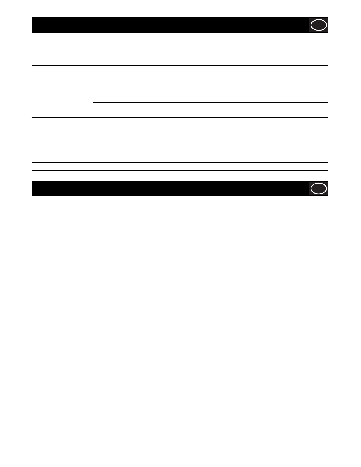
Troubleshooting Guide
GB
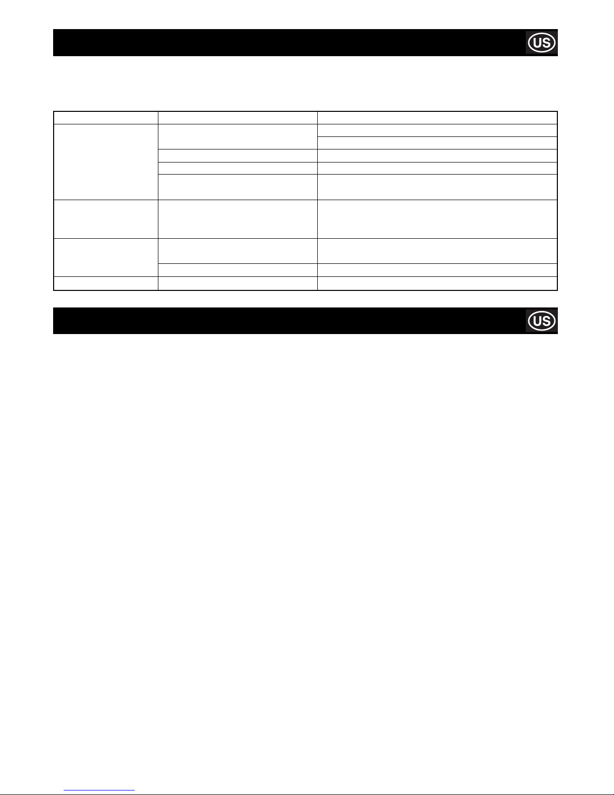
Fault Cause Remedy
The machine does not The power supply cable is damaged or Press the plug fi rmly into the power socket.
function. not properly connected.
No voltage in the socket. Have the socket checked.
Switch is damaged. Consult local dealer.
Diamond blade is bent due to Replace diamond blade.
incorrect use.
If lubrication does not The sprayer unit is clogged. Dismantle the sprayer assembled inside the blade cover
arrive at the blade with the and remove any possible residuals.
pump running.
Motor gives off unpleasant Water may have seeped through inside Unplug the power supply cable and consult local dealer.
odour. the motor.
Capacitor is damaged. Unplug the power supply cable and consult local dealer.
Machine is diffi cult to start. Motor bearings are damaged. Consult local dealer.
Warranty
GB
Your new Belle Group Tile Saw is warranted to the original purchaser for a period of one-year (12 months) from the original date of
purchase. The Belle Group warranty is against defects in design, materials an workmanship.
The following are not covered under the Belle Group warranty:
1. Damage caused by abuse, misuse, dropping or other similar damage caused by or as a result of failure to follow assembly,
operation or user maintenance instructions.
2. Alterations, additions or repairs carried out by persons other than Belle Group or their recognised agents.
3. Transportation or shipment costs to and from Belle Group or their recognised agents, for repair or assessment against a warranty
claim, on any machine.
4. Materials and/or labour costs to renew, repair or replace components due to fair wear and tear.
The following components are not covered by warranty:
• Drive belt(s)
• Engine air fi lter
• Engine spark plug
Belle Group and/or their recognised agents, directors, employees or insurers will not be held liable for consequential or other damages,
losses or expenses in connection with or by reason of or the inability to use the machine for any purpose.
Warranty Claims
All warranty claims should fi rstly be directed to Belle Group, either by telephone, by Fax, by Email, or in writing.
For warranty claims:
Belle Group Warranty Department,
Unit 5, Bode Business Park
Ball Haye Green
Leek
Staffordshire
ST13 6BW.
England.
Tel : +44 (0)1538 380000
Fax : +44 (0)1538 380038
Email : [email protected]
HAVE YOUR MACHINE REPAIRED BY A QUALIFIED PERSON ONLY
This electric machine complies with the relevant safety rules. Repairs should only be carried out by qualifi ed persons using original
spare parts, otherwise this may result in considerable danger to the user.
Page 12
12
How To Use This Manual
This manual has been written to help you operate and service the Tile Saw safely. This manual is intended for dealers and operators of
the Tile Saw.
Foreword
The ‘Environment’ section gives instructions on how to handle the recycling of discarded apparatus in an environmentally friendly way.
The ‘General Safety’ and ‘Health and Safety’ sections explain how to use the machine to ensure your safety and the safety of the
general public.
The ‘Trouble Shooting’ guide helps you if you have a problem with your machine.
The ‘Service & Maintenance’ section is to help you with the general maintenance and servicing of your machine.
The ‘Warranty’ Section details the nature of the warranty cover and the claims procedure.
The ‘Declaration of Conformity’ section shows the standards that the machine has been built to.
Directives with regard to the notations.
Text in this manual to which special attention must be paid are shown in the following way:
The product can be at risk. The machine or yourself can be damaged or injured if procedures are not
carried out in the correct way.
CAUTION
The life of the operator can be at risk.
WARNING
WARNING
Before you operate or carry out any maintenance on this machine YOU MUST READ and STUDY
this manual.
WARNING
Contents
KNOW how to safely use the unit’s controls and what you must do for safe maintenance. (NB Be sure that you know how to switch the
machine off before you switch on, in case you get into diffi culty.)
ALWAYS wear or use the proper safety items required for your personal protection. If you have ANY QUESTIONS about the safe use
or maintenance of this unit, ASK YOUR SUPERVISOR OR CONTACT: BELLE GROUP (UK): +44 (0) 1298 84606
How to use this manual ........................................................................................................................................................................... 12
Warning .................................................................................................................................................................................................... 12
Technical Data .......................................................................................................................................................................................... 13
Environment ............................................................................................................................................................................................. 13
General Safety ......................................................................................................................................................................................... 14
Health & Safety ........................................................................................................................................................................................ 15
Connecting to the Power Supply ............................................................................................................................................................. 15
Pre-Start Checks ...................................................................................................................................................................................... 15
Adjusting the Blade Guard .......................................................................................................................................................................16
Installation ................................................................................................................................................................................................ 16
Transportation .......................................................................................................................................................................................... 16
Operating Instructions ..............................................................................................................................................................................17
Service & Maintenance ............................................................................................................................................................................ 18
Trouble Shooting Guide ........................................................................................................................................................................... 19
Warranty ................................................................................................................................................................................................... 19
Belle Group reserves the right to change machine specifi cation without prior notice or obligation.
Page 13
13
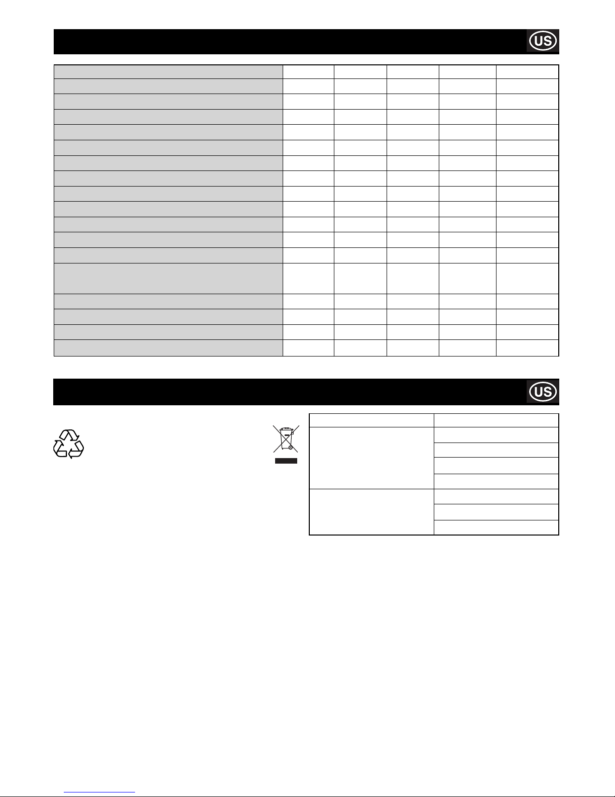
Technical Data
Environment
Safe Disposal.
Instructions for the protection of the
environment. The machine contains valuable
materials. Take the discarded apparatus and
accessories to the relevant recycling facilities.
Component Material
Electric Motor Aluminium
Steel
Copper
Polyamide
Main Body Steel
Polystyrene
Polyamide
Model Minitile 180 Minitile 200 Minitile 230 Magiktile 180 Maxitile 260
Width (in) 18.8 18.1 23.0 15.5 17.3
Height (in) 10.6 10.2 13.1 6.2 48.8
Length (in) 19.6 13.0 22.0 15.5 45.3
Blade Diameter (in) 7.1 7.9 9.1 7.1 7.9
Blade Speed (rpm) 2800 2800 2800 2800 2800
Blade Centre Hole (in) 1 1 1 1 1
Max. Cutting Depth (in) 1.2 1.6 2.8 1.2 1.6
Machine Weight (lbs) 26.5 53.0 66.1 22.0 75.0
Water Tank Capacity (Gals) 1.3 0.5 0.5 1.3 6.6
Motor Power (W) 550 550 1200 550 650
Capacitor (230v 50Hz) (F) 8 8 16 8 10
Capacitor (115v 50Hz) (F) 30 30 70 30 40
Sound Power Level
Lw (Loadless) (dBW(A)) 69.2 71.4 72.4 69.2 69.2
Lw (Underload) (dB(A)) 100 101.5 103.5 100.2 100.2
Lpm (Loadless) (dBW(A)) 62.7 32.7 61.5 32.7 62.7
Lpm (Underload) (dB(A)) 92 92 93.3 92 92
Page 14

14
General Safety
Keep your work area perfectly clean
- Cluttered areas invite injuries.
Consider work area environment
- Don’t expose tools to rain.
- Don’t use tools in damp or wet locations. Keep work area well lit.
- Don’t use tools in presence of fl ammable liquids or gases.
Guard against electric shocks
- Prevent body contact with grounded surfaces.
Keep children away!
- Do not let third parties contact tool or extension cord. All visitors should be kept away from work area.
Store your tools in a safe place
- When not in use, tools should be stored in dry and save places, out of the reach of children.
Don’t force tool
- It will function better and in a safer way at the rate for which it was intended.
Use the right tool
- Don’t use low duty tools or accessories to do the job of a heavy-duty tools. Don’t use tools for purposes not intended.
Dress properly
- Rubber gloves and non-slip footwear are recommended when working outdoors. Wear protective hair covering to contain long hair.
- Use safety glasses.
- Use a mask if working operations are dusty.
Don’t abuse cord
- Never carry tool by cord or yank it to disconnect it from socket.
- Keep cord from heat, oil and sharp edges.
Avoid unsteady positions
- Be sure to work in a safe and balanced position.
Maintain tools with care
- Keep tools sharp and clean for better and safer performance.
- Follow all maintenance advice and instructions to replace accessories subject to wear. Inspect tool cords periodically and, if
damaged, have them repaired by an authorised expert. Check extension cords periodically and replace them if damaged.
- Keep handles dry, clean and free from oil and grease.
Disconnect tools
- When not in use, before servicing, and when changing accessories subject to wear.
Remove service keys from tool
- Form the habit of checking to see that keys and adjusting spanners are removed from tool before turning it on.
Avoid unintentional starting
- Be sure that the switch is off when plugging in the tool.
Extension cords for outdoor works
- When tool is used outdoors, use only extension cords intended for this particular use and so marked.
Stay alert
- Watch what you are doing. Use common sense. Do not operate tool when you are inattentive.
Check tool for damaged parts
- Before further use of the tool, check it and the safety devices for damages and be sure that they operate properly. Check for
functioning and binding of moving parts, breakage of parts, correct mounting, and any other conditions that may affect the
correct operation of the tool.
- Damaged safety devices or other parts should be properly repaired or replaced by an authorised Service Centre unless otherwise
indicated elsewhere in this instruction manual.
- Have defective switches replaced by an authorised Service Centre.
- Do not use tool if its switch cannot be turned on or off.
Warning
- For your personal safety use only accessories recommended in this instruction manual or in the relevant catalogues The use of
any other accessory or attachment other than those recommended in this instruction manual or in the relevant catalogue may
present a risk of personal injury.
Have tools repaired by qualifi ed personnel
- This electric appliance is in accordance with the safety rules in force. Only qualifi ed experts may carry out repairing of electric
appliances otherwise it may cause considerable danger for the user.
When using electric tools, following safety precautions should always be followed to reduce the risk
of fi re, electric shock and personal injuries. Read and follow all these instructions before attempting to
operate this product.
WARNING
Page 15
15
Health and Safety
PPE (Personal Protective Equipment).
Suitable PPE must be worn when using this equipment i.e. Safety Goggles, Gloves, Ear Defenders, Dust Mask and Steel Toe capped
footwear.
Wear clothing suitable for the work you are doing. Tie back long hair and remove any jewellery which may catch in the equipment’s
moving parts.
Dust.
The sawing process will occasionally produce dust, which may be hazardous to your health. Always wear a mask that is suited to the
type of dust being produced.
Pre-Start Checks
THE MINITILE / MAGIKTILE MACHINE IS DESIGNED FOR WORKING WITH
WATER.
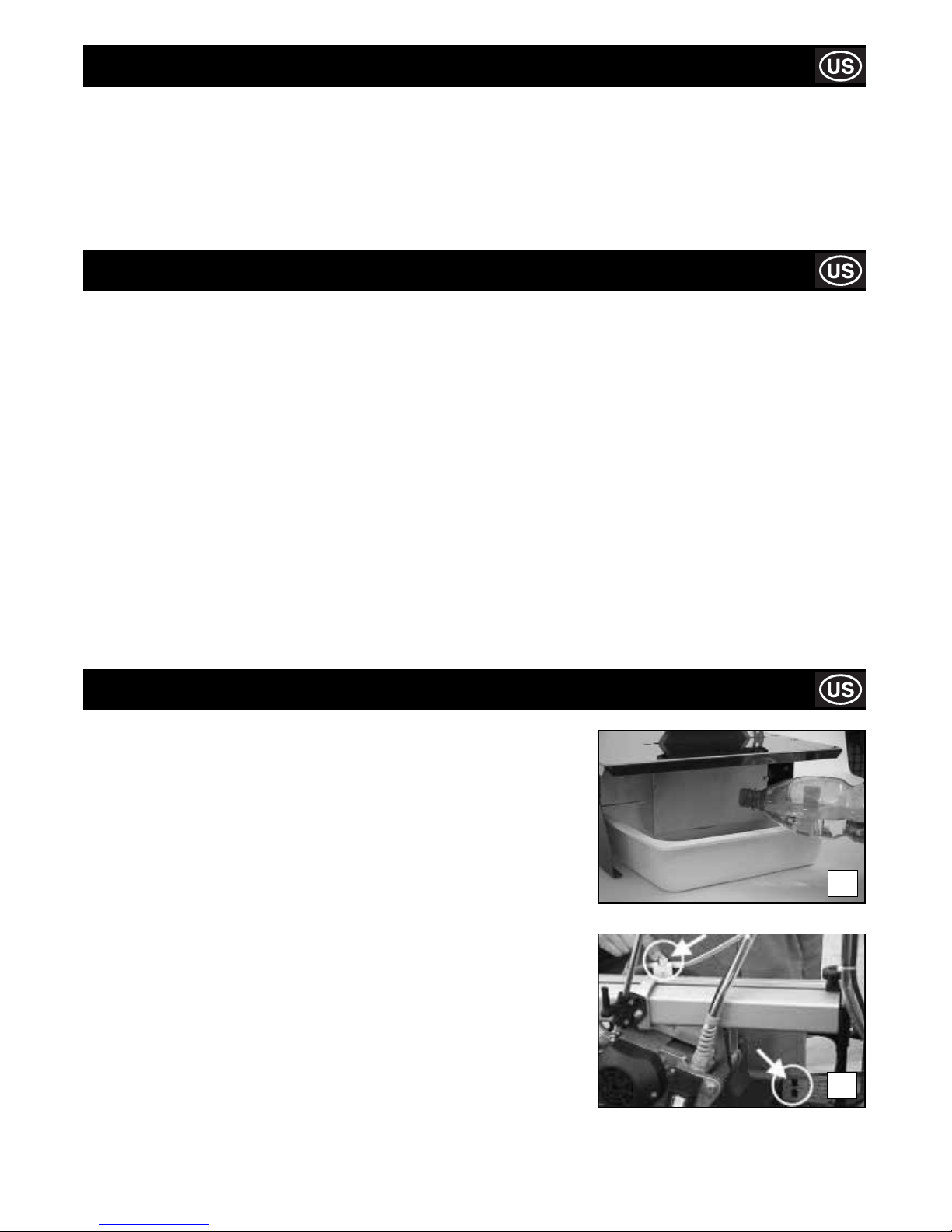
Before and during cutting operations, make sure that the water level is suffi cient to
cover the diamond part of the blade. Fill or top up the basin directly, as shown in the
picture 1a.
In particular cases, it may be necessary to use a tray to recover the cooling water.
If so, use a tray with the following dimensions:
MINITILE 180 = L 19.7 in, P 23.6 in, H 4.0 in
MINITILE 200 = L 19.7 in, P 23.6 in, H 4.0 in
MINITILE 230 = L 23.6 in, P 23.6 in, H 4.0 in
MAGIKTILE 180 = L 19.7 in, P 23.6 in, H 4.0 in
THE MAXITILE MACHINE IS DESIGNED FOR WORKING WITH WATER.
Before any cutting operation, make sure that the water level inside the basin is the
same as the one shown in picture 1b.
Through an on-off valve it is possible to adjust the water fl ow according to the type of
material to be cut. An innovative cooling system makes it possible and allows the disk
to be always wet.
1a
1b
Connecting To The Power Supply
The machine is to be connected to the mains by a residual current circuit breaker (RCCB) or class II isolation transformer with the
following characteristics:
MINITILE 180
RCCB 230V In 3 A Id 20 mA 115V In 6 A Id 20 mA
TRANSFORMER 230V 50 Hz 650 W 115V 50 Hz 650 W
MINITILE 200
RCCB 230V 5 A Id 20 mA 115V 6 A Id 20 mA
TRANSFORMER 230V 50 Hz 650 W 115V 50 Hz 650 W
MINITILE 230
RCCB 230V 10 A Id 20 mA 115V 16 A Id 20 mA
TRANSFORMER 230V 50 Hz 1500 W 115V 50 Hz 1500 W
MAGIKTILE 180
RCCB 230V In 6 A Id 20 mA 115V In 3 A Id 20 mA
TRANSFORMER 230V 50 Hz 650 W 115V 50 Hz 650 W
MAXITILE 260
RCCB 230V In 5 A Id 20 mA 115V In 10 A Id 20 mA
TRANSFORMER 230V 50 Hz 1000 W 115V 50 Hz 1000 W
Page 16
16
Adjusting The Blade Guard
The machine is equipped with a continuous diamond rim blade. Even though this blade has been designed
for operator safety if unintentionally touched, pay particular attention to avoid contact between your fi ngers
and the blade during operation of the machine.
CAUTION
MINITILE & MAGIKTILE ONLY!!
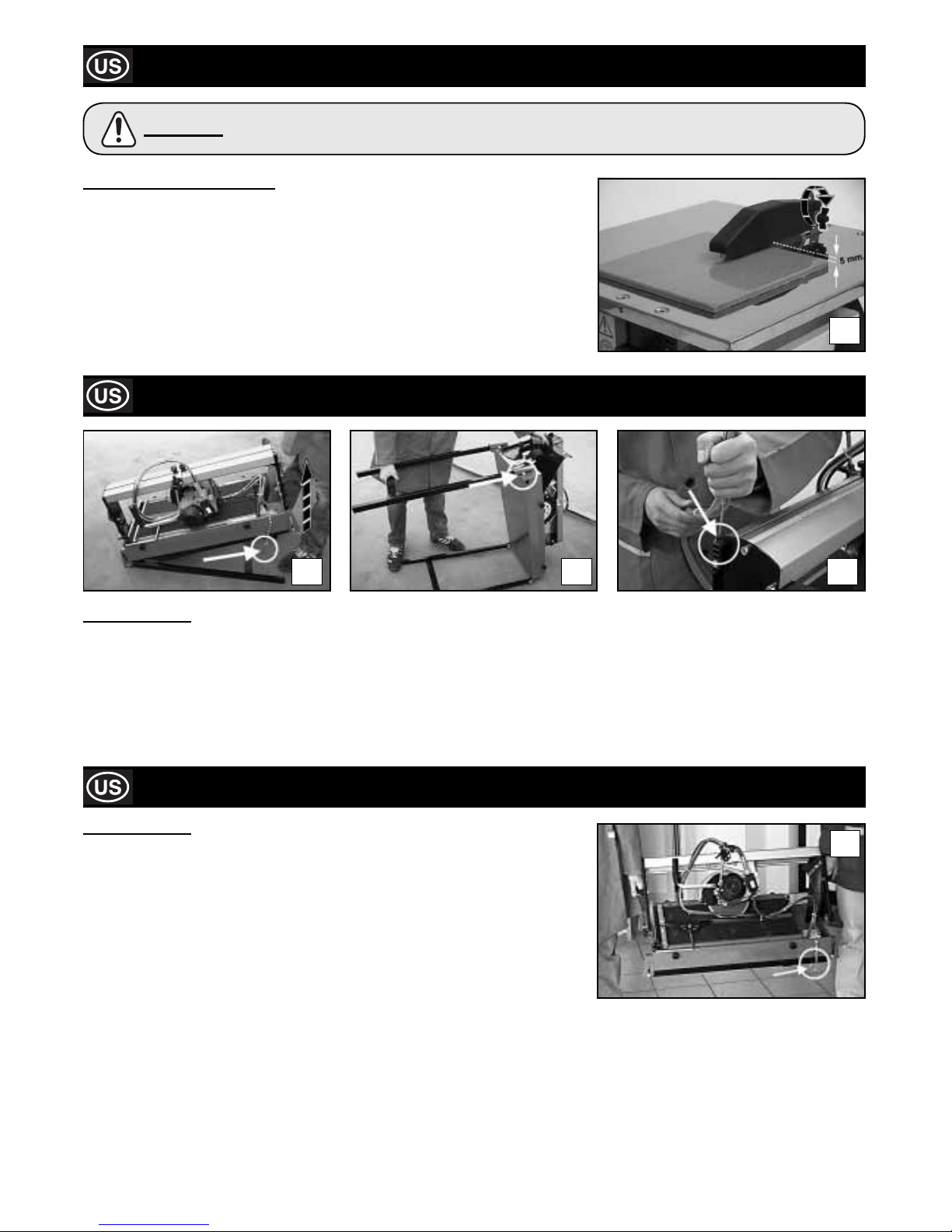
Position the blade guard approximately half a centimetre above the tile surface.
Lock the blade guard in position by fully tightening the screw illustrated in the fi gure.
2
Installation
3a 3b 3c
MAXITILE ONLY!!
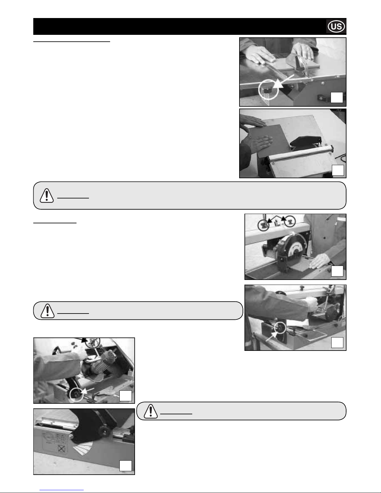
Remove the machine from the packaging with the aid of the side carrying handles. To set up the machine for work proceed as follows:
1) Remove the leg lock pin and raise the rear side (pump side) of the machine with the handle until the leg is fully extended
(See picture 3a).
2) Raise the leg by sliding it inside the slot.
3) Repeat the operation for the front side of the machine (See picture 3b).
4) Insert the tube-holder rod in its seat (See picture 3c).
Transportation
MAXITILE ONLY!!
The MAXITILE machine is easy to carry by using the specially provided side handles
(See picture 4).
Before carrying the machine make sure that:
• the motor slide is locked in place with the two cutting adjustment knobs on the slide rail;
• the motor slide is completely lowered and locked with the locking lever;
• the machine is in the 45° (jolly) position and that the inclination adjustment knobs are
properly tightened;
• the tube-holder rod is out of its housing;
• the feet are closed and the leg lock pin inserted.
4
Page 17
17
MAXITILE ONLY!!
Cutting at 90°
Thanks to the great versatility of the MAXITILE machine it is possible to carry out different
types of cutting.
Adjust the blade to the 0° position with the inclination adjustment knobs (See picture 6a).
Position the piece which needs cutting on the working table and make sure that it is
properly up against the tile-stop. If necessary, a square can be of help.
In order to carry out any diagonal cutting lean the tile against the square the way it is
shown in picture 6b and go on with the cutting operation.
Operating Instructions
MINITILE & MAGIKTILE ONLY!!
Cutting at 90°
Position the cutting guide and lock it by tightening the knobs fully. (See Figure 5a)
The picture on the right shows how to position hands correctlyduring cutting at 90°. The
forward movement of the piece must be proportional to the blade cutting capacity, to
prevent hazardous fragments that would involve accidents or injuries from breaking off.
Cutting a surface at 45°
Position the tilting table as shown in fi gure 5b, then lock it in place with the knobs.
Position the cutting guide approx. 2 mm from the diamond blade, then lock it in place by
tightening the knobs fully.
Position the tile with the enamel surface downwards; make sure that the diamond blade
does not come into contact with the tile enamel. Adjust the position of the cutting guide
as necessary.
5a
5b
Figure 5b illustrates the correct position of the hands in the case of 45° angle cuts. Note that the right
hand holds the piece in contact with the diamond blade, while the left hand moves the piece forward.
The forward movement of the piece must be proportional to the blade cutting capacity, to prevent
hazardous fragments which would involve accidentsor injuries from breaking off.
CAUTION
6c
6a
6b
6d
The millimetre ruler placed on the Working table helps only for
linear Cutting.
CAUTION
Cutting at 45°
Adjust the blade to the 45° position with the
inclination adjustment knobs (See picture 6b)
Lock the motor carriage at the max. cutting depth with the locking lever. Picture 6c shows
the proper way the machine should be used.
In order to carry out special working it is possible to set out any cutting inclination ranging
from 0° to 45° as marked on the machine side (See picture 6d).
Before any cutting make sure that the Tile to be cut is properly
up against The tile-stop.
CAUTION
With the MAXITILE machine it is also possible to set out:
a- the cutting length with the cutting adjustment knobs;
b- the cutting depth with the locking lever;
c- the straight cut measurement with the tile bearing square as well as the ruler placed
on the working table;
d- the cutting adjustment with the specially provided indicator and ruler placed on the
slide rail.
Page 18
18
Maintenance
MINITILE & MAGIKTILE ONLY!!
DIAMOND BLADE DISASSEMBLY
Remove the blade guard.
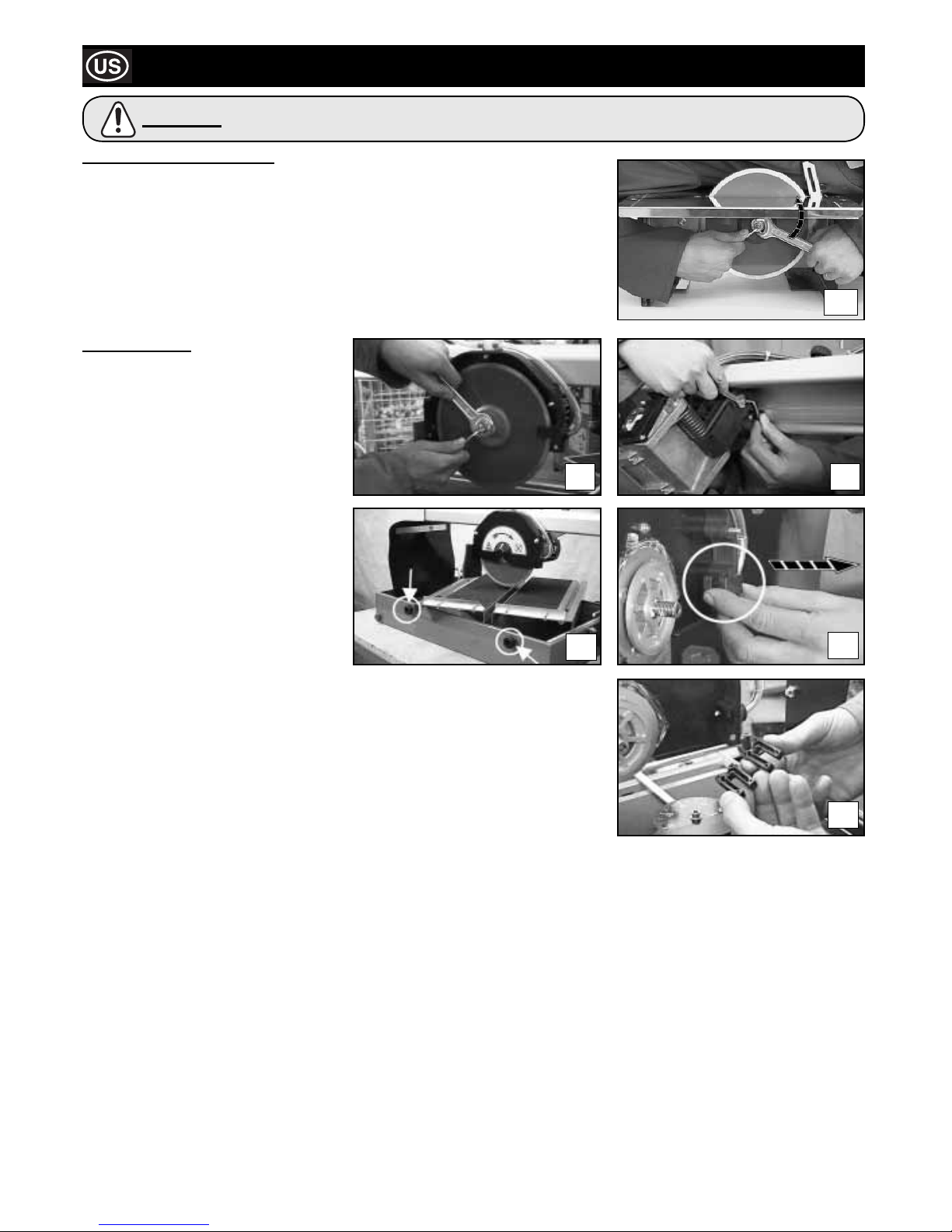
Use the 4mm Allen Key to hold the motor shaft. Unscrew the blade fl ange block nut with
the 19mm spanner.
After removing the blade, clean the blade fl ange thoroughly and check for wear.
Lubricate surfaces with fi ne oil, then fi t new blade.
MAXITILE ONLY!!
After dismantling the blade, clean the blade
fl anges carefully and check them for wear.
Grease any surface with fi ne oil and go on
with the assembly of a new blade.
Check for correct direction of rotation as
clearly indicated on the blade.
MOTOR CARRIAGE ADJUSTMENT
The motor carriage is provided with a register
for the vertical play adjustment. If any
excessive play of the motor carriage should
take place, act as follows:
1) Loosen the register fi xing nut with a
10mm spanner;
2) Screw down the dowel with a 4 mm Allen
Key until the play is eliminated;
3) Lock the register again with the fi xing nut.
CLEANING
It is extremely easy to clean the MAXITILE machine by loosening the side knobs and
dismantling the working table.
Through the side drain remove any residue (See picture 7d).
When necessary clean the sprayer as shown in pictures 7e and 7f
.
7a
Before performing any maintenance operation, ensure the machine is disconnected from the power
supply.
CAUTION
7b
7c
7d
7e
7f
Page 19
19
Troubleshooting Guide
Fault Cause Remedy
The machine does not The power supply cable is damaged or Press the plug fi rmly into the power socket.
function. not properly connected.
No voltage in the socket. Have the socket checked.
Switch is damaged. Consult local dealer.
Diamond blade is bent due to Replace diamond blade.
incorrect use.
If lubrication does not The sprayer unit is clogged. Dismantle the sprayer assembled inside the blade cover
arrive at the blade with the and remove any possible residuals.
pump running.
Motor gives off unpleasant Water may have seeped through inside Unplug the power supply cable and consult local dealer.
odour. the motor.
Capacitor is damaged. Unplug the power supply cable and consult local dealer.
Machine is diffi cult to start. Motor bearings are damaged. Consult local dealer.
Warranty
Your new Belle Group Tile Saw is warranted to the original purchaser for a period of one-year (12 months) from the original date of
purchase. The Belle Group warranty is against defects in design, materials an workmanship.
The following are not covered under the Belle Group warranty:
1. Damage caused by abuse, misuse, dropping or other similar damage caused by or as a result of failure to follow assembly,
operation or user maintenance instructions.
2. Alterations, additions or repairs carried out by persons other than Belle Group or their recognised agents.
3. Transportation or shipment costs to and from Belle Group or their recognised agents, for repair or assessment against a warranty
claim, on any machine.
4. Materials and/or labour costs to renew, repair or replace components due to fair wear and tear.
The following components are not covered by warranty:
• Drive belt(s)
• Engine air fi lter
• Engine spark plug
Belle Group and/or their recognised agents, directors, employees or insurers will not be held liable for consequential or other damages,
losses or expenses in connection with or by reason of or the inability to use the machine for any purpose.
Warranty Claims
All warranty claims should fi rstly be directed to Belle Group, either by telephone, by Fax, by Email, or in writing.
For warranty claims:
Belle Group Warranty Department,
Unit 5, Bode Business Park
Ball Haye Green
Leek
Staffordshire
ST13 6BW.
England.
Tel : +44 (0)1538 380000
Fax : +44 (0)1538 380038
Email : [email protected]
HAVE YOUR MACHINE REPAIRED BY A QUALIFIED PERSON ONLY
This electric machine complies with the relevant safety rules. Repairs should only be carried out by qualifi ed persons using original
spare parts, otherwise this may result in considerable danger to the user.
Page 20
20
Comment Utiliser Ce Manuel
Ce manuel est rédigé pour vous aider à vous servir et à entretenir la ‘Tile Saw’ en toute sécurité. Il est destiné aux concessionnaires et
aux opérateurs de la ‘Tile Saw’.
Avant-propos
La section ‘Respect de l’environnement’ contient des instructions sur les méthodes de recyclage et d’élimination des appareils dans
le respect de l’environnement.
Les sections ‘Consignes de Sécurité Générales’ et ‘Santé et Sécurité’ expliquent la manière dont il faut utiliser l’appareil pour
assurer votre sécurité et celle des membres du public, en général.
La section ‘Dépistage des Anomalies’ vous donne des conseils en cas de problèmes concernant votre appareil.
La section ‘Entretien et Révision’ vous donne des conseils sur l’entretien général et les révisions de votre appareil.
La section ‘Garantie’ donne des renseignements sur la couverture sous garantie et la méthode à suivre pour les réclamations sous
garantie.
La section ‘Déclaration de Conformité’ donne la liste des normes auxquelles l’appareil est conforme.
Renseignements concernant les notations utilisées dans ce manuel.
Dans ce manuel, il faut prêter une attention toute particulière au texte signalé comme suit:
Il peut y avoir un danger mortel pour l’opérateur.
AVERTISSEMENT
Ce produit peut présenter des risques. Si les méthodes indiquées ne sont pas rigoureusement
respectées, l’appareil ou l’opérateur risque de subir des dommages / blessures.
ATTENTION
Avertissment
Sommaire
Il faut SAVOIR comment utiliser les commandes en toute sécurité, et avoir assimilé les mesures à prendre pour effectuer un entretien
en toute sécurité. (NB : Avant de le mettre en route, il faut savoir comment arrêter l’appareil, en cas de diffi cultés éventuelles).
Il faut TOUJOURS porter ou utiliser les articles de protection appropriés pour assurer votre protection personnelle.
Pour TOUTES QUESTIONS EVENTUELLES sur l’utilisation ou l’entretien en toute sécurité de cet appareil, CONSULTEZ VOTRE
RESPONSABLE OU CONTACTEZ BELLE GROUP: +44 (0)1298 84606
Comment Utiliser Ce Manuel ................................................................................................................................................................... 20
Avertissement ........................................................................................................................................................................................... 20
Caractéristiques Techniques ....................................................................................................................................................................21
Respect de l’environnement ..................................................................................................................................................................... 21
Consignes de Sécurité ............................................................................................................................................................................. 22
Santé et Sécurité ...................................................................................................................................................................................... 23
Branchement ............................................................................................................................................................................................ 23
Contrôles Préalables au Démarragee ...................................................................................................................................................... 23
Réglage de la Protection du Disque ........................................................................................................................................................24
Installation ................................................................................................................................................................................................ 24
Transport .................................................................................................................................................................................................. 24
Fonctionnement de la Scie a Sol ............................................................................................................................................................. 25
Entretien ................................................................................................................................................................................................... 26
Recherches des Pannes .......................................................................................................................................................................... 27
Garantie .................................................................................................................................................................................................... 27
Déclaration de Conformité.......................................................................................................................................................................... 2
Belle Group reserves the right to change machine specifi cation without prior notice or obligation.
Avant d’utiliser ou d’effectuer toute intervention d’entretien dans cette machine, il est
IMPERATIF de LIRE et d’ASSIMILER le contenu de ce manuel.
AVERTISSEMENT
Page 21
21
Caractéristiques Techniques
Respect de l’Environnement
Elimination en toute sécurité.
Instructions pour le respect de l’environnement.
Cet appareil contient des matériaux recyclables.
Pour vous débarrasser de l’appareil, prière
d’emmener l’appareil et les accessoires dans
une décharge de recyclage agréé.
Composant Matériau.
Moteur électrique Aluminium
Acier
Cuivre
Polyamide
Corps Principal Acier
Polystyrène
Polyamide
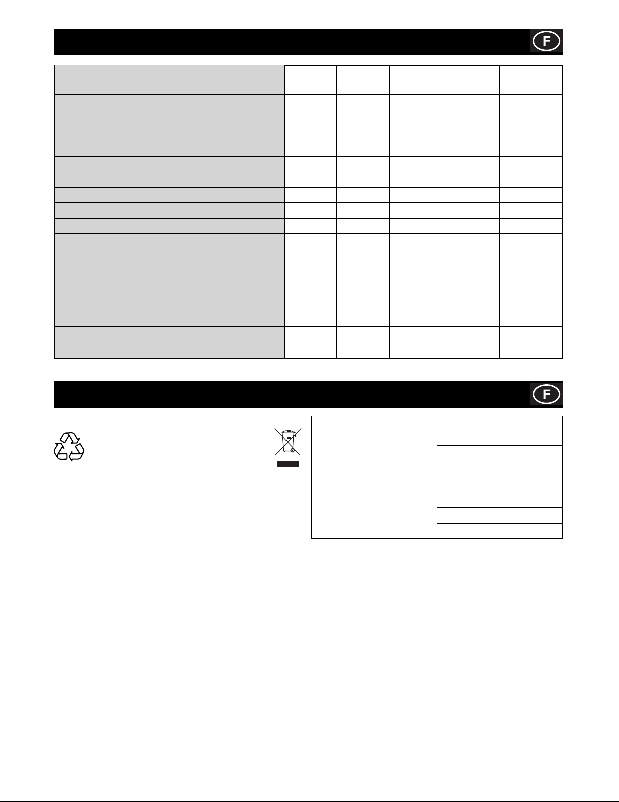
Modèle Minitile 180 Minitile 200 Minitile 230 Magiktile 180 Maxitile 260
Largeur (mm) 478 460 585 394 440
Hauteur (mm) 270 260 333 158 1240
Longeur (mm) 498 330 560 394 1150
Diamètre outil (mm) 180 200 230 180 200
Vitesse de rotation (rpm) 2800 2800 2800 2800 2800
Alésage outil (mm) 25.4 25.4 25.4 25.4 25.4
Profondeur max. de la coupe (mm) 30 40 70 30 40
Masse en service (kg) 12 24 30 10 34
Capacité du réservoir (Ltr) 5 2 2 5 25
Puissance de Moteur (W) 550 550 1200 550 650
Condensateur (230v 50Hz) (F) 8 8 16 8 10
Condensateur (115v 50Hz) (F) 30 30 70 30 40
Niveau de Bruit
Lw (Valeur a vide) (dBW(A)) 69.2 71.4 72.4 69.2 69.2
Lw (Valeurs en charge) (dB(A)) 100 101.5 103.5 100.2 100.2
Lpm (Valeur a vide) (dBW(A)) 62.7 32.7 61.5 32.7 62.7
Lpm (Valeurs en charge) (dB(A)) 92 92 93.3 92 92
Page 22

22
Consignes De Sécurité
Maintenez de l’ordre sur votre lieu de travail
- Le désordre dans le lieu de travail augmente le risque d’accident.
Tenez compte de l’environnement du lieu de travail
- N’exposez pas l’outil à la pluie.
- N’utilisez pas l’outil dans un environnement humide ou mouillé. Maintenez le lieu de travail éclairé.
- N’utilisez pas d’outil en présence de liquides infl ammables ou de gaz.
Protégez-vous contre l’électrocution
- Evitez tout contact avec les surfaces reliées à terre.
Tenez les enfants éloignés!
- Ne permettez pas que d’autres personnes touchent à l’outil ou au cordon. tenez-les éloignées de votre lieu de travail.
Rangez votre outil dans un endroit sûr
- Les outils, quand ils ne sont pas utilisés, doivent être rangés dans un endroit sec, sûr et hors de la portée des enfants.
Ne surchargez pas votre outil
- Il travaillera mieux et plus sûrement dans la plage de puissance indiquée.
Utilisez l’outil adéquat
- N’utilisez pas d’outils ou de dispositifs de trop faible puissance pour exécuter des travaux lourds. N’utilisez pas l’outil à des fi ns et
pour des travaux pour lesquels il n’a pas été conçu.
Portez de vêtements de travail appropriés
- Lors de travaux à l’air libre il est recommandé de porter des gants en caoutchouc et des chaussures à semelle antidérapante.
Coiffez-vous d’un fi let a cheveux s’ils sont longs. Portez des lunettes de protection.
- Utilisez aussi un masque si le travail exécuté dégage de la poussière.
Evitez tout mauvais usage du cordon
- Ne portez pas l’outil par le cordon et ne tirez pas sur celui-ci pour débrancher la fi che de la prise.
- Tenir le cordon à distance des sources de chaleur, de l’huile et des arêtes vives.
Evitez toutes positions instables
- Veillez à ce que votre appui au sol soit ferme et conservez l’équilibre à tout moment.
Entretenez vos outils soigneusement
- Maintenez vos outils affûtes et propres afi n de travailler mieux et plus sûrement.
- Observez les prescriptions d’entretien et les indications de changement de l’outillage. Vérifi ez régulièrement l’état du
cordon d’alimentation et, en cas de détérioration, faites-le changer par un spécialiste reconnu. Vérifi ez le cordon de rallonge
périodiquement et remplacez-le s’il est endommagé. Maintenez les poignées sèches et exemptes d’huile et de graisse.
Débranchez la fi che de la prise
- En cas de non utilisation, avant de procéder à l’entretien et lors du changement d’outil.
Enlevez les clés à outils
- Avant de mettre l’outil en marche, assurez-vous que les clés et outils de réglage ont été retirés.
Evitez tout démarrage involontaire
- Assurez-vous que l’interrupteur est en position d’arrêt quand vous branchez la prise.
Câbles de rallonge pour l’extérieur
- A l’extérieur, n’utilisez que des rallonges homologuées et marquées de cette façon.
Soyez toujours attentif
- Observez votre travail, agissez en faisant preuve de bon sens. N’employez pas l’outil lorsque vous êtes fatigué.
Contrôlez si votre appareil est endommagé
- Avant d’utiliser de nouveau l’outil, vérifi ez soigneusement le parfait fonctionnement des dispositifs de sécurité ou l’éventuelle
présence de pièces endommagées. Vérifi ez si le fonctionnement des pièces mobiles est correct, si elles ne se grippent pas
ou si d’autres pièces sont endommagées. Tous les composants doivent être montés correctement et remplir les conditions pour
garantir le fonctionnement impeccable de l’appareil.
- Tout dispositif de sécurité et toute pièce endommagés, doivent être réparés ou remplacés de manière appropriée par un atelier du
Service Assistance, sauf indication contraire du manuel d’utilisation.
- Les interrupteurs de commande défectueux doivent être remplacés par un réparateur spécialisé.
- N’utilisez aucun outil sur lequel l’interrupteur ne puisse ni ouvrir ni fermer le circuit correctement.
Attention!
- Pour votre sécurité, n’utilisez que les accessoires mentionnés dans le manuel d’utilisation ou les catalogues prévus.
- L’utilisation d’accessoires ou d’outils autres que ceux recommandés dans le manuel d’utilisation ou dans le catalogue, peut signifi er
pour vous un danger personnel de blessure.
Faites réparer votre outil par du personnel qualifi é
- Cet outil est conforme aux normes de sécurité en vigueur. Toute réparation doit être effectuée uniquement par du personnel qualifi é
utilisant des pièces de rechange originales sinon cela peut provoquer des dangers considérables pour l’utilisateur.
Afi n de réduire le risque d’électrocution, de blessure ou d’incendie lors de l’utilisation d’outils
électriques, observez toujours les mesures de sécurité suivantes. Lisez et observez ces
instructions avant d’utiliser l’outil et conservez ces indications.
AVERTISSEMENT
Page 23
23
Santé et sécurité
EPI (Equipement de protection individuelle).
Lors de l’utilisation de cet appareil, il est impératif de porter un EPI approprié (ex. lunettes de protection, gants de
protection, casque antibruit et chaussures à embout d’acier).
Il faut porter des vêtements adaptés au travail. Attachez les cheveux longs pour les dégager et ne portez pas de bijoux
susceptibles de s’accrocher aux pièces mobiles de l’appareil.
Poussière.
Le procédé de compactage produit éventuellement de la poussière qui risque d’être nocive pour la santé. Il faut toujours
porter un masque approprié au type de poussière produite.
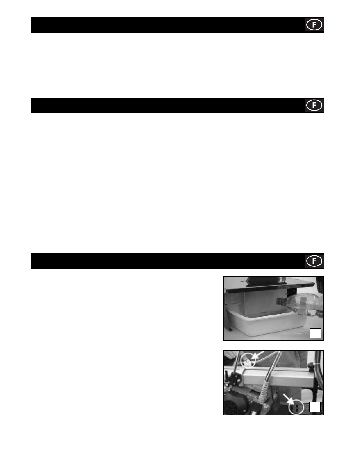
Contrôles Préalables Au Démarrage
LA MAQUINA MINITILE / MAGIKTILE HA SIDO PROYECTADA PARA TRABAJAR
CON AGUA.
Antes de iniciar cualquier operación de corte, y durante la ejecución de la misma,
asegurarse de que el nivel del agua sea sufi ciente para cubrir la parte diamantada del
disco. El llenado o el rellenado pueden efectuarse directamente en la cubeta 1a.
Dans certains cas, il peut s’avérer nécessaire d’utiliser une cuvette pour récupérer l’eau
de réfrigération. Dans ce cas, il est conseillé d’utiliser une cuvette ayant les dimensions
suivantes:
MINITILE 180 = L 19.7 in, P 23.6 in, H 4.0 in
MINITILE 200 = L 19.7 in, P 23.6 in, H 4.0 in
MINITILE 230 = L 23.6 in, P 23.6 in, H 4.0 in
MAGIKTILE 180 = L 19.7 in, P 23.6 in, H 4.0 in
LA MACHINE MAXITILE EST PREVUE POUR FONCTIONNER AVEC DE L’EAU.
Avant de commencer une opération de coupe quelle qu’elle soit, s’assurer que le
niveau d’eau dans la cuve correspond à celui indiqué (photo 1b).
Au moyen de la soupape d’interception située audessus de la protection du disque,
il est possible de modifi er la quantité d’eau en fonction du type de matériau à
couper. Cela est rendu possible par le système de réfrigération innovant qui assure
l’humidifi cation permanente du disque.
1a
1b
Branchement
La machine doit être branchée sur le secteur au moyen d’un disjoncteur différentiel ou d’un transformateur d’isolation de classe II
présentant Les caractéristiques suivantes:
MINITILE 180
DIFFÉRENTIEL 230V In 3 A Id 20 mA 115V In 6 A Id 20 mA
TRANSFORMATUER 230V 50 Hz 650 W 115V 50 Hz 650 W
MINITILE 200
DIFFÉRENTIEL 230V 5 A Id 20 mA 115V 6 A Id 20 mA
TRANSFORMATUER 230V 50 Hz 650 W 115V 50 Hz 650 W
MINITILE 230
DIFFÉRENTIEL 230V 10 A Id 20 mA 115V 16 A Id 20 mA
TRANSFORMATUER 230V 50 Hz 1500 W 115V 50 Hz 1500 W
MAGIKTILE 180
DIFFÉRENTIEL 230V In 6 A Id 20 mA 115V In 3 A Id 20 mA
TRANSFORMATUER 230V 50 Hz 650 W 115V 50 Hz 650 W
MAXITILE 260
DIFFÉRENTIEL 230V In 5 A Id 20 mA 115V In 10 A Id 20 mA
TRANSFORMATUER 230V 50 Hz 1000 W 115V 50 Hz 1000 W
Page 24
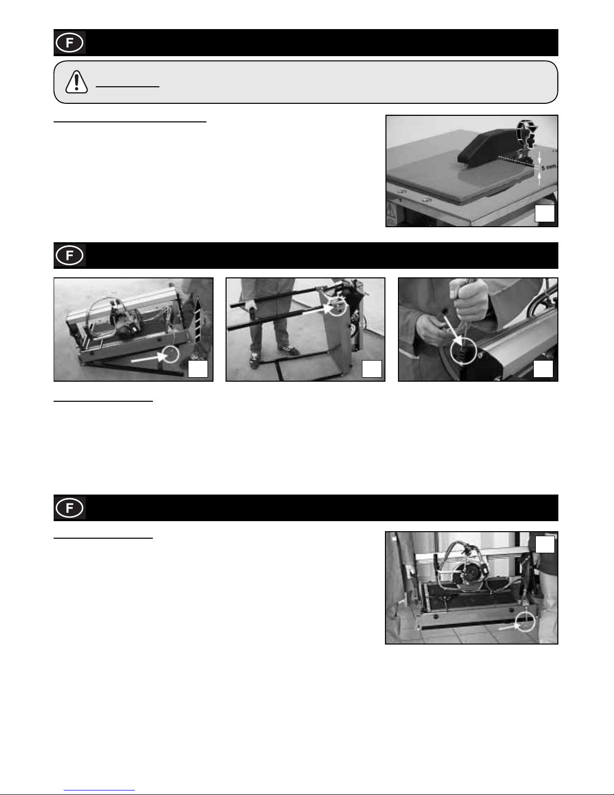
24
Réglage de la Protection du Disque
MINITILE & MAGIKTILE SEULEMENT!!
Posizionare la protezione disco a circa mezzo centimetro al di sopra della superfi cie
della piastrella da tagliare.
Bloccare la protezione disco stringendo a fondo la vite indicata in fi gura.
2
Installation
3a 3b 3c
MAXITILE SEULEMENT!!
Retirez la machine de son emballage au moyen des poignées latérales de manutention.
1) Retirer la sécurité de la tige-épingle, et élever la partie arrière de la machine avec la poignée, jusqu’a ce que le levier soit
complètement tendu (voir image A)
2) Elever le levier en le glissant dans la fente
3) Renouveler l’opération pour la partie avant de la machine (voir l’image B)
4) Insérer la tige de porte tube dans son emplacement (voir image C)
Transport
MAXITILE SEULEMENT!!
La machine MAXITILE est facilement transportable en utilisant les poignées latérales
prévues à cet effet (photo 4). Avant de transporter la machine, il convient de s’assurer
que:
• le chariot moteur est bloqué au moyen des deux boutons de réglage de la coupe
situés sur la poutre de coulissement.
• le chariot moteur est complètement abaissé et bloqué au moyen du levier à reprise.
• la machine est en position 45° (jolly) et les boutons de réglage de l’inclinaison sont
bien serrés.
• la tige porte-tuyau est bien sortie de son logement.
• les pieds sont fermés au moyen du goujon de blocage des béquilles (photo 5).
4
24
La machine est munie d’un disque diamant à couronne continue. Cet outil présente la caractéristique
de ne pas blesser les doigts en cas de choc accidentel. Dans tous les cas, veuillez faire
particulièrement attention lors de l’utilisation de la machine à tout contact entre les doigts et le disque
diamant.
ATTENTION
Page 25
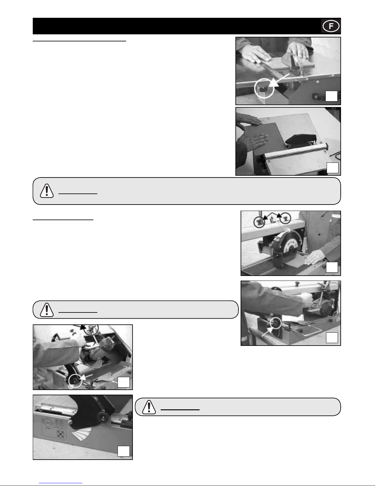
25
MAXITILE SEULEMENT!!
Faire une coupe à plat
La grande souplesse de la machine MAXITILE permet de réaliser différents types de
coupe.
Amener la machine dans la position 0° au moyen des poignées de réglage de l’inclinaison
(photo 6a). Positionner la pièce à couper sur le plan de travail et s’assurer qu’elle est bien
appuyée au dispositif d’arrêt du carreau, en utilisant le cas échéant l’équerre d’appui.
IPour effectuer une coupe diagonale, incliner le carreau contre le carre de la machine,
comme le montre l’image 6b, et poursuivre l’opération de coupe.
Fonctionnement de la Scie a Sol
MINITILE & MAGIKTILE SEULEMENT!!
Faire une coupe à plat
Placez le guide de coupe comme indiqué sur la fi gure et bloquez-le à l’aide des
poignées de blocage. (Fig 5a)
La Fig.5a montre comment placer correctement ses mains lors d’une coupe à plat.
L’avance devra être proportionnelle à la capacité de coupe du disque. De cette
manière, la sécurité sera garantie et les détachements de matériau dangereux
susceptibles de provoquer des accidents seront évités.
Faire une coupe à 45°
Placer le plan mobile comme indiqué sur la fi gure 5b et bloquer les manettes.
Positionner le guide de découpage à environ 2mm du disque diamanté et bloquer en
serrant à fond les manettes.
Positionner le carreau émail orienté vers le plan d’usinage et contrôler que le disque
diamanté n’entre pas en contact avec l’émail. Corriger éventuellement la position de la
butée de découpage.
5a
5b
6c
6a
6b
6d
Faire une coupe à 45°
Amenez le disque de coupe dans la position
45° au moyen des poignées de réglage de
l’inclinaison (photo 6b).
Bloquer le chariot du moteur dans la position de max. profondeur de la coupe en utilisant
le levier de blocage. La façon correcte d’utiliser la machine est indiquée sur la fi gure 6c.
Pour les éventuelles opérations particulières, il est possible de programmer n’importe
quelle inclinaison de coupe comprise entre 0° et 45° (degrés indiqués sur le côté de la
machine (photo 6d).
Avec la machine MAXITILE il est aussi possible de régler:
a- la longueur de la coupe au moyen des poignées de réglage de la coupe.
b- la profondeur de la coupe au moyen du levier de blocage
c- la mesure de coupe droite en utilisant l’équerre d’appui du carreau et la tige graduée
placée sur le plan de travail
d- le centrage de la coupe en utilisant l’indicateur prévu à cet effet et la tige graduée
situés sur la poutre de coulissement.
La position correcte des mains pour les découpages en plan est indiquée sur la fi gure 5b. L’avance
devra être proportionnelle à la capacité de découpage du disque. De cette façon il sera possible de
garantir l’absence de projectionsdangereuses de débris qui pourraient entraîner des blessures ou des
accidents graves.
ATTENTION
La ligne millimetree situee sur le plan de travail sert
uniquement pour l’execution de la coupe lineaire.
ATTENTION
Avant toute operation de coupe, s’assurer que le carreau
est bien appuye contre l’arret d’appui Carreau.
ATTENTION
Page 26
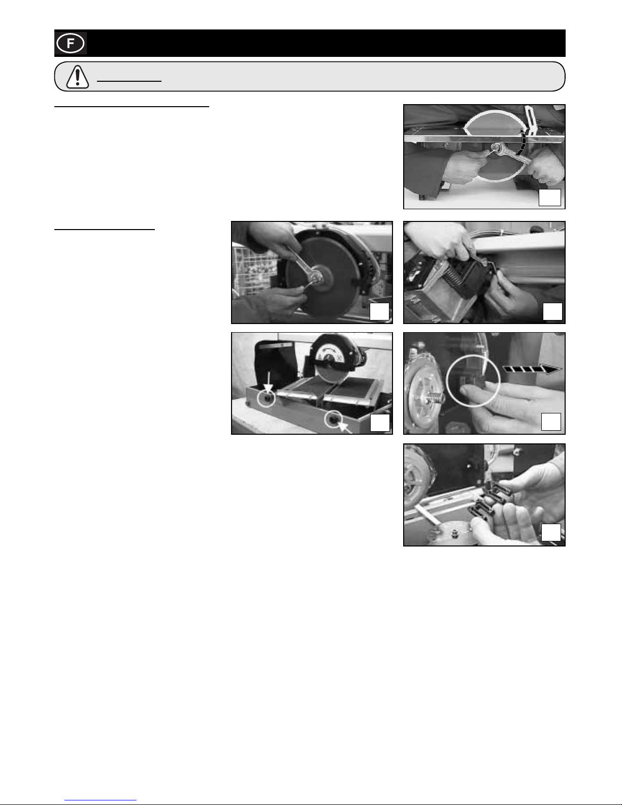
26
Entreten
MINITILE & MAGIKTILE SEULEMENT!!
DEMONTAGE DU DISQUE DIAMANTE
Déposer la protection du disque.
Maintenez bloqué l’arbre du moteur à l’aide de la clef Allen 4 mm. A l’aide de la clé de 19
mm, dévissez l’écrou de blocage de la bride de support du disque.
Une fois le disque démonté, nettoyez soigneusement la bride de support et vérifi ez-en
l’usure. Lubrifi ez les surfaces avec de l’huile fi ne puis procédez au montage du disque
neuf.
MAXITILE SEULEMENT!!
Après avoir démonté le disque, nettoyer
soigneusement les brides porte-disque
et vérifi er l’usure éventuelle. Lubirifi er les
surfaces au moyen d’huile fi n et procéder au
montage du disque neuf, en faisant
attention au sens de rotation imprimé
clairement à l’outil.
REGLAGE DU CHARIOT
Le chariot moteur est doté d’une vis de
réglage du jeu vertical. En cas de jeu
excessif du chariot moteur, procéder comme
suit:
1) Desserrer l’écrou de blocage au moyen
d’une clef métrique 10 mm.
2) Au moyen d’une clef Allen 4 mm, visser la
vis de façon à éliminer le jeu.
3) Bloquer de nouveau la vis au moyen de
l’écrou de blocage.
NETTOYAGE
Il est possible de nettoyer facilement la machine MAXITILE en desserrant les poignées
latérales et en enlevant le plan de travail.
Au moyen du bouchon latéral, éliminer les déchets de production (photo 7d).
Quand cela est nécessaire, procéder au nettoyage du spray de la façon indiquée photos
7e et 7f
.
7a
7b
7c
7d
7e
7f
Avant d’effectuer l’une quelconque des operations decrites dans ce chapitre, assurez-vous que la
machine est bien debranchee.
ATTENTION
Page 27
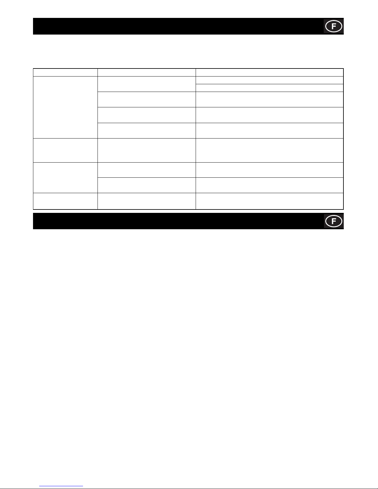
27
Recherche des pannes
Garantie
La ‘Tile Saw’’ de Belle Group est garantie à l’acquéreur d’origine un an (12 mois) à partir de la date originale de l’achat.
La garantie Belle Group s’applique à tous défauts de matériaux ou à un vice de conception ou de fabrication.
La garantie Belle Group ne couvre pas ce qui suit :
1. Dégâts causés par un usage abusif, négligent, une chute ou tous autres dégâts similaires causés par le non-respect des
instructions concernant l’assemblage, l’utilisation ou les opérations d’entretien à effectuer par l’utilisateur, ou résultant de
celle-ci.
2. Toutes modifi cations, additions ou réparations effectuées par des personnes autres que les responsables de Belle Group ou ses
agents agréés.
3. Les frais de transport ou d’expédition pour retourner l’appareil à Belle Group, ou ses agents agréés, et le renvoyer, en vue de le
faire réparer ou évaluer après revendication sous garantie.
4. Les coûts des matériaux et/ou de la main-d’œuvre requis pour remplacer, réparer ou renouveler les composants en raison d’une
usure raisonnable.
Sont exclus de la garantie les composants suivants :
• Courroie(s) d’entraînement
• Filtre à air de moteur
• Bougie de moteur
Belle Group et/ou ses agents agréés, directeurs, employés ou assureurs ne sont pas tenus responsables de tous dégâts
conséquentiels ou autres, pertes ou dépenses encourus en relation avec l’utilisation de l’appareil, ou l’incapacité d’utiliser l’appareil
dans un but quel qu’il soit.
Réclamations sous garantie
Il faut tout d’abord adresser toutes réclamations sous garantie à Belle Group par
téléphone, fax, e-mail ou par courrier.
Pour les revendications sous garantie :
Belle Group Warranty Department,
Unit 5 Bode Business Park,
Ball Haye Green,
Leek,
Staffordshire, ST13 8BW,
Angleterre
Tel : +44 (0)1538 380000
Fax : +44 (0)1538 380038
Email : [email protected]
L’OUTIL DOIT ETRE REPARE PAR DU PERSONNEL QUALIFIE.
Cet outil électrique est conforme aux normes de sécurité en vigueur. Toute réparation doit être effectuée uniquement par du personnel
qualifi é utilisant des pièces de rechange originales sinon cela peut provoquer des dangers considérables pour l’utilisateur.
Problèmes Causes Remèdes
La machine ne fonctionne Le câble d’alimentation est mal Enfoncez à fond la fi che dans la prise, vérifi ez le câble
pas. raccordé ou endommagé. d’alimentation.
Il n’y a pas de tension à la prise de Faites vérifi er la prise de courant.
courant.
L’interrupteur est endommagé. Adressez-vous à votre revendeur habituel pour le
remplacement.
Le disque diamant, à la suite d’une Remplacez le disque diamant.
mauvaise utilisation, s’est plié.
Si le graissage n’arrive pas La conduite de graissage s’est obturée. Démonter le vaporiseur monté à l’intérieur de la protection du
au disque lorsque la disque et nettoyez-le des dépôts éventuels.
pompe est en fonction.
Le moteur dégage de la De l’eau est fi ltrée à l’intérieur du moteur. Débranchez le câble d’alimentation et adressez-vous
mauvaise odeur. à votre revendeur habituel.
Le condensateur est endommagé. Débranchez le câble d’alimentation et adressez-vous
à votre revendeur habituel.
La machine démarre avec Les roulements du moteur sont Débranchez le câble d’alimentation et adressez-vous à
diffi culté. endommagés. votre revendeur habituel.
Page 28
28
Uso De Este Manual
E
Este manual ha sido compilado para ayudarle a operar y mantener con seguridad la sierra para pisos. Este manual está destinado
para el uso de comerciantes y operadores de la sierra para pisos.
Prólogo
La sección dedicada al ‘Medioambiente’ comprende instrucciones sobre el reciclado de aparatos descartados, con el fi n de proteger
el entorno.
Las secciones de ‘Seguridad General’ y de ‘Sanidad y Seguridad’ explican como debe usarse la máquina para asegurar tanto la
seguridad del operador como la del público en general.
La sección de ‘Resolución de Problemas’ le ayudará a resolver los problemas que surjan con la máquina.
La sección de ‘Revisión’ le proporcionará ayuda en el mantenimiento general y en los trabajos de revisión de la máquina.
La sección de ‘Garantía’ da detalles del tipo de garantía y le indica el procedimiento para presentar reclamaciones.
La sección de `Declaración de conformidad´ indica las normas que cumple la máquina.
Directivas relativas a las notas.
El texto de este manual al que se debe prestar atención especial está indicado de la siguiente manera:
Uso De Este Manual ................................................................................................................................................................................28
Aviso ......................................................................................................................................................................................................... 28
Datos Técnicos ........................................................................................................................................................................................ 29
Medioambiente ......................................................................................................................................................................................... 29
Seguridad General ...................................................................................................................................................................................30
Sanidad Y Seguridad ............................................................................................................................................................................... 31
Conexión a la Red Eléctrica .................................................................................................................................................................... 31
Chequeos Antes del Arranque .................................................................................................................................................................... 31
Regulacion de la Proteción del Disco ...................................................................................................................................................... 32
Installation ................................................................................................................................................................................................ 32
Transportation .......................................................................................................................................................................................... 32
Operación ................................................................................................................................................................................................. 33
Mantenimiento .......................................................................................................................................................................................... 34
Localization de Averias ............................................................................................................................................................................ 35
Garantía ................................................................................................................................................................................................... 35
Certifi cado de Conformidad ....................................................................................................................................................................... 2
Belle Group se reserva el derecho de alterar las especifi caciones sin previa notifi cación ni obligación alguna.
La vida del operador corre riesgo.
AVISO
El producto puede representar un riesgo. El incumplimiento de los procedimientos indicados podrá
dañar la máquina o lesionar al operador.
ATENCIÓN
AVISO
E
Indice
APRENDA a emplear con seguridad los comandos de la máquina y lo que se debe hacer para lograr un mantenimiento seguro.
(NOTA: Aprenda bien a desconectar la máquina antes de conectarla, en caso de que se enfrente con difi cultades.)
Lleve o use SIEMPRE los equipos de protección personal necesarios.
En caso de DUDAS sobre el uso o mantenimiento seguros de la máquina, LLAME A SU SUPERVISOR O CONTACTE BELLE
GROUP: +44 (0)1298 84606
E
Antes de operar o realizar ningún trabajo de mantenimiento en esta máquina LEA Y APRENDA BIEN todas
las instrucciones dadas en este manual.
AVISO
Page 29
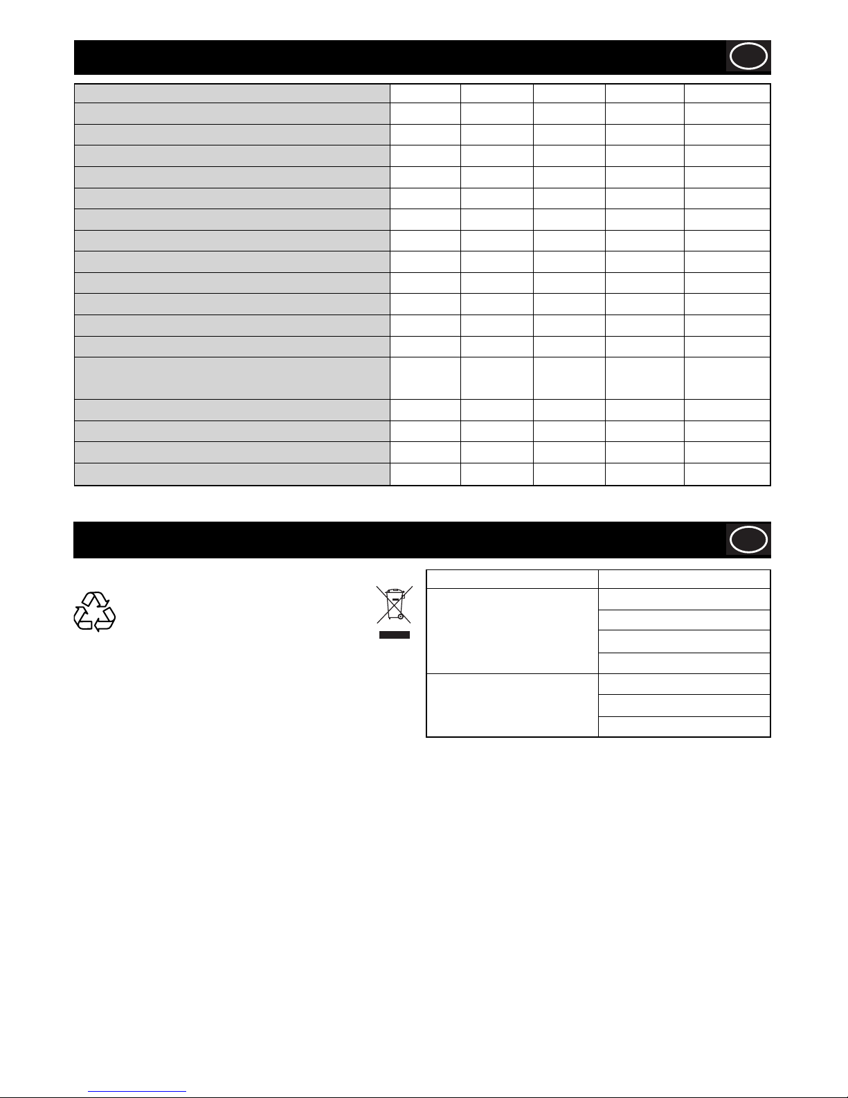
29
Datos Técnicos
E
Medioambiente
E
Eliminación apropiada.
Instrucciones para la protección del
medioambiente. La máquina contiene
materiales valiosos. Lleve la máquina
descartada y sus accesorios a un taller de
reciclado apropiado.
Componente Material
Motor Eléctrico Aluminio
Acero
Cobre
Poliamida
Cuerpo Principal Acero
Poliestireno
Poliamida
Modelo Minitile 180 Minitile 200 Minitile 230 Magiktile 180 Maxitile 260
Anchura (in) 18.8 18.1 23.0 15.5 17.3
Altura (in) 10.6 10.2 13.1 6.2 48.8
Longitud (in) 19.6 13.0 22.0 15.5 45.3
Diámetro herramienta (in) 7.1 7.9 9.1 7.1 7.9
Velocidad de rotación (rpm) 2800 2800 2800 2800 2800
Orifi cio herramienta (in) 1 1 1 1 1
Máxima profundida de cort (in) 1.2 1.6 2.8 1.2 1.6
Massa en servicio (lbs) 26.5 53.0 66.1 22.0 75.0
Capacidad depósito (Gals) 1.3 0.5 0.5 1.3 6.6
Motor Power (W) 550 550 1200 550 650
Condensador (230v 50Hz) (F) 8 8 16 8 10
Condensador (115v 50Hz) (F) 30 30 70 30 40
Intensidad Sonora
Lw (Valores en vacio) (dBW(A)) 69.2 71.4 72.4 69.2 69.2
Lw (Valores bajo carga) (dB(A)) 100 101.5 103.5 100.2 100.2
Lpm (Valores en vacio) (dBW(A)) 62.7 32.7 61.5 32.7 62.7
Lpm (Valores bajo carga) (dB(A)) 92 92 93.3 92 92
Page 30

30
Seguridad General
E
Mantenga ordenado su lugar de trabajo
- El desorden en el área de trabajo aumenta el riesgo de accidentes.
Tenga en cuenta el entorno del área de trabajo
- No exponga el aparato a la lluvia.
- No utilice el aparato en un entorno húmedo o mojado. Procure que el área de trabajo esté bien iluminada.
- No utilice el aparato cerca de líquidos infl amables o gases.
Protéjase contra las descargas eléctricas
- Evite el contacto entre el cuerpo y los objetos conectados a tierra.
Mantenga alejados a los niños
- No permita que otras personas toquen el aparato o el cable. Manténgalas alejadas de su área de trabajo.
Guarde sus herramienta en un lugar seguro.
- Los aparatos que no se utilizan deberían estar guardados en un lugar seco, seguro y fuera del alcance de los niños.
No sobrecargue el aparato
- Trabajará mejor y más seguro si lo hace dentro del margen de potencia indicado.
Utilice el aparato adecuado
- No utilice aparatos de potencia demasiado débil ni accesorios que necesiten una potencia elevada. No utilice el aparato para hacer
trabajos para los que no ha sido concebido.
Vístase con ropa de trabajo apropiada.
- Cuando se hacen trabajos en el exterior, se recomienda llevar guantes de goma y calzado de suela antideslizante. Si su cabello es
largo, téngalo recogido. Lleve gafas de protección
- Utilice también una mascarilla si el trabajo ejecutado produce polvo.
Evite utilizar incorrectamente el cable de alimentación.
- No levante el aparato por el cable ni tire de éste para desconectar la clavija del enchufe.
- Preserve el cable de temperaturas elevadas, del aceite y de las aristas vivas.
- Evite adoptar posiciones inseguras. Mantenga siempre una correcta postura y equilibrio.
Mantenga sus herramientas cuidadosamente.
- Mantenga sus herramientas afi ladas y limpias a fi n de trabajar mejor y más seguro.
- Observe las prescripciones de mantenimiento y las indicaciones de cambio del utillaje. Verifi que con regularidad el estado del cable
de alimentación, y en caso de estar dañado, hágalo cambiar por un técnico cualifi cado autorizado.
Controle con regularidad los cables de extensión y cámbienlos si están dañados. Mantenga las empuñaduras secas y exentas de
aceite y de grasa.
Desenchufe la clavija del enchufe
- En caso de no utilización del aparato, antes de efectuar reparaciones y cuando cambie accesorios .
Retire las llaves de maniobra.
- Antes de poner el aparato en marcha asegúrese de que las llaves y útiles de reglaje hayan sido retirados.
Evite los arranques involuntarios.
- Asegúrese de que el interruptor esté “apagado” cuando se conecta el enchufe del aparato.
Cables de prolongación para el uso en el exterior.
- Cuando la herramienta se utiliza en el exterior, usen solamente alargadoras homologadas e identifi cadas para ello
Esté siempre alerta.
- Observe su trabajo. Use el sentido común y no use el aparato cuando esté distraído
Controle si su aparato esta dañado.
- Antes de usar de nuevo el aparato, verifi que cuidadosamente los dispositivos de seguridad y las piezas posiblemente dañadas.
Verifi que si el funcionamiento de las piezas móviles es correcto, si no se gripan, o si otras piezas están rotas; si todos los otros
componentes están montados correctamente y reúnen las condiciones para garantizar el funcionamiento impecable del aparato.
- Todo dispositivo de seguridad y toda pieza dañada, tienen que ser reparados o sustituidos de forma apropiada en un taller del
servicio posventa, si no se indica otra cosa en el manual de empleo.
- Todo interruptor de mando defectuoso tienen que ser reemplazado por un taller del servicio posventa.
- No utilice ningún aparato cuyo interruptor no pueda abrir y cerrar su circuito correctamente.
Atención
- El uso de accesorios distintos de los mencionados en el manual de instrucciones o recomendados en el catálogo del fabricante de
la máquina, puede signifi car un riesgo de lesiones personales.
Haga reparar su herramienta por personal cualifi cado.
- Este aparato eléctrico cumple las relativas normas de seguridad en vigor. Las reparaciones tienen que ser efectuadas solamente
por personal cualifi cado que utilice piezas de repuesto originales, de no ser así se puede provocar un considerable peligro para el
operador.
Cuando utilice aparatos eléctricos, observe las siguientes medidas de seguridad, a fi n de reducir el riesgo
de descargas eléctricas, de lesiones y de incendio. Lea y observe todas estas instrucciones antes de utilizar
el aparato y conserve bien estas instrucciones.
AVISO
Page 31
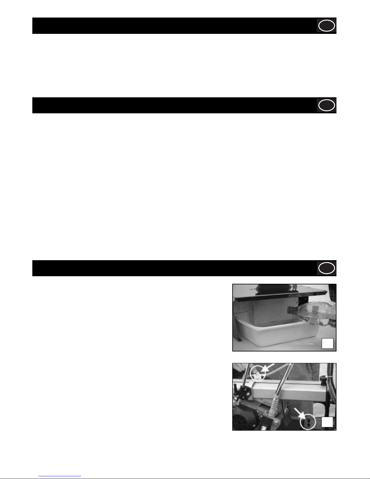
31
Sanidad y Seguridad
E
Equipos de protección personal (EPP)
Se deben llevar equipos adecuados de protección personal, por ejemplo, gafas de seguridad, guantes, protectores del oído, caretas
antipolvo y calzado con punteras de acero.
Lleve ropa adecuada para el trabajo en curso. Sujete debidamente el cabello largo y quítese todo artículo de joyería que pudiera
agarrarse con las partes móviles de la máquina.
Polvo
El proceso de aserrado producirá a veces polvo que puede ser perjudicial para la salud. Lleve siempre una careta apropiada al tipo de
polvo producido.
Chequeos Antes Del Arranque
E
LA MINITILE / MAGIKTILE HA SIDO PROYECTADA PARA TRABAJAR CON AGUA.
Antes de iniciar cualquier operación de corte, y durante la ejecución de la misma,
asegurarse de que el nivel del agua sea sufi ciente para cubrir la parte diamantada del
disco. El llenado o el rellenado pueden efectuarse directamente en la cubeta.
En casos particulares puede ser necesario usar un recipiente para recuperar el agua
de refrigeración. En tal caso, aconsejamos utilizar un recipiente con las siguientes
dimensiones:
MINITILE 180 = L 19.7 in, P 23.6 in, H 4.0 in
MINITILE 200 = L 19.7 in, P 23.6 in, H 4.0 in
MINITILE 230 = L 23.6 in, P 23.6 in, H 4.0 in
MAGIKTILE 180 = L 19.7 in, P 23.6 in, H 4.0 in
LA MAXITILE HA SIDO PROYECTADA PARA TRABAJAR CON AGUA.
Antes de iniciar cualquier operación de corte, verifi car que el nivel del agua de la
cubeta sea el indicado en ella (foto 1b)
Mediante la válvula de corte colocada sobre laprotección del disco es posible variar
la cantidad de agua en base al tipo de material que haya que cortar. Esto es posible
gracias al innovador sistema de refrigeración que permite mantener el disco mojado
continuamente.
1a
1b
Conexiòn a la Red Elèctrica
E
La máquina debe conectarse a la red eléctrica mediante un interruptor diferencial o un transformador de aislamiento en clase II, con
las siguientes características:
MINITILE 180
DIFERENCIAL 230V In 3 A Id 20 mA 115V In 6 A Id 20 mA
TRANSFORMADOR 230V 50 Hz 650 W 115V 50 Hz 650 W
MINITILE 200
DIFERENCIAL 230V 5 A Id 20 mA 115V 6 A Id 20 mA
TRANSFORMADOR 230V 50 Hz 650 W 115V 50 Hz 650 W
MINITILE 230
DIFERENCIAL 230V 10 A Id 20 mA 115V 16 A Id 20 mA
TRANSFORMADOR 230V 50 Hz 1500 W 115V 50 Hz 1500 W
MAGIKTILE 180
DIFERENCIAL 230V In 6 A Id 20 mA 115V In 3 A Id 20 mA
TRANSFORMADOR 230V 50 Hz 650 W 115V 50 Hz 650 W
MAXITILE 260
DIFERENCIAL 230V In 5 A Id 20 mA 115V In 10 A Id 20 mA
TRANSFORMADOR 230V 50 Hz 1000 W 115V 50 Hz 1000 W
Page 32
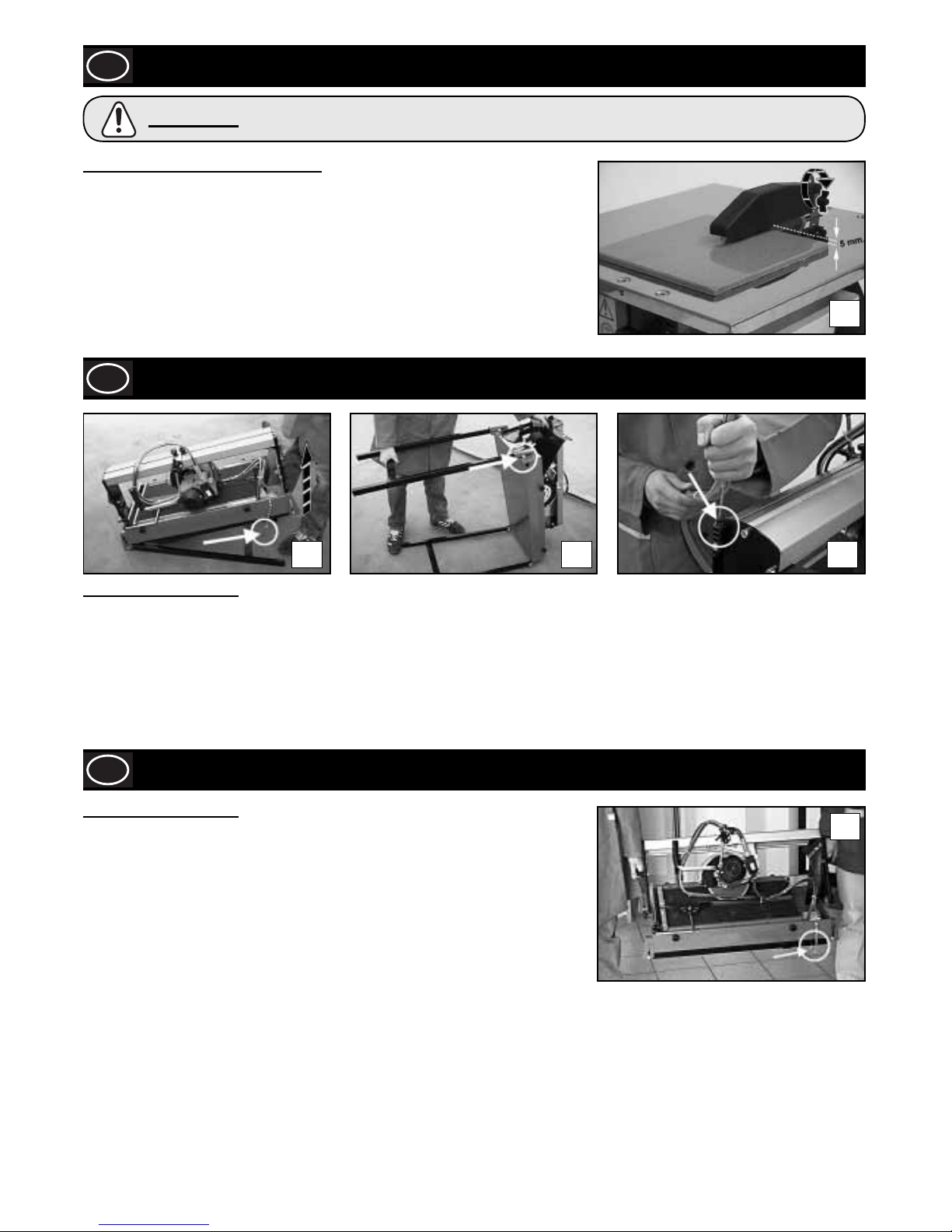
32
Adjusting The Blade Guard
E
MINITILE & MAGIKTILE SOLAMENTE!!
Situar la protección del disco a aproximadamente medio centímetro por encima de la
superfi cie del azulejo a cortar. Bloquear la protección del disco apretando a fondo el
tornillo indicado en la fi gura.
2
Instalaciòn
E
3a 3b 3c
MAXITILE SOLAMENTE!!
Sacar la máquina del embalaje mediante los mangos laterales de transporte. Para poner la máquina en posición de trabajo proceder
de la manera siguiente:
1) Quitar la clavija de bloqueo de las patas y levantar el lado posterior de la máquina (lado bomba) por medio del mango hasta que la
pata salga completamente (foto 3a)
2) Levantar la pata haciéndola deslizar dentro de la ranura.
3) Repetir la operación para la parte delantera (foto 3b)
4) Introducir la varilla que sujeta el tubo en su alojamiento correspondiente (foto 3c)
Transportation
E
MAXITILE SOLAMENTE!!
La MAXITILE es una máquina fácil de transportar gracias a los mangos laterales
(foto 4).
Antes de transportar la máquina, verifi car que:
• El carro motor esté bloqueado por medio de los dos pomos de regulación de corte de la viga de
deslizamiento del carro.
• El carro motor esté completamente bajado y bloqueado por medio de la palanca de bloqueo.
• La máquina esté en posición de 45°(jolly) y los pomos que regulan la inclinación bien
apretados.
• La varilla que sujeta el tubo esté fuera de su alojamiento
• Los soportes estén cerrados con la clavija de bloqueo de patas introducida.
4
32
La máquina está dotada de disco diamantado con corona continua. Este aparato tiene la característica de no herir
los dedos si se la golpea accidentalmente. En todo caso, prestar particular atención, durante el uso de la máquina,
al contacto de los dedos con el disco diamantado.
ATENCIÓN
Page 33
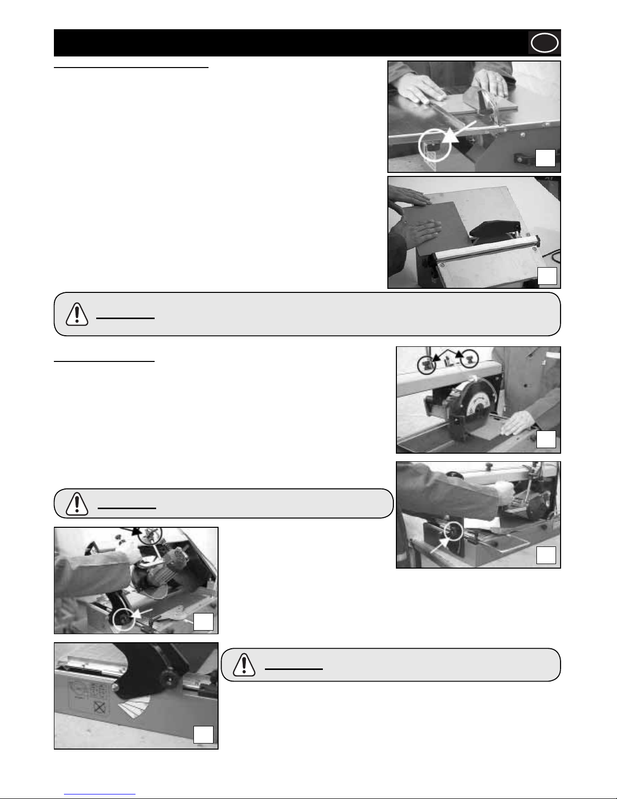
33
MAXITILE SOLAMENTE!!
Ejecuciòn del corte en superfi cie plana
La gran versatilidad de la MAXITILE permite realizar diferentes tipos de corte.
Poner el disco en posición 0° mediante los pomos de regulación de la inclinación
(foto 6a). Colocar la pieza que hay que cortar en el plano de trabajo asegurándose de
que esté bien apoyada en el tope del azulejo, ayudándose con la escuadra de apoyo.
Para efectuar cortes diagonales hay que apoyar el azulejo a la escuadra como indica la
fi gura (foto 6b) y proceder con el corte.
Operación
E
MINITILE & MAGIKTILE SOLAMENTE!!
Ejecuciòn del corte en superfi cie plana
Situar la guía de corte y bloquearla mediante las manillas de fi jación, (Figura 5a)
En la fi gura 4 aparece indicada la posición correcta de las manos durante la ejecución
del corte en superfi cie plana. El avance debe ser proporcional a la capacidad de corte
del disco. De esa forma se tendrá la seguridad de no producir desprendimientos de
materiales que podrían provocar accidentes o heridas.
Ejecuciòn del corte en 45 grados
Ubicar la superfi cie móvil como se indica en la fi gura y bloquearlo mediante las
manillas posicionables.
Colocar la guía de corte a unos 2 mm del disco diamantado y bloquearla apretando a
fondo los pomos.
Situar el azulejo con la superfi cie esmaltada hacia el plano de trabajo y controlar que
el disco diamantado no entre en contacto con el esmalte del azulejo. En caso de ser
necesario corregir la posición de laguía de corte.
5a
5b
6c
6a
6b
6d
Ejecuciòn del corte en 45 grados
Poner el disco de corte en posición 45°
mediante los pomos de regulación de la
inclinación (foto 6a).
Bloquear el carro motor en la posición de máxima profundidad utilizando la palanca de
bloqueo. En la foto 6c está indicado el modo correcto de utilizar la máquina.
Para efectuar eventuales elaboraciones especiales es posible establecer cualquier
inclinación de corte incluida la inclinación entre 0 y 45 grados indicados en el lado de la
máquina (foto 6d).
Con la MAXITILE es posible establecer:
a- La longitud de corte mediante los pomos de regulación.
b- La profundidad de corte utilizando la palanca de bloqueo (foto 6).
c- La medida del corte recto usando la escuadra de apoyo del azulejo y la varilla
graduada colocada en el plano de trabajo (foto 4).
d- El centrado del corte utilizando el indicador a tal efecto y la varilla graduada
colocada sobre la viga de deslizamiento.
En la fi gura 4 aparece indicada la posición correcta de las manos durante la ejecución del corte en
superfi cie plana.El avance debe ser proporcional a la capacidad de corte del disco. De esa forma se
tendrá la seguridad de no producir desprendimientos de materiales que podrían provocar accidentes o
heridas.
ATENCIÓN
La línea milimetrada colocada en el plano de trabajo, sirve
sólo para ejecutar cortes lineales.
ATENCIÓN
Antes efectuar un corte hay que asegurarse de que el
azulejo que hay que cortar esté bien apoyado al tope
De apoyo del azulejo.
ATENCIÓN
Page 34
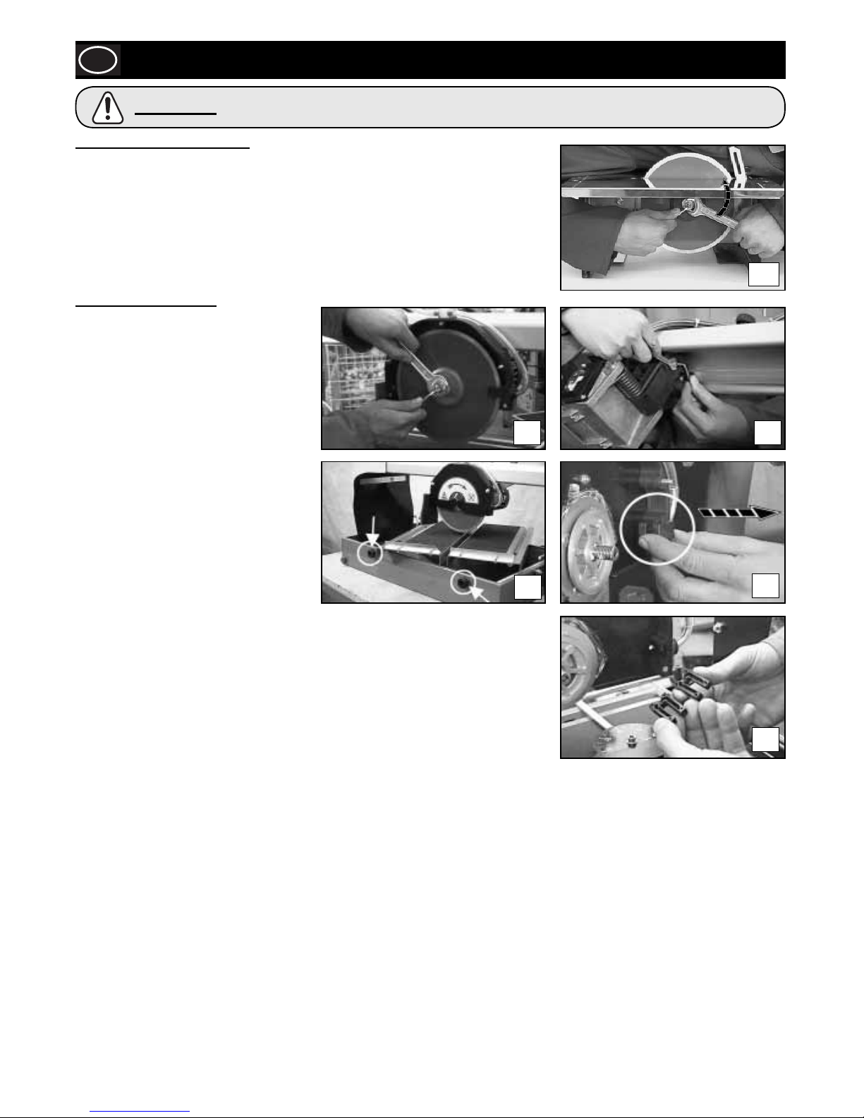
34
Mantenimiento
E
MINITILE & MAGIKTILE ONLY!!
DESMONTAJE DEL DISCO DIAMANTATO
Retirar el cárter de protección del disco.
Mediante la llave Allen de 4mm. mantener bloqueado el eje del motor. Mediante la llave fi ja
de 19mm, desatornillar la tuerca de bloqueo de la brida portadisco.
Luego de haber desmontado el disco, limpiar cuidadosamente las bridas portadisco y
controlar su nivel de desgaste. Lubricar las superfi cies con aceite delgado y proceder al
montaje del nuevo disco.
MAXITILE SOLAMENTE!!
Tras haber desmontado el disco, limpiar con
esmero las bridas de protección del disco y
verifi car el posible desgaste.
Lubricar con aceite fi no las superfi cies y
proceder con el montaje del nuevo disco,
prestando atención al sentido de rotación
indicado claramente sobre la
herramienta.
REGULACIÓN DEL CARRO
El carro motor cuenta con un registro para la
regulación del juego vertical. En caso de que
exista un juego excesivo del carro del motor
hay que proceder de la siguiente manera:
1) Afl ojar la tuerca que bloquea el registro
con una llave métrica de 10mm.
2) Con una llave de cabeza hueca
hexagonal de 4mm enroscar el pasador
hasta que desaparezca el juego
existente.
3) Bloquear otra vez el registro con la tuerca de bloqueo.
LIMPIEZA
Es posible limpiar fácilmente la MAXITILE afl ojand los pomos laterales y quitando el plano
de trabajo.
Por medio del tapón lateral vaciar de la máquina los residuos de la elaboración (foto 7d).
Cuando sea necesario, limpiar el inyector como indica la fi gura (foto 7e y 7f).
7a
7b
7c
7d
7e
7f
Antes de iniciar cualquiera de las operaciones incluidas en el presente capítulo, asegurarse de que la
máquina esté desconectada de la red eléctrica.
ATENCIÓN
Page 35
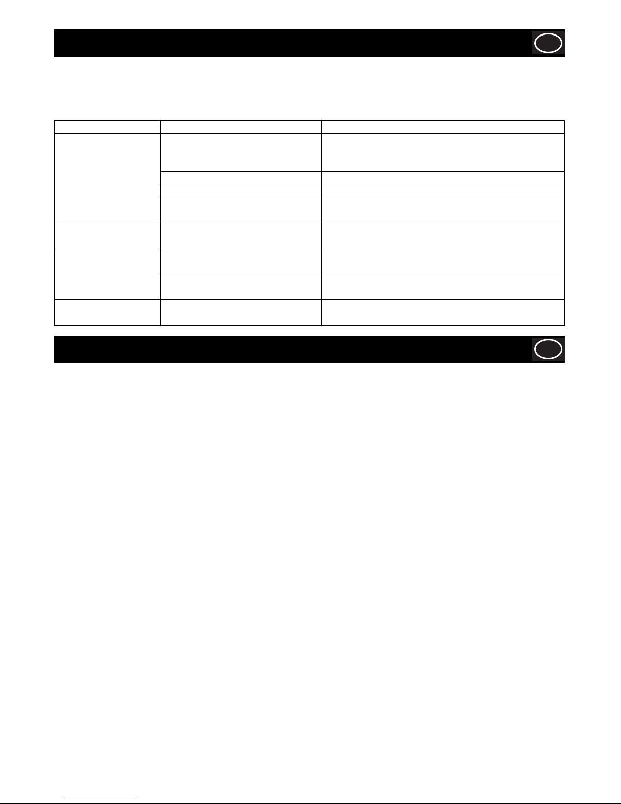
35
Localizaciòn de averias
E
Garantía
E
La ‘TileSaw’ lleva una garantía para el comprador original con una validez de un año (12 meses) a partir de la fecha original de
compra. La garantía de Belle Group le ampara contra defectos de diseño, materiales y mano de obra.
La garantía de Belle Group no cubre lo siguiente:
1. Daños causados por el abuso, mal uso, caída u otros daños similares causados por o como resultado del incumplimiento de las
instrucciones de ensamblaje, operación o mantenimiento por parte del usuario.
2. Las alteraciones, adiciones o reparaciones efectuadas por personas ajenas a Belle Group o a sus agentes reconocidos.
3. Los costos de transporte o embarque a y de Belle Group o sus agentes reconocidos, para la reparación o evaluación de una
máquina al amparo de una reclamación contra la garantía.
4. Los costos de materiales y mano de obra relacionados con la renovación, reparación o recambio de componentes por desgaste
normal.
Los siguientes componentes no están amparados por la garantía.
· Correa(s) de transmisión
· Filtro de aire del motor
· Bujía del motor
Belle Group y/o sus agentes reconocidos, directores, empleados o aseguradores no se responsabilizan de ningún daño consecuencial
u otros, pérdidas o gastos relacionados con o debidos a la inhabilidad de usar la máquina.
Reclamaciones contra la garantía
Todas las reclamaciones presentadas al amparo de la garantía deben dirigirse primero a Belle Group ya sea por teléfono, fax, correo
electrónico o por escrito.
Para las reclamaciones contra la garantía :
Belle Group Warranty Department,
Unit 5 Bode Business Park,
Ball Haye Green,
Leek,
Staffordshire
ST13 8BW
Inglaterra.
Tel : +44 (0)1538 380000
Fax : +44 (0)1538 380038
Email : [email protected]
LA HERRAMIENTA TIENE QUE SER REPARADA POR PERSONAL CUALIFICADO.
Esta herramienta eléctrica cumple las relativas normas de seguridad. Las reparaciones tienen que ser efectuadas solamente por
personal cualifi cado que utilice piezas de repuesto originales, de otra forma se puede provocar un considerable peligro para el
operador.
Problema Causa Solución
La máquina no funciona. El cable de suministro de Empujar a fondo el enchufe en la toma, controlar el cable de
corriente alimentación está suministro de corriente.
mal enchufado o dañado.
No hay tensión en la toma de corriente. Hacer controlar la toma de corriente.
El interruptor está dañado. Dirigirse al vendedor de confi anza para sustituirlo.
El disco diamantado se ha doblado a Sustituir el disco diamantado.
causa de un uso incorrecto.
Si la lubricación no llea al Se ha obturado el conducto Desmontar el inyector montado disco a bomba en el
en función. de lubricación. interior del cubredisco y limpiarlo de eventuales incrustaciones.
El motor eman un mal olor Se ha fi ltrado agua en el interior del Desenchufar el cable de suministro de corriente y dirigirse al
motor. vendedor de confi anza.
El condensador está dañado. Desenchufar el cable de suministro de corriente y dirigirse al
vendedor de confi anza.
El motor arranca con Los cojinetes del motor están dañados. Desenchufar el cable de suministro de corriente y dirigirse al
difi cultad. vendedor de confi anza.
Page 36
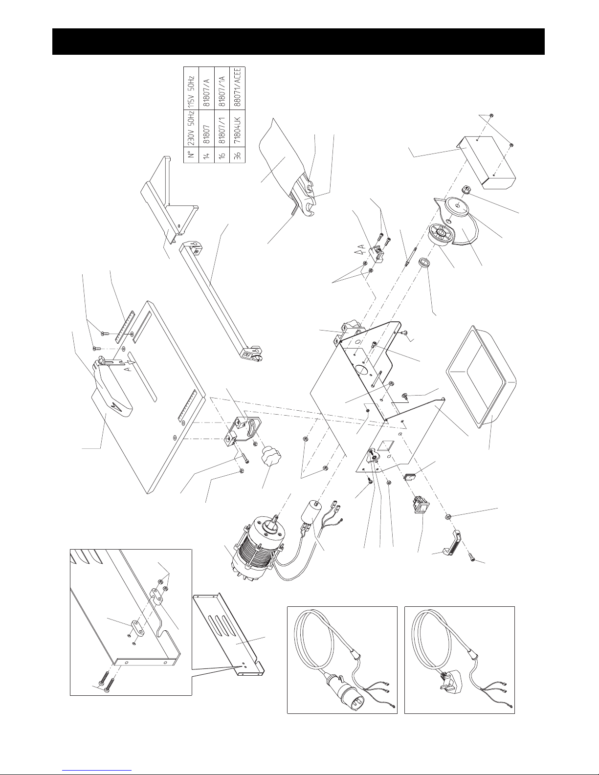
36
Minitile 180
36
46
31
15
48
49
4
34
33
32
36
8
47
22
25
35
23
24
40
7
20
18
19
21
30
4
29
28
27
26
39
2
3
5
6
38
37
12
1
16
04
14
10
11
09
17
43
41
42
45
13
15
ACEE
UK
Page 37

37
ITEM PART
NUMBER
(1)
NUMBER
(2)
DESCRIPTION
(3)
1 156.0.006 WORKING TABLE
2 156.0.007 SCREW (M6 X 16)
3 156.0.008 SCALE MEASUREMENT
4 156.0.046 NUT (M5)
5 156.0.045 DIAGONAL FENCE
6 156.0.009 CUTTING LINE
7 156.0.010 RIGHT EAR
8 156.0.011 AUTOFIXING NUT (M5)
9 156.0.047 NUT (M6)
10 156.0.012 KNOB
11 156.0.013 LEFT EAR
12 156.0.034 DISC GUARD
13 156.0.014 POSTERIOR COVER
14 156.0.036 ELECTRIC MOTOR (115V 50HZ)
14 156.0.035 ELECTRIC MOTOR (230V 50HZ)
15 8/8001 NUT (M8)
16 156.0.038 CAPACITOR (115V)
16 156.0.037 CAPACITOR (230V)
17 156.0.056 SCREW (M5 X 20)
18 156.0.039 DISC GUARD SUPPORT BRACKET
19 156.0.049 SCREW (M5 X 16)
20 156.0.015 FLANGED NUT (M5)
21 156.0.016 INTERIOR SUPPORT BOLT
22 156.0.040 SCREW (M6 X 8)
23 156.0.017 ROUND HEAD SCREW (M6 X 16)
24 156.0.018 EXTERNAL BODY
25 156.0.019 V SEAL
26 156.0.041 INTERNAL FLANGE
27 156.0.020 DIAMOND DISC (180MM X 25MM BORE)
28 156.0.042 EXTERNAL FLANGE
29 8/12002 NUT (M12)
30 156.0.021 INTERIOR PROTECTION DISC
31 156.0.022 WATER TANK
32 156.0.050 SCREW (M8 X 12)
33 156.0.051 HANDLE
34 156.0.092 SWITCH - 110V
34 156.0.075 SWITCH - 230V
35 156.0.024 RAPID FIX SCREW
36 156.0.044 PLUG & CABLE - ACEE (110V)
36 156.0.052 PLUG & CABLE - UK (230V)
37 156.0.025 KEY BAG
38 156.0.026 HEXAGONAL KEY (M6)
39 156.0.027 SPANNER (M7 - M8)
40 156.0.028 SPANNER (M18-M19)
41 156.0.055 NUT (M4)
42 156.0.029 CABLE CLIP
43 156.0.030 CABLE BRACKET
45 156.0.031 SCREW (M4 X 25)
46 156.0.032 SWITCH SPACER
47 156.0.033 RUBBER FEET
48 156.0.053 SCREW (M5 X 10)
49 4/8006 WASHER (M8)
Minitile 180
(1)
Item Number /
numéro sur le schéma / número de la ilustración / número da ilustração / afbeeldingsnummer / tegningsnummeret / Teil-Nummer / numero dell’illustrazione
(2)
Part Number / Numéro de référence de la pièce / número de pieza / número da parte / stuknummer / Styknummer / Nummer auf der Abbildung / numero di parte
(3)
Description / Désignation / Descripción / Descrição / Omschrijving / Beskrivelse / Bezeichnung / Descrizione
Page 38
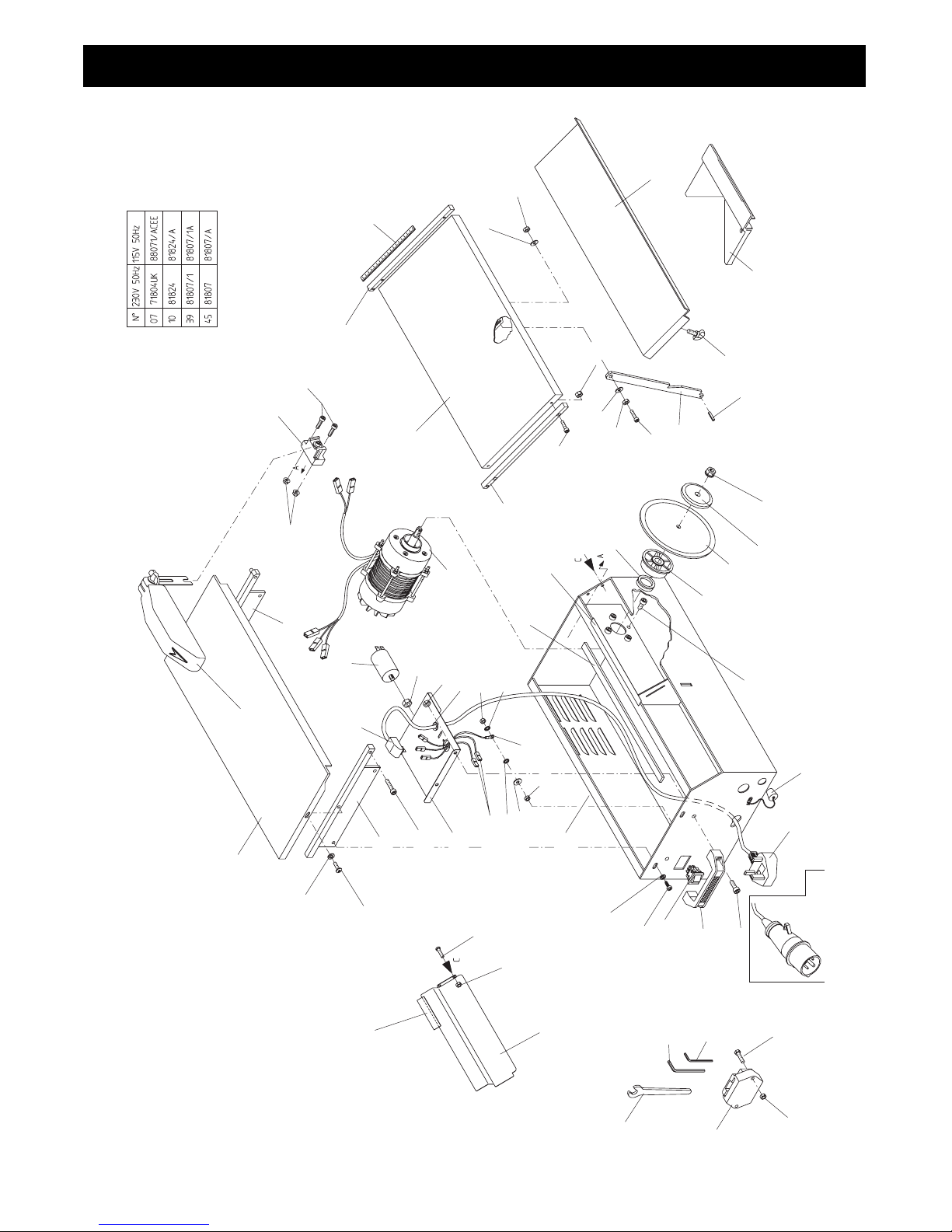
38
Minitile 200
16
9
10
11
12
14
13
17
18
15
8
19
5
7
6
21
26
23
221421
14
20
44
56
39
24
45
46
49
51
52
53
54
58
1
2
3
47
48
10
4
27
57
32
31
30
29
28
34
33
35
12
36
40
25
38
37
55
52
51
50
43
42
41
ACEE
7
14
Page 39

39
ITEM PART
NUMBER
(1)
NUMBER
(2)
DESCRIPTION
(3)
1 8/12002 NUT (M12)
2 156.0.042 EXTERNAL FLANGE
3 156.0.057 DIAMOND DISC (200MM X 25MM BORE)
4 156.0.041 INTERNAL FLANGE
5 156.0.040 SCREW (M6 X 8)
6 156.0.074 DRAIN PLUG
7 156.0.044 PLUG & CABLE - ACEE (110V)
7 156.0.052 PLUG & CABLE - UK (230V)
8 156.0.050 SCREW (M8 X 12)
9 156.0.051 HANDLE
10 156.0.092 SWITCH (115V)
10 156.0.075 SWITCH (230V)
11 156.0.076 SCREW (M6 X 10)
12 4/6001 WASHER (M6)
13 156.0.078 SCREW (M5 X 20)
14 156.0.046 NUT (M5)
15 156.0.069 TOOL HOLDER
16 156.0.070 HEXAGONAL KEY (M19)
17 156.0.079 HEXAGONAL KEY (M3)
18 156.0.110 HEXAGONAL KEY (M5)
19 156.0.061 STEEL BODY
20 156.0.080 EARTH LEAD
21 4/8006 WASHER (M8)
22 156.0.081 CABLE INSERT
23 8/8001 NUT (M8)
24 8/8001 NUT (M8)
25 156.0.082 TERMINAL BLOCK
26 156.0.083 WASHER (M5)
27 156.0.084 POWER CABLE
28 156.0.085 INTERNAL BASE PLATE
29 156.0.086 SCREW (M6 X 25)
30 156.0.072 LH SUPPORT - MOBILE TABLE
31 156.0.053 SCREW (M5 X 10)
32 156.0.093 SCREW (M4 X 6)
33 156.0.055 NUT M4
34 156.0.062 STEEL PROTECTION DISC
35 156.0.087 WATER SPRAY PROTECTOR
36 156.0.063 WORKING TABLE
37 156.0.034 DISC GUARD
38 156.0.071 RH SUPPORT - MOBILE TABLE
39 156.0.038 CAPACITOR (115V)
39 156.0.037 CAPACITOR (230V)
40 156.0.046 NUT (M5)
41 156.0.039 DISC GUARD SUPPORT BRACKET
42 156.0.049 SCREW (M5 X 16)
43 156.0.062 STEEL PROTECTION DISC
44 156.0.065 MOBILE TABLE
45 156.0.036 ELECTRIC MOTOR (115V 50HZ)
45 156.0.035 ELECTRIC MOTOR (230V 50HZ)
46 156.0.066 LATERAL THREADED MOBILE SUPPORT
47 156.0.073 WASHER
48 156.0.087 WATER SPRAY PROTECTOR
49 156.0.049 SCREW (M5 X 16)
50 156.0.088 SCALE MEASUREMENT
51 156.0.089 WASHER
52 156.0.047 NUT (M6)
53 156.0.090 SCREW (M6 X 22)
54 156.0.067 SUPPORT ROD - MOBILE TABLE
55 156.0.068 MOBILE TABLE EXTENSION
56 156.0.091 WING NUT
57 156.0.045 DIAGONAL FENCE
58 156.0.118 RUBBER PIN
59 156.0.019 V SEAL
Minitile 200
(1)
Item Number /
numéro sur le schéma / número de la ilustración / número da ilustração / afbeeldingsnummer / tegningsnummeret / Teil-Nummer / numero dell’illustrazione
(2)
Part Number / Numéro de référence de la pièce / número de pieza / número da parte / stuknummer / Styknummer / Nummer auf der Abbildung / numero di parte
(3)
Description / Désignation / Descripción / Descrição / Omschrijving / Beskrivelse / Bezeichnung / Descrizione
Page 40
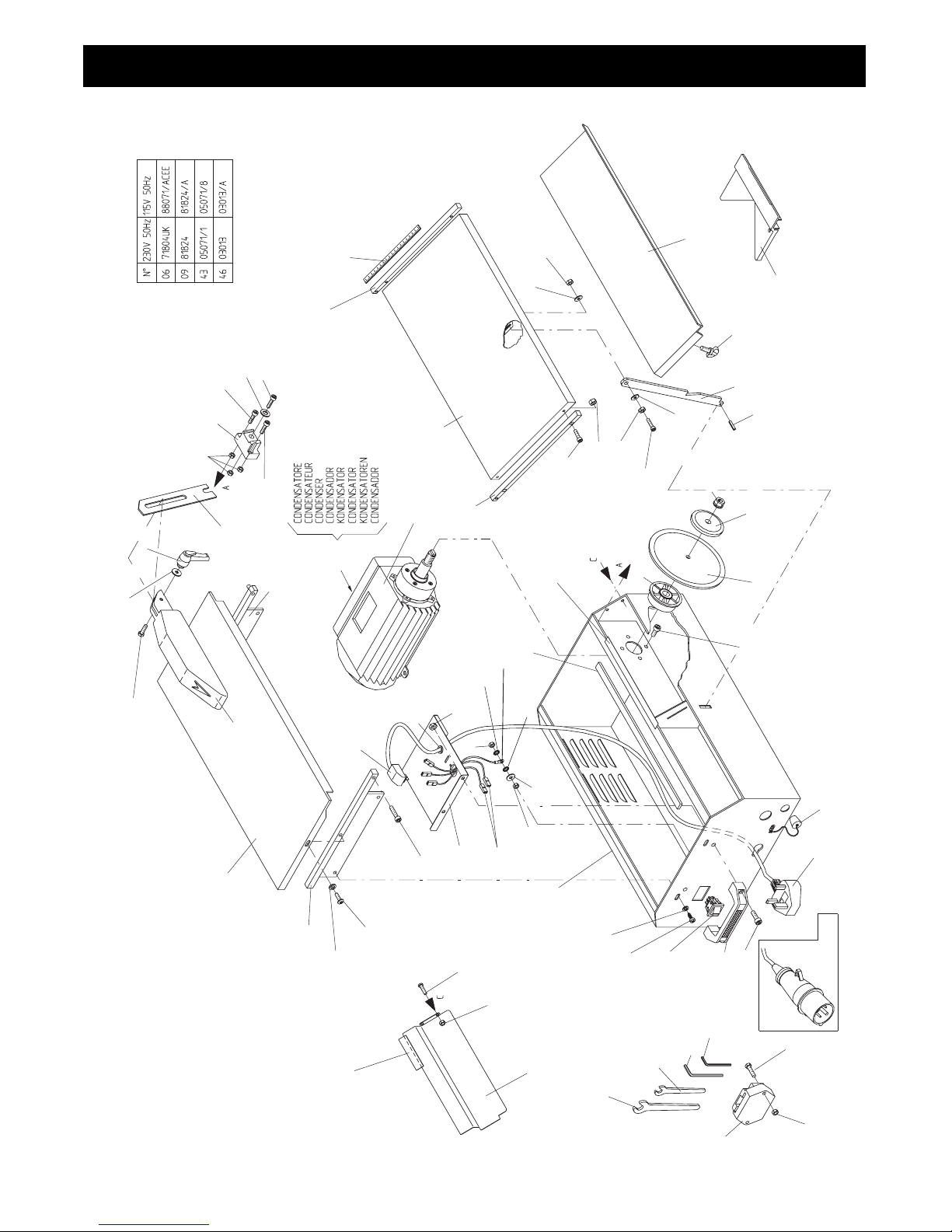
40
Minitile 230
51
61
19
11
10
9
17
18
16
15
60
59
20
31
11
30
29
28
27
13
50
22
23
21
21
24
25
26
13
40
39
13
43
37
36
35
38
34
32
33
46
42
41
40
35
40
48
47
45
44
35
52
53
49
13
49
02
01
57
56
55
58
54
04
03
6
14
13
12
6
8
7
5
ACEE
Page 41

41
ITEM PART
NUMBER
(1)
NUMBER
(2)
DESCRIPTION
(3)
1 8/12002 NUT (M12)
2 156.0.042 EXTERNAL FLANGE
3 156.0.058 DIAMOND DISC 230MM X 25MM BORE
4 156.0.096 SCREW (M6 X 12)
5 156.0.074 DRAIN PLUG
6 156.0.044 PLUG & CABLE - ACEE (110V)
6 156.0.052 PLUG & CABLE - UK (230V)
7 156.0.050 SCREW (M8 X 12)
8 156.0.051 HANDLE
9 156.0.092 SWITCH (115V)
9 156.0.075 SWITCH (230V)
10 156.0.076 SCREW (M6 X 10)
11 4/6001 WASHER (M6)
12 156.0.078 SCREW (M5 X 20)
13 156.0.046 NUT (M5)
14 156.0.069 TOOL HOLDER
15 156.0.070 HEXAGONAL KEY (M19)
16 156.0.097 SPANNER (7MM)
17 156.0.079 HEXAGONAL KEY (M3)
18 156.0.110 HEXAGONAL KEY (M5)
19 156.0.098 STEEL BODY
20 156.0.083 WASHER (M5)
21 4/8006 WASHER (M8)
22 156.0.073 WASHER
23 156.0.080 EARTH LEAD
24 8/8001 NUT (M8)
25 156.0.081 CABLE INSERT
26 156.0.082 TERMINAL BLOCK
27 156.0.084 POWER CABLE
28 156.0.085 INTERNAL BASE PLATE
29 156.0.086 SCREW (M6 X 25)
30 156.0.053 SCREW (M5 X 10)
31 156.0.072 LH SUPPORT - MOBILE TABLE
32 156.0.099 WORKING TABLE
33 156.0.100 DISC GUARD
34 156.0.111 SCREW (M6 X 20)
35 156.0.089 WASHER
36 156.0.112 LEVER
37 156.0.101 DISC GUARD SUPPORT
38 156.0.071 RH SUPPORT - MOBILE TABLE
39 156.0.102 DISC GUARD SUPPORT BRACKET
40 156.0.049 SCREW (M5 X 16)
41 156.0.103 WASHER (M5 X 15)
42 156.0.056 SCREW (M5 X 20)
43 156.0.105 CAPACITOR (115V)
43 156.0.104 CAPACITOR (230V)
44 156.0.113 RH LATERAL MOBILE SUPPORT
45 156.0.088 SCALE MEASUREMENT
46 156.0.107 MOTOR (115V 50HZ)
46 156.0.106 MOTOR (230V 50HZ)
47 156.0.108 MOBILE TABLE
48 156.0.114 LH LATERAL MOBILE SUPPORT
49 156.0.047 NUT (M6)
50 156.0.087 WATER SPRAY PROTECTOR
51 156.0.087 WATER SPRAY PROTECTOR
52 156.0.041 INTERNAL FLANGE
53 156.0.090 SCREW (M6 X 22)
54 156.0.116 MOBILE TABLE EXTENSION
55 156.0.091 WING NUT
56 156.0.117 MOBILE TABLE SUPPORT ROD
57 156.0.118 RUBBER PIN
58 156.0.045 DIAGONAL FENCE
59 156.0.062 STEEL PROTECTION DISC
60 156.0.055 NUT (M4)
61 156.0.093 SCREW (M4 X 6)
Minitile 230
(1)
Item Number /
numéro sur le schéma / número de la ilustración / número da ilustração / afbeeldingsnummer / tegningsnummeret / Teil-Nummer / numero dell’illustrazione
(2)
Part Number / Numéro de référence de la pièce / número de pieza / número da parte / stuknummer / Styknummer / Nummer auf der Abbildung / numero di parte
(3)
Description / Désignation / Descripción / Descrição / Omschrijving / Beskrivelse / Bezeichnung / Descrizione
Page 42
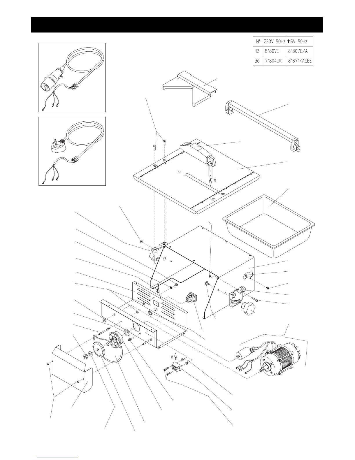
42
Magiktile 180
37
35
34
5
1
2
4
3
9
8
7
6
17
16
15
14
32
13
12
10
24
28
27
26
25
24
23
22
21
20
19
18
33
28
29
31
30
36
36
UK
ACEE
Page 43

43
ITEM PART
NUMBER
(1)
NUMBER
(2)
DESCRIPTION
(3)
1 156.0.045 DIAGONAL FENCE
2 156.0.225 SLIDING GUIDE
3 156.0.034 DISC GUARD
4 156.0.226 CUTTING TABLE
5 156.0.227 WATER TANK
6 156.0.228 MAIN BODY
7 156.0.229 NUT
8 156.0.230 SCREW
9 156.0.010 RIGHT EAR
10 156.0.056 SCREW (M5 X 20)
11 156.0.012 KNOB
12 156.0.239 MOTOR ASSEMBLY (115V)
12 156.0.231 MOTOR ASSEMBLY (230V)
13 156.0.017 ROUND HEAD SCREW (M6 X 16)
14 156.0.232 CABLE RETAINING NUT
15 156.0.015 FLANGED NUT (M5)
16 156.0.039 DISC GUARD SUPPORT BRACKET
17 156.0.049 SCREW (M5 X 16)
18 156.0.040 SCREW (M6 X 8)
19 156.0.233 INTERNAL FLANGE
20 156.0.234 DIAMOND DISC (MAGIK 180)
21 156.0.235 EXTERNAL FLANGE
22 156.0.198 WASHER (12MM)
23 156.0.236 OUTER COVER
24 156.0.046 NUT (M5)
25 156.0.237 BLADE RETAINING NUT
26 156.0.016 INTERIOR SUPPORT BOLT
27 156.0.019 V SEAL
28 8/8001 NUT (M8)
29 4/8006 WASHER (M8)
30 156.0.238 MOTOR COVER
31 156.0.033 RUBBER FEET
32 156.0.023 SWITCH
33 156.0.013 LEFT EAR
34 156.0.047 NUT M6
35 156.0.011 AUTOFIXING NUT (M5)
36 156.0.044 PLUG & CABLE - ACEE (110V)
36 156.0.052 PLUG & CABLE - UK (230V)
37 156.0.007 SCREW (M6 X 16)
38 156.0.053 SCREW (M5 X 10)
Magiktile 180
(1)
Item Number /
numéro sur le schéma / número de la ilustración / número da ilustração / afbeeldingsnummer / tegningsnummeret / Teil-Nummer / numero dell’illustrazione
(2)
Part Number / Numéro de référence de la pièce / número de pieza / número da parte / stuknummer / Styknummer / Nummer auf der Abbildung / numero di parte
(3)
Description / Désignation / Descripción / Descrição / Omschrijving / Beskrivelse / Bezeichnung / Descrizione
Page 44
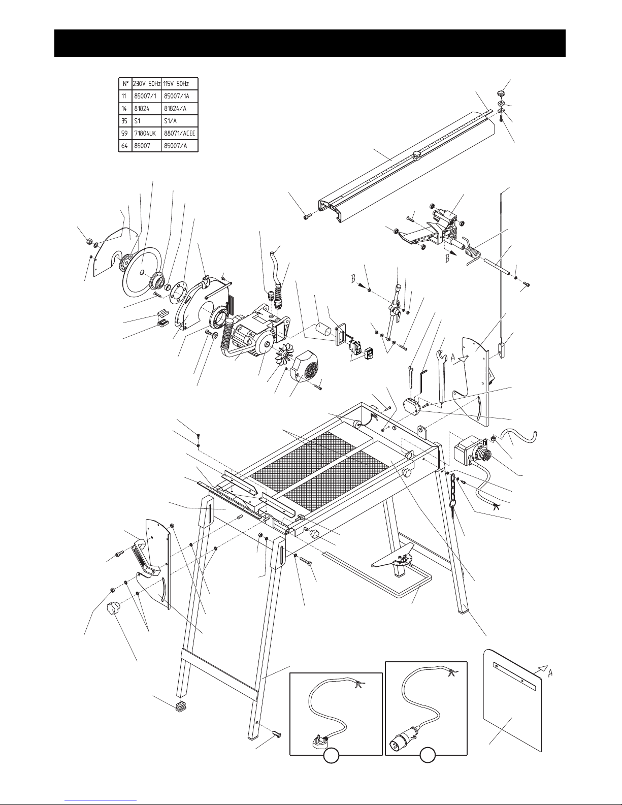
44
Maxitile 260
1
26
25
85
7
6
5
4
3
86
2
29
23
22
21
13
20
19
9
28
8
27
33
16
18
13
17
24
32
31
30
36
17
35
42
40
38
37
20
7
17
72
81
79
78
77
7
75
74
73
80
83
61
62
63
64
65
84
66
67
68
69
70
71
60
56
57
58
17
36
82
15
14
12
11
10
45
27
27
53
54
43
44
55
39
47
48
51
27
50
49
27
48
46
52
41
34
53
59
59
UK
ACEE
Page 45

45
ITEM PART
NUMBER
(1)
NUMBER
(2)
DESCRIPTION
(3)
1 156.0.145 KNOB
2 156.0.146 LOCKING (ABOVE INDICATOR)
3 156.0.147 LOCKING (BELOW INDICATOR)
4 156.0.111 SCREW (M6 X 20)
5 156.0.148 ROD WATER PIPE
6 156.0.149 ENGINE SLIDE
7 156.0.150 SCREW (M6 X 25)
8 156.0.151 BEARING
9 8/6001 NUT (M6)
10 156.0.153 SWITCH MOUNTING PLATE
11 156.0.155 CAPACITOR (115V)
11 156.0.154 CAPACITOR (230V)
12 156.0.156 SCREW (M4 X 12)
13 156.0.157 AUTOFIXING NUT (M6)
14 156.0.092 SWITCH & COVER (115V)
14 156.0.075 SWITCH & COVER (230V)
15 156.0.158 SCREW (M5 X 25)
16 156.0.159 SCREW RIVETS (9X9)
17 156.0.015 FLANGED NUT (M5)
18 156.0.160 PLASTIC WASHER
19 156.0.161 STOP/RUN LEVER COMPLETE
20 4/6001 WASHER (M6)
21 156.0.162 SCREW (M6 X 30)
22 156.0.163 8MM WRENCH
23 156.0.110 HEXAGONAL KEY (M5)
24 156.0.070 HEXAGONAL KEY (M19)
25 156.0.164 TORSION SPRING
26 156.0.165 FULCRUM PIN
27 4/8006 WASHER (M8)
28 156.0.166 SCREW (M8 X 10)
29 156.0.167 LEFT BRACKET
30 156.0.168 WATER PIPE ROD HOLDER
31 156.0.078 SCREW (M5 X 20)
32 156.0.069 TOOL HOLDER
33 156.0.169 WATER PIPE (9X6)
34 156.0.170 METAL WASHER (9X6)
35 156.0.172 WATER PUMP (115V)
35 156.0.171 WATER PUMP (230V)
36 156.0.184 SCREW (M5 X 8)
37 156.0.209 LEG FIXING PIN
38 156.0.210 WORKING TABLE
39 156.0.224 RUBBER PAD
40 156.0.211 INTERNAL LEG
41 156.0.177 WATER SPRAY PROTECTION
42 156.0.176 DIAGONAL FENCE COMPLETE
43 156.0.174 KNOB
44 156.0.175 KNOB
45 156.0.213 SCREW (M8 X 40)
46 156.0.214 BUSH TO FIT LEGS
47 156.0.215 SCREW PLUG
48 156.0.180 AUTOFIXING NUT (M8)
49 8/8001 NUT (M8)
50 156.0.178 RH BRACKET
51 156.0.179 KNOB
52 156.0.216 EXTERNAL LEG
53 156.0.050 SCREW (M8 X 12)
54 156.0.051 HANDLE
55 156.0.217 STEEL BODY
56 156.0.088 SCALE MEASUREMENT
57 156.0.182 RIGHT TILE SUPPORT
58 156.0.183 LEFT TILE SUPPORT
Maxitile 260
(1)
Item Number /
numéro sur le schéma / número de la ilustración / número da ilustração / afbeeldingsnummer / tegningsnummeret / Teil-Nummer / numero dell’illustrazione
(2)
Part Number / Numéro de référence de la pièce / número de pieza / número da parte / stuknummer / Styknummer / Nummer auf der Abbildung / numero di parte
(3)
Description / Désignation / Descripción / Descrição / Omschrijving / Beskrivelse / Bezeichnung / Descrizione
ITEM PART
NUMBER
(1)
NUMBER
(2)
DESCRIPTION
(3)
59 156.0.044 PLUG & CABLE (110V)
156.0.052 PLUG & CABLE (230V)
60 156.0.074 DRAIN PLUG
61 156.0.186 MOTOR FAN COVER
62 156.0.046 NUT (M5)
63 156.0.187 MOTOR COOLING FAN
64 156.0.189 MOTOR (115V 50HZ)
156.0.188 MOTOR (230V 50HZ)
65 156.0.190 WORKING HANDLE
66 156.0.191 WASHER (6 X 24)
67 156.0.192 RAPID FIXING SCREW
68 156.0.193 SPACER
69 156.0.194 DISC GUARD
70 156.0.195 SPRAY (FEMALE)
71 156.0.196 SPRAY (MALE)
72 8/12003 NUT (M12 L/H)
73 156.0.198 WASHER (12MM)
74 156.0.199 EXTERIOR DISC GUARD COVER
75 156.0.042 EXTERNAL FLANGE
76 156.0.057 DIAMOND DISC
77 156.0.041 INTERNAL FLANGE
78 156.0.019 V SEAL
79 156.0.200 SPACER
80 156.0.201 CABLE STOP
81 156.0.202 VALVE
82 156.0.203 SCREW 5 X 30
83 156.0.204 CABLE PUMP PROTECTION
84 156.0.205 CABLE STOP
85 156.0.222 RAIL
86 156.0.223 SCALE MEASUREMENT
Page 46

46
Belle Group Head Office
Sheen, nr. Buxton
Derbyshire. SK17 OEU GB.
Tel: +44 (0)1298 84000
Fax: +44 (0)1298 84722
email: [email protected]
Belle Group France
70, av du Général de Gaulle
94022 Creteil, Cedex.
FRANCE
Tel: +33 (0) 1 49 81 68 32
Fax: +33 (0) 1 43 39 94 40
Ventes : 0800 902 461
SAV : 0800 905 336
SAV Fax : 0800 909 895
Belle Equipos SL
Calle Doctor Calero Cial 19,
Local 22, 28220 Majadahonda
Madrid, Spain
Tel: +34 (0) 91 636 2043
Fax: +34 (0) 91 634 1535
email:[email protected]
Belle Group Deutschland
Husumer Straße 45 a,
D-33729,
Bielefield
Deutschland
Tel : +49(0) 5217 707505
Fax : +49 (0) 5217 707506
Sales: 0800 1808069
Spares: 0800 1816673
Belle Group (GB), Shanghai Office
Room 213, Zhonghuang Building,
1007 Zhongshan Nan Er Road,
Xuhui, Shanghai 200030 China
Tel: 00 - 86 - 21 - 5461 5228
Mobile: 00 - 86 - 133 8172 2653
Fax: 00 - 86 - 21 - 5461 5369
email: [email protected]
Belle Group Inc
3959 Electric Rd
Roanoake
Suite 360
VA 24018. USA.
Tel: +1.540.345.5090
Fax: +1.540.345.5091
Toll free 866 540 5090
e-mail: [email protected]
Belle Group World Parts Centre
Unit 5, Bode Business Park
Ball Haye Green,
Leek,
Staffordshire,
ST13 8BW
Tel: 44+ 1538 380000
Fax: 44+ 1538 380038
Belle Poland sp. z.o.o.
96-200 Rawa Mazowiecka
Ul. Mszczonowska 36,
Polska
Tel: +48 (0) 46 8144091
Fax: +48 (0) 46 8144700
Belle Group Portugal
Rua Laura Alves, 225, 2° F
2775-116 Parede
Portugal
Tel: +35 1 (21) 453 59 91
Fax: +35 1 (21) 453 59 91
Belle Group Netherlands
Tel: 0800 249861
Belle Group Belguim
Tel: 0800 80295
Belle Group Austria
Tel: 0800 291544
Belle Group Russia
64 Nevsky pr.
St, Petersburg
Russia
Tel : +7(812)314-81-34
Moscow : +7(495)589-64-32
Belle Group South East Asia
21, Jalan Ara AD 7/3B,
Pandar Sri Damansara
S2200 Kuala Lumpar, Malaysia
Tel: +60 (0) 3 62721678
+60 (0) 3 6272 9308
Fax: +60 (0) 3 6272 9528
No.1 for Light Construction Equipment
www.BelleGroup.com
COMPACTING... MIXING... CONCRETING... CUTTING... BREAKING... MOVING
No.1 for Light Construction Equipment
www.BelleGroup.com
 Loading...