

Page 1

STS T10
s.r.l.
D22002300 ver.0 - UPD 180612 - © 2012 BELL
MANUALE DI USO E MANUTENZIONE
MANUAL FOR USE AND MAINTENANCE
WARTUNGS- UND BETRIEBSANLEITUNGEN
LIVRET D'EMPLOI ET D'ENTRETIEN
Page 2
1
s.r.l.
2
3
5a 5b
4
2
D22002300 v.0 - UPD 180612
Page 3
6a 6b
6c
6d
s.r.l.
7a 7b
7c 7d
D22002300 v.0 - UPD 180612
3
Page 4

s.r.l.
8a 8b
8c
8d 8e
9a 9b
4
D22002300 v.0 - UPD 180612
Page 5
10
AB
s.r.l.
11
C
D
12a
12b
D22002300 v.0 - UPD 180612
5
Page 6

s.r.l.
INDICE GENERALE
INTRODUZIONE .......................................................................................................................................................................................................................................8
1 DESCRIZIONE DELLA MACCHINA ........................................................................................................................................................................................................8
1.1 Iconografi a .....................................................................................................................................................................................................................................9
2 CARATTERISTICHE TECNICHE ...........................................................................................................................................................................................................10
2.1 Corretto modo per sollevare la macchina ....................................................................................................................................................................................10
2.2 Dimensioni del legno da rompere ................................................................................................................................................................................................10
2.3 Olii consigliati ...............................................................................................................................................................................................................................10
3 SICUREZZA ............................................................................................................................................................................................................................................10
3.1 Regole generali di sicurezza .......................................................................................................................................................................................................11
3.1.A Per macchine con motore elettrico (STS T10 E - STS T10 T) .....................................................................................................................................................11
3.1.B Per macchine azionate da albero cardanico (STS T10 GC) .......................................................................................................................................................11
4 MESSA IN FUNZIONE ............................................................................................................................................................................................................................12
4.1.A Per macchine con motore elettrico trifase (STS T10 T)...............................................................................................................................................................12
4.1.B Per macchine azionate da albero cardanico (STS T10 GC) .......................................................................................................................................................12
4.2.A Abbassare il piano di raccolta legno ............................................................................................................................................................................................13
4.2.B Sollevare il piano di appoggio legno ............................................................................................................................................................................................13
4.2.C Regolazione dell'altezza della lama ............................................................................................................................................................................................13
4.3 Illuminazione ................................................................................................................................................................................................................................13
5 USO .....................................................................................................................................................................................................................................................13
5.1.A Accensione e spegnimento dello spaccalegna elettrico (STS T10 E - STS T10 T) .....................................................................................................................13
5.1.B Accensione e spegnimento degli spaccalegna azionati da trattore (STS T10 GC) ..................................................................................................................... 13
5.2 Uso dello spaccalegna ................................................................................................................................................................................................................14
5.3 Movimentazione dello spaccalegna .............................................................................................................................................................................................14
6 MANUTENZIONE ORDINARIA ..............................................................................................................................................................................................................15
6.1 Sostituzione dell'olio idraulico ......................................................................................................................................................................................................15
6.2 Affi latura della lama .....................................................................................................................................................................................................................15
7 INCONVENIENTI E RIMEDI ...................................................................................................................................................................................................................15
7.1 Disincastro del legno bloccato (fi g.10, pag.5) ..............................................................................................................................................................................15
7.2 Ricerca e soluzione dei problemi .................................................................................................................................................................................................16
7.3 Riarmo della protezione termica del motore elettrico ..................................................................................................................................................................16
DEMOLIZIONE E SMALTIMENTO DELLA MACCHINA .......................................................................................................................................................................16
GARANZIA .............................................................................................................................................................................................................................................17
PARTI DI RICAMBIO ..............................................................................................................................................................................................................................48
ATTENZIONE
All'atto della consegna della macchina assicuratevi che non vi siano parti mancanti o danneggiate durante il trasporto. Eventuali reclami devono essere
notifi cati immediatamente al trasportatore e al rivenditore. Non verranno riconosciuti reclami postumi.
INDEX
INTRODUCTION .....................................................................................................................................................................................................................................18
1 DESCRIPTION OF THE MACHINE ........................................................................................................................................................................................................18
1.1 Symbols used ..............................................................................................................................................................................................................................19
2 TECHNICAL DATA .................................................................................................................................................................................................................................20
2.1 Right way to lift the machine ........................................................................................................................................................................................................20
2.2 Size of the logs to be split ............................................................................................................................................................................................................20
2.3 Recommended oils ......................................................................................................................................................................................................................20
3 SAFETY ..................................................................................................................................................................................................................................................20
3.1 General safety regulations ...........................................................................................................................................................................................................21
3.1.A For machines with electric motor (STS T10 E - STS T10 T) ......................................................................................................................................................21
3.1.B For machines driven by cardan shaft (STS T10 GC) ..................................................................................................................................................................21
4 OPERATING THE MACHINE .................................................................................................................................................................................................................22
4.1.A For machines with 3-phase electric motor (STS T10 T) ..............................................................................................................................................................22
4.1.B For machines driven by cardan shaft (STS T10 GC) ..................................................................................................................................................................22
4.2.A How to lower the log collection plate ...........................................................................................................................................................................................23
4.2.B How to lift the log support plate ...................................................................................................................................................................................................23
4.2.C Regulation of the wedge height ...................................................................................................................................................................................................23
4.3 Lighting ........................................................................................................................................................................................................................................23
5 USE 23
5.1.A Switching on/off of the machine with electric motor (STS T10 E - STS T10 T) ...........................................................................................................................23
5.1.B Switching on/off of the machine driven by cardan shaft (STS T10 GC) ......................................................................................................................................23
5.2 How to use the log-splitter ...........................................................................................................................................................................................................24
5.3 Moving the log splitter ..................................................................................................................................................................................................................24
6 ROUTINE MAINTENANCE ....................................................................................................................................................................................................................25
6.1 How to change the hydraulic oil ...................................................................................................................................................................................................25
6.2 Sharpening the wedge .................................................................................................................................................................................................................25
7 TROUBLESHOOTING ............................................................................................................................................................................................................................25
7.1 How to free a jammed log (fi g.10, page 5) ..................................................................................................................................................................................25
7.2 Troubleshooting ...........................................................................................................................................................................................................................26
7.3 Resetting of the thermal cut-out of the electric motor ..................................................................................................................................................................26
SCRAPPING AND DISPOSAL OF THE MACHINE ...............................................................................................................................................................................26
GUARANTEE .........................................................................................................................................................................................................................................27
SPARE PARTS .......................................................................................................................................................................................................................................48
WARNING
When the machine is delivered, check for any missing parts and for any damage during transport. Any complaints must be forwarded immediately to
the carrier and to the retailer. Any subsequent complaints will not be accepted.
6
D22002300 v.0 - UPD 180612
Page 7

ALLGEMEINES INHALTSVERZEICHNIS
EINLEITUNG ..........................................................................................................................................................................................................................................28
1 MASCHINENBESCHREIBUNG .............................................................................................................................................................................................................28
1.1 Aufschlüsselung der Warnhinweise .............................................................................................................................................................................................29
2 TECHNISCHE EIGENSCHAFTEN .........................................................................................................................................................................................................30
2.1 Richtige Weise, um die Maschine zu heben ................................................................................................................................................................................30
2.2 Maße des Spaltklotzes ................................................................................................................................................................................................................30
2.3 Empfohlene Ölsorten ...................................................................................................................................................................................................................30
3 SICHERHEIT ..........................................................................................................................................................................................................................................30
3.1 Allgemeine Sicherheitsvorschriften .............................................................................................................................................................................................31
3.1.A Für Maschinen mit Elektromotor (STS T10 E - STS T10 T) ........................................................................................................................................................31
3.1.B Für Maschinen mit Kardanwellenantrieb (STS T10 GC) .............................................................................................................................................................31
4 INBETRIEBSETZUNG ............................................................................................................................................................................................................................32
4.1.A Für Maschinen mit Elektromotor (STS T10 T) .............................................................................................................................................................................32
4.1.B Für Maschinen mit Kardanwellenantrieb (STS T10 GC) .............................................................................................................................................................32
4.2.A Holzsammelfl äche absenken .......................................................................................................................................................................................................33
4.2.B Holzhalterungsfl äche anheben ....................................................................................................................................................................................................33
4.2.C Betätigung der Messerhöhe ........................................................................................................................................................................................................33
4.3 Beleuchtung .................................................................................................................................................................................................................................33
5 EINSATZ DES HOLZSPALTERS ...........................................................................................................................................................................................................33
5.1.A Zu- und Abschalten des Elektrischen Holzspalters (STS T10 E - STS T10 T) ............................................................................................................................33
5.1.B Zu- und Abschalten der Holzspalter mit Schlepperantrieb (STS T10 GC) ..................................................................................................................................33
5.2 Verwendung des Holzspalters .....................................................................................................................................................................................................34
5.3 Bewegung des Holzspalters ........................................................................................................................................................................................................34
6 REGELMÄSSIGE WARTUNG ................................................................................................................................................................................................................35
6.1 Wechsel des Hydrauliköls ...........................................................................................................................................................................................................35
6.2 Schleifen des Messers ................................................................................................................................................................................................................35
7 STÖRUNGEN UND DEREN BEHEBUNG .............................................................................................................................................................................................35
7.1 Befreien des blockierten Holzstückes (Abb.10, Seite 5) ..............................................................................................................................................................35
7.2 Störungssuche und deren Abhilfen ..............................................................................................................................................................................................36
7.3 Rückstellen des Thermoschutzes des E-Motors .........................................................................................................................................................................36
VERSCHROTTUNG UND ENTSORGUNG DER MASCHINE ...............................................................................................................................................................36
GARANTIE .............................................................................................................................................................................................................................................37
ERSATZTEILE ........................................................................................................................................................................................................................................48
s.r.l.
ACHTUNG
Die Maschine ist sofort nach der Entgegennahme auf Fehlen von Teilen oder Transportschäden zu überprüfen. Etwaige Beanstandungen sind unverzüglich beim Spediteur oder beim Wiederverkäufer vorzubringen. Nachträgliche Beanstandungen werden nicht in Betracht gezogen.
INDEX
INTRODUCTION .....................................................................................................................................................................................................................................38
1 DESCRIPTION DE LA MACHINE ..........................................................................................................................................................................................................38
1.1 Iconographie ................................................................................................................................................................................................................................39
2 CARACTERISTIQUES TECHNIQUES ...................................................................................................................................................................................................40
2.1 Correct maniere pour soulever la machine .................................................................................................................................................................................40
2.2 Dimensions du bois à débiter ......................................................................................................................................................................................................40
2.3 Huiles conseillées ........................................................................................................................................................................................................................40
3 SECURITE ..............................................................................................................................................................................................................................................40
3.1 Règles générales de sécurité ......................................................................................................................................................................................................41
3.1.A Pour les machines équipées d’un moteur électrique (STS T10 E - STS T10 T) .........................................................................................................................41
3.1.B Pour machines actionnées par un joint de Cardan (STS T10 GC) ..............................................................................................................................................41
4 MISE EN MARCHE .................................................................................................................................................................................................................................42
4.1.A Pour les machines équipées d’un moteur électrique triphasée (STS T10 T) ..............................................................................................................................42
4.1.B Pour machines actionnées par un joint de Cardan (STS T10 GC) ..............................................................................................................................................42
4.2.A Abaisser le plateau pour la réception du bois ..............................................................................................................................................................................43
4.2.B Soulever le plateau appui tronc ...................................................................................................................................................................................................43
4.2.C Réglage de l'hauteur de la lame ..................................................................................................................................................................................................43
4.3 Éclairage ......................................................................................................................................................................................................................................43
5 MODE D’EMPLOI ...................................................................................................................................................................................................................................43
5.1.A Mise en marche et arrêt de la fendeuse de bois avec moteur électrique (STS T10 E - STS T10 T) ...........................................................................................43
5.1.B Mise en marche et arrêt de la fendeuse de bois actionnées par un joint de Cardan (STS T10 GC) ..........................................................................................43
5.2 Mode d’emploi de la fendeuse à bois ..........................................................................................................................................................................................44
5.3 Déplacement de la fendeuse de bois ..........................................................................................................................................................................................44
6 ENTRETIEN ORDINAIRE .......................................................................................................................................................................................................................45
6.1 Remplacement de l'huile hydraulique ..........................................................................................................................................................................................45
6.2 Affi lage de la lame .......................................................................................................................................................................................................................45
7 INCONVENIENTS ET SOLUTIONS .......................................................................................................................................................................................................45
7.1 Dégagement du bois encastré (fi g.10, page 5) ...........................................................................................................................................................................45
7.2 Petit guide de dépannage ............................................................................................................................................................................................................46
7.3 Réarmement de la protection thermique du moteur électrique ...................................................................................................................................................46
DEMANTELEMENT ET ELIMINATION DE LA MACHINE ....................................................................................................................................................................46
GARANTIE .............................................................................................................................................................................................................................................47
PIECES DE RECHANGE .......................................................................................................................................................................................................................48
ATTENTION
Au moment de la livraison de la machine veuillez vous assurer qu'il n'y à pas des parties manquantes ou dommagées pendant le transport. Eventuelles
réclamations doivent être notifi ées immediatement au transporteur et au revendeur. Réclamations tardives ne seront pas acceptées.
D22002300 v.0 - UPD 180612
7
Page 8

s.r.l.
ITALIANO
ISTRUZIONI ORIGINALI
INTRODUZIONE
Le macchine spaccalegna BELL® sono state progettate e costruite conformemente alle più recenti normative europee in fatto di sicurezza con particolare riferimento alle normative EN 609-1 e CEI EN 60204-1.
I sistemi di comando a due mani, infatti, sono stati studiati al fi ne di obbligare l’operatore a manovrare l'azionamento della macchina soltanto dalle
zone consentite, impiegando entrambe le mani ed escludendo ogni possibile intromissione degli arti in zone pericolose.
Questa macchina spaccalegna è prodotta conformemente alle prescrizioni contenute nella direttiva RoHS 2002/95/CE
Prima di movimentare, installare e rendere operativa la macchina, leggete attentamente questo manuale poichè vi sono contenute importanti
regole per lavorare in sicurezza.
Se l’operatore non fosse in grado di capire una delle lingue del presente libretto, sarà suo compito richiedere la traduzione nella propria lingua al
rivenditore.
L’operatore dovrà altresì addestrare ogni altra persona abilitata all’uso della macchina.
Ogni inosservanza, uso improprio della macchina, manutenzione straordinaria non effettuata da personale specializzato ed autorizzato,
la rimozione di etichette di ogni tipo, la rimozione o la manomissione delle protezioni e delle sicurezze e comunque ogni altra azione non
espressamente autorizzata volta ad infi ciare le sicurezze attive e passive della macchina fa decadere ogni responsabilità del costruttore e
può causare gravi danni alle persone e alle cose.
La manomissione della macchina da parte di personale non autorizzato fa decadere automaticamente la garanzia.
Il presente libretto è parte integrante della macchina e dovrà sempre accompagnarla anche in caso di passaggio di proprietà.
ATTENZIONE: Il sistema di alimentazione della vostra macchina, produce un campo elettromagnetico di intensità molto bassa. Questo
campo può interferire con alcuni pacemaker. Per ridurre il rischio di lesioni gravi o mortali, le persone con pacemaker dovrebbero consultare
il proprio medico e il costruttore del pacemaker prima di utilizzare questa macchina.
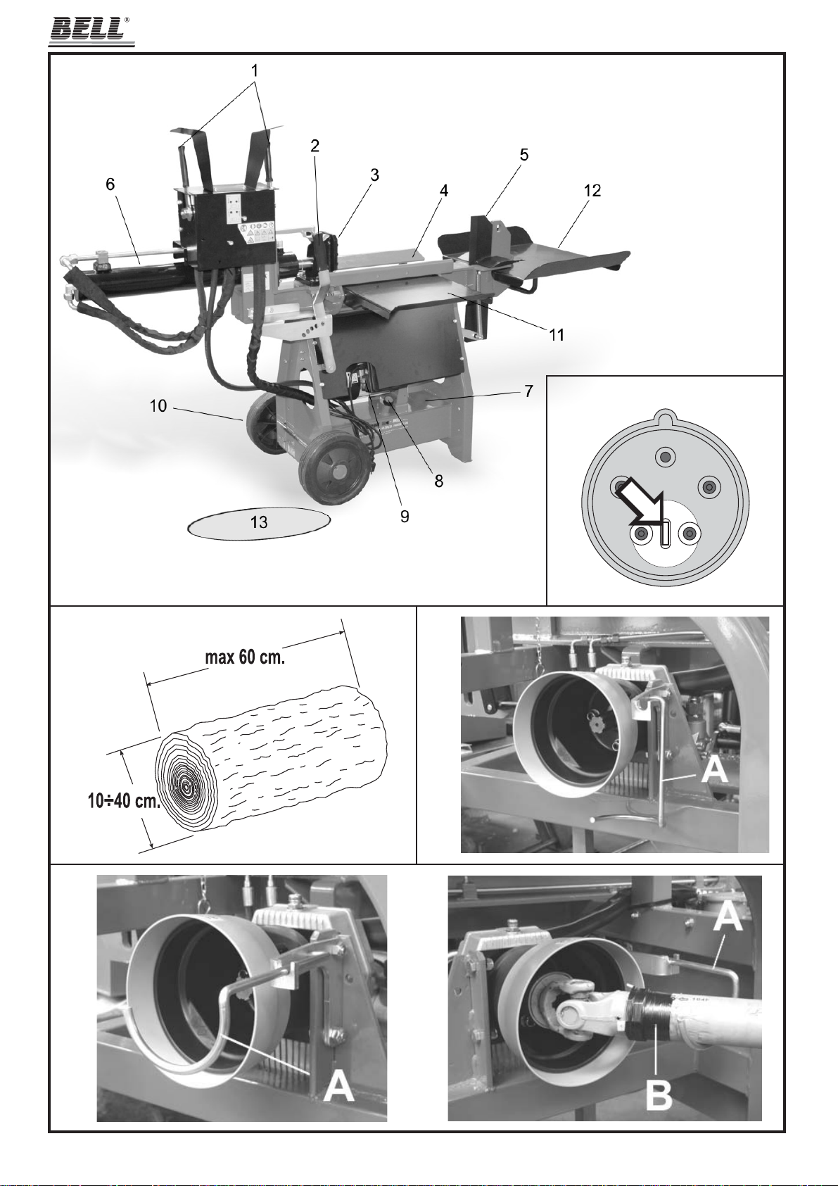
1 - DESCRIZIONE DELLA MACCHINA
Questa serie è formata da spaccalegna orizzontali trasportabili dotati di motorizzazione propria elettrica oppure di aggancio esterno per azionamento
da trattore. In fi g.1, pag. 2, sono illustrate le varie parti della macchina.
1 - Leve del comando ZHB
2 - Leva movimentazione lama
3 - Spingitronco
4 - Guide appoggia-tronco
5 - Lama
6 - Cilindro
7 - Serbatoio dell'olio
8 - Tappo riempimento olio
9 - Motore elettrico
10 - Ruote per piccoli spostamenti
11 - Piano appoggio legno
12 - Piano raccolta legno
13 - ZONA DI LAVORO CONSENTITA E OBBLIGATORIA
8
D22002300 v.0 - UPD 180612
Page 9
ITALIANO
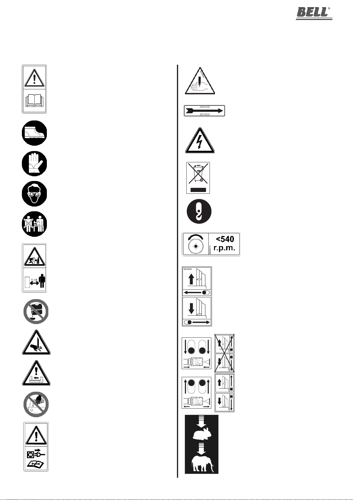
1.1 - Iconografi a
Sulla macchina sono riportate segnalazioni grafi che normalizzate al fi ne di garantire la massima sicurezza relativamente a tutte le parti dello spacca-
legna. Per l’importanza di tali segnalazioni vi preghiamo di leggere attentamente quanto segue.
Pericolo di taglio e schiacciamento della mano: non
Leggere attentamente l’intero libretto di uso e manutenzione della macchina prima della messa in funzione.
Al fi ne di evitare schiacciamenti dei piedi durante le
normali operazione di carico e scarico dei ceppi di
legno, è obbligatorio indossare adeguate calzature di
protezione.
Per riparare le mani da schegge di legno o urti contro
la macchina è obbligatorio indossare adeguati guanti
a protezione di entrambe le mani.
Per riparare gli occhi da schegge che possono prodursi
durante l'operazione di rottura del ceppo, è obbligatorio
indossare adeguati occhiali protettivi.
B93250240
toccare mai le zone a rischio durante il movimento
della lama.
Senso di rotazione del motore. In caso di rotazione
errata seguite le istruzioni riportate nel paragrafo
4.1.A a pag.12.
Pericolo: tensione elettrica come indicato da targhetta.
Le macchine dotate di apparecchiature elettriche non devono essere smaltite come rifi uti misti, ma attraverso una
raccolta differenziata separata, presso i punti autorizzati.
s.r.l.
Lo spaccalegna deve essere utilizzato da una sola
persona
É vietato sostare nel raggio di azione della macchina
quando questa è in moto. Nessuna persona o animale
può sostare in un raggio di cinque metri dalla macchina
durante il normale funzionamento della stessa.
É vietato scaricare l’olio esausto nell’ambiente.
L’olio deve essere smaltito secondo le leggi in vigore nel
paese in cui viene effettuata tale operazione.
Pericolo di taglio e schiacciamento della mano: non
toccare mai le zone a rischio durante il movimento
della lama.
Pericolo: attenzione al movimento dello spingitronco.
Punto di aggancio
Il senso di rotazione dell'albero del cardano
deve essere come indicato nell'etichetta e
non deve superare i 540 giri al minuto.
Azionamento dell'altezza della lama: spingendo la leva
verso sinistra, si alza la lama; azionando la leva verso
destra, la lama ridiscende fi no a diventare a due sole vie.
Comando a due mani: azionando entrambe
le leve, il tronco viene spinto contro alla lama
e spaccato.
Durante la fase di movimento del cilindro è
vietato muovere la lama.
Pericolo: non tentare di sbloccare un ceppo incastrato
nella lama usando le mani.
Pericolo: prima di effettuare qualsiasi intervento di
manutenzione descritto nel presente libretto, staccare
la spina della macchina.
D22002300 v.0 - UPD 180612
Regolazione della velocità nella leva di comando:
nella prima posizione, circa a metà corsa, lo spaccalegna è più veloce ma meno potente, premendo
a fondo la leva, la macchina rallenta ma spacca il
legno a piena potenza.
9
Page 10

s.r.l.
2 - CARATTERISTICHE TECNICHE
STS T10 STS T10 STS T10
E T GC
Lunghezza (mm) ~ 790 ~ 790 ~ 980
Larghezza (mm) ~ 2000 ~ 2000 ~ 2000
Altezza (mm) ~ 1250 ~ 1250 ~ 1250
Peso (Kg) ~ 157 ~ 157 ~ 150
Potenza massima (tons.) ~ 10 ~ 10 ~ 10
Lunghezza di taglio (mm) ~ 600 ~ 600 ~ 600
Quantità totale olio (lt.) ~ 11 ~ 11 ~ 11
Alimentazione 230V 50Hz Monofase 400V 50Hz Trifase Attacco a cardano
Assorbimento 13A 7,4A ——
Potenza 3CV - 2,2kW 4CV - 3kW ——
Rumore ≤ 85 dB (A) misurati all'altezza dell'orecchio dell'operatore in posizione di lavoro, a macchina operante.
• Sono obbligatorie adeguate protezioni per le orecchie (cuffi e antirumore).
• Nel caso di macchine collegate al trattore, il loro rumore diventa insignifi cante rispetto a quello generato dal trattore stesso.
ITALIANO
2.1 - Corretto modo per sollevare la macchina
La macchina deve essere sollevata e spostata utilizzando ganci di sollevamento con portata superiore a 200 Kg che devono essere applicati nei punti
di sollevamento (fi g.11, pag.5)
2.2 - Dimensioni del legno da rompere
In fi gura 3 a pag.2 sono indicate le misure massime dei tronchi da rompere.
Il diametro del legno è indicativo: un tronco di piccole dimensioni può risultare diffi coltoso da rompere se contiene nodosità oppure se è formato da
fi bra particolarmente attorcigliata.
2.3 - Olii consigliati
Vi consigliamo di usare i seguenti tipi di olio per il cilindro idraulico:
SHELL TELLUS S2 V 22
ARAL VITAM GF22
BP ENERGOL HCP22
TEXACO RANDO HDZ 22/32
MOBIL DTE11 o equivalenti.
NON USATE OLII CON GRADAZIONI DIFFERENTI.
3 - SICUREZZA
É estremamente importante leggere quanto riportato in questo capitolo. Esso contiene la descrizione dei possibili rischi generati dall’uso
della macchina e le relative informazioni atte a consentire un uso corretto della stessa ed evitare danni alle persone, agli animali e alle cose.
ATTENZIONE: questo spaccalegna è stato progettato e costruito al solo scopo di rompere ceppi di legno che non superino le dimensioni raccoman-
date in fi g.3, pag.2.
Ogni altro uso è da ritenersi improprio ed il costruttore non risponde in alcun modo di eventuali danni a persone, animali od oggetti causati
da un uso erroneo o improprio della macchina.
É obbligatorio che l’operatore agisca soltanto dalla posizione indicata in fi g.1 (pos.13) e che il comando di azionamento della macchina (ZHB) venga
manovrato con entrambe le mani, senza ricorrere ad espedienti diversi e senza manomettere i comandi stessi.
In fase di lavoro, a parte l'operatore, non è consentita la presenza di persone ed animali ad una distanza inferiore ai 5 metri dalla macchina.
NON TENTARE DI MANOMETTERE LE PROTEZIONI DELLO SPACCALEGNA O DI LAVORARE SENZA DI ESSE.
IL MANCATO RISPETTO DI QUANTO RIPORTATO IN QUESTO CAPITOLO PUÒ CAUSARE GRAVI DANNI ALLE PERSONE E AGLI OGGETTI
NONCHÉ ALLA MACCHINA STESSA.
Non utilizzare lo spaccalegna per spezzare materiali lapidei (sassi, cemento, ecc.) né per schiacciare pezzi o contenitori in metallo.
10
D22002300 v.0 - UPD 180612
Page 11

ITALIANO
s.r.l.
3.1 - Regole generali di sicurezza
• La macchina deve essere usata da un solo operatore.
• Non usare la macchina all’esterno quando piove o nevica.
• Non si deve permettere l’uso dello spaccalegna a terzi se questi non ha letto il manuale di uso e manutenzione o se non è stato istruito sulle regole
da seguire per un corretto e sicuro uso.
• L'uso della macchina è consentito solamente ai maggiorenni. L'uso dello spaccalegna da parte di apprendisti di età comunque non inferiore a 16
anni deve avvenire sotto la supervisione di un maggiorenne abilitato all'uso.
• Non si devono indossare indumenti larghi o sbottonati o comunque che possano rimanere impigliati nelle parti in movimento della macchina.
• Non muovere o spostare lo spaccalegna mentre il motore è in movimento
• Non usare le mani per cercare eventuali perdite di olio. Usare sempre un pezzo di carta o di legno.
Getti di olio sotto pressione possono penetrare sotto pelle. In questo caso, farsi subito visitare da un medico.
• Non si deve operare su un terreno in pendenza, accidentato o sdrucciolevole. Posizionate la macchina su un piano ben livellato e libero da oggetti
che possano impedire la piena libertà d’azione e di lavoro per l’operatore.
• Controllate che i tronchi da spaccare siano privi di nodosità, chiodi, viti o fi li di ferro che possono essere lanciati violentemente verso le persone
durante il taglio. Le estremità dei tronchi devono essere tagliate in squadro.
I rami devono essere tranciati a fi lo del tronco.
• Non tentate di tagliare ceppi di dimensioni superiori a quelle indicate in fi g.3, pag.2: potrebbe essere pericoloso e si potrebbe danneggiare la macchina.
• Posizionate il tronco in modo che venga spaccato nella direzione delle fi bre. Diversamente può risultare pericoloso e può compromettere il fun-
zionamento della macchina.
• Non cercate di tagliare due tronchi contemporaneamente: uno potrebbe essere sbalzato via colpendovi.
• Se il tronco tende a scivolare via dalla lama, ritrarre lo spingitronco o la lama e ruotare il tronco di 90°
• Non caricate il tronco mentre la macchina è in funzione: potreste impigliarvi e rimanere feriti.
• Tenete le dita lontano dalle fenditure e dalle crepe che si formano sul tronco: queste potrebbero chiudersi improvvisamente causando gravi schiacciature o addirittura amputazioni.
• Non forzate lo spaccalegna per più di 30 secondi, tenendo il cilindro in pressione o provando a rompere legna troppo dura. Trascorso tale tempo,
infatti, l’olio sotto pressione si surriscalda e la macchina potrebbe danneggiarsi.
• Non lasciate la macchina incustodita. Se dovete abbandonare il luogo di lavoro, togliete la fonte di alimentazione e fate attenzione a qualsiasi
possibile rischio di accensione accidentale.
• Non usate mai lo spaccalegna sotto l'infl uenza di alcoolici, droghe, farmaci o se siete particolarmente stanchi. La lucidità è sostanziale per la
sicurezza ed una distrazione potrebbe causare incidenti anche gravi.
• Non tentate di disincastrare i ceppi bloccati mentre la macchina è in moto: durante tale operazione la macchina deve essere spenta.
• Non fatevi aiutare da terzi per disincastrare un ceppo bloccato.
• Non utilizzate alcol, benzina o solventi per pulire la macchina. La leggibilità delle informazioni di sicurezza, applicate alla macchina stessa, potrebbe
essere pregiudicata irrimediabilmente.
3.1.A - Per macchine con motore elettrico (STS T10 E - STS T10 T)
• Non usate la macchina in presenza di gas naturale, vapori di benzina o altri vapori infi ammabili.
• Verifi cate che l’impianto elettrico che alimenterà la macchina sia idoneo.
Dovranno essere controllate tensione, frequenza di rete e potenza erogata (verifi cate la targhetta sul motore ed i dati nel presente manuale). La
macchina dovrà essere collegata ad un impianto dotato di salvavita differenziale adatto e in rispetto alle normative (corrente di guasto nominale
di 30 mA) e dovrà essere presente un adeguato impianto di messa a terra.
• Usate cavi di sezione pari a 2,5 mm2. Non lavorate con connessioni volanti e non opportunamente isolate. I collegamenti devono essere fatti con
materiale protetto e adatto all'uso per esterno. Non usate prolunghe lunghe oltre 5 metri: cavi eccessivamente lunghi o di sezione inade-
guata possono provocare cadute di tensione che non permettono al motore di sviluppare tutta la sua potenza. Prima dell'utilizzo verifi care
sempre che la prolunga sia priva di eventuali danni.
• Verifi cate sempre che la macchina e il cavo non vengano a contatto con acqua.
• Onde evitare avviamenti accidentali alla connessione della macchina, verifi cate che l’interruttore sia in posizione “0”, spento.
• Non tirate il cavo di alimentazione per spostare la macchina, non date strattoni al cavo stesso e tenetelo lontano da fonti di eccessivo calore, olii,
solventi e oggetti taglienti.
• Non lasciate mai la macchina incustodita se collegata all’impianto elettrico. Dopo l'utilizzo, la macchina deve essere sempre spenta e scollegata
dalla rete di alimentazione. In particolare quando si deve eseguire qualsiasi intervento di manutenzione.
3.1.B - Per macchine azionate da albero cardanico (STS T10 GC)
• Non fi ssate mai lo spaccalegna con il trattore in moto.
• Ponete attenzione che lo spaccalegna sia perfettamente fi ssato ai 3 punti del trattore.
• Ponete la massima attenzione che il cardano sia perfettamente inserito nella presa di forza e che si sia sentito lo scatto di aggancio.
• Non toccate mai il cardano con il motore in moto.
D22002300 v.0 - UPD 180612
11
Page 12
s.r.l.
ITALIANO
4 - MESSA IN FUNZIONE
Lo spaccalegna, in ottemperanza alla normativa EN 609-1, è azionato da un comando a due mani: la macchina entrerà in funzione solo azio-
nando entrambe le leve contemporaneamente (1 in fi g.1, pag.2).
Non usate mai lo spaccalegna se non è in perfetta effi cienza o se necessita di manutenzione. Prima dell'utilizzo verifi cate che tutti i dispositivi di
sicurezza (ZHB, pulsante di spegnimento sulle macchine elettriche) funzionino come previsto.
Prima di iniziare a lavorare, verifi cate l'integrità dei tubi fl essibili e l'assenza di perdite nei raccordi, controllate il livello dell’olio idraulico nel serbatoio
e, se necessario, rabboccate usando l’olio indicato a pag. 10.
Il livello dell’olio deve essere compreso fra le due tacche poste sullo stelo del tappo olio (fi g.9b, pag.4).
Prima di iniziare a lavorare accendete la macchina e lasciate riscaldare l’olio per alcuni minuti.
4.1.A - Per macchine con motore elettrico trifase (STS T10 T)
Dopo aver collegato l’alimentazione alla macchina con motore elettrico trifase, verifi cate il senso di rotazione del motore che deve corrispondere a
quello della freccia posta sul motore stesso. Se il senso di rotazione non coincide, è necessario invertire due poli nella spina.
Togliete la presa dallo spaccalegna quindi inserite un cacciavite con taglio a lama di dimensioni adeguate nella feritoia all'interno della spina dell'interruttore, come indicato in fi g.2, pag.2. Premete delicatamente e allo stesso tempo girate di 180° il disco bianco. Con questa operazione si invertono
fi sicamente due poli sul motore trifase. Verifi cate ora che il motore giri effettivamente nel senso corretto indicato dalla freccia.
Non aprite mai la scatola dell’interruttore posta sul motore o la morsettiera. In caso di necessità consulta te il
vostro elettricista di fi ducia.
Se saltano i fusibili o le protezioni, signifi ca che si sta sovraccaricando il motore oppure che l’impianto elettrico non è adeguato: consultate il vostro
elettricista di fi ducia.
4.1.B - Per macchine azionate da albero cardanico (STS T10 GC)
ATTENZIONE
UTILIZZARE ESCLUSIV AMENTE ALBERI CARDANICI MARCATI CE E ATTENERSI SCRUPOLOSAMENTE ALLE INDICAZIONI
DI UTILIZZO DEL COSTRUTTORE
Assicuratevi che il trattore sia spento, che il freno a mano sia tirato e, se necessario che vi siano cunei sotto alle ruote.
Agganciate lo spaccalegna ai tre punti di presa predisposti.
Collegate l'albero cardanico al moltiplicatore (fi g.5b, pag.2) alla presa di forza del trattore. Prestate la massima attenzione che il cardano sia della
misura corretta, che sia dotato di cuffi a di protezione e che durante l'aggancio si senta lo scatto di presa.
Verifi cate che le leve di azionamento siano in posizione neutra.
Dopo il collegamento dello spaccalegna, avviate il trattore e verifi cate che il senso di rotazione del cardano corrisponda a quello riportato nella
relativa etichetta posta sul moltiplicatore (vedi par.1.1 "ICONOGRAFIA").
Posizionate l'acceleratore del trattore in modo che il motore eroghi una potenza suffi ciente da azionare bene lo spaccalegna e comunque verifi cate
che la presa di forza non superi i 540 giri/min. come riportato sull'etichetta.
ATTENZIONE
É NECESSARIO SEGUIRE LE POCHE MA IMPORTANTISSIME REGOLE CITATE SOPRA PER EVITARE INCONVENIENTI CHE
POTREBBERO CAUSARE DANNI ALLE PERSONE O ALLE COSE.
ATTENZIONE
NON TOCCATE MAI IL CARDANO O QUALUNQUE PARTE IN ROTAZIONE: SI POTREBBERO VERIFICARE SITUAZIONI DI
GRAVISSIMO PERICOLO PER LE PERSONE O PER LE COSE.
Quando la macchina non viene utilizzata oppure durante la fase di lavoro, il supporto per l'albero cardanico (A in fi gg.4 e 5, pag.2) deve essere
posizionato come indicato in fi g.4.
Per sostenere l'albero cardanico durante le fasi di montaggio e smontaggio, appoggiare l'albero stesso (B in fi g.5b) sull'apposito supporto (A),
come indicato in fi g.5.
12
D22002300 v.0 - UPD 180612
Page 13

ITALIANO
s.r.l.
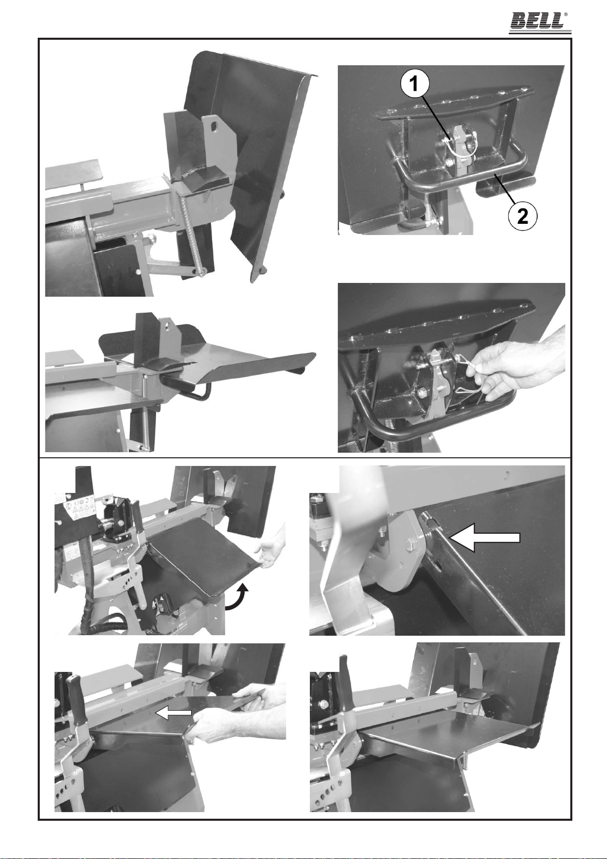
4.2.A - Abbassare il piano di raccolta legno
Per abbassare il piano di raccolta legno, togliere il perno di fi ssaggio del piano (1 in fi g.6b, pag.3), quindi accompagnare il piano fi no a che si trova
in posizione orizzontale. Infi lare e bloccare il perno nell'apposito foro del piano (fi g.6c), per evitare di perderlo.
ATTENZIONE
NON SI DEVE LA VORARE CON IL PIANO DI RACCOL T A DEL LEGNO IN POSIZIONE DI TRASPORTO (VERTICALE) IN QUANTO
SI CAUSEREBBERO SERI DANNI ALLA MACCHINA.
4.2.B - Sollevare il piano di appoggio legno
Per sollevare il piano di appoggio legno (11 in fi g.1, pag.2), seguire le istruzioni in fi g.7, pag.3
4.2.C - Regolazione dell'altezza della lama
Per regolare l'altezza della lama, azionare l'apposita leva di comando (2 in fi g.1, pag.2), muovendola verso sinistra per far alzare la lama (fi g.8d,
pag.4) e verso destra per abbassarla (fi g.8a). La leva può essere posizionata in 5 diversi fori che corrispondono a 5 altezze diverse della lama,
ottenendo così una lama a 4 vie (fi g.8e) che permette di rompere un tronco in 4 ceppi con una sola mandata. Scegliere l’altezza adeguata al tronco
che si sta spaccando, quindi spostare la leva e bloccarla nel relativo foro.
4.3 - Illuminazione
Tutte le zone della macchina devono essere illuminate in modo da garantire la loro perfetta visibilità durante il lavoro, le operazioni di manutenzione e
le regolazioni. Anche in caso di lavoro in esterni, è indispensabile che vi sia suffi ciente luce per poter eseguire il lavoro in sicurezza. È vietato lavorare
durante orari in cui la scarsità di luce può causare una cattiva visibilità della macchina e dei suoi componenti (alba, crepuscolo, notte).
5 - USO
ATTENZIONE
Non usare la macchina all’esterno quando piove o nevica.
In caso di non utilizzo, immagazzinare la macchina al riparo dagli agenti atmosferici.
5.1.A - Accensione e spegnimento dello spaccalegna elettrico (STS T10 E - STS T10 T)
• Verifi cate che l'interruttore/salvavita dell'impianto generale e l'interruttore della macchina siano spenti.
• Collegate lo spaccalegna elettrico all'impianto di alimentazione inserendo l'apposita presa nella spina situata sul motore elettrico.
• Prestate attenzione a non far passare il cavo di alimentazione nelle vicinanze della lama o comunque in un posto in cui potrebbe subire danni o troncarsi.
• Armate l'interruttore generale quindi accendete lo spaccalegna premendo il tasto verde dell'interruttore.
• Usate lo spaccalegna come spiegato nel paragrafo 5.2
• Se vi assentate spegnete lo spaccalegna, premendo il tasto rosso dell'interruttore (spento).
• Terminato il lavoro, togliete alimentazione alla macchina mettendo in posizione "0" (spento) l'interruttore/differenziale dell'impianto generale quindi
estraete la spina dalla presa sulla macchina. Nel compiere tale operazione, non tirate mai il cavo ma prendete il corpo della presa e toglietela.
5.1.B - Accensione e spegnimento degli spaccalegna azionati da trattore (STS T10 GC)
• Agganciate lo spaccalegna alla relativa fonte di moto (vedi cap.4 "MESSA IN FUNZIONE") quindi assicuratevi che lo spaccalegna sia ben posizionato a terra.
• Avviate il trattore facendo attenzione a non muoverlo dalla posizione in cui si trova. Mettete in funzione lo spaccalegna azionando il sistema di
alimentazione (presa di forza, cardano, ecc.). La lama si porterà in alto.
• Usate lo spaccalegna come spiegato nel paragrafo 5.2
• Se vi assentate spegnete lo spaccalegna, disattivando il sistema di trasmissione del trattore.
• Una volta terminato il lavoro, disattivate il sistema di trasmissione e staccate l'albero cardanico dal trattore.
• Prima di spostare il trattore, sollevate lo spaccalegna ad un'altezza suffi ciente affi nchè non batta a terra.
ATTENZIONE
Non mettete in movimento il trattore con la fonte di alimentazione dello spaccalegna azionata o con lo spaccalegna ancora a terra.
D22002300 v.0 - UPD 180612
13
Page 14

s.r.l.
ITALIANO
5.2 - Uso dello spaccalegna
Posizionate un tronco le cui dimensioni non superino quelle indicate in fi g.3 a pag.2 sulle guide appoggiatronco (4 in fi g.1, pag.2).
Operando solamente dalla posizione consentita (13 in fi g.1, pag.2), azionate CON ENTRAMBE LE MANI le leve di comando tirandole verso voi
stessi: lo spingitronco inizierà a premere il tronco contro la lama che lo spaccherà in pochi secondi.
Il comando di azionamento permette di gestire la velocità e la potenza di lavoro per adattarsi nel migliore modo possibile
al tipo di legno che si vuole rompere: se il legno è morbido, tirate una leva fi no a battuta e l’altra fi no a circa metà cor-
sa; lo spingitronco si azionerà più velocemente pur lavorando con una forza di spinta ridotta. Se il legno da spaccare è
particolarmente duro o stagionato, tirate entrambe le leve fi no a battuta: lo spingitronco risulterà più lento ma si avrà il
massimo della potenza, così da avere maggiori possibilità di rottura del legno duro.
La velocità può essere variata anche durante la rottura del legno, semplicemente tirando più o meno la leva verso voi stessi.
ATTENZIONE:
trova. Spingendo entrambe le leve nella direzione opposta all'operatore, lo spingitronco inizierà la corsa di ritorno fi no a raggiungere la posizione
iniziale, alla massima distanza dalla lama. Le due leve rimarranno bloccate nella posizione di ritorno, consentendo all'operatore di avere le mani libere
e torneranno in posizione centrale automaticamente quando lo spingitronco sarà a fi ne corsa.
Lasciando andare una oppure entrambe le leve del comando, automaticamente lo spingitronco si fermerà nella posizione in cui si
Ripetete l'operazione con i pezzi ottenuti in modo da spaccare il ceppo in più parti.
ATTENZIONE: Lo spaccalegna è in grado di esercitare una pressione sul tronco pari a circa 10 tonnellate, più che suffi ciente a rompere legni anche
molto stagionati. Nel caso in cui la macchina non riuscisse a rompere tronchi troppo duri, non forzate il cilindro per più di 30 secondi in quanto l'olio
idraulico potrebbe surriscaldarsi in maniera eccessiva e causare danni al circuito idraulico. In questo caso è conveniente sbloccare il tronco e tentare
di romperlo in altra posizione (ruotandolo di 90°) oppure scartarlo.
ATTENZIONE
É IMPORT ANTE CHE L'OPERAT ORE LA VORI SOLAMENTE NELLA ZONA DI LA VORO CONSENTIT A INDICA T A IN FIG.1 A P AG.2
(POS.13) E CHE NESSUNO SOSTI IN UN RAGGIO DI 5 METRI DALLA MACCHINA DURANTE LE OPERAZIONI DI LAVORO.
ATTENZIONE
IL COSTRUTTORE DECLINA OGNI RESPONSABILITÀ PER DANNI A PERSONE, ANIMALI O COSE, CAUSATI DA UN USO
IMPROPRIO DELLA MACCHINA
5.3 - Movimentazione dello spaccalegna
Lo spaccalegna deve essere movimentato sollevandolo per l'apposita maniglia posta sul retro del piano raccolta legno (2 in fi g.6b, pag.3).
Movimentare lo spaccalegna esclusivamente con il piano appoggio legna (11 in fi g.1, pag.2) abbassato e il piano raccolta legna (12 in fi g.1), sollevato
(fi g.6a, pag.3) e bloccato con l'apposito perno di fi ssaggio (1 in fi g.6b).
14
D22002300 v.0 - UPD 180612
Page 15

ITALIANO
s.r.l.
6 - MANUTENZIONE ORDINARIA
In questo capitolo vengono descritte le operazioni di manutenzione ordinaria, pertanto quelle effetuate dall'operatore, sullo spaccalegna al fi ne di
mantenerlo sempre in perfetta effi cienza e quindi affi dabile per un uso continuativo e duraturo.
Ogni operazione di manutenzione ordinaria deve essere compiuta a macchina spenta e, nel caso di spaccalegna ad alimentazione elettrica, con il
cavo di alimentazione disconnesso.
Ogni altra operazione di manutenzione non specifi catamente contemplata in questo manuale deve essere effetuata da personale autorizzato
in quanto si possono creare situazioni di pericolo sulle quali l'operatore non è preparato.
Ogni operazione di manutenzione straordinaria o sostituzione di parti di ricambio non effetuate da personale autorizzato, fanno immediatamente decadere la garanzia e sollevano il costruttore da qualsiasi responsabilità per danni a persone, animali o cose.
6.1 - Sostituzione dell'olio idraulico
Ogni 400 ore di lavoro è necessario sostituire l'olio esausto con altro olio nuovo del tipo riportato a pag.10.
Per sostituire l'olio procedete come segue.
Assicuratevi che lo spingitronco della macchina sia completamente rientrato.
Mettete sotto al tappo di scarico olio (fi g.9a, pag.4), situato nel retro della macchina, una vasca di raccolta che possa contenere circa 10 litri di olio.
Svitate il tappo di scarico con una chiave adeguata e lasciate scendere nella vaschetta tutto l'olio contenuto nel serbatoio.
Quando il serbatoio è completamente svuotato, pulite l'imbocco e il tappo di scarico con benzina, quindi riavvitatelo.
Sfi late il tappo dell'olio (fi g.9b, pag.4) e riempite il serbatoio con olio adatto (olii da usare indicati a pag.10), circa 10 litri.
Accendete lo spaccalegna e mettetelo in funzione facendogli compiere 1/3 della corsa completa.
Fate rientrare completamente lo spingitronco quindi aggiungete l'olio rimanente e fate compiere alla macchina due cicli completi per permettere
la fuoriuscita dell'aria dal circuito idraulico.
Pulite l'imbocco del tappo dell'olio, reinserite il tappo e verifi cate con l'astina di livello (fi g.9b, pag.4) che vi sia la giusta quantità di olio.
ATTENZIONE:
NON GETTATE L'OLIO ESAUSTO FRA I RIFIUTI GENERICI!
L'OLIO ESAUSTO DEVE ESSERE SMALTITO SECONDO LE PRESCRIZIONI DI LEGGE IN VIGORE NEL PAESE DI UTILIZZO
DELLA MACHINA.
6.2 - Affi latura della lama
Dopo numerose ore di lavoro e comunque in caso di bisogno, affi late la lama dello spaccalegna usando una lima a denti fi ni e facendo attenzione ad
asportare anche eventuali bave o schiacciature del metallo.
7 - INCONVENIENTI E RIMEDI
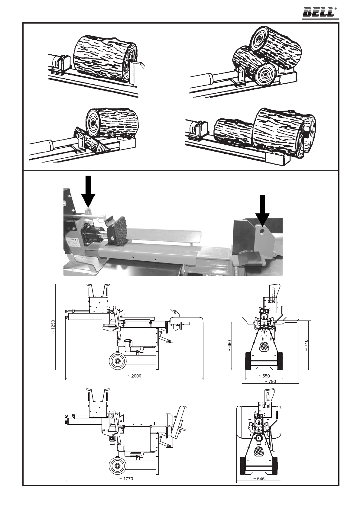
7.1 - Disincastro del legno bloccato (fi g.10, pag.5)
Nel caso si incastrasse il tronco da rompere nella lama procedete al disincastro come spiegato di seguito.
Fig. 10A: Ritirate completamente lo spingitronco azionando entrambe le leve del comando ZHB verso di voi.
Fig. 10B: Prendete un cuneo di legno precedentemente spaccato ed incastratelo di traverso, sotto al tronco bloccato quindi azionate lo spingitronco
in modo da spingere il cuneo completamente sotto al tronco incastrato. Questa operazione dovrebbe essere suffi ciente per sbloccare il tronco.
Fig. 10C: Nel caso il tronco fosse ancora incastrato, togliete il cuneo e metteteci sotto un tronco intero poi azionate lo spingitronco fi no al completo
disincastro del tronco bloccato.
Fig. 10D: Se vi capitasse che il tronco non si spacca quando lo spingitronco è arrivato a fi ne corsa, ritraetelo e ponete davanti al tronco incastrato un
altro tronco poi azionate lo spaccalegna: il secondo tronco spingerà quello incastrato rompendolo.
ATTENZIONE
DURANTE LE OPERAZIONI DI DISINCASTRO DEL LEGNO NON FATEVI MAI AIUTARE DA TERZI.
NEL CASO IN CUI IL TRONCO DOVESSE ESSERE RIMOSSO MANUALMENTE, ASSICURATEVI CHE LO SPACCALEGNA
ED IL TRATTORE SIANO SPENTI.
PER TUTTE LE OPERAZIONI DESCRITTE IN PRECEDENZA VALGONO TUTTE LE REGOLE DI SICUREZZA DESCRITTE
NEL CAP.3 "SICUREZZA" A PAG.10.
IL COSTRUTTORE NON RISPONDE IN ALCUN MODO PER DANNI ALLE PERSONE, AGLI ANIMALI E AGLI OGGETTI CAUSA TI
DA UN USO IMPROPRIO DELLA MACCHINA O DALL'INOSSERVANZA DELLE NORME DESCRITTE.
D22002300 v.0 - UPD 180612
15
Page 16

s.r.l.
ITALIANO
7.2 - Ricerca e soluzione dei problemi
La seguente tabella riporta i possibili problemi che possono verifi carsi durante l'uso dello spaccalegna ed i relativi rimedi consigliati.
Ogni intervento da parte di personale non specializzato fa decadere immediatamente la garanzia della macchina e solleva il costruttore da qualsiasi
responsabilità per danni causati alle persone, agli animali e alle cose.
Problema
Il tronco non si spacca
Lo stelo avanza a scatti o con forti vibrazioni. Esce olio schiumoso dal tappo di
riempimento.
Perdita di olio dai raccordi, dalla pompa
o dal cilindro
Il tronco è di dimensioni più grandi di quelle
consentite
Errato posizionamento del tronco
La lama non taglia
Perdita di olio
Pressione idraulica troppo bassa
Presenza di aria nel circuito
Raccordi lenti
Guarnizioni usurate
Probabile causa
Rimedio
Cercare di tagliarne una piccola parte o ridurre con
altri mezzi la dimensione del tronco.
Sistemare correttamente il tronco
Affi lare la lama; controllare bave o tacche, limare
se necessario
Individuare la perdita usando un pezzo di carta o
di legno. Contattare il rivenditore.
Contattare il rivenditore
Controllare il livello dell'olio e, se necessario,
aggiungerne.
Controllare che la pompa non aspiri aria.
Verifi care che, nel tratto di circuitoche va dal
serbatoio alla pompa, i raccordi non siano lenti o
il tubo danneggiato.
Se il problema persiste contattate il rivenditore.
Stringere i raccordi
Contattare il rivenditore
7.3 - Riarmo della protezione termica del motore elettrico
Durante il lavoro con macchine alimentate elettricamente, nel caso di un sovraccarico, uno sbalzo molto forte di tensione oppure un guasto accidentale all'impianto elettrico, interverrà un dispositivo di protezione applicato al motore e integrato nell'interruttore generale. in caso di intervento della
protezione, prima di chiamare il centro di assistenza autorizzato, attendete alcuni minuti quindi provate a riarmare l'interruttore generale. Se non si
ripresenta il problema, potete usare la macchina tranquillamente. Se invece la protezione dovesse saltare ancora, non insistete nel tentativo di farla
rimanere agganciata e contattate il centro di assistenza tecnica autorizzata.
DEMOLIZIONE E SMALTIMENTO DELLA MACCHINA
La demolizione della macchina deve essere eseguita rispettando tutte le norme di sicurezza atte ad evitare danni alle persone, all'ambiente e agli animali.
Tutte le parti della macchina devono essere rottamate e smaltite secondo le leggi vigenti nel luogo in cui viene effettuata la demolizione.
Particolare attenzione è da porre nello smaltimento dell'olio idraulico e delle apparecchiature elettriche. Entrambe non devono essere dispersi nell'ambiente in quanto altamente inquinanti, ma devono essere smaltiti secondo le prescrizioni di legge.
Le macchine dotate di apparecchiature elettriche non devono essere smaltite come rifi uti misti, ma attraverso una raccolta differenziata separata,
presso i punti autorizzati.
Il produttore è impegnato nel riciclaggio dei rifi uti (RAEE) attraverso l'adesione agli appositi consorzi di smaltimento.
Uno smaltimento non conforme alle prescrizioni di cui sopra è sanzionabile a norma di legge.
16
D22002300 v.0 - UPD 180612
Page 17

ITALIANO
s.r.l.
GARANZIA
La ditta BELL S.r.l., denominata qui di seguito come BELL, garantisce al compratore di ogni nuovo prodotto originale BELL, acquistato da un rivenditore autorizzato BELL, che tale prodotto è esente da difetti di materiale e manodopera per un periodo di 360 giorni (12 mesi) dalla data dell’acquisto
originale o dalla data del primo noleggio.
Le parti di ricambio installate sul prodotto coperto da questa garanzia, sono garantite per 90 giorni (3 mesi) dalla data di sostituzione o riparazione.
Tali parti devono essere fornite gratuitamente all’utilizzatore dal rivenditore o distributore BELL durante le ore lavorative regolari.
BELL si riserva il diritto di ispezionare ogni prodotto o parte sostituita come difettosa. Le parti sostituite devono quindi essere conservate e tenute a
disposizione per 12 mesi.
È espressamente inteso che la BELL non ha obblighi di fornire manodopera o di accettare spese di trasporto.
BELL non si assumerà alcuna responsabilità per danni, difetti o costi derivanti da riparazioni e/o modifi che di un prodotto BELL, effettuati da qualsiasi
persona che non sia un tecnico autorizzato BELL.
Questa garanzia non sarà applicata ai componenti commerciali coperti da loro propria garanzia, quali motori a scoppio, diesel, ecc...
Non sono coperte da garanzia macchine o loro parti deteriorate da:
1) Uso scorretto o improprio, negligenza, abuso o incidente.
2) Mancanza di ragionevole o necessaria manutenzione come prescritto in questo manuale (Sostituzione di olio idraulico, olio motore, olio per moltiplicatore consumati o esausti, lama non affi lata, ecc...)
3) L’uso di parti o accessori non costruiti, forniti o approvati da BELL.
La BELL non presta ulteriori espresse o sottintese garanzie, eccetto quelle qui contenute.
Ogni prolungamento del periodo di garanzia o estensione della stessa non verranno riconosciuti come validi e quindi applicati dalla BELL.
(Nessun rappresentante o rivenditore è autorizzato ad assumere altre responsabilità riguardo ai prodotti BELL.
La durata delle garanzie implicite riconosciute dalla legge, incluse le garanzie commerciali e convenienze per particolari scopi sono limitate
nella durata alla validità e durata della espressa garanzia qui sotto concesse.)
In nessun caso la BELL riconoscerà perdite di profi tto, dirette o indirette, speciali o conseguenti a eventuali danni.
In caso di richiesta di ricambi o interventi di riparazione, sono indispensabili le seguenti informazioni:
MODELLO .........................................................................................................
NUMERO DI SERIE ..........................................................................................
DATA DI ACQUISTO .........................................................................................
D22002300 v.0 - UPD 180612
17
Page 18

s.r.l.
ENGLISH
TRANSLATION OF ORIGINAL INSTRUCTIONS
INTRODUCTION
BELL® log splitters have been designed and manufactured in compliance with the most recent European safety regulations with particular reference
to the EN 609-1 and CEI EN 60204-1 standards.
The two-hands control systems, in fact, have been designed and engineered so that the operator is forced to work in the safety area, employing both
the hands, without any possibility of inserting hands or arms in dangerous areas.
This log splitter machine is produced in conformity with the specifi cations contained in the RoHs directive 2002/95/CE
Before transporting, installing or operating the machine, read all parts of this manual, paying particular attention to the specifi c safety
regulations.
Operators who are unable to understand any of the languages in which this manual is written are responsible for asking the retailer to provide a manual
in their own language.
The operator must also train any other person authorised to use the machine.
Failure to comply in any way with these instructions, improper use of the machine, extraordinary maintenance operations not carried out by
skilled, authorised personnel, removal of data plates or markings of any type, removal or tampering with the guards and safety mechanisms
of the machine or any other action not expressly authorised that may impair the active and passive safety systems of the machine shall
relieve the manufacturer of all and any liability and may result in serious injury and damage.
If the machine is tampered with in any way by unauthorised personnel, the guarantee is automatically null and void. This manual is an integral part of
the machine and must accompany it even in the case of transfer of ownership.
WARNING: The ignition system of your machine produces an electromagnetic fi eld of very low intensity. This fi eld could interfere with
certain pacemakers. To reduce the risk of serious or fatal injury, persons with pacemakers should consult their doctor or the manufacturer
of the pacemaker before using this machine.
1 - DESCRIPTION OF THE MACHINE
This series consists of portable, horizontal log splitters, which are provided with either their own electric motorization or an external connection for
operation by means of a tractor. The various parts of the machine are shown in fi g.1, page 2.
1 - ZHB control levers
2 - Wedge handling lever
3- Log pusher
4 - Log retention brackets
5 - Wedge
6 - Cylinder
7 - Oil tank
8 - Oil plug
9 - Electric motor
10 - Wheels for minor movements
11 - Log support plate
12 - Log collection plate
13 - PERMITTED AND MANDATORY WORK AREA
18
D22002300 v.0 - UPD 180612
Page 19

ENGLISH
1.1 - Symbols used
Standard graphic symbols are used on all machines in order to ensure complete safety of all parts of the log splitter.
As these symbols are very important, read the information below attentively.
s.r.l.
It's necessary to read carefully the entire use and maintenance manual of the machine, before using it
it is obligatory to wear safety footwear at all times to
provide protection against the risk of logs accidentally
falling on feet.
it is obligatory at all times to wear gloves which protect
the hands against chips and splinters which may be
produced during work.
it is obligatory at all times to wear goggles which protects
the eyes against chips and splinters which may be produced during work.
The log splitter must be used by one person alone.
Danger of cutting or crushing of the hand: never touch
hazardous areas while the wedge is moving.
Direction of rotation of the motor. If the motor runs
in the wrong direction, follow the instructions given
in chapter 4.1.A, page 22.
Warning: voltage as indicated on the rating plate
Machines fi tted with electrical parts must not be dispo-
sed of as general waste and must be separated for
disposal as separately collected fractions, deposited
at authorised collection points.
B93250240
Hitch point
Make certain that the gearbox shaft rotates
in the direction ahown in fi gure and does
not exceed 540 rpm.
it is forbidden to stand in the range of action of the
machine. apart from the operator, no other person or
animal may be present within a radius of 5 metres from
the machine.
Dumping of used oil in the environment is forbidden. The
oil must be disposed of according to current legislation in
the country where this operation is carried out.
Danger of cutting or crushing of the hand: never touch
hazardous areas while the wedge is moving.
Warning: always pay attention to the movement of the
log pusher.
Warning: never remove a log trapped in the wedge
with your hands.
Regulation of the wedge height:
By activating the lever to the left, ascends the wedge.
By activating the lever to the right, descends the wedge,
until it shows two ways only
Two hands control: by activating both the
levers, the log is pushed against the wedge,
by the logpusher, until it is splitted.
When the cylinder is moving, do not try to
move the wedge.
Warning: Before carrying out any maintenance operation described in this manual, disconnect the plug
of the machine.
D22002300 v.0 - UPD 180612
Regulating speed with the control lever: in the fi rst
position, about halfway down, the log splitter is
faster but less powerful; with the lever pressed all
the way, the machine slows down but splits the log
at full power.
19
Page 20

s.r.l.
2 - TECHNICAL DATA
STS T10 STS T10 STS T10
E T GC
Lenght (mm) ~ 790 ~ 790 ~ 980
Widht (mm ~ 2000 ~ 2000 ~ 2000
Height (mm) ~ 1250 ~ 1250 ~ 1250
Weight (kg) ~ 157 ~ 157 ~ 150
Max. force (tons.) ~ 10 ~ 10 ~ 10
Log capacity (mm) ~ 600 ~ 600 ~ 600
Hydraulic oil total capacity (lt.) ~ 11 ~ 11 ~ 11
Supply 230V 50Hz 1-phase 400V 50Hz 3-phase Attach to cardanshaft
Absorption 13A 7,4A ——
Power 3Hp - 2,2kW 4Hp - 3kW ——
ENGLISH
Noise ≤ 85 dB(A) measured at the height of the operator’s ear in the working position with the log splitter in operation
• The ears must be suitably protected (ear defenders).
• If the machinery is connected to a tractor, the noise it produces is negligible compared to the noise produced by the tractor.
2.1 - Right way to lift the machine
The machine must be lifted by means of lifting hooks with capacity bigger than 200 Kg. that must be fi xed in the hitch points (fi g.11, page 5)
2.2 - Size of the logs to be split
Figure 3 on page 2 shows the maximum log sizes that can be split.
The diameter of the log is indicative: a small log can be diffi cult to split if it has knots or is of a particularly twisted fi bre.
2.3 - Recommended oils
We recommend use of the following oils for the hydraulic cylinder:
SHELL TELLUS S2 V 22
ARAL VITAM GF22
BP ENERGOL HCP22
TEXACO RANDO HDZ 22/32
MOBIL DTE11 or equivalent.
DO NOT USE OTHER GRADE OILS.
3 - SAFETY
The information given in the chapter is extremely important for safety purposes. It describes possible hazards tied to use of the machine
and instructions for correct use of this to avoid injury or damage.
WARNING: This log splitter has been designed and manufactured to split logs of the sizes recommended on page 2, fi g.3 only.
Use of the machine for any other purpose shall be considered improper and the manufacturer shall not be liable for any injuries or damage
to be ascribed to improper use of the machine.
The operator must work in the position shown in fi g.1 on page 2 (pos.13) only and operate the machine drive control with both hands without using
other improvised systems and without tampering with the controls.
When the machine is working, persons and animals must be kept at a distance of at least 5 meters from the machine.
NEVER ATTEMPT TO TAMPER WITH THE PROTECTIONS OF THE LOG SPLITTER OR TO OPERATE THE MACHINE WITHOUT THESE. FAILURE TO COMPLY WITH THE INSTRUCTIONS GIVEN IN THIS CHAPTER MAY RESULT IN SERIOUS INJURY OR DAMAGE TO PERSONS,
THINGS AND TO THE MACHINE.
Do not use the log splitter to break stone materials (stones, concrete, etc.). Or to crush pieces or metal containers.
20
D22002300 v.0 - UPD 180612
Page 21

ENGLISH
s.r.l.
3.1 - General safety regulations
• The machine must always be used by one operator only.
• Do not use the machine outdoor when it is raining or snowing.
• Nobody must be allowed to use the log splitter unless they have read the instruction manual and have been instructed in the regulations to follow
for correct and safe use.
• The machine must be used by adults only. Use of the log splitter by apprentices of not less than 16 years of age must be supervised by an adult
authorised to use the machine.
• Never wear loose, unbuttoned clothing which may become trapped in moving parts.
• Do not move the log splitter while the motor is running.
• Use a piece of cardboard or wood rather than the hands in order to search for eventual oil leakages.
Oil jets under pressure can penetrate under skin. In this case, see a doctor at once.
• Do not work on sloping or slippery ground. position the machine in a fl at area free from objects which may impede the freedom of movement of
the operator.
• Check that the logs to be split are free from nails or wire, which may fl y up or damage the machine. The ends of the logs must be cut square.
Branches must be cut off fl ush with the trunk.
• Never try to split logs larger than those indicated in fi g. 3. This could be dangerous and may damage the machine.
• Break wood in the direction of the grain. Do not place wood across the log splitter and leave it in that position for splitting; it may be dangerous and
may seriously damage the machine.
• Never attempt to cut two logs at once; one may fl y up and hit you.
• If the log moves away from the blade, retract the ram or the blade and turn the log through 90°.
• Do not attempt to load the log in the log splitter while the ram is in motion. you could get trapped and injured.
• Keep your hands well away from any splits and cracks which open in the log; these may close suddenly and crush or amputate your fi ngers.
• Do not force the log splitter for more than 30 seconds by keeping the cylinder under pressure at the end of its stroke, or by persisting when a log
does not split or gets stuck on the blade. Oil under pressure overheats very rapidly, damaging the pump.
• Never leave the machine unattended while it is running. If you leave the machine, even for a short time, remove the power supply or any possible
cause of accidental start-up.
• The log splitter must never be used by an operator who is under the infl uence of alcohol, drugs, medicines, or who is tired. A clear mind is essential
for safety.
• Never try to release a jammed log while the machine is running. The machine must be switched off during this operation.
• Never request the assistance of another person to help you remove a jammed log.
• Do not use alcohol, petrol, or solvents to clean the machine. This could cause the safety information applied to the machine itself to become illegible.
3.1.A - For machines with electric motor (STS T10 E - STS T10 T)
• Do not use machines with electric motor if natural gas, petrol fumes or other infl ammable vapours are present.
• Check that the electric circuit to which the machine will be connected is suitable. Power, voltage and frequency of the motor
must be checked (verify the nameplate on the motor and the data in this manual). The machine must be connected to a circuit with a regulation
differential switch upstream and, in compliance with the norms (30 mA rated fault current), with a ground connection.
• Use cables with a section of 2.5 mm2. Avoid use of free and inadequately insulated connections. Connections must be made with protected material
suitable for outdoor use. Do not use cable extensions longer than 5 mt.: too long cables or cables with inadequate section
may cause voltage drops and don’t allow the motor to develop all the power.
before using it.
• Make sure that the machine and the cable never come in contact with water.
• To prevent accidental start-up, ensure that the switch is “off” before plugging in the power cable.
• Treat the power cable with care. do not attempt to move the machine by pulling the cable. do not yank the cable to unplug it; keep the cable away
from excessive heat, oil and sharp objects.
• Never leave the machine unattended with the power supply “on”. After use, always switch the machine off and disconnect it from the power supply,
especially when any maintenance work is required.
Always check the cable extension for any damage
3.1.B - For machines driven by cardan shaft (STS T10 GC)
• Never connect the log splitter with the tractor moving.
• Make sure that the machine is properly fi xed to the 3 points of the tractor.
• Make sure that the cardan shaft is fully inserted in the power take-off and has clicked in place.
• Never touch the cardan shaft with the engine running.
D22002300 v.0 - UPD 180612
21
Page 22

s.r.l.
ENGLISH
4 - OPERATING THE MACHINE
The log splitter, in compliance with standard EN 609-1, is activated with a two hand control: the machine will function only when both the levers
are activated together (1 in fi g.1, page 2).
Never use the log splitter if it is not in perfect order or if it needs servicing. Before starting work, check correct functioning of all the safety devices
(two hands control and switch-off button).
Before starting work, check the integrity of the fl exible pipes and the lack of leaks in the connections, check the level of the hydraulic oil in the tank
and top up if necessary with one of the oils indicated on page 20.
The oil level must be between the two notches on the oil dipstick (fi g.9b, page 4)
Before starting work, switch on the log splitter and let the oil warm up for a few minutes.
4.1.A - For machines with 3-phase electric motor (STS T10 T)
If the motor does not run in the correct direction, invert two of the phases in the socket. Remove the plug from the log splitter. Insert a slotted screwdriver
with a suitably sized wedge in the slot located in the connection inlet close to the electric motor as shown in fi gure 2, page 2.
Exerting a slight pressure, turn the white wheel by 180°. This operation physically inverts the poles on the three-phase motor.
Check that the motor runs in the correct direction as indicated by the arrow.
Never open the box containing the switch, or open the terminal block on the motor. if it is necessary to do so,
have these operations carried out by your electrician.
If the fuses blow or the protection valve trips, this means that you are overloading the motor or the electrical installation is not correctly rated. Consult
your electrician.
4.1.B - For machines driven by cardan shaft (STS T10 GC)
WARNING
USE CE-MARKED CARDAN SHAFT ONLY. CAREFULLY FOLLOW THE MANUFACTURER OPERATING INSTRUCTIONS
Make sure the tractor is off, that the parking brake is on and if necessary that the wheels are chocked.
Connect the log splitter to the three points of the tractor.
Connect the cardan shaft to the gearbox (fi g.5b, page 2) to the power take-off of the tractor. The cardan shaft must be of suitable length and com-
plete with protective cover. Check that it clicks into place.
After connecting the log splitter, start the tractor and check that the cardan shaft turns in the direction indicated on the data plate on the gearbox
(see par. 1.1 “SYMBOLS USED” on page 19).
Position the accelerator at a suitable rpm for your tractor so that the engine provides suffi cient power for correct functioning of the log splitter and
check that the power take-off does not exceed 540 rpm as shown on the data plate (see par. 1.1 “SYMBOLS USED” on page 19)
WARNING
FOLLOW THE FEW VERY IMPORTANT RULES INDICATED ABOVE TO AVOID PROBLEMS THAT COULD CAUSE INJURY OR
DAMAGE.
WARNING
NEVER TOUCH THE CARDAN SHAFT OR ANY OTHER ROTATING PARTS. THIS IS EXTREMELY DANGEROUS AND MAY
CAUSE INJURY OR DAMAGE.
When the machine is not in use or when it’s working, the cardan shaft support (A in fi g.4 and 5, page 2) must be positioned as shown in fi g.4.
In order to hold the cardan shaft while it’s connecting or disconnecting, position it (B in fi g.5b) on the appropriate support (A), as shown in fi g.5.
22
D22002300 v.0 - UPD 180612
Page 23

ENGLISH
s.r.l.
4.2.A - How to lower the log collection plate
In order to lower the log collection plate, extract the plate fi xing pin (1 in fi g.6b, page 3) and guide the plate until it's in horizontal position. Put the
pin into its hole on the plate (fi g.6c), in order to avoid to lose it.
WARNING
NEVER SET THE MACHINE IN ACTION WITH THE LOG COLLECTION PLA TE IN TRANSPORT POSITION (VERTICAL / CLOSE)
WHILE THAT COULD CAUSE SERIOUS DEMAGES TO THE MACHINE
4.2.B - How to lift the log support plate
In order to lift the log support plate (11 in fi g.1, page 2), follow the instructions in fi g.7, page 3.
4.2.C - Regulation of the wedge height
In order to regulate the height of the wedge, operate the appropriate control lever (2 in fi g.1, page 2) by activating it to the left to lift the wedge
(fi g.7d, page 4) and to the right in order to lower the wedge (fi g.7a). The lever can be positioned in 5 different holes that correspond to 5 different
heights of the wedge, in order to obtain a 4-ways wedge (fi g.7e) that allows to split a trunk into four logs with a single stroke. Choose the suitable
height for the trunk you are splitting, then move the lever and lock it into the appropriate hole
4.3 - Lighting
Lighting must be provided in the entire work area of the log splitter to ensure perfect visibility when operating the machine and during maintenance
and adjustments. Even when working outdoors, there must be suffi cient light to work safely. Working at times when insuffi cient light may result in poor
visibility of the machine and its components (dawn, dusk, night) is forbidden.
5 - USE
WARNING:
DO NOT USE THE MACHINE OUTDOOR WHEN IT IS RAINING OR SNOWING.
WHEN NOT IN USE, STORE THE MACHINE WHERE IT IS PROTECTED FROM ATMOSPHERIC AGENTS.
5.1.A - Switching on/off of the machine with electric motor (STS T10 E - STS T10 T)
Make sure that the switch/cutout of the general power system and the switch of the machine are OFF.
Connect the electric log splitter to the power system inserting the plug in the socket on the electric motor.
Never pass the power cable over the telescopic mast, close to the wedge or anywhere where it may be damaged or cut.
Set the main on/off switch and then press the switch in the green area to start the log splitter.
The telescopic mast will move automatically to the fully open position.
Use the log splitter as explained in paragraph 5.2.
Never leave the log splitter unattended without fi rst of all pressing the switch in the red area (off).
On completing the work, switch off the log splitter by turning the switch/differential of the general power system to the “0” position (off) and then
remove the plug from the socket on the machine. Never yank the plug using the cable. Grasp the body of the plug and pull it fi rmly.
5.1.B - Switching on/off of the machine driven by cardan shaft (STS T10 GC)
Connect the log splitter to the power source (see chapter 4 “OPERATING THE MACHINE”) and then check that the machine is fi rmly positioned
on the ground.
Start the tractor making sure it does not move. Start the log splitter by activating the power system (cardan shaft). The wedge will lift.
Use the log splitter as explained in paragraph 5.2.
If you leave the log splitter unattended, switch off the transmission system of the tractor.
After using the log splitter, switch off the transmission system, switch off the tractor. Before moving the tractor, lift the log splitter to a suffi cient
height so that it does not hit the ground.
WARNING
NEVER MOVE THE TRACTOR WITH THE POWER SOURCE OF THE LOG SPLITTER ACTIV A TED OR WITH THE LOG SPLITTER
STILL ON THE GROUND.
D22002300 v.0 - UPD 180612
23
Page 24

s.r.l.
ENGLISH
5.2 - How to use the log-splitter
Place a log on the log retention brackets (4 in fi g.1, page 2), making sure it is not larger than the dimensions indicated on page 2, fi g.3.
Working in the mandatory position only (13 in fi g.1 page 2), operate the control levers WITH BOTH HANDS, pulling them towards you: the log
pusher will start to push the log against the wedge, and it will split after a few seconds.
The control system enable you to manage the work speed and power to adapt to the type of wood to be split in the best
way possible. If the wood is soft, pull one of the two control lever completely and pull the other one about halfway: the
log pusher is activated faster but works with reduced thrust. If the wood is particularly hard or seasoned, pull both the
control lever completely: the log pusher is slower but has the maximum power, with greater possibility to break hard
wood. The speed can be varied during the operation simply by pulling more or less the lever towards yourself
WARNING: Releasing one or both the control levers, the log pusher will stop where it is. Pushing both levers ahead, the log pusher will come back to
the start position, fully open position (max distance from the wedge). The two levers will remain blocked in the return position, enabling the operator to
have both hands free and the levers will automatically return to the central position when the log pusher reaches its end stop.
Repeat the operation with the pieces obtained so as to split the log into several parts.
WARNING: The log splitter exercises a pressure of about 10 tonnes on the log, more than enough to split even very seasoned wood. Should a log
prove to be too hard for the machine to split it, do not force the cylinder for more than 30 seconds as the hydraulic oil could overheat and damage the
hydraulic circuit. In this case, remove the log and try to split it in another position (turning it 90°) otherwise reject it.
WARNING
IT IS IMPORTANT THAT THE OPERATOR WORKS ONLY IN THE PERMITTED WORK AREA AS SHOWN IN FIG.1 ON PAGE 2
(POS.13) AND THAT NO OTHER PERSON REMAINS WITHIN A 5 METRE RADIUS OF THE MACHINE WHEN IT IS BEING USED.
WARNING
THE MANUFACTURER IS NOT LIABLE FOR INJUR Y TO PERSONS, ANIMALS OR OTHER THINGS CAUSED BY AN IMPROPER
USE OF THE MACHINE
5.3 - Moving the log splitter
The log splitter must be moved by lifting it with the handle on the back of the log collection plate (2 in fi g.6b, page 3).
Move the log splitter only with lowered log support plate (11 in fi g.1, page 2) and lifted log collection plate (12 in fi g.1). The log collection plate must be
blocked with the appropriate fi xing pin (1 in fi g.6b).
24
D22002300 v.0 - UPD 180612
Page 25

ENGLISH
s.r.l.
6 - ROUTINE MAINTENANCE
This chapter describes routine maintenance, i.e. operations carried out by the operator, on the log splitter to keep this in perfect working order and
therefore reliable for continuous, long-term use. All routine maintenance operations must be carried out with the machine off and in the case of log
splitters with electric motor with the power cable disconnected.
Any other maintenance operation not specifi cally envisaged in this manual must be carried out by authorised personnel only in that hazar-
dous situations may arise for which the operator is not prepared.
In the case in which extraordinary maintenance or part replacement operations are not carried out by authorised personnel, the guarantee
shall be immediately null and void and the manufacturer shall be relieved of any responsibility for injury to persons or animals or damage.
6.1 - How to change the hydraulic oil
The spent oil must be replaced with new oil of the type indicated on page 20 (Recommended oils) every 400 hours of operation.
To change the oil, proceed as follows.
Make sure that the log pusher is fully retracted.
Place a collection tray able to hold around 10 litres of oil under the oil drainage dowel (fi g.9a, page 4), on the rear of the machine.
Unscrew the dowel with a suitable allen wrench and let all the oil in the tank drain into the collection tray.
When the tank is completely empty, clean the drain outlet and cap with petrol, then screw the cap back into place.
Remove the oil cap (fi g.9b, page 4) and fi ll the tank with suitable oil (the oils to be used are indicated on page 20), about 10 litres.
Activate the log splitter and let the log pusher make some strokes in order to let any air bubble come out from the circuit.
Add the remaining oil and use the oil rod to check the right quantity of oil (fi g.9b): the oil level must be between the two notches on the oil dipstick
Clean the inlet of the oil plug and replace the plug.
WARNING:
NEVER MIX OIL WITH GENERAL WASTE!
USED OIL MUST BE DISPOSED OF ACCORDING TO CURRENT REGULA TIONS IN THE COUNTR Y WHERE THE MACHINE IS USED.
6.2 - Sharpening the wedge
After long periods of operation and when required, sharpen the wedge of the log splitter using a fi ne-toothed fi le and taking care to remove any burrs
or crushed parts of the metal.
7 - TROUBLESHOOTING
7.1 - How to free a jammed log (fi g.10, page 5)
Should the log you wanted to split become jammed onto the wedge, remove it as follows.
Fig. 10/A: Retract the log pusher completely operating both the control levers towards yourself.
Fig. 10/B: Take a previously split wooden wedge and insert it crosswise, underneath the jammed log. Now operate the log pusher so that the wooden
wedge is pressed fully underneath the jammed log. This should be enough to release the log.
Fig. 10/C: If the log is still jammed, remove the wooden wedge and put a whole log underneath. Now operate the log pusher until the jammed log is freed.
Fig. 10/D: If the log is not split when the log pusher has completed its run, retract it and place another log in front of the jammed log. Now operate the
log pusher: the second log will push against the jammed one and split it.
WARNING
NEVER ASK FOR THE ASSISTANCE OF ANOTHER PERSON WHEN FREEING A JAMMED LOG.
IF YOU HAVE TO REMOVE THE LOG MANUALLY, MAKE SURE THE LOG SPLITTER AND THE TRACTOR HAVE BEEN
SWITCHED OFF.
ALL THE SAFETY RULES DESCRIBED IN CHAPTER 3 “SAFETY” ON PAGE 20 APPLY WHEN CARRYING OUT THE OPE-
RATIONS DESCRIBED ABOVE.
THE MANUFACTURER SHALL NOT BE HELD RESPONSIBLE IN ANY WAY FOR INJURY TO PERSONS AND ANIMALS OR
DAMAGE TO OBJECTS CAUSED BY IMPROPER USE OF THE MACHINE OR F AILURE TO COMPLY WITH THE REGULA TIONS
DESCRIBED.
D22002300 v.0 - UPD 180612
25
Page 26

s.r.l.
ENGLISH
7.2 - Troubleshooting
Problems that may arise when using the log splitter and recommended remedies are given in the table below. In the case of operations carried out by
unauthorised personnel, the guarantee will be immediately null and void and the manufacturer will be relieved of any responsibility for injury to persons
and animals and damage.
Problem
Log fails to split
Rod advances jerkily or with strong vibrations. Foamy oil comes out from the fi ller
cap.
Oil leak from the unions, pump or cylinder
Probable cause
Log exceeds permitted dimensions
Incorrect positioning of the log
Wedge do not cut
Oil leack
Hydraulicpressure too low
Air in the circuit
Unions not properly tight
Seals worn
Corrective action
Try to cut a small part or use other means to
reduce the size of the log
Change the position of the log in relation to
the wedge
Sharped the wedge, check for burrs or nicks,
fi le if necessary
Locate the leack using a piece of card or wood.
Contact your dealer
Contact your dealer
Check oil level. Top up if necessary.
Check that the pump does not suck up any air.
Check that the connections are not restricted
or the pipes damaged in the system from the
tank to the pump.
If problem remain contact your dealer
Tighten unions
Contact your dealer
7.3 - Resetting of the thermal cut-out of the electric motor
In the case of machines with electric motor, a protection device applied to the motor and integrated in the main on/off switch is tripped in the case of
overloads, sudden increases in voltage or accidental faults in the electrical system. In this case, before calling your authorised service centre, wait a
few minutes and then try to reset the main on/off switch. If the problem does not re-occur, the log splitter can be used normally. If the cut-out is tripped
again, do not try to reset it and contact your ahthorised service centre.
SCRAPPING AND DISPOSAL OF THE MACHINE
The machine must be scrapped in compliance with all safety regulations for the prevention of personal injury and damage to the environment and animals.
All parts of the machine must be scrapped and disposed of in accordance with applicable legislation in the place of scrapping.
Dispose of hydraulic fl uid and electric parts correctly. Do not dispose of these in the environment, as they are hazardous pollutants, and treat them
in accordance with applicable legislation.
Machines fi tted with electrical parts must not be disposed of as general waste and must be separated for disposal as separately collected fractions,
deposited at authorised collection points.
The manufacturer is committed to waste recycling (WEEE) and is a member of specialised waste disposal consortiums.
Incorrect waste disposal is punishable by law.
26
D22002300 v.0 - UPD 180612
Page 27

ENGLISH
s.r.l.
GUARANTEE
The company BELL, referred to hereinafter as BELL, guarantees to the purchaser of every new BELL original product, purchased from a BELL authorized dealer, that the product shall remain free from any defects in materials or workmanship for a period of 360 days (12 months) from the original
date of purchase or the date of fi rst hire.
Spare parts installed on the product covered by this guarantee are guaranteed for 90 days (3 months) from the date of their repair or renewal.
Such parts must be supplied free of charge to the user by a BELL dealer or distributor during normal working hours.
BELL reserves the right to inspect any product or part which has been substituted as defective. Substituted parts must therefore be kept available for
12 months.
It is expressly understood that BELL shall be under no obligation to provide labour or accept transport expenses.
BELL shall accept no responsibility for any damage, defect or costs deriving from repairs and/or modifi cations of a BELL product, effected by any person
other than an authorized BELL representative.
This guarantee does not apply to commercial components covered by their own guarantee, such as internal combustion engines, diesel engines, etc..
This guarantee covers only defects arising during proper use of the machine. BELL shall accept no responsibility whatsoever if BELL components
break while under guarantee for reasons such as:
1) Misuse, negligence, improper handling, abuse or accident.
2) Failure to carry out reasonable or necessary maintenance as prescribed in this manual (renewal of worn components such as slides, hydraulic oil,
engine oil, gearbox oil; blade not sharpened, etc.)
3) The use of parts or accessories not manufactured, supplied or approved by BELL.
BELL does not provide further explicit or implied guarantees, other than those set forth herein.
No representative or dealer is authorized to assume other responsibilities with regard to BELL products.
The duration of the implicit guarantees recognized by the law, including the commercial guarantees and conventions for particular purposes
are limited in duration to the validity and duration of the explicit guarantee granted below.
BELL shall upon no account act as guarantor for loss of profi t, whether direct or indirect, specifi c or deriving from any damage.
If you require spare parts or repair work it will be useful the followins informations:
MODEL ..............................................................................................................
SERIAL NUMBER .............................................................................................
DATE OF PURCHASE ......................................................................................
D22002300 v.0 - UPD 180612
27
Page 28

s.r.l.
DEUTSCH
ÜBERSETZUNG DER ORIGINALANLEITUNGEN
EINLEITUNG
Die Holzspalter BELL sind in Entsprechung den letzten europäischen Sicherheitsnormen, insbesondere EN 609-1 und CEI EN 60204-1, geplant und
gebaut.
Die Zweihand-Steuersysteme wurden entwickelt, um den Bediener zu zwingen, die Bedienung der Maschine nur von den zulässigen Bereichen aus
vorzunehmen, dabei beide Hände einzusetzen und ein jegliches Einführen der Gliedmaßen in Gefahrenbereiche auszuschließen.
Diese Maschine wurde laut der Vorschriften der Richtlinie RoHS 2002/95/CE herstellt
Bitte das Handbuch aufmerksam lesen, eine genaue Kenntnis der darin enthaltenen Sicherheitsvorschriften ist unabdingbar, um sämtliche
Arbeiten für den Transport sowie zur Installation und Inbetriebsetzung der Maschine mit der erforderlichen Sicherheit auszuführen.
Sollte der Benützer die Sprache des vorliegenden Handbuches nicht kennen, muß er bei seinem Händler die Übersetzung in die gewünschte Sprache
anfordern. Der Besitzer muß mit dem Maschinenbetrieb beauftragten Arbeitskräfte zweckmäßig einweisen.
Der Hersteller haftet nicht für Folgeschäden an Personen oder Sachen, die durch Mißachtung dieser Anleitung, unsachgemäßen Gebrauch
der Maschine, Entfernung von Fabrik-und Hinweisschilder, Entfernung oder Verstellung von Schutz- und Sicherheitsvorrichtungen und
jedes andere sicherheitswidrige Handeln hervorgerufen wurden.
Änderungen an der Maschine dürfen ausschließlich von hierzu befugtem Personal ausgeführt werden.
Das vorliegende Handbuch ist als integrierender Teil der Maschine zu betrachten, es ist stets griffbereit aufzubewahren.
ACHTUNG: Das Zündsystem Ihres Geräts erzeugt ein elektromagnetisches Feld geringer Stärke. Dieses Feld kann unter Umständen Her-
zschrittmacher beeinfl ussen. Um die Gefahr ernster oder gar tödlicher Unfälle zu reduzieren, sollten Personen mit Herzschrittmachern vor
Benutzung dieser Maschine ihren Arzt und den Hersteller des Herzschrittmachers zu Rate ziehen.
1 - MASCHINENBESCHREIBUNG
Dieses Gerät ist ein verfahrbarer Horizontal-Holzspalter mit elektrischem oder er wird vom Schlepper über einen externen Anschluß angetrieben.
In Abb.1, Seite 2, sind die verschiedenen Maschinenkomponenten gezeigt.
1 - ZHB-Bedienhebel
2 - Messersteuerhebel
3 - Holzklotzschieber
4 - Aufl ageführungen des Holzklotzes
5 - Messer
6 - Zylinder
7 - Ölbehälter
8 - Öleinfüllstutzen
9 - Elektrischer Motor
10 - Räder für kurze Verfahrungsstrecken
11 - Holzhalterungsfl äche
12 - Holzsammelfl äche
13 - VORSCHRIFTLICHER UND VERBINDLICHER ARBEITSBEREICH
28
D22002300 v.0 - UPD 180612
Page 29

DEUTSCH
s.r.l.
1.1 - Aufschlüsselung der Warnhinweise
Auf der Maschine sind normgerechte Warnzeichen angebracht, damit sämtliche Teile des Holzspalters vorsichtig und in voller Sicherheit bedient
werden. Bitte lesen Sie mit größter Aufmerksamkeit die Auschlüsselung dieser Gefahrenhinweise.
Achtung auf Schnittwunden oder Zerquetschungen:
Vor der Inbetriebsetzung der Maschine ist die Betriebsund Wartungsanleitung genau durchzulesen.
die Hände während der Messerbewegung von den
Gefahrbereichen weghalten.
Motordrehrichtung.
Falls der Motor in falsche Richtung dreht, die
Anweisungen in Punkt 4.1.A, S.30 folgen.
Die Füße sind vor fallenden Holzklötzen durch feste
Schuhe zu schützen.
Die Hände sind durch geeignete Handschuhe vor Holzsplittern zu schützen.
Die Augen sind durch geeignete Schutzbrillen vor Holzsplittern zu schützen.
Der Holzspalter muss von einer einzigen Person bedient
werden.
Es dürfen sich keine Personen im Arbeitsbereich der
Maschine aufhalten. Umstehende Personen oder Tiere
müssen sich mindestens 5 m entfernt von der Maschine
befi nden.
Warnung: Elektrische Spannung gemäß Schildangabe
Maschinen, die mit elektrischen Geräten ausgestattet
sind, dürfen nicht als normale Siedlungsabfälle entsorgt
werden, sondern müssen getrennt gesammelt und auf
autorisierten Deponien entsorgt werden
B93250240
Hebepunkt
Die Drehrichtung der Übersetzerwelle muß
mit der Pfeilrichtung übereinstimmen und
DARF NIEMALS 540 UpM ÜBERSCHREITEN.
Betätigung der Messerhöhe: Wenn der Hebel nach
links gedrückt wird, steigt das Messer auf; wenn der
Hebel nach rechts gedrückt wird, sinkt das Messer
ab, bis es nur zwei Bahnen aufweist.
Das Altöl muß nach den örtlich geltenden Gesetzen
entsorgt werden und darf nie in die Umwelt abfl ießen.
Achtung vor Schnittwunden oder Zerquetschungen: die
Hände aus dem Spaltbereich fernhalten.
Warnung: Vorsicht Quetschgefahr im Spaltbereich
Warnung: einen am Messer verklemmter Holzklotz
nie mit den Händen entfernen. Klemmgefahr durch
den schließenden Holzspalt
Warnung: Vor jeder Wartung den Netzstecker ziehen.
ZHB-Steuerung: Wenn die Hebel gleichzeitig
betätigt werden, wird der Holzklotz gegen das
Messer geschoben und gespalten.
Während der Zylinder-bewegungsphase ist
es verboten das Messer zu bewegen.
Geschwindigkeitsverstellung mit Bedienhebel: in der
ersten Stellung, ungefähr auf halbem Schaltweg,
funktionert der Holzspalter schneller, aber mit geringerer Leistung, wird der Hebel bis zum Anschlag
geschoben, ist die Maschinengeschwindigkeit niedriger, die Holzspaltung erfolgt aber mit voller Kraft.
D22002300 v.0 - UPD 180612
29
Page 30

s.r.l.
2 - TECHNISCHE EIGENSCHAFTEN
STS T10 STS T10 STS T10
E T GC
Länge (mm) ~ 790 ~ 790 ~ 980
Breite (mm) ~ 2000 ~ 2000 ~ 2000
Höhe (mm) ~ 1250 ~ 1250 ~ 1250
Gewicht (Kg) ~ 157 ~ 157 ~ 150
Max. schubkraft (tons.) ~ 10 ~ 10 ~ 10
Max. Schnittlänge (mm) ~ 600 ~ 600 ~ 600
Gesamtquantität Öl (Liter) ~ 11 ~ 11 ~ 11
Versorgung 230V 50Hz Einphasig 400V 50Hz Dreiphasig Anschluß für die Kardanwelle
Assorbimento 13A 7,4A ——
Leistung 3PS - 2,2kW 4PS - 3kW ——
DEUTSCH
Der Bediener ist während des Betriebs unserer Maschine einem Geräuschpegel von 85 dB(A) ausgesetzt.
• Er muß daher Gehörschutz tragen.
• Für Maschinen mit Anschluß an die Hydraulikanlage des Schleppers, ist der Geräuschpegel unversentlich im Vergleich zu dem vom Schlepper produziert
2.1 - Richtige Weise, um die Maschine zu heben
Die Maschine muss durch zwei Haken mit mehr als 200 Kg Trägfähigkeit gehoben werden. An die Hebepunkte (Abb.11, S.5) die Haken stellen.
2.2 - Maße des Spaltklotzes
In Abb. 3 Seite 2 werden die max. Holzklotzmaße angegeben.
Der Spalklotzdurchmesser ist beispielhaft angegeben. Ein kleiner Holzklotz kann schwer zu spalten sein, wenn er stark verastet ist.
2.3 - Empfohlene Ölsorten
Für den Hydrozylinder werden die folgenden Ölsorten empfohlen:
SHELL TELLUS S2 V 22
ARAL VITAM GF22
BP ENERGOL HCP22
TEXACO RANDO HDZ 22/32
MOBIL DTE11 oder gleichwertige
ÖLE MIT ANDEREM VISKOSITÄTSGRAD DÜRFEN NICHT VERWENDET WERDEN.
3 - SICHERHEIT
Lesen Sie dieses Kapitel mit der größten Aufmerksamkeit, eine genaue Kenntnis der darin beschriebenen Gefahrsituationen während des Maschinenbetriebs und der Anweisungen für den ordnungsgemäßen Gebrauch ist unabdingbar zur V ermeidung von Personen-, Tier- und Sachschäden.
ACHTUNG: Dieser Holzspalter dient ausschließlich zum Spalten von Holzklötzen, deren Ausmaße den Angaben in Abb.3, S.2 entsprechen müssen.
Jeder andere Einsatz gilt als unsachgemäß und der Hersteller haftet für keinerlei Folgeschäden an Personen, Tieren oder Gegenständen,
die durch den betriebsfremden Einsatz der Maschine bewirkt sind.
Der Anwender muss bei der Maschinenbedienung im vorgeschriebenen Arbeitsbereich (13 in Abb.1, S.2) stehen, wobei er zur Betätigung der Zweihandbedienung (ZHB) beide Hände verwenden muss, er darf keinesfalls zu anderen Systemen greifen und ebenso die ZHB nicht manipulieren.
Personen oder Tiere, mit Ausnahme des Anwenders, dürfen sich während des Maschinenbetriebs nicht näher als 5 m vom Holzspalter aufhalten.
DER HOLZSPALTER DARF AUSSCHLIESSLICH MIT ORDNUNGSGEMÄSS INSTALLIERTEN SCHUTZVORRICHTUNGEN BETRIEBEN WERDEN. DIE MISSACHTUNG DER ANWEISUNGEN DIESES KAPITELS KANN SCHWERE FOLGESCHÄDEN AN
PERSONEN, GEGENSTÄNDEN ODER AN DER MASCHINE SELBST MIT SICH BRINGEN.
Verwenden Sie nicht den Holzspalter zu Stein Materialien (Steine, Beton, etc.) oder zerquetscht in Stücke oder Metall-Container
zu brechen.
30
D22002300 v.0 - UPD 180612
Page 31

DEUTSCH
s.r.l.
3.1 - Allgemeine Sicherheitsvorschriften
• Es darf nur eine Person auf der Maschine arbeiten und Baumstämme aufl aden.
• Wenn es regnet oder schneit, verwenden Sie die Maschine nicht im Freien.
• Niemand darf den Holzspalter verwenden, ohne zuvor die Gebrauchsanleitungen gelesen zu haben oder über die Vorschriften für den ordnung-
sgemässen und sicheren Maschinengebrauch belehrt worden zu sein.
• Die Bedienungsperson muß mindestens 18 Jahre alt sein. Auszubildende mit einem Mindestalter von 16 Jahren dürfen nur unter Aufsicht an der
Maschine arbeiten.
• Nie aufgeknöpfte oder lockere Kleidung tragen, weil sie sich in den Bewegungsteilen verfangen könnte.
• Den Holzspalter bei laufendem Motor nicht bewegen.
• Benutzen Sie ein Stück Papier oder Holz, anstatt die Hände, um mögliche Ölverluste zu suchen.
Ölstrahlen unter Druck können unter Haut eindringen. Bei Unfällen dieser Art muß man einen Doktor sofort befragen.
• Nicht auf abfallendem oder rutschigem Boden arbeiten. Die Maschine ist auf einem ebenen Boden zu positionieren. Der umliegende Bewegung-
sraum darf nicht durch Gegenstände verstellt sein.
• Überprüfen, ob von den zu spaltenden Stämmen alle Eisendrähte entfernt worden sind, welche während des Spaltens wegspringen oder die Maschine
beschädigen könnten. Die äußeren Enden der Stämme müssen winkelig geschnitten werden. Die Äste müssen vollkommen abgeschnitten werden.
• Es dürfen nie Holzklötze gespaltet werden, deren Ausmaße über die in Abb.3, Seite 2 abgegrenzten Werte hinausgehen: dies könnte Verletzungen
und Maschinenschäden bewirken.
• Das Holz muß der Faser entlang gespaltet werden. Den Holzklotz nie quer auf den Holzspalter legen und in dieser Position spalten. Dies könnte
Verletzungen Maschinenschäden mit sich bringen.
• Auf keinen Fall zwei Stämme gleichzeitig schneiden! Einer könnte wegspringen und den Bediener treffen.
• Wenn der Holzklotz vom Messere abgleitet, den Stammandrücker zurückziehen und den Holzklotz um 90° drehen.
• Den Stamm nicht bei in Betrieb stehendem Holzspalter oder laufendem Messer auf den Holzspalter laden, verletzungsgefahr!
• Nicht in die sich während des Spaltens auf der Holzrinde bildenden Schlitze und Risse greifen, weil sich diese plötzlich wieder schliessen und die
Finger zerdrücken oder amputieren könnten.
• Den Holzspalter nicht mehr als 30 Sekunden zwangsläufi g betreiben, indem man den Stammandrücker am Endanschlag angedrückt hält oder
wenn man den Schnitt eines spaltunwilligen oder im Messer verklemmten Holzklotzes erzwingen will, dies würde eine rasche Überhitztung des
unter Druck stehenden Öls mit Folgeschäden an der Pumpe mit sich bringen.
• Die laufende bzw. auch nur angeschlossene Maschine nie unbewacht lassen. Bei momentanem Verlassen der Maschine die Stromversorgung
unterbrechen und jede zufällige Startmöglichkeit ausschliessen.
• Den Holzspalter keinesfalls unter Einfl uß von Alkohol, Rauschgift und Medikamenten oder bei Müdigkeit verwenden. Nur mit klarer Geistesverfas-
sung kann sicher gearbeitet werden.
• Eingeklemmtes Holz nicht bei laufendem Motor vom Spaltkeil entfernen. Maschine immer erst ausschalten und dann das eingeklemmte Holzstück entfernen.
• Um eingeklemmtes Holz zu entfernen lassen Sie Ihnen durch dritte Personen nicht helfen.
• Benutzen Sie keinen Alkohol, Benzin oder Lösungsmitteln, um die Maschine zu reinigen. Die Sicherheitsinformationen, an der Maschine angeklebt,
könnten gänzlich und ständig unlesbar werden.
3.1.A - Für Maschinen mit Elektromotor (STS T10 E - STS T10 T)
• Die Maschine darf nicht im EX-Bereich (natürliches Gas, Benzindämpfe oder andere entfl ammbare Dämpfe) verwendet werden.
• Überprüfen Sie, ob der elektrische Stromkreis, an den der Maschine angeschlossen wird, verwendbar ist.
Leistung, Spannung und Frequenz des Motors müssen überprüft werden (vgl. hierzu die Angaben des Maschinenschildes und die Daten in dieser
Anleitung). Die Maschine muß an einen Stromkreis,der den Regelungen entspricht, mit angemessenem Differentialschalter (30 mA Nennfehler-
strom) angeschlossen werden und muß ebenfalls eine geeignete Erdleitung haben.
• Stromkabel mit einem Querschnitt von 2,5 mm2 verwenden. Nie mit mangelhaften Verlänge-rungsleitungen arbeiten. Die Anschlüsse müssen mit
geschütztem materiellem für Verwendung im Freien hergestellt werden.
5 mt.: zu lange und mit ungeeignetem Querschnitte Kabel einen Spannungsabfall verursachen können und der Motor
könnte seine ganze Leistung nicht entwickeln.
Vor dem Gebrauch die Verlängerungsleitung auf Beschädigungen prüfen.
Verwenden Sie keine Verlängerungskabel länger als
• Die Maschine und das Kabel dürfen nie mit Wasser in Berührung kommen.
• Vor Anschluß des Netzkabels sicherstellen, daß sich der Hauptschalter in OFF-Stellung befi ndet, damit die Maschine nicht versehentlich startet.
• Stromzufuhrkabel nicht misshandeln. Zum Verschieben der Maschine nicht am Kabel ziehen. Kabel nicht aus der Steckdose herausreissen und
von Hitzequellen, von Öl und von schneidenden Gegenständen fernhalten.
• Die eingeschaltete oder in Betrieb stehende Maschine nie unbewacht lassen. Nach dem Gebrauch, muss die Maschine immer ausgeschaltet und
von der Stromversorgungsanlage getrennt werden. Insbesondere wenn Wartung Arbeiten durchgeführt werden
3.1.B - Für Maschinen mit Kardanwellenantrieb (STS T10 GC)
• Vor dem Anschluß des Holzspalters den Schlepper stets abstellen.
• Sicherstellen, daß der Holzspalter am Dreipunktgestänge des Schleppers einwandfrei befestigt ist.
• Den einwandfreien Anschluß der Gelenkwelle an die Zapfwelle überprüfen und sich der sicheren Einrastung vergewissern.
• Die Gelenkwelle nie bei laufendem Motor berühren.
D22002300 v.0 - UPD 180612
31
Page 32

s.r.l.
DEUTSCH
4 - INBETRIEBSETZUNG
• Der Holzspalter wird gemäß der Bestimmung EN 609-1 durch eine Zweihand-Steuerung betrieben: die Maschine arbeitet, nur wenn beide Hebel
zusammen betätigt werden (1 in Abb.1, Seite 2).
• Die Maschine darf nie verwendet werden, wenn Sie sich in betriebswidrigem Zustand befi ndet oder wartungsbedürftig ist. Überprüfen Sie vor dem
Gebrauch der Maschine dass die Bedienungs- und Sichereitselementen des Holzspalters korrekt funktionieren.
• Vor Inbetriebnahme, die Intaktheit der Schläuchen, die Dichtigkeit der Anschlüsse und den Hydraulikölstand im Tank überprüfen. Wenn nötig, mit
der auf Seite 30 empfohlenen Ölsorte, nachfüllen. Das Öl muß zwischen die Min. und Max.-Markierung des Ölmeßstabes (Abb.9b, S.4) reichen.
• Vor Arbeitsbeginn die Anlage starten und das Öl einige Minuten lang warmlaufen lassen.
4.1.A - Für Maschinen mit Elektromotor (STS T10 T)
Bei falscher Drehrichtung sind zwei Pole des Stromsteckers untereinander auszuwechseln. Nach Stromanschluß des Motors ist die Drehrichtung zu
überprüfen: sie muß der Pfeilanzeige am Motor entsprechen. Hierzu den Stromstecker vom Holzspalter abziehen und einen passenden Schraubenzieher in den Schlitz innerhalb des Schaltersteckers (Abb.2, S.2) stecken.
Behutsam drücken und gleichzeitig die weiße Scheibe um 180° drehen, wodurch zwei Pole des Wechselstrommotors untereinander versetzt werden.
An dieser Stelle überprüfen, ob der Motor nun i1n Pfeilrichtung dreht.
Das Schaltergehäuse und der Klemmenkasten am Motor dürfen nur im Bedarfsfall und nur von einem Elektriker
geöffnet werden.
Überbeanspruchung des Motors oder eine vorschriftswidrig ausgelegte elektriche Ausrüstung bewirken das Durchbrennen der Schmelzsiche-rungen
oder Ansprechen des Sicherheitsventils: in diesem Fall den Fachelektriker zu Hilfe ziehen.
4.1.B - Für Maschinen mit Kardanwellenantrieb (STS T10 GC)
ACHTUNG
Benutzen Sie nur EG-Kardanwelle. Folgen Sie sorgfältig die Bedienungsanleitungen des Herstellers.
• Sicherstellen, daß der Schlepper abgestellt, die Handbremse angezogen und, sofern nötig, die Räder durch Bremsklötze blockiert sind.
• Den Holzspalter an das Dreipunktgestänge anbauen.
• Die Kardanwelle an das Übersetzungsgetriebe (Abb.5b, S.2) der Schlepperzapfwelle anschließen. Darauf achten, daß die Kardanwelle bestimmungsgerecht bemessen, mit Schutzkappe versehen ist und beim Anschließen gut einrastet.
• Prüfen dass die Betätigungshebel in neutraler Lage sind.
• Nach dem Anbau des Holzspalters den Schlepper starten und überprüfen, ob die Drehrichtung der Kardanwelle mit der Angabe auf dem betreffenden Schild am Übersetzungsgetriebe übereinstimmt (s. Kap.1.1 “AUFSCHLÜSSELUNG DER WARNZEICHEN”).
• Der Motor ist anhand des Gasebers auf die für den ordnungsgemäßen Betrieb des Holzspalters benötigte Drehzahl zu bringen, die Zapfwelle darf
jedenfalls mit höchstens 540 UpM, gemäß den Angaben des betreffenden Schildes betrieben werden.
ACHTUNG
DIESE WENIGEN, ABER ÄUSSERST WICHTIGEN REGELN MÜSSEN UNBEDINGT BEFOLGT WERDEN, UM PERSONEN- ODER
SACHSCHÄDEN ZU VERMEIDEN.
ACHTUNG
ZUR VERMEIDUNG VON VERLETZUNGEN UND SACHSCHÄDEN DÜRFEN DIE DREHENDE KARDANWELLE SOWIE ANDERE
IN BEWEGUNG STEHENDE MASCHINENTEILE NIE BERÜHRT WERDEN.
Wenn der Holzspalter nicht benutzt wird oder während der Arbeit, muß die Ablegevorsichtung der Kardanwelle (A in Abb.4 und 5, S.2) wie in Abb.4
gestellt werden.
Um die Kardanwelle während der Abmontierung zu halten, Stellen Sie sie (B in Abb.5b) auf die Ablegevorsichtung wie in Abb.5 gezeigt.
32
D22002300 v.0 - UPD 180612
Page 33

DEUTSCH
s.r.l.
4.2.A - Holzsammelfl äche absenken
Um die Holzsammelfl äche abzusenken den Zapfen herausziehen (1 in Abb.6b, S.3) und die Holzsammelfl äche mit den Händen beim Absinken
führen, bis sie sich in horizontaler Position befi ndet. Der Zapfen wieder in das Loch auf die Holzsammelfl äche (Abb.6c) einsetzen und blockieren,
daß er nicht verloren gehen kann.
ACHTUNG
DIE MASCHINE DARF NICHT BEI HOLZSAMMELFLÄCHE IN TRANSPORTPOSITION (VERTIKAL) BETRIEBEN WERDEN, DA
DIE MASCHINE IN DIESEM FALL STARK BESCHÄDIGT WERDEN KÖNNTE.
4.2.B - Holzhalterungsfl äche anheben
Um die Holzhalterungsfl äche (11 in Abb.1, Seite 2) anzuheben, folgen Sie den Anweisungen in Abb.7, Seite 3.
4.2.C - Betätigung der Messerhöhe
Betätigen Sie den Messersteuerhebel (2 in Abb.1, S.2) nach links, um das Messer aufzusteigen (Abb.7d, Seite 4) und nach rechts um das Messer
nach unten zu verschieben (Abb.7a)
Der Hebel kann in 5 verschiedene löchern eingestellt werden, um das Messer zu 5 verschiedenen Höhen zu positionieren und ein 4-Wege Messer,
das einen Holzklotz mit einem Schlag in 4 Teile spaltet, zu erhalten (Abb.7e).
4.3 - Beleuchtung
Sämtliche Maschinenteile müssen während des Betriebs und der Ausführung der Arbeiten zur Wartung und Einstellung arbeitsgerecht beleuchtet sein.
In den Tagesstunden, die keine klare Sicht der Maschine und ihrer Komponenten zulassen (bei Morgen- oder Abenddämmerung und in der Nacht),
ist der Betrieb nicht gestattet.
5 - EINSATZ DES HOLZSPALTERS
ACHTUNG:
Wenn es regnet oder schneit, verwenden Sie die Maschine nicht im Freien.
Bei Nichtnutzung die Maschine vor Witterungseinfl üssen geschützt einlagern.
5.1.A - Zu- und Abschalten des Elektrischen Holzspalters (STS T10 E - STS T10 T)
• Den elektrischen Holzspalter an das Netz anschließen; hierzu den Stecker des elektrischen Motors in die dementsprechende Steckdose einführen.
• Bei der Verlegung des Stromversorgungskabels darauf achten, daß es nicht nahe des Spaltkeils geführt wird; ebenso sind Stellen zu vermeiden,
an denen Beschädigungs- oder Durchreißgefahr besteht.
• Den Holzspalter durch Betätigen der grünen Taste des Schalters einschalten.
• Den Holzspalter gemäß den Anleitungen des Kapitels 5.2 verwenden.
• Bevor Sie den Holzspalter verlassen, betätigen Sie die roten Taste des Schalters um die Maschine auszuschalten.
• Nach Abschluß der Arbeit ist der Holzspalter auszuschalten und der Stecker aus der Steckdose zu ziehen. Hierbei darf nie am Kabel gezogen werden.
5.1.B - Zu- und Abschalten der Holzspalter mit Schlepperantrieb (STS T10 GC)
• Den Holzspalter an den jeweiligen Antrieb anschließen (s. Kap. 4 “INBETRIEBSETZEN”), hiernach überprüfen, ob der Holzspalter einwandfrei am
Boden aufl iegt.
• Den Schlepper starten und hierbei darauf achten, daß er sich nicht verstellt. Den Holzspalter über den betreffenden Antrieb (Zapfwelle, Kardanwelle,
usw.) in Betrieb setzen, wodurch die Messer nach oben verstellt wird.
• Den Holzspalter gemäß den Anleitungen des Kapitels 5.2 verwenden.
• Vor Verlassen des Holzspalters den Schlepperantrieb ausschalten.
• Nach Abschluß der Arbeit den Antrieb ausschalten, den Schlepper abstellen und den Holzspalter in Transportposition anheben.
ACHTUNG
BEVOR DER SCHLEPPER ANGEF AHREN WIRD, IST DER HOLZSP AL TER ANZUHEBEN UND DER ANTRIEB AUSZUSCHAL TEN.
D22002300 v.0 - UPD 180612
33
Page 34

s.r.l.
DEUTSCH
5.2 - Verwendung des Holzspalters
Ein Holzstück, dessen Größe die in Abb.3 auf S. 2 angegebenen Maße nicht übersteigt, auf die Aufl ageführungen aufl egen (4 in Abb.1, S. 2).
Arbeiten Sie nur in der vorgeschriebenen Position (13 in Abb.1, S.2)! Die Bedienhebel MIT BEIDEN HÄNDEN zu sich hinziehen: der Holzstück-
schieber drückt das Holzstück gegen das Messer, das dann das Holzstück in wenigen Sekunden spaltet.
Der Bedienhebel ermöglicht die Anpassung von Geschwindigkeit und Arbeitsleistung an die jeweilige Beschaffenheit des
zu spaltenden Holzes: bei weichem Holz einen der beiden Bedienhebel vollständig ziehen und den anderen bis zur Mitte
seines Schaltweges ziehen: der Holzklotz-Andrücker arbeitet schneller, doch mit geringerer Schubkraft. Bei besonders
hartem oder trockenem Holz, ziehen Sie beiden Steuerhebel vollständig: der Holzklotz-Andrücker arbeitet nun langsamer,
aber mit Höchstleistung, was ein leichteres Spalten von hartem Holz ermöglicht.
Die Geschwindigkeit kann auch während des Spaltvorganges verstellt werden, indem den Hebel einfach mehr oder we-
niger in Bedienerrichtung gezogen wird.
ACHTUNG: Wenn Sie einen oder beide Bedienhebel loslassen, bleibt der Holzstückschieber automatisch in der Position stehen, in der er sich gerade
befi ndet. Werden beide Hebel gleichzeitig vom Bediener weggedrückt, bewegt sich der Holzstückschieber nach hinten, bis er seine Ausgangsposition
und den max. Abstand vom Messer wieder erreicht. Die beiden Bedienhebel verbleiben in ihrer Rückkehrposition, sodass der Bediener seine Hände
frei hat, und kehren automatisch in die mittlere Position zurück, sobald der Holzstückschieber am Endanschlag angekommen ist.
Den Arbeitsgang mit den geschnittenen Stücken wiederholen, um den Holzklotz in mehrere Teile zu schneiden.
ACHTUNG: Der Holzspalter übt einen Druck von ca. 10 t auf das Holzstück aus. Dieser Druck reicht aus, um auch sehr abgelagerte Hölzer aufzuspalten. Sollte die Maschine es nicht schaffen, sehr harte Hölzer zu spalten, lassen Sie den Zylinder nicht länger als 30 Sekunden Druck ausüben,
da sich das Hydrauliköl sonst zu stark aufheizen und zu Schäden im Ölkreislauf führen könnte. In diesem Fall sollte man das Holzstück freilegen und
versuchen, ihn anderweitig zu spalten (um 90° drehen) oder ihn aussortieren.
ACHTUNG
DER BEDIENER DARF SICH NUR IN DEM IN ABB. 1 AUF SEITE 2 (POS. 13) AUFGEFÜHRTEN ERLAUBTEN ARBEITSBEREICH
BEWEGEN, UND WÄHREND DES BETRIEBS DARF SICH IM UMKREIS VON 5 METERN UM DIE MASCHINE HERUM NIEMAND
AUFHALTEN.
ACHTUNG
DER HERSTELLER HAFTET NICHT FÜR PERSONEN-, TIEREN- UND SACHENSCHÄDEN, DIE AUF EINEN UNSACHGEMÄSSEN
GEBRAUCH DER MASCHINE ZURÜCKZUFÜHREN SIND.
5.3 - Bewegung des Holzspalters
Versetzen Sie den Holzspalter beim Heben ihn mit dem entsprechenden Handgriff, der an der Rückseite der Holzsammelfl äche befi ndet (2 in
Abb.6b, S.3), dann lassen Sie ihn auf seinen Rädern rollen.
Bewegen Sie den Holzspalter nur mit abgesenkter Holzhalterungsfl äche (11 in Abb.1, S.2) und mit hochgefahrener Holzsammelfl äche (12 in Abb.1).
Die Holzsammelfl äche muss mit der entsprechenden Befestigungsstift (1 in Abb.6b) blockiert werden.
34
D22002300 v.0 - UPD 180612
Page 35

DEUTSCH
s.r.l.
6 - REGELMÄSSIGE WARTUNG
In diesem Kapitel werden sämtliche Arbeiten zur regelmäßigen Wartung des Holzspalters, die vom Bediener auszuführen sind, beschrieben. Wir empfehlen die skrupelhafte Ausführung dieser Wartungsarbeiten, damit die Maschine die bewährten Eigenschaften an Leistungsfähigkeit, Zuverlässigkeit
und langer Nutzdauer erbringen kann.
Vor sämtlichen Arbeiten zur Instandhaltung ist die Maschine abzustellen; im Falle eines Holzspalters mit elektrischem Antrieb ist das Netzkabel abzuschließen.
Wartungsarbeiten, die in diesem Handbuch nicht ausdrücklich beschrieben sind, müssen von Fachpersonal ausgeführt werden, da Gefahrensituationen entstehen können, auf die der Bediener nicht vorbereitet ist. Anfallende Wartungsarbeiten oder Austausch von Ersatzteilen
dürfen ausschließlich von Fachpersonal ausgeführt werden. Der Hersteller haftet nicht für Folgeschäden an Personen, Tieren oder Gegenständen, die durch die Nichtbeachtung dieser Regel bewirkt sind.
6.1 - Wechsel des Hydrauliköls
Das Altöl ist alle 400 Betriebsstunden durch ein frisches der auf Seite 30 empfohlenen Ölsorte auszutauschen. Für den Ölwechsel ist folgendermaßen
vorzugehen:
Kontrollieren, daß der Holzklotzschieber der Maschine vollkommen eingefahren ist.
Eine Ölwanne unter den Öltank an der Ölablassschraube stellen (Abb.9a, S.4), die ca. 10 Lt. Öl aufnehmen kann.
Die Ablaßschraube mit einem passenden Schlüssel abdrehen und das gesamte Öl aus dem Behälter ausfl ießen lassen.
Nach vollständiger Entleerung des Behälters die Öffnung, die Kupferscheibe und die Ablaßschraube mit Benzin säubern, hiernach die Ablaßschraube
wieder fest andrehen und nicht vergessen, die Dichtungsscheibe einzusetzen.
‘
Die Verschlußschraube (Abb.9b, S.4) abdrehen und den Behälter mit der vorgeschriebenen Ölsorte füllen (ungefähr 10 Lt. - s.Abschn.2.2, S.30).
Einige Betriebszyklen ohne Holz ausführen, damit die eventuell im Hydraulikkreis vorhandene Luft austreten kann.
Das restliche Öl hinzufügen und mithilfe des Ölmeßstabes den vorschriftsmäßigen Ölstand überprüfen (Abb.9b, S.4).
Die Öffnung der Verschußschraube reinigen und hiernach den Verschluß wieder andrehen.
ACHTUNG:
DAS ALTÖL NICHT AN ÖFFENTLICHEN MÜLLSTELLEN WEGWERFEN, SONDERN NACH ÖRTLICH GELTENDER NORM
ENTSORGEN!
6.2 - Schleifen des Messers
Nach längerem Betrieb oder auf jeden Fall bei Stumpfwerden, ist das Messer des Holzspalters mit einer feinen Feile zu schleifen. Hierbei sind auch
etwaige Grate oder eingedrückte Stellen abzuschleifen.
7 - STÖRUNGEN UND DEREN BEHEBUNG
7.1 - Befreien des blockierten Holzstückes (Abb.10, Seite 5)
Falls ein zu spaltendes Holzstück im Messer blockiert ist, ist das Holzstück folgendermaßen zu befreien:
Abb. 10A: Den Holzklotzschieber vollständig zurückfahren, indem beide ZHB-Steuerhebel in Ihre Richtung betätigen werden.
Abb. 10B: Einen zuvor gespaltenen Holzkeil nehmen und ihn quer unter dem blockierten Holzklotz einsetzen. Nun den Holzklotzschieber derart be-
wegen, daß der Holzkeil vollkommen unter den verklemmten Holzklotz gedrückt wird. Dieser Eingriff müßte ausreichen, um den Holzklotz zu befreien.
Abb. 10C: Falls der Holzklotz nicht auf diese Weise befreit werden kann, ist der Holzkeil zu entfernen und ein ganzer Holzklotz unter den verklemmten
Holzklotz zu legen. Dann den Holzklotzschieber betätigen, bis der Holzklotz befreit wird.
Abb. 10D: Wenn es vorkommt, daß der Holzklotz nicht gespalten wurde, wenn der Holzklotzschieber am Endanschlag angekommen ist, ist dieser
zurückzufahren und es ist ein anderer Holzklotz vor den verklemmten Holzklotz zu legen; dann den Holzspalter betätigen: Der zweite Holzklotz schiebt
den verklemmten Holzklotz und spaltet diesen.
ACHTUNG
LASSEN SIE SICH BEIM BEFREIEN DES VERKLEMMTEN HOLZSTÜCKES NICHT VON DRITTEN HELFEN.
FALLS DER HOLZKLOTZ PER HAND ENTFERNT WERDEN MUSS, IST SICHERZUSTELLEN, DASS DER HOLZSPALTER
UND DER SCHLEPPER AUSGESCHALTET SIND.
FÜR ALLE ZUVOR BESCHRIEBENEN EINGRIFFE GELTEN ALLE SICHERHEITSVORSCHRIFTEN, DIE IN KAP. 3 “SI-
CHERHEIT” AUF SEITE 30 ENTHALTEN SIND.
DER HERSTELLER HAFTET NICHT FÜR SCHÄDEN AN PERSONEN, TIEREN UND SACHEN, DIE AUF EINEN UNSACHGEMÄSSEN
EINSA TZ DER MASCHINE ODER AUF DAS NICHTBEACHTEN DER SICHERHEITSVORSCHRIFTEN ZURÜCKZUFÜHREN SIND.
D22002300 v.0 - UPD 180612
35
Page 36

s.r.l.
DEUTSCH
7.2 - Störungssuche und deren Abhilfen
In der nachstehenden Tabelle werden sämtliche Betriebsstörungen, die während der Verwendung des Holzspalters auftreten können, sowie die Arbeitsgänge zu ihrer Behebung beschrieben.
Der Hersteller haftet nicht für Mängelrügen infolge Personen- oder Sachschäden, die durch Eingriffe von seiten unbefugten Personals bewirkt sind.
Problem
Der Stamm spaltet sich nicht
Die Kolbenstange läuft ruckartig oder
vibriert stark. Aufgeschäumtes Öl aus den
Entlüftungsstutzen herauskommt.
Ölleckagen bei den Anschlusstellen, der
Pumpe oder beim Stammandrücker
Anzunehmender Grund
Die Maße des Holzklotzes liegen nicht in den
zulässigen Grenzen
Falsche Positionierung des Holzklotzes Messer schneidet nicht
Ölleckage
Hydraulischer Druck zu niedrig
Luft im Kreislauf
Lockere Anschlüsse
abgenützte Dichtungen
Zurechtschneiden oder auf andere Weise reduzieren
Holzklotz und Messer zueinander ausrichten
Messer schleifen, Grat- oder Kerbenbildung kontrollieren und ggf. abschleifen.
Leckage herausfi nden, unter Verwendung eines
Stücks Papier oder Holz
Den Wiederverkäufer befragen
Ölstand überprüfen, wenn nötig nachfüllen.
Kontrollieren Sie, dass die Pumpe keine Luft
aufsaugt.
Prüfen Sie, dass im Hydraulikkreislauf zwischen
Tank und Pumpe, die Dichtungen nicht defekt sind
oder das Rohr nicht beschädigt ist.
Wenn notwendig den Wiederverkäufer befragen.
Anschlüsse anziehen
Den Wiederverkäufer befragen.
Abhilfe
7.3 - Rückstellen des Thermoschutzes des E-Motors
Bei elektrisch betriebenen Maschinen spricht im Falle von Überstrom, starken Spannungsprüngen oder Störung der elektrischen Ausrüstung ein im
Hauptschalter integrierter Motorschutz an. Nach der Auslösung dieses Schutzes einige Minuten warten und sodann den Hauptschalter rückstellen.
Wurde das Problem hierdurch gelöst, kann die Maschine wieder in Betrieb gesetzt werden. Sollte dagegen der Schutz nochmals ansprechen, keine
weiteren Rückstellversuche vornehmen und mit einer technischen Vertrags-Servicestelle Rücksprache nehmen.
VERSCHROTTUNG UND ENTSORGUNG DER MASCHINE
Die Verschrottung der Maschine muss unter Beachtung sämtlicher Sicherheitsvorschriften erfolgen, die geeignet sind Schäden an Personen, an der
Umwelt und an Tieren zu vermeiden.
Sämtliche Maschinenteile müssen verschrottet und gemäß der geltenden Gesetzgebung an dem Ort, an dem die Verschrottung erfolgt, entsorgt werden.
Besondere Aufmerksamkeit ist bei der Entsorgung des Hydrauliköls und der elektrischen Geräte notwendig. Beide dürfen nicht einfach weggeworfen
werden, da es sich um hochgradig umweltbelastende Stoffe handelt, sondern müssen unter Beachtung der gesetzlichen Vorschriften entsorgt werden.
Die Maschinen, die mit elektrischen Geräten ausgestattet sind, dürfen nicht als Siedlungsabfälle entsorgt werden, sondern müssen getrennt gesammelt
und auf autorisierten Deponien entsorgt werden.
Der Hersteller ist zum Recycling der Abfälle (WEEE) durch Betritt zu den entsprechenden Entsorgungsverbänden verpfl ichtet.
Eine Entsorgung, die nicht den oben genannten Vorschriften entspricht, kann strafrechtlich verfolgt werden.
36
D22002300 v.0 - UPD 180612
Page 37

DEUTSCH
s.r.l.
GARANTIE
Die Firma BELL COMPANY, nachstehend BELL genannt, garantiert dem Erwerber jeder neuen, bei einem von BELL autorisierten Verkäufer, gekauften
BELL-Originalvorrichtung für eine Zeitspanne von 360 Tagen (12 Monaten) ab dem Tag des Erwerbs oder der ersten Vermietung, daß die Maschinen
keine Material- oder Bearbeitungsfehler haben. Für die Ersatzteile, die auf dem durch diese Garantie gedeckten Holzspalter installiert sind, ist die
Garantie auf 90 Tage (drei Monate) ab Ersatz- oder Reparatursdatum dieser Teile beschränkt.
Der Ersatz oder die, in von dieser Garantie gedeckten Vorrichtung eingebauten Ersatzteile werden 90 Tage lang ab Ersatz oder Reparatur garantiert.
Diese Teile müssen dem Endverbraucher sowie dem von BELL autorisierten Verkäufer in den normalen Arbeitsstunden kostenlos geliefert werden.
BELL behält sich das Recht vor, eventuelle, aufgrund von Material- oder Bearbeitungsfehlern reklamierte Vorrichtungen oder Teile zu überprüfen. Die
ausgewechselten Teile sollen zur Verfügung für 12 Monate behalten werden.
Es versteht sich von selbst, daß BELL nicht dazu verpfl ichtet ist, Arbeitskräfte zu liefern oder für Transportkosten aufzukommen.
BELL haftet nicht für eventuelle Schäden, Fehler oder Kosten infolge von Reparaturen und/oder Änderungen an BELL-Vorrichtungen, die nicht von
einem von Fa. BELL autorisierten Vertreter ausgeführt worden sind z. B. Explosionsmotoren, Dieselmotoren.
Diese Garantie gilt nicht für Verkaufsartikel, die schon eine eigene Garantie haben, wie Motoren, Hydraulikpumpen, Getriebe und Schläuche, ect.
Diese Garantie deckt nur bei normalem Betrieb entstandene Defekte. BELL nimmt keinerlei Verantwortung auf sich, wenn die BELL-Vorichtungen
während der Garantiezeit aufgrund folgender Fehler nicht funktionieren:
1) Falsche Maschinenbedienung, Nachlässigkeit, unsachgemässer Maschinengebrauch, Mißbrauch oder Unfall.
2) Mangel an sinnvoller bzw. erforderlicher Wartung gemäss Gebrauchanweisung (Ersatz von Teilen, wie abgenützte Gleitführungen, stumpfe Schneide, Hydrauliköl, Motoröl, Öl für Übersetzungsgetriebe)
3) Einsatz von Teilen oder Zubehör, die nicht von der Fa. BELL produziert, geliefert oder zugelassen sind.
Die Fa. BELL gewährt keine anderen als die ausdrücklich in diesem Schreiben enthaltenen Garantien.
(Kein Vertreter oder Verkäufer ist dazu autorisiert, andere Garantien für die BELL-Vorrichtungen zu leisten. Die Dauer der gesetzmässigen
Garantie, inbegriffen Garantie für Verkäufl ichkeit und Eignung für einen bestimmten Zweck, beschränkt sich auf die mit diesem Schreiben
gewährte Garantiedauer.)
BELL haftet auf keinen Fal für direkte oder indirekte, spezielle oder durch eventuelle Schäden verursachte Gewinnverluste.
Zur Gültigkeitserklärung dieser Garantie muß der Verkäufer den jeder Vorrichtung beiliegenden Garantieschein ausfüllen und ihn innerhalb von zehn
(10) Tagen ab Verkaufsdatum oder ab Datum der ersten Vermietung zurückstellen.
Bitte tragen Sie folgende Informationen ein, sie werden Ihrem Verkäufer bei der Bestellung von Ersatzteilen oder für den Kundendienst nützlich sein.
MODELL ............................................................................................................
SERIENNUMMER .............................................................................................
ANKAUFSDA TUM ............................................................................................
D22002300 v.0 - UPD 180612
37
Page 38

s.r.l.
FRANÇAIS
TRADUCTION DES INSTRUCTIONS ORIGINALES
INTRODUCTION
Les machines fendeuses de bois BELL ont été étudiées et fabriquées conformément aux normes européennes les plus récentes sur la sécurité, et en
particulier aux normes EN 609-1 et CEI EN 60204-1.
Les dispositifs de commande bimanuelle ont été étudiés dans le but d’obliger l’opérateur à manœuvrer la machine uniquement à partir des zones
permises, en utilisant les deux mains et excluant ainsi tout risque d’introduction des membres de l’opérateur dans les zones dangereuses.
Cette fendeuse de bois est produit conformément aux prescritptions contenues dans la directive RoHS 2002/95/CE
Avant de déplacer, installer et rendre la machine opérative, lire attentivement ce manuel car il contient des règles importantes permettant
de travailler en toute sécurité.
Si l’opérateur ne comprend aucune des langues de ce manuel, il doit demander au revendeur la traduction de ce dernier dans sa propre langue.
L’opérateur doit aussi instruire toutes les personnes étant autorisées à utiliser la machine.
Le non respect des règles, un usage impropre de la machine, tout entretien extraordinaire non effectué par du personnel spécialisé agréé,
l’enlèvement des étiquettes et des marquages de tout type, l’enlèvement ou la modifi cation des protections et des dispositifs de sécurité
ou toute autre action invalidant les dispositifs de sécurité actifs ou passifs de la machine non expressément autorisée, font déchoir toute
responsabilité du constructeur et peuvent entraîner de graves lésions corporelles et provoquer des dommages matériels.
La modifi cation de la machine par du personnel non agréé fait automatiquement déchoir la garantie.
Ce manuel fait partie intégrante de la machine et doit toujours l’accompagner, même en cas de changement de propriétaire.
ATTENTION: Le système de mise en marche de l’unité produit un champ électromagnétique de très basse intensité. Ce champ peut créer
des interférences avec certains pacemakers. Pour réduire le risque de lésions graves ou mortelles, les porteurs de pacemaker devraient
consulter leur médecin et le fabricant du pacemaker avant d’utiliser cette machine.
1 - DESCRIPTION DE LA MACHINE
La machine que vous venez d’acheter est une fendeuse de bois horizontale transportable, équipée d’un moteur électrique, d'un joint de cardan ou
d’un moteur à explosion. Les différentes parties de la machine sont illustrées par la fi g. 1 de la page 2.
1 - Levier d’actionnement hydraulique ZHB
2 - Levier puor deplacement de la lame
3 - Pousse-grume
4 - Guide appui tronc
5 - Lame
6 - Vérin
7 - Réservoir d’huile
8 - Bouchon approvisionnement huile
9 - Moteur électrique
10 - Roues pour petits déplacements
11 - Plateau appui tronc
12 - Plateau pour la réception du bois
13 - ZONE DE TRAVAIL PERMISE ET OBLIGATOIRE
38
D22002300 v.0 - UPD 180612
Page 39

FRANÇAIS
s.r.l.
1.1 - Iconographie
Des signalisations graphiques normalisées sont appliquées sur la machine dans le but de garantir le maximum de sécurité de toutes les parties de la
machine à fendre le bois. En raison de l’importance de ces signalisations, nous vous prions de lire attentivement ce qui suit:
Danger de coupure ou d’écrasement de la main: ne
Lire entièrement et attentivement le manuel d’instructions et d’entretien avant la première mise en route de
la machine.
Afi n de protéger les pieds contre la chute éventuelle
de bois lors du chargement et du déchargement des
bûches, le port de chaussures de sécurité est obligatoire.
Afi n de se protéger contre les échardes de bois et les
éventuels chocs contre la machine, le port de gants de
protection est obligatoire sur les deux mains.
Afi n de protéger vos yeux contre les échardes de bois
lors de l’utilisation de la machine, le port de lunettes de
protection est obligatoire.
B93250240
jamais toucher les zones à risque lorsque la lame est
en mouvement.
Sens de rotation du moteur. En cas de rotation dans
le sens contraire, suivre les indications données au
par. 4.1.A, page 42.
Danger: tension électrique (comme indiquée sur la
plaque)
Les machines comprenant des équipements électriques
ne doivent pas être jetées avec les déchets municipaux
non triés mais faire l’objet d’une collecte sélective auprès
d’établissements agréés.
Point d'accrochage
La fendeuse de bois ne doit être utilisée que par une
seule personne.
Il est interdit de stationner dans le rayon d’action de
la machine. A part l’opérateur aucune personne ou
animal ne peut stationner dans un périmètre de 5 m
de la machine.
Il est interdit de vidanger l’huile usée dans la nature.
L’huile doit être éliminée conformément aux lois en
vigueur dans le pays où cette opération est effectuée.
Danger de coupure ou d’écrasement de la main: ne
jamais toucher les zones à risque lorsque la lame est
en mouvement.
Danger ! Attention au mouvement du pousse-grume.
S’assurer que la rotation de l’arbre du cardan se fasse comme indiqué sur l’étiquette
et qu’elle ne dépasse pas 540 trs/min.
Réglage de l'hauteur de la lame: En actionnant le levier
vers la gauche, la lame se déplace vers le haut. De
cette manière, on peut obtenir une lame à 4 voies. En
poussant le levier vers la droite, la lama se déplace
vers le bas, jusqu’à ce qu’il ne montre que deux voies.
Commande à deux mains: En actionnant les
deux leviers en même temps, le tronc est
poussé contre la lame et fendue.
Pendant la phase de mouvement du vérin, il
est interdit déplacer la lame
Danger: ne pas tenter de débloquer avec les mains une
bûche coincée dans la lame.
Danger ! Avant toute opération d’entretien décrite dans
ce manuel, débranchez la machine.
D22002300 v.0 - UPD 180612
Réglage de la vitesse dans le levier de commande :
dans la première position, à mi-course environ, la fendeuse de bois est plus rapide mais moins puissante.
En pressant le levier à fond, la machine ralentit mais
débite le bois à pleine puissance.
39
Page 40

s.r.l.
2 - CARACTERISTIQUES TECHNIQUES
STS T10 STS T10 STS T10
E T GC
Longueur (mm) ~ 790 ~ 790 ~ 980
Largeur (mm) ~ 2000 ~ 2000 ~ 2000
Hauteur (mm) ~ 1250 ~ 1250 ~ 1250
Poids (Kg) ~ 157 ~ 157 ~ 150
Force de poussée maximale (tons.) ~ 10 ~ 10 ~ 10
Longueur de coupe (mm) ~ 600 ~ 600 ~ 600
Contenance totale d’huile (lt.) ~ 11 ~ 11 ~ 11
Alimentation 230V 50Hz Monophasée 400V 50Hz Triphasée Attacco a cardano
Absorption 13A 7,4A ——
Puissance 3Hp - 2,2kW 4Hp - 3kW ——
FRANÇAIS
Bruit ≤ 85dB (A) mesurés à la hauteur de l’oreille de l’opérateur en position de travail, avec la machine au travail.
des protections appropriées sont obligatoires pour les oreilles (casque anti-bruit)
Dans le cas de machines reliées à un tracteur, leur bruit est insignifi ant par rapport à celui que fait le tracteur même.
2.1 - Correct maniere pour soulever la machine
La machine doit être soulevée moyennant de crochets de levage avec portée supérieure à 200 kilos qui doit être appliquée dans les points d’accrochage (fi g.11, page 5)
2.2 - Dimensions du bois à débiter
La fi gure 3 page 2 reporte les dimensions maximales des grumes à débiter. Le diamètre est indicatif : une grume de petites dimensions peut être
diffi cile à débiter si elle contient des nœuds ou si sa fi bre est particulièrement nouée.
2.3 - Huiles conseillées
Pour le cylinde hydraulique, nous vous conseillons d’employer les types d’huile suivants:
SHELL TELLUS S2 V 22
ARAL VITAM GF22
BP ENERGOL HCP22
TEXACO RANDO HDZ 22/32
MOBIL DTE11 ou équivalentes
NE JAMAIS EMPLOYER D’HUILES AYANT DES GRADATIONS DIVERSES.
3 - SECURITE
Il est extrêmement important de lire le contenu de ce chapitre. Les risques qui peuvent être engendrés par l’utilisation de la machine et les
informations permettant un usage correcte de cette dernière afi n d’éviter les lésions corporelles aux personnes ou aux animaux ainsi que
les dommages matériels y sont décrits.
ATTENTION: Cette machine à fendre le bois a été étudiée et fabriquée dans le seul but de fendre des troncs dont les dimensions ne sont pas supérieu-
res à celles recommandées page 2, fi g.3.
Tout autre usage doit être considéré impropre et le constructeur ne répondra en aucun cas d’éventuelles lésions corporelles aux personnes
ou aux animaux ni de dommages matériels provoqués par un mauvais usage de la machine.
Il est obligatoire que l’opérateur agisse uniquement à partir de la position indiquée sur la fi g.1, page 2 (pos.13) et que la commande d’actionnement
de la machine soit actionnée avec les deux mains, sans recourir à des ruses diverses et sans modifi er la commande même.
En phase de travail, la présence de personnes et d’animaux dans un périmètre inférieur à 5 m autour de la machine est interdite.
NE P AS TENTER DE MODIFIER LES PROTECTIONS DE LA MACHINE A FENDRE LE BOIS NI DE TRAVAILLER SANS. LE NON
RESPECT DE CE QUI EST INDIQUE DANS CE CHAPITRE PEUT PROVOQUER DE GRA VES LESIONS CORPORELLES OU DES
DOMMAGES MATERIELS, MEME A LA MACHINE.
Ne pas utiliser la fendeuse de bois à briser les matériaux en pierre (pierre, béton, etc.) ou d’écraser des morceaux ou des
conteneurs métalliques.
40
D22002300 v.0 - UPD 180612
Page 41

FRANÇAIS
s.r.l.
3.1 - Règles générales de sécurité
Seulement une personne peut travailler sur la machine, et charger les troncs.
N’utiliser pas la machine à l’extérieur lorsqu’il pleut ou qu’ il neige.
Ne laisser personne utiliser la machine à fendre le bois s'il n'a pas lu le manuel des instructions ou s'il n'a pas été informé sur les règles à suivre
pour une utilisation correcte et sûre.
L’utilisation de la machine est uniquement permise aux personnes majeures. L’utilisation de la machine à fendre le bois par des apprentis d’un âge
de toute façon non inférieur à 16 ans doit se faire sous la supervision d’une personne majeure autorisée à l’utilisation.
Ne jamais porter de vêtements déboutonnés ou fl ottants qui risquent de s’accrocher dans les parties en mouvement.
Ne pas bouger la machine à fendre le bois lorsque le moteur est en marche.
Ne pas employer les mains pour chercher des éventuelles pertes d’huile. Employer toujours un morceau de papier ou de bois. Jets d’huile sous
pression peuvent pénétrer sous la peau. En cas d’accidents de ce genre il faut consulter immédiatement un médical.
Ne pas travailler sur un terrain en pente ou glissant. Placer la machine sur un sol plat et débarassé de tout ce qui pourrait gêner les manoeuvres
de l’opérateur.
Contrôler que les troncs à fendre soient sans noeuds ou fi ls de fer, qui pourraient éclater ou endommager la machine. Les extrémités des troncs
doivent être coupées en équerre. Les branches doivent être coupées à zéro.
Ne pas tenter de fendre des troncs ayant des dimensions supérieures à celles indiquées sur la fi g.3, page 2; cela pourrait être dangereux et en-
dommager la machine.
Casser le bois dans le sens des fi bres. Ne pas mettre le bois de travers sur la fendeuse de bûches et lé laisser dans cette position pour le fendre,
cela peut être dangereux et peut endommager sérieusement la machine.
Il ne faut jamais essayer de couper deux troncs ensemble, un des deux pourrait glisser et vous blesser.
Ne pas essayer de retenir le tronc s’il glisse de la lame. Enlever le glissiere pousse tronc ou la lame et tourner le tronc de 90 degrés.
Ne pas essayer de charger le tronc sur la machine lorsque le glissiere pousse tronc ou la lame est en mouvement. Vous pourriez rester accorchés
et vous risqueriez de vous blesser.
Garder les mains loin des fentes et des fi ssures qui se forment sur le tronc pendant l’opération de fendage. Elles peuvent se refermer à l’improviste
et provoquer de graves.
Ne pas forcer plus de 30 secondes la machine en tenant le cylindre sous pression en fi n de course, ou en insistant lorsqu’un tronc ne se fend pas
ou reste encastrer sous la lame. L’huile sous pression se surchauffe très rapidement endommageant ainsi la pompe.
Ne jamais laisser la machine sans surveillance lorsqu’elle est en marche. Dans le cas où on laisse la machine pour un moment il faut enlever
l’électricité ou n’importe quelle possibilité de mise en marche accidentelle.
Ne jamais utiliser la machine à fendre le bois si l’on est ivre, sous l’effet de drogues ou de médicaments, ou bien si l’on est fatigué. La lucidité est
essentielle pour la sécurité.
Ne pas tenter de décoïncer les troncs bloqués lorsque la machine est en mouvement: pour effectuer cette opération, la machine doit être arrêtée.
Ne pas vous faire aider par des tiers pour décoïncer un tronc bloqué.
N’utilisez pas d’alcool, d’essence ou de dissolvants pour nettoyer la machine. Les informations de sécurité, appliquées directement sur la machine,
pourraient devenir complètement illisibles et ce, de manière permanente.
3.1.A - Pour les machines équipées d’un moteur électrique (STS T10 E - STS T10 T)
Ne pas utiliser la machine avec moteur électrique en présence de gaz naturel, de vapeurs d’essence ou d’autres vapeurs infl ammables.
Vérifi er si l’installation électrique qui alimente la machine est adéquate.
Contrôler la tension, la fréquence et la puissance (vérifi er la plaquette sur le moteur et les informations dans ce manuel). La machine devra être
branchée à une installation avec disjoncteur différentiel approprié et conforme aux réglementations (courant de défaut nominal de
30 mA) et devra également comprendre une mise à la terre conforme aux normes.
Utiliser des câbles d’une section de 2,5 mm². Ne pas travailler avec des connexions volantes ou mal isolées. Les branchements doivent être faits
avec un matériau protégé et adapté à l’utilisation à l’extérieur. Ne pas utiliser de rallonges de plus de 5 mètres de long: des câbles
trop longs ou de sections inadéquates peuvent provoquer des chutes de tension qui ne permettent pas au moteur de
débiter toute sa puissance.
Avant toute utilisation, vérifi er toujours que la rallonge ne soit pas endommagée.
Vérifi er toujours que la machine et le câble n’entrent pas en contact avec l’eau.
Pour éviter des démarrages accidentels, s’assurer que l’interrupteur soit débranché, avant de relier le câble d'alimentation.
Ne pas malmener le câble électrique d’alimentation. Ne pas essayer de déplacer la machine en tirant le câble. Ne pas donner des secousses au
câble pour l’enlever de la fi che. Tenire le câble loin de la chaleur eccessive, de l’huile et d’objets coupants.
Ne jamais laisser la machine sans surveillance lorsqu’elle est en marche ou à l’arrêt, mais sous tension. Après l’utilisation, la machine doit toujours
être éteinte et débranchée du réseau d’alimentation, notamment lorsqu’on doit procéder à une quelconque intervention de maintenance.
3.1.B - Pour machines actionnées par un joint de Cardan (STS T10 GC)
Ne jamais fi xer la machine à fendre le bois lorsque le tracteur est en marche.
Faire bien attention à ce que la machine à fendre le bois soit parfaitement fi xée aux 3 points du tracteur.
Faire très attention à ce que le joint de Cardan soit parfaitement enclenché dans la prise de force et que le déclic d’accrochage se soit bien entendu.
Ne jamais toucher le joint de Cardan pendant que le moteur tourne.
D22002300 v.0 - UPD 180612
41
Page 42

s.r.l.
FRANÇAIS
4 - MISE EN MARCHE
• La fendeuse de bûches, conformément à la norme EN 609-1, est actionnée par une commande bimanuelle: la machine fonctionnera seul en
actionnant les deux leviers en même temps (1 en fi g.1, page 2).
• Ne jamais utiliser la machine à fendre le bois si elle n’est pas en parfait état de marche ou si elle a besoin d’entretien. Avant l’emploi, vérifi er que
tous les dispositifs de sécurité (ZHB, bouton d’arrêt sur les machines électriques) fonctionnement comme prévu.
• Avant de commencer à travailler, vérifi er l’intégrité des tuyaux fl exibles et l’absence de pertes dans les raccords, contrôler le niveau de l’huile
hydraulique dans le réservoir et, si nécessaire, en rajouter en utisant l’huile indiquée page 40.
Le niveau d’huile qui doit être compris entre les deux encoches de la jauge dans le bouchon de l’huile (fi g.9b, page 4).
• Avant de commancer à travailler, faire démarrer le système et laisser l’huile se réchauffer pendant quelques minutes.
4.1.A - Pour les machines équipées d’un moteur électrique triphasée (STS T10 T)
Après avoir branché l’alimentation à la machine équipée d’un moteur électrique triphasé, vérifi er le sens de rotation du moteur qui doit correspondre
à celui de la fl èche se trouvant sur le culot du moteur même. Si le sens de rotation ne coïncide pas, il faut inverser les deux pôles dans la fi che. Dé-
brancher la machine à fendre le bois de la prise puis introduire un tournevis avec une lame aux dimensions appropriée dans la tubulure de connexion
se trouvant près du moteur électrique (voir fi g.2, page 2).
Appuyer délicatement et, en même temps, tourner la roue blanche de 180°. De cette façon, les pôles sont physiquement inversés sur le moteur triphasé.
Vérifi er maintenant que le moteur tourne bien dans le sens indiqué par la fl èche.
Ne jamais ouvrir la boîte contenant l’interrupteur ou ouvrir le bornier sur le moteur.
En cas de besoin, faire intervenir un électricien qualifi é.
Si les fusibles ou les protections sautent, cela signifi e que le moteur est en surcharge ou bien que le circuit électrique n’est pas approprié: consulter
votre électricien de confi ance.
4.1.B - Pour machines actionnées par un joint de Cardan (STS T10 GC)
ATTENTION
UTILISEZ SEULEMENT ARBRES À CARDAN MARQUÉS CE. SUIVEZ SOIGNEUSEMENT LES INDICATIONS D'UTILISATION
DU CONSTRUCTEUR.
S’assurer que le tracteur soit arrêté, que le frein à main soit tiré et, si nécessaire, que des cales soient placées sous les roues.
Atteler la machine à fendre le bois aux trois points prévus à cet effet.
Relier le joint de Cardan au multiplicateur (fi g.5b, page 2) à la prise de force du tracteur. Faire très attention à ce que le joint de Cardan soit bien
dimensionné, qu’il soit équipé d’une coiffe de protection et que le déclic s’entende bien lors de son enclenchement.
Après l’attelage de la machine à fendre le bois, mettre le tracteur en marche et vérifi er que le sens de rotation du joint de Cardan corresponde
bien à celui indiqué sur l’étiquette se trouvant sur le multiplicateur (voir par. 1.1 “ICONOGRAPHIE”, page 39).
Positionner l’accélérateur du tracteur de manière à ce que le moteur fournisse une puissance suffi sante au bon fonctionnement de la machine à fendre
le bois et, de toute façon, vérifi er que la prise de force ne dépasse pas 540 trs/min comme indiqué sur l’étiquette (voir par. 1.1 “ICONOGRAPHIE”).
ATTENTION
IL EST NÉCESSAIRE DE SUIVRE LES QUELQUES RÈGLES INDIQUÉES CI-DESSUS CAR ELLES SONT TRÈS IMPORT ANTES
POUR ÉVITER LES INCONVÉNIENTS QUI POURRAIENT ENTRAÎNER DES LÉSIONS CORPORELLES ET DES DOMMAGES
MATÉRIELS.
ATTENTION
NE JAMAIS TOUCHER LE JOINT DE CARDAN NI TOUTE AUTRE PARTIE EN ROTATION: DES SITUATIONS DE TRÈS GRAVE
DANGER POUR LES PERSONNES OU POUR LES CHOSES POURRAIENT SE PRODUIRE.
Quand la machine n’est pas utilisée ou pendant le travail, l'appui pour le joint de cardan (A en fi g.4 et 5, page 2) doit etre placé comme indiqué en fi g.4.
Pour soutenir le arbre cardan pendant le montage/démontage, placer le joint de cardan (B en fi g.5b) sur l'appui (A) comme indiqué en fi g.5.
42
D22002300 v.0 - UPD 180612
Page 43

FRANÇAIS
s.r.l.
4.2.A - Abaisser le plateau pour la réception du bois
Pour abaisser le plateau pour la réception du bois, enlever l’axe pour la fi xation (1 en fi g.6b, page 3) et abaisser le plateau pour la réception du bois
manuellement jusqu'à qu'il se trouve dans la position horizontale. Insérer et bloquer l'axe dans le trou dans le plateau (fi g.6c), pour éviter la perdre
ATTENTION
LA MACHINE NE PEUT PAS ETRE ACTIONNE AVEC LE PLATEAU POUR LA RECEPTION DU BOIS EN POSITION DE TRANSPORT (VERTICALEMENT), PUISQUE, EN CE CAS, LA MACHINE POURRAIT ETRE GRAVEMENT ENDOMMAGEE
4.2.B - Soulever le plateau appui tronc
Pour soulever le plateau appui tronc (11 en fi g.1, page 2), suivre les instructions dans la fi g.7, page 3
4.2.C - Réglage de l'hauteur de la lame
Pour régler l’hauteur de la lame actionner le levier de commande approprié (2 en fi g.1, page 2). Actionner le levier vers la gauche pour déplacer la
lame vers le haut (fi g.8d, page 4) et vers la droite, pour déplacer la lame vers le bas (fi g.8a). Le levier peut être positionné dans 5 différentes trous
qui correspondent à 5 hauteurs différentes de la lame, afi n d'obtenir une lame à 4 voies (fi g.8e) qui permet de diviser un tronc en quatre billes d'un
seul coup. Choisissez la hauteur appropriée pour le tronc qui vous devez fendre, puis déplacez le levier et le verrouiller dans le trou approprié.
4.3 - Éclairage
Toutes les zones de la machine doivent être éclairées de manière à garantir leur visibilité parfaite pendant le travail, les opérations d’entretien et les réglages. Dans le cas de travail à l’extérieur, il est aussi indispensable qu’il y ait suffi semment de lumière pour pouvoir effectuer le travail en toute sécurité. Il est
interdit de travailler aux heures où la lumière réduite peut entraîner une mauvaise visibilité de la machine et de ses composants (aube, crépuscule, nuit).
5 - MODE D’EMPLOI
ATTENTION:
N’utiliser pas la machine à l’extérieur lorsqu’il pleut ou qu’ il neige.
Si vous n’utilisez pas la machine pour un certain temps, veuillez la ranger à l’abri des agents atmosphériques.
5.1.A - Mise en marche et arrêt de la fendeuse de bois avec moteur électrique (STS T10 E - STS T10 T)
Vérifi er que l’interrupteur/disjoncteur du circuit général et que l’interrupteur de la machine soient éteints.
Brancher la machine à fendre le bois au circuit d’alimentation en introduisant la fi che se trouvant sur le moteur électrique dans la prise spéciale
Faire attention à ne pas faire passer le câble d’alimentation sur la poutre télescopique, à proximité de la lame ou, de toute façon, dans un endroit
où il pourrait être endommagé ou coupé.
Armer l’interrupteur général puis mettre la machine à fendre le bois en marche en appuyant sur la partie verte de l’interrupteur. La poutre télesco-
pique se met alors automatiquement en position complètement ouverte.
Faire fonctionner la fendeuse de bois de la façon expliquée au paragraphe 5.2.
Si vous vous absentez, éteindre la machine à fendre le bois en appuyant sur la partie rouge (éteint) de l’interrupteur.
Une fois le travail terminé, couper le courant d’alimentation à la machine en mettant l’interrupteur/différentiel du circuit général en position “0” (éteint)
puis sortir la fi che de la prise se trouvant sur la machine. Lors de cette opération, ne jamais tirer sur le câble mais attraper la prise et l’enlever.
5.1.B - Mise en marche et arrêt de la fendeuse de bois actionnées par un joint de Cardan (STS T10 GC)
Atteler la machine à fendre le bois à la source d’alimentation (voir chap.4 “MISE EN MARCHE”) puis vous assurer que la machine à fendre le bois
soit bien positionnée sur le sol.
Démarrer le tracteur en faisant attention à ne pas le déplacer de la position dans laquelle il se trouve. Mettre la machine à fendre le bois en marche
en actionnant le dispositif de transmission (joint de cardan). La lame se déplace alors vers le haut.
Faire fonctionner la machine à fendre le bois de la façon expliquée au paragraphe 5.2.
Si vous vous absentez, arrêter la machine à fendre le bois en désactivant le dispositif de transmission du tracteur.
Après l’emploi, désactiver le dispositif de transmission, arrêter le tracteur puis, avant de déplacer ce dernier, soulever la machine à fendre le bois
à une hauteur suffi sante pour quelle ne tape pas par terre.
ATTENTION
Ne pas mettre le traceur en mouvement lorsque la source d’alimentation de la machine à fendre le bois est actionnée ou bien
lorsque cette dernière est encore à terre.
D22002300 v.0 - UPD 180612
43
Page 44

s.r.l.
FRANÇAIS
5.2 - Mode d’emploi de la fendeuse à bois
Placez un tronc dont les dimensions ne dépassent pas celles indiquées en fi g.3 de la page 2 sur le support prévu à cet effet (4 en fi g.1, page 2).
En travaillant exclusivement à partir de la position consentie (13 en fi g.1, page 2), actionnez DES DEUX MAINS les leviers de commande en les
tirant vers vous : le pousse-grume commencera à pousser le tronc contre la lame qui la fendra en quelques secondes.
La commande d'actionnement permet de contrôler la vitesse et la puissance de travail pour s’adapter le mieux possible à
l’essence du bois: si le bois est tendre, tirer un levier complètement et l'autre jusqu’à mi-course, le pousseur s’actionnera
plus rapidement tout en travaillant avec une force de poussée réduite. Si le bois est particulièrement dur ou sec, tirer les
deux leviers complètement: le pousseur sera plus lent mais la puissance sera au maximum, ce qui facilitera le débitage.
La vitesse peut être changée même pendant le travail, simplement en tirant plus ou moins le levier vers vous.
ATTENTION: si vous lâchez un levier de commande ou les deux, le pousse-grume s’arrêtera automatiquement dans la position dans laquelle il se
trouve. Si vous poussez les deux leviers dans la direction opposée à l’opérateur, le pousse-grume commencera sa course de retour jusqu’à ce qu’il
atteigne la position initiale, à la distance maximale qui le sépare de la lame. Les deux leviers resteront bloqués dans la position de retour, ce qui
permettra à l’opérateur d’avoir les mains libres, et reviendront automatiquement en position centrale quand le pousse-grume sera en fi n de course.
Répéter l’opération avec les pièces obtenues de manière à fendre le tronc en plusieurs morceaux.
ATTENTION: La fendeuse à bois est en mesure d’exercer une pression sur le tronc d’environ 10 tonnes, ce qui est plus que suffi sant pour fendre même
les bois les plus secs. Si la machine ne parvient pas à rompre des troncs trop durs, ne forcez pas le cylindre pendant plus de 30 secondes car l’huile
hydraulique pourrait chauffer de manière excessive et endommager le circuit hydraulique. Dans ce cas, il convient de débloquer le tronc et d’essayer
de le fendre dans une autre position (en le faisant tourner de 90°) ou bien de l’écarter du lot à fendre.
ATTENTION
IL EST TRÈS IMPORTANT QUE L’OPÉRATEUR NE TRAVAILLE QUE DANS L’ESPACE QUI LUI EST IMPARTI (INDIQUÉ SUR
LA FIG.1 À PAGE 2 - POS.13) ET QUE PERSONNE NE SE TROUVE DANS UN RAYON DE 5 MÈTRES LORSQUE LA MACHINE
EST EN MARCHE.
ATTENTION
LE FABRICANT DÉCLINE TOUTE RESPONSABILITÉ QUANT AUX BLESSURES CORPORELLES ET AUX DÉGÂTS MA TÉRIELS
DÉCOULANT D’UN USAGE IMPROPRE DE LA MACHINE.
5.3 - Déplacement de la fendeuse de bois
La machine à fendre le bois doit être déplacée à l’aide de la poignée spéciale à l'arrière du plateau pour la réception du bois (2 en fi g.6b, page 3), et
en la faisant glisser sur les roues.
Déplacer la machine à fendre le bois seulement avec le plateau appui tronc (11 en fi g.1, page 2) abaissé et le plateau pour la réception du bois (12 in
fi g.1) soulevé et bloquée avec l’axe approprié (1 en fi g.6b).
44
D22002300 v.0 - UPD 180612
Page 45

FRANÇAIS
s.r.l.
6 - ENTRETIEN ORDINAIRE
Dans ce chapitre sont décrites les opérations d’entretien ordinaire, c’est à dire celles qui sont effectuées sur la machine à fendre le bois par l’opérateur
dans le but de la maintenir toujours en bon état de fonctionnement et donc fi able pour un emploi continu et durable. Chaque opération d’entretien
ordinaire doit être accomplie lorsque la machine est arrêtée et, dans le cas de la machine à fendre le bois à alimentation électrique, avec le câble
d’alimentation déconnecté.
Toute autre opération d’entretien non spécifi quement décrite dans ce manuel doit être effectuée par du personnel autorisé car des situations
de danger auxquelles l’opérateur n’est pas préparé peuvent se présenter. Toute opération d’entretien extraordinaire ou de remplacement de
pièces de rechange effectuée par du personnel non autorisé fait immédiatement déchoir la validité de la garantie et soulève le constructeur
de toute responsabilité pour lésions aux personnes ou aux animaux et dommages matériels.
6.1 - Remplacement de l'huile hydraulique
Il est nécessaire de remplacer l’huile usée par de l’huile neuve du type indiqué page 40 toutes les 400 heures de travail. Pour remplacer l’huile, procéder de la façon suivante:
Assurez-vous que le pousse-grume est complètement rentré.
Mettre une cuvette de collectage pouvant contenir 10 litres d’huile env. sous le bouchon de vidange (fi g.9a, page 4) situé à l’arrière de la machine.
Dévisser le bouchon de vidange au moyen d’une clé apropriée et laisser s’écouler dans la cuvette toute l’huile contenue dans le réservoir.
Lorsque le réservoir est entièrement vide, nettoyer l’entrée, la rondelle de cuivre et le bouchon de vidange avec de l’essence puis revisser à fond
le bouchon de vidange en n’oubliant pas de remettre la rondelle d’étanchéité.
Enlever le bouchon de l’huile (fi g.9b, page 4) et remplir le réservoir avec de l’huile adéquate (Huiles conseillées, page 40); environ 10 litres.
Faites rentrer entièrement le pousseur-bois, puis ajoutez l’huile restante et faites faire à la machine quelques cycles complets pour permettre à
l’air de sortir du circuit hydraulique.
Nettoyer l’entrée du bouchon de l’huile, remettre le bouchon et vérifi er sur la jauge de l’huile (fi g.9b, page 4) qu’il y ait la bonne quantité d’huile.
ATTENTION:
NE PAS JETER L’HUILE USEE AVEC LES DECHETS EN TOUT GENRE.
L’HUILE USEE DOIT ETRE ELIMINEE CONFORMEMENT A LA LOI EN VIGUEUR DANS LE P A YS D’UTILISA TION DE LA MACHINE.
6.2 - Affi lage de la lame
Après de nombreuses heures de travail et, de toute façon, en cas de besoin, affi ler la lame de la machine à fendre le bois en utilisant une lime à dents
fi nes et en faisant attention à éliminer aussi les ébarbures ou les éventuels écrasements du métal.
7 - INCONVENIENTS ET SOLUTIONS
7.1 - Dégagement du bois encastré (fi g.10, page 5)
Si le tronc s’encastre au risque de briser la lame, dégagez-le suivant les indications ci-après:
Fig. 10A: Retirez entièrement le pousse-grume (leviers de commande ZHB en direction de l’opérateur).
Fig. 10B: Prenez un coin de bois fendu auparavant et encastrez-le de travers, sous le tronc bloqué, puis actionnez le pousse-grume de manière à
pousser le coin tout à fait sous le tronc encastré. Cette opération devrait suffi re à débloquer le tronc.
Fig. 10C: Si le tronc est encore bloqué, enlevez le coin et mettez un tronc entier sous le tronc bloqué puis actionnez le pousse-grume jusqu’à ce que
le tronc encastré se dégage.
Fig. 10D: Si le tronc que vous voulez fendre ne se fend pas quand le pousse-grume arrive en fi n de course, retirez le pousse-grume et mettez un
autre tronc devant le tronc encastré puis actionnez la machine : le deuxième tronc poussera le tronc encastré ce qui permettra de le fendre.
ATTENTION:
PENDANT LES OPÉRATIONS DÉCRITES CI-DESSUS, NE VOUS FAITES JAMAIS AIDER PAR UNE TIERCE PERSONNE.
SI VOUS ENLEVEZ LE TRONC A LA MAIN, ASSUREZ-VOUS QUE LA MACHINE ET LE TRACTEUR SONT ETEINTS.
PENDANT LES OPÉRA TIONS DE DÉGAGEMENT , RESPECTEZ LES CONSIGNES DE SÉCURITÉ REPORTÉES AU CHAPITRE
3 “SÉCURITÉ” PAGE 40.
LE CONSTRUCTEUR DÉCLINE TOUTE RESPONSABILITÉ EN CAS DE DOMMAGES À DES PERSONNES, ANIMAUX OU BIENS
PROVOQUÉS PAR UN USAGE IMPROPRE DE LA MACHINE OU LE NON RESPECT DES CONSIGNES DE SÉCURITE.
D22002300 v.0 - UPD 180612
45
Page 46

s.r.l.
FRANÇAIS
7.2 - Petit guide de dépannage
Le tableau suivant indique les problèmes pouvant se produire pendant l’emploi de la machine à fendre le bois et les solutions correspondantes conseillées.
Toute intervention effectuée par du personnel non spécialisé fait déchoir immédiatement la garantie de la machine et soulève le constructeur de toute
responsabilité pour les lésions corporelles aux personnes ou aux animaux et pour les dommages matériels éventuellement provoqués.
Probleme
Le tronc ne se fend pas
La tige avance par saccades et avec de
fortes vibrations.
Perte d’huile aux raccords, à la pompe ou
au verin.
Cause Probable
Le tronc a des dimensions plus grandes que
celles qui sont permises
Mauvaise position du tronc
La lame ne coupe pas
Perte d’huile
Pression hydraulique trop faible
Présence d’air dans le circuit
Raccords desserrés
Joints de garniture usés.
Solution
Essayer d’en couper une petite partie ou réduire la dimension du tronc en utilisant d’autres
moyens.
Placer le tronc correctement.
Affi ler la lame; contrôler les ébarbures ou enco-
ches, limer si nécessaire.
Chercher la perte en utilisant un morceau de
papier ou de bois.Contacter le revendeur.
Contacter le revendeur
Contrôler le niveau de l’huile et, si nécessaire,
ajouter de l’huile.
Contrôler que la pompe n’aspire pas d’air.
Vérifi er que, dans le tronçon entre le réservoir et
la pompe, les raccords ne soient pas desserrés
ou le fl exible endommagé.
Si le problème persiste, contactez le revendeur.
Serrer les raccords
Contacter le revendeur.
7.3 - Réarmement de la protection thermique du moteur électrique
Pendant le travail avec des machines alimentées à l’électricité, dans le cas d’une surcharge, d’un écart de tension très important ou bien d’une panne
accidentelle du circuit électrique, un dispositif de protection appliqué au moteur et intégré dans l’interrupteur général intervient. En cas d’intervention de
la protection et avant d’appeler le centre d’assistance agréé, attendre quelques minutes puis essayer de réarmer l’interrupteur général. Si le problème
ne se reproduit pas, vous pouvez utiliser à nouveau la machine tranquillement. Si, au contraire, la protection continue à se déclencher, ne pas insister
à essayer de la faire rester enclenchée et contacter le centre d’assistance technique agréé.
DEMANTELEMENT ET ELIMINATION DE LA MACHINE
La machine doit être démantelée dans le respect de toutes les normes de sécurité afi n de ne nuire ni aux individus, ni à l’environnement, ni aux animaux.
Toutes les parties de la machine doivent être mises à la ferraille et éliminées conformément aux lois en vigueur là où le démantèlement de la machine
est fait.
Veiller tout spécialement à l’élimination de l’huile hydraulique et des équipements électriques. Ne pas abandonner ceux-ci dans la nature car ils sont
particulièrement polluants et doivent être éliminés conformément à la loi.
Les machines comprenant des équipements électriques ne doivent pas être jetées avec les déchets municipaux non triés mais faire l’objet d’une
collecte sélective auprès d’établissements agréés.
Le producteur s’engage à recycler les déchets (DEEE) par son adhésion aux groupements de traitement des déchets agréés.
La loi punit les transgresseurs qui ne se conformeraient pas à cette loi.
46
D22002300 v.0 - UPD 180612
Page 47

FRANÇAIS
s.r.l.
GARANTIE
La société BELL S.r.l., qui sera ensuite appelée BELL, garantit à l' acheteur de chaque nouveau produit original BELL, acheté chez un revendeur autorisé BELL, que le produit est sans défaut de matière ou de main d’oeuvre pour une période de 360 jours (12 mois) à partir de la date d’achat original,
ou à partir de la date de la première location.
Les substitutions ou les pièces de rechanges installées sur le produit qui est couvert par cette garantie, sont garanties pendant 90 jours (3 mois) à
partir de la date du remplacement ou de la réparation de ces pièces.
Ces pièces doivent être fournies gratuitement à l’utilisateur c/o un revendeur ou un distributeur BELL pendant les heures régulières de travail.
BELL se réserve le droit de contrôler chaque produit où pièce qui sont considérés comme défectueux. Par consequence les piéces remplacées doivent
être tenues à la disposition pour 12 mois.
Il reste entendu que BELL n’aura aucune obligation de fournir la main d’oeuvre ou d’accepter les frais de transport.
BELL ne prend aucune responsabilité pour d’éventuels dommages, défauts ou coûts dérivant de réparations et/ou de modifi cations d’un produit BELL,
qui seraient effectuées par une personne qui ne soit pas un représentant autorisé BELL.
Cette garantie ne sera pas appliquée à des composants commerciaux qui ont déjà leur propre garantie, comme par exemple les moteurs à essence,
diesel, etc.
Cette garantie couvre seulement les défauts qui apparaissent à la suite d’une utilisation normale de la machine. BELL ne prend aucune responsabilité
si les composants BELL se cassent pendant la période de garantie pour les raisons suivantes :
1) Mauvaise utilisation, négligence, utilisation impropre, abus ou accident.
2) Manque d’entretien raisonnable ou nécessaire comme cela est recommandé dans le “Manuel Instructions”.
(Remplacement de pièces comme les patins usés, la lame non affi lée, l’huile hydraulique, l’huile moteur, l’huile pour le multiplicateur.)
3) L’utilisation de pièces ou d’accessoires qui ne sont pas construits, fournis ou approuvés par BELL.
La Sociètè BELL ne fournit aucune autre garantie, sauf celles qui fi gure sur le présent écrit.
Aucun représentant ou revendeur n’est autorisé à prendre d’autres responsabilités en ce qui concerne les produits BELL.
La durée des garanties implicites reconnues par la loi, y compris les garanties commerciales et de convenances pour des buts bien précis
sont limitées dans la durée à la validité et à la durée de la garantie ici mentionnée.
BELL ne sera en aucun cas responsable pour des pertes de profi t, directes ou indirectes, spéciales ou conséquentes à d’éventuels dommages.
Dans le cas de demande de pièces de rechange ou de interventions de réparation, les informations ci-après sont nécessaires :
MODELE ...........................................................................................................
SERIE NUMERO ...............................................................................................
DATE D'ACHAT ................................................................................................
D22002300 v.0 - UPD 180612
47
Page 48

s.r.l.
PARTI DI RICAMBIO
La sostituzione di parti di ricambio quindi la manutenzione straordinaria della macchina è riservata esclusivamente al personale specializzato autorizzato
dal rivenditore. Ogni intervento di manutenzione ordinaria o straordinaria non esplicitamente citato su questo libretto fa decadere immediatamente la
garanzia e solleva il costruttore da ogni responsabilità per incidenti che possono verifi carsi a persone, animali od oggetti. Per ordinare parti di ricambio
rivolgetevi esclusivamente al vostro rivenditore di fi ducia ricordandovi di citare il modello della macchina, la data di acquisto ed il numero di matricola.
SPARE PARTS
Replacement of spare parts and therefore extraordinary maintenance of the machine must be carried out by the retailer’s specialised and authorised
personnel only. If any maintenance operations other than those expressly indicated in this handbook are carried out, the warranty will be immediately
null and void and manufacturer shall be relieved of all and any responsibility with regard to accidents involving persons, animals or things. Always order
spare parts form your regular retailer remembering to indicate the machine model, the purchase date and the serial number.
ERSATZTEILE
Sämtliche Arbeiten zur Wartung (Ersatz von Maschinenteilen) ist ausschließlich dem vom Wiederverkäufer befugten Fachpersonal vorbehalten. Eingriffe zur Instandhaltung und Wartung, die im vorliegenden Handbuch nicht ausdrücklich angeführt sind, ziehen den unmittelbaren Verfall der Garantie
hinter sich und entheben den Hersteller von jeder Haftung für Folgeschäden an Personen, Tieren oder Gegenständen. Bestellen Sie die Ersatzteile
ausschließlich bei Ihrem Wiederverkäufer. Hierbei sind das Maschinenmodell, das Ankaufsdatum und die Kennummer.
PIECES DE RECHANGE
Le remplacement des pièces de rechange et l’entretien extraordinaire de la machine sont exclusivement réservés à du personnel spécialisé agréé par
le revendeur. Toute intervention d’entretien ordinaire ou extraordinaire non explicitement indiqué sur ce manuel fait immédiatement déchoir la garantie
et relève le construsteur de toute responsabilité pour les éventuels dommages qui pourraient être provoqués aux personnes, animaux ou choses.
Pour commander des pièces de rechange, s’adresser exclusivement à votre revendeur de confi ance en n’oubliant pas de citer le modèle, le numéro
matricule de la machine et sa date d’achat.
48
D22002300 v.0 - UPD 180612
Page 49

Tav. 1
s.r.l.
D22002300 v.0 - UPD 180612
Key Code
1 D05150730
2 D05240380
3 D05002240
4 D05411980
5 B41000750
6 D05411990
7 B41000760
8 D05260650
9 B16010300
10 D80080160
11 D02201850
12 E28560260
13 B55631080
14 E27710030
15 E26760015
16 E26560515
17 E26760020
18 E26560312
19 E26075082
20 E26075090
Key Code
21 E26760013
22 E26075104
23 E26561344
24 E26760016
25 E26035143
26 B50030030
27 B50110020
28 B50110010
29 E26560446
30 E27710050
31 E27070025
32 E26018085
33 E26770160
34 E51141033
35 E26760014
36 E51091030
37 B62200310
38 E26075102
39 E26075110
40 B51200060
Key Code
41 E26075124
42 E26015105
43 E26035097
44 E26075106
45 E26530444
46 D55080820
47 D55080870
48 D55080970
49
Page 50

s.r.l.
Key Code
60 E55760260
61 D05411940
62 B71150290
63 B27190200
64 B71150300
65 D05412010
66 D05112100
67 E28560260
68 B62200300
69 E26515069
70 E26770250
71 E26077131
72 E51041134
73 E26090080
74 E26600050
50
Key Code
75 E26530444
76 E26071080
77 E26561344
78 E26075124
79 E26560515
80 E26075111
81 E26050530
82 E26035116
83 E26530442
84 151050300
85 E51430052
86 E51381107
D22002300 v.0 - UPD 180612
Page 51

Tav. 2
s.r.l.
D22002300 v.0 - UPD 180612
Key Code
100 D05030850
101 B27190220
102 B27190210
103 B02171690
104 E26035097
105 E26561344
106 E28400015
107 E31650030
108 B82110090
109 E51141032
110 E28300060
111 E26760011
112 E26560310
113 E53080050
114 B77120630
115 E26790010
116 E26051550
117 E26760014
118 E51011160
119 E26075102
Key Code
120 E26840016
121 E26075364
122 E26075052
123 E26050530
124 E26530442
125 B49010030
126 D01100020
127 E26620248
128 D01100030
129 D55080870
130 D55080980
131 D55080970
51
Page 52

s.r.l.
Tav. 3
Key Code
140 D05030850
141 B27190210
142 B02171690
143 E26035097
144 E26561344
145 E28400015
146 E31650030
147 B82110090
148 E26790010
149 E26050530
150 E26530442
151 E26760014
152 E26620248
153 D05412000
154 B77121050
155 B77121060
156 E26035114
157 E31750030
158 E26760025
159 E31085126
52
Key Code
160 E26150121
161 E26760015
162 B71060140
163 E26515069
164 E34100010
165 E26560515
166 B77070020
167 E27071310
168 E31150120
169 E53020111
170 E26840016
171 E26075105
172 E51430080
173 E51383194
174 E51141032
175 E51131144
176 D55080870
177 D55080980
178 D55080970
D22002300 v.0 - UPD 180612
Page 53

D80080160
s.r.l.
Key Code
3 B60460030
4 B84520020
5 B51450100
6 B51450110
7 E26560323
SEAL KIT J00902040
D22002300 v.0 - UPD 180612
53
Page 54

s.r.l.
54
D22002300 v.0 - UPD 180612
Page 55

s.r.l.
D22002300 v.0 - UPD 180612
55
Page 56

s.r.l.
56
D22002300 v.0 - UPD 180612
Page 57

"
Cartolina di garanzia - Warranty Registration - Garantiekarte - Carte de garantie - Garantie registratie
Garanti registrering - Garanti registrering - Garantibevis - Takuukortti - Tarjeta de garantía
Da conservare e presentare, nel caso di riparazione in garanzia, al centro di assistenza autorizzato.
Keep and submit it, together with the cash slip, to the authorized service centre, if repair is required in warranty period.
Aufbewahren und bei Reparaturen in Garantie dem autorisierten Kundendienst zusammen mit dem Kassenbon vorlegen.
A conserver et à présenter, en cas de réèaration sous garantie, au centre de service après -vente agréé avec le ticket ou la fi che de caisse.
Bewaren en, in geval van reparatie die onder garantie valt, samen met de Kwitantie aan het erkende servicebedrijf overhandigen.
Förvaras och uppvisas tillsammans med kvitto (i händelse av reparation som omfattas av garantin) på serviceverkstaden.
Denne må oppbevares og vises frem, sammen med kvittering, til autorisert servicesenter, ved reparasjoner som må utføres før garantien løper ut.
Gemmes og vises til det autoriserede servicecenter sammen med købskvitteringen ved reparation i garantiperioden.
Säilytettävä ja näytettävä valtuutetussa huoltopisteessä suoritettavan korjauksen yhteydessä, mikäli takuu on voimassa.
Debe conservarse y presentarse, en caso de reparación bajo garantía, al centro de asistencia autorizado
s.r.l.
via F. De Pisis, 5 - 42124 Reggio Emilia (Italy) - tel. +39 0522 505 911 - fax +39 0522 514 204 - e-mail: bell@bell.it
Page 58

Modello - Model - Modell
"
Modele - Type - Modellnummer
Modell - Model
Malli - Modelo
Timbro del rivenditore - Dealer's stamp - Verkaufer Stempel
Timbre du revendeur - Dealer stempel - Försäljarens stämpel
Forhandlerens stempel - Forhandlers stempel
Jälleenmyyjän leima - Sello del vendedor
Matricola - Serial number - Matrikelnummer
Matricule - Serienummer - Serie nummer
Serienummer - Serienummer
Sarjanumero - Número de serie
Data di acquisto - Date of purchase - Verkaufsdatum
Date d'achat - Aankoop datum - Inköps datum
Applicare qui lo scontrino
Apply the cash slip here
Hier den Kassenbon befestigen
Appliquer ici le ticket ou la fi che de caisse
De kwitantie hier bevestigen
Købskvitteringen hæftes på her
Kiinnitä tähän ostokuitti
Aplicar aquí el ticket de compra
Kjøpsdato - Købsdato
Ostopäivämäärä - Fecha de compra
Fäst kvittot här
Fest kvitteringen her
Page 59

http://www.bell.it
s.r.l.
via De Pisis, 5 - 42124 Reggio Emilia - Italy
Tel.+39 0522 505911 - Fax +39 0522 514204
Email: bell@bell.it
a Certifi ed Company according to Quality System
Page 60

Dichiarazione di conformità - Conformity declaration - Konformitätserklärung - Déclaration de conformité
Verklaring van overeenstemming - Försäkran om överenstämmelse - Overensstemmelseserklæring
Erklæring - Vaatimustenmukaisuusilmoitus - Declaración de conformidad - Declaração de conformidade
s.r.l.
via F. de Pisis, 5 - Reggio Emilia - Italy
dichiara che la macchina spaccalegna - declares that the log splitter machine - bestätigt hiermit dass die von Ihr hergestellte Holzspaltermaschine déclare que la
täten vakuutamme, että halkaisulaite laitemme - declara que la máquina astilladora - declara que a máquina de quebrar madeira
machine à fendre le bois - verklaart dat de kloofmachine - intygar härmed att vedklyven maskin
erklærer herved at vedhogger maskinen - bekræfter denne brændekløver maskine
STS T10
Matricola N. - Matriculation Number - Matrikelnummer - Numero Matricule - Serienummer
Matrikelnummer - Serienummer - Serienummer - Luettelonumero - Número de serie - Número de série
è conforme ai Requisiti Essenziali di Sicurezza e di Tutela della Salute secondo la Direttiva 2006/42/CE, alla Direttiva 2006/95/CE relativa alla bassa tensione, alla
complies with essential Security and Health Protection Requirements according to the 2006/42/EC Directive, the 2006/95/EC Directive relating to the low tension, the
2006/95/EG, der Richtlinie 2004/108/EG über die Prüfungen der elektromagnetischen Verträglichkeit sowie der harmonisierten Norm EN 609-1 (03/99)
est conforme aux Critères Essentiels sur la Sécurité et sur la Protection de la Santé conformément aux dispositions de la Directive 2006/42/CE, à la Directive
2006/95/CE se rapportant à la basse tension, à la Directive 2004/108/CE se rapportant aux essais pour mesurer la compatibilité électromagnétique, ainsi qu’à la
overeenstemt met de fundamentele veiligheids- en gezondheidseisen zoals die zijn vastgelegd in de Richtlijn 2006/42/EG, de Richtlijn 2006/95/EG betreffende de
er i overensstemmelse med sikkerhetskravene og helsevernets forskrifter ifølge direktivet 2006/42/EC, direktivet 2006/95/EC vedrørende lave spenningen, direktivet
svarer til de grundlæggende sikkerheds- og sundhedskrav i henhold til EU-direktivet 2006/42/EF, EU-direktivet 2006/95/EF vedrørende simpel spænding, EU-
responde a los Requisitos Esenciales de Seguridad y de Tutela de la Salud en conformidad con la Directiva 2006/42/CE, a la Directiva 2006/95/CE relativa a la
tensión baja, a la Directiva 2004/108/CE relativa a las pruebas para medir la compatibilidad electromagnética y a la Norma Armonizada EN 609-1 (03/99).
é em conformidade com os Requisitos Essenciais de Segurança e de Tutela da Saúde de acordo com a Directriz 2006/42/ CE, com a Directriz 2006/95/CE relativa à
baixa tensão, com a Directriz 2004/108/CE relativa aos ensaios para medidas de compatibilidade electromagnética e com a Norma Harmonizada EN 609-1 (03/99).
Direttiva 2004/108/CE relativa alle prove per misure di compatibilità elettromagnetica e alla Norma Armonizzata EN 609-1 (03/99)
2004/108/EC Directive relating to the tests for measuring electromagnetic compatibility and the harmonised Regulation EN 609-1 (03/99)
den grundsätzlichen Erfordernissen für Sicherheit und Gesundheitsschutz entspricht, gemäß der Richtlinie 2006/42/EG, der Niederspannungrichtlinie
Norme Harmonisée EN 609-1 (03/99).
lage spanning, de Richtlijn 2004/108/EG betreffende de tests voor de EMC-maatregelen en de geharmoniseerde norm EN 609-1 (03/99).
är i överensstämmelse med säkerhets- och hälsokraven enligt EU-direktivet 2006/42/EG, EU-direktivet 2006/95/EG gällande låg spänningen,
EU-direktivet 2004/108/EG gällande test för mätning av elektromagnetisk kompatibilitet och standarden EN 609-1 (03/99).
2004/108/EC vedrørende prøvene for måling av elektromagnetisk kompatibilitet og standarden EN 609-1 (03/99).
direktivet 2004/108/EF vedrørende test til måling af elektromagnetisk kompatibilitet og standarden EN 609-1 (03/99).
on direktiivin 2006/42/EY olennaisten turvallisuus- ja terveysmääräysten mukainen, direktiivin 2006/95/EY ammua jännite mukainen, direktiivin
2004/108/EY mukainen sähkömagneettisen yhdenmukaisuuden mittaustestien osalta sekä standardin EN 609-1 (03/99) mukainen.
Documentazione tecnica depositata presso la sede amministrativa - Technical documentation available by the administrative authorities -
Am Geschäftssitz hinterlegte technische Dokumentation - Documentation technique déposée auprès du Siège Administratif
De technische gegevens zijn gedeponeerd bij het hoofdkantoor - Teknisk dokumentation i förvar på det administrativa kontoret
Den tekniske dokumentasjonen er registrert på kontoradressen - Teknisk dokumentation forefi ndes i administrationsafdelingen
Tekniset asiakirjat säilytetään yhtiön johdon toimistossa - Documentación técnica depositada en la sede administrativa
Reggio Emilia
Documentação técnica guardada na sede administrativa.
Il presidente - The president - Der Präsident - Le président - De directeur
Verkställande Direktör - Presidenten - Præsident - Pääjohtaja
El Presidente - O Presidente
18/06/2012
Elio Magnani
 Loading...