

Page 1
TECHNICAL MANUAL
OPERATORS, AVIATION UNIT,
AND AVIATION
INTERMEDIATE MAINTENANCE
CHAPTER 1. GENERAL INFORMATION
CHAPTER 2. ASSESSING BATTLEFIELD DAMAGE
CHAPTER 3. GENERAL REPAIR
CHAPTER 4. AIRFRAME
TM 55-1520-228-BD
FOR
HELlCOPTER,
OBSERVATION
OH-58A & OH-58C
ITEM NSN
INSIDE FRONT COVER
This publication supersedes
TM 55-1520-228-BD dated
17 August 1990.
CHAPTER 5. ALIGHTING GEAR
CHAPTER 6. POWER PLANT
CHAPTER 7. ROTORS
CHAPTER 8. DRIVE TRAIN SYSTEM
CHAPTER 9. HYDRAULIC SYSTEM
CHAPTER 10: INSTRUMENT SYSTEMS
CHAPTER 11. ELECTRICAL SYSTEM
CHAPTER 12. FUEL SYSTEM
CHAPTER 13. FLIGHT CONTROLS
CHAPTER 14. UTILITY SYSTEM
CHAPTER 15. ENVIRONMENTAL CONTROL SYSTEM
CHAPTER 16. MISSION EQUIPMENT
CHAPTER 17. EMERGENCY EQUIPMENT
APPENDIX A . REFERENCES
APPENDIX B. SPECIAL OR FABRICATED TOOLS
APPENDIX C. EXPENDABLE/DURABLE SUPPLIES
& MATERIALS
APPENDIX D. SUBSTITUTE MATERIALS/PARTS
APPENDIX E. BDAR TRAINING PROCEDURES
APPENDIX F. AVIONICS CONFIGURATIONS
HEADQUARTERS, DEPARTMENT OF THE ARMY
4 January 1991
Page 2

TM 55-1520-228-BD
AND SHALL BE REPAIRED BY STANDARD MAINTENANCE PROCEDURES
AS SOON AS PRACTICABLE AFTER THE MISSION IS COMPLETED.
BDAR FIXES SHALL BE USED ONLY IN COMBAT
AT THE DISCRETION OF THE COMMANDER
BDAR TECHNIQUES
OH-58A
OH-58C
Helicopter, Observation
Helicopter, Observation
IN THIS
MANUAL PERTAIN to the following helicopters:
NSN 1520-00-169-7137
NSN 1520-01-020-4216
Page 3

TM 55-1520-228-BD
WARNING DATA
Personnel performing operations, procedures, and practices which are included or
implied in this technical manual shall observe the general following warnings.
Disregard of these warnings can cause serious injury or death.
WARNINGS
FLIGHT SAFETY
The standards contained herein allow aircraft to be flown with battle damage
substantially in excess of peacetime limits. Under no circumstances shall this
manual be used entirely or in part for peacetime maintenance of the aircraft.
Assessment of aircraft battle damage requires extreme care and diligence and strict
adherence to the instructions and standards contained in this manual. If at any
stage of damage assessment the assessor believes that oversights or errors have
been made, the assessment shall be stopped at that point and repeated from the
beginning.
Under no circumstances shall the requirements of this manual be waived
or circumvented without the express approval of the commander or his designated
representative.
EXPLOSIVES
Battle damaged areas should be inspected for unexploded ordnance before attempting
repairs. Disposal of unexploded ordnance should be accomplished by qualified
personnel.
ARMAMENT
Loaded weapons or weapons being loaded or unloaded shall be pointed in a direction
which offers the least exposure to personnel or property in the event of accidental
firing.
Personnel shall remain clear of hazardous area.
CLEANING SOLVENTS
Cleaning solvents may be flammable and toxic. Use only in well-ventilated areas.
Avoid inhalation of vapor and skin contact. Do not use solvents near open flame or
in areas where very high temperatures prevail. Solvent flash point must not be less
than 100°F.
COMPRESSED AIR
Compressed air can blow dust into eyes. Wear eye protection. Do not exceed 30 psig
air pressure.
ELECTROLYTE
Battery Electrolyte (Potassium Hydroxide) is corrosive. Wear rubber gloves, apron,
and face shield when handling leaking batteries. If potassium hydroxide is spilled
on clothing or other material, wash immediately with clean water. If spilled on
personnel, immediately start flushing the affected area with clean water. Continue
washing until medical assistance arrives.
a
Page 4
TM 55-1520-228-BD
HIGH VOLTAGE
is used in this equipment.
DEATH ON CONTACT
may result if personnel fail to observe safety precautions.
Never work on electronic equipment unless there is another person nearby who is
familiar with the operation and hazards of the equipment and who is competent in
administering first aid. When the technician is aided by operators, he must warn
them about dangerous areas.
Whenever the nature of the operation permits, keep one hand away from the equipment
as to reduce the hazard of current flowing through vital organs of the body.
Do not be mislead by the term “low voltage.” Potentials as low as 50 volts may
cause death under adverse conditions. For Artificial Respiration, refer to FM 21-11.
b
Page 5

TM 55-1520-228-BD
EXTERNAL STORES
Prior to any helicopter maintenance functions that require external stores be
removed, JETTISON cartridge shall be removed. To prevent injury to personnel
and damage to equipment, remove jettison cartridges from stores ejection device
prior to placing helicopter in a hangar.
All ground safety pins must be removed before flight.
Failure to do so will prevent
emergency jettison of stores.
FIRE EXTINGUISHER
Exposure to high concentrations of monobromotrifluoromethane (CF
agent or decomposition products should be avoided.
The liquid should not be allowed
3BR) extinguishing
to come into contact with the skin, as it may cause frost bite or low temperature
burns.
FUELING AND FUEL REPAIRS
When refueling helicopter,
the refueling vehicle must be parked a minimum of 20 feet
from the helicopter. Before starting the fueling operation, always insert fueling
nozzle grounding cable of fuel truck into GROUND HERE receptacle.
10-68. When defueling,
power from the helicopter.
turn off all electrical switches and disconnect external
The helicopter must be electrically grounded prior to
Refer to FM
defueling.
Fuel line and tank repairs often involve handling of highly flammable material.
Mishandling can result in serious injury or death.
GROUNDING HELICOPTER
The helicopter should be electrically grounded when parked to dissipate static
electricity.
Turn off all power switches before making electrical connections or
disconnections.
HIGH PRESSURE
Extremely high pressure can occur during and after operation of certain equipment.
If this pressure is not relieved before working on this equipment, serious injury or
death may occur.
Be sure to open all drains and vents before beginning disassembly.
HYDRAULIC FLUID
Prolonged contact with liquid or mist can irritate eyes and skin. Wear rubber
gloves when handling liquid. After contact with skin, inmmediately wash contacted
area with soap and water. If liquid contacts eyes,
flush immediately with clear
water. If liquid is swallowed, do not induce vomiting, get immediate medical atten-
tion. If prolonged exposure with mist is likely, wear an appropriate respirator.
When fluid is decomposed by heating, toxic gases are released.
c
Page 6

TM 55-1520-228-BD
LIFTING
Lifting or moving heavy equipment incorrectly can cause serious injury. Do not try
to lift or move more than 50 pounds by yourself. Bend legs while lifting. D
support heavy weight with your back.
tions.
Use guide ropes to move hanging assemblies.
Always use assistants during lifting opera-
Lack of attention or being in
an improper position during lifting operations can result in serious injury.
close attention to movements of assemblies being lifted.
Do not stand under lifted
O
not
Pay
assembly or in a position where you could be pinned against another object. Watch
your footing.
NOISE
Sound pressure levels in and around this aircraft during operating conditions exceed
the Surgeon General’s hearing conservation criteria, as defined in TB MED 501.
Hearing protection devices such as aviator helmet or ear plugs are required to be
worn.
RADIOACTIVE MATERIALS
Self-luminous dials and ignition units may contain radioactive materials. If such
an instrument or unit is broken or becomes unsealed, avoid personal contact. Use
forceps or gloves made of rubber or polyethylene to pick up contaminated material.
Place materials and gloves in a plastic bag.
Seal bag and dispose of it as radio-
active waste in accordance with AR 708-1 and TM 3-261 (Refer to TB 43-0108). Repair
shall conform to requirements in AR 385-11.
SANDING DUST
Sanding on reinforced laminated glass produces fine dust that may cause skin
and lung irritations.
Observe necessary protective measures.
STARTING HELICOPTER
Starting and operation of the helicopter will be performed only by authorized
personnel.
TOXIC POISONS
Turbine fuels, lubricating oils,
and readily absorbed through the skin.
than necessary.
Wear protective equipment.
and adhesives contain additives which are poisonous
Do not allow them to remain on skin longer
d
Page 7

TM 55-1520-228-BD
C 1
CHANGE HEADQUARTERS
DEPARTMENT OF THE ARMY
NO. 1 WASHINGTON, D.C., 1 September 2005
TECHNICAL MANUAL
OPERATORS, AVIATION UNIT, AND AVIATION INTERMEDIATE
MAINTENANCE
BATTLEFIELD DAMAGE ASSESSMENT AND REPAIR
FOR HELICOPTER, OBSERVATION OH-58A & OH-58C
DISTRIBUTION STATEMENT A:
TM 55-1520-228-BD, dated 4 January 1991, is changed as follows:
1. Remove and insert pages as indicated below. New or changed text material is indicated by a vertical
bar in the margin. An illustration change is indicated by a miniature pointing hand.
Remove Pages Insert Pages
------------- A/(B blank)
i and ii i and ii
1-5 and 1-6 1-5 and 1-6
Approved for public release; distribution is unlimited.
2. Retain this sheet in front of manual for reference purposes.
By Order of the Secretary of the Army:
Official:
SANDRA R. RILEY
Administrative Assistant to the
Secretary of the Army
0518801
PETER J. SCHOOMAKER
General, United States Army
Chief of Staff
DISTRIBUTION:
To be distributed in accordance with Initial Distribution Number (IDN) 311704, requirements for
TM 55-1520-228-BD.
Page 8

Page 9

TM 55-1520-228-BD
LIST OF EFFECTIVE PAGES
Insert latest changed pages. Dispose of superseded pages in accordance with regulations.
NOTE: On a changed page, the portion of the text affected by the latest change is indicated by a vertical
line, or other change symbol, in the outer margin of the page. Changes to illustrations are indicated by
miniature pointing hands. Changes to wiring diagrams are indicated by shaded areas.
Dates of issue for original and changed pages are:
Original………… 4 January 1991 Change 1……… 1 September 2005
TOTAL NUMBER OF PAGES IN THIS PUBLICATION IS 762. CONSISTING OF THE FOLLOWING:
Page
No. No. No. No.
Cover.....................................................0
A through d............................................0
i..............................................................1
ii through ix............................................0
x blank...................................................0
1-1 through 1-5......................................0
1-6.........................................................1
1-7 through 1-11....................................0
1-12 blank..............................................0
2-1 through 2-9......................................0
2-10 blank..............................................0
3-1.........................................................0
3-2 blank................................................0
4-1 through 4-70....................................0
5-1 through 5-6......................................0
6-1 through 6-12....................................0
7-1 through 7-8......................................0
8-1 through 8-12....................................0
9-1 through 9-17....................................0
9-18 blank ............................................0
10-1.......................................................0
10-2 blank..............................................0
11-1 through 11-49................................0
11-50 blank ...........................................0
12-1 through 12-9..................................0
12-10 blank ...........................................0
13-1 through 13-14................................0
14-1 and 14-2........................................0
15-1 through 15-11................................0
15-12 blank ...........................................0
16-1.......................................................0
16-2 blank..............................................0
17-1.......................................................0
17-2 blank..............................................0
A-1.........................................................0
A-2 blank...............................................0
B-1 and B-2...........................................0
C-1 through C-4 ....................................0
*Zero in this column indicates an original page.
*Cha
nge
Page *Change
D-1 through D-11..................................0
D-12 blank.............................................0
E-1 and E-2...........................................0
F-1 through F-22...................................0
Index-1 through index-5........................0
Index-6 blank ........................................0
Glos-1 through Glos-8 ..........................0
Change 1 A/(B blank)
Page 10

Page 11

TM 55-1520-228-BD
Technical Manual
HEADQUARTERS
DEPARTMENT OF THE ARMY
No. 55-1520-228-BD
WASHINGTON, D.C., 4 January 1991
TECHNICAL MANUAL
OPERATORS, AVIATION UNIT, AND AVIATION INTERMEDIATE MAINTENANCE
BATTLEFIELD DAMAGE ASSESSMENT AND REPAIR
FOR HELICOPTER, OBSERVATION OH-58A & OH-58C
REPORTING ERRORS AND RECOMMENDING IMPROVEMENTS
You can help improve this manual. If you find any mistakes, or if you know of a way to improve these procedures, please let us
know. Mail your letter or DA Form 2028 (Recommended Changes to Publications and Blank Forms) located in the back of this
manual, directly to: Commander, U.S. Army Aviation and Missile Command, ATTN: AMSAM-MMC-MA-NP, Redstone Arsenal,
AL 35898-5000. A reply will be furnished to you. You may also provide DA Form 2028 information to AMCOM via e-mail, fax, or
the World Wide Web. Our fax number is: DSN 788-6546 or Commercial 256-842-6546. Our e-mail address is
2028@redstone.army.mil. Instructions for sending an electronic 2028 may be found at the back of this manual immediately
preceding the hard copy 2028. For the World Wide Web use: https://amcom2028.redstone.army.mil.
Distribution Statement: Approved for public release; distribution is unlimited.
TABLE OF CONTENTS
Page
HOW TO USE THIS MANUAL
viii
CHAPTER 1 Section I.
Section II.
Section III. Tasks and Responsibilities . . . . . . . . . . . . . . . . .
CHAPTER 2 -
Section I.
Section II. General Fault Assessment Table . . . . . . . . . . . . . . .
CHAPTER 3 - GENERAL REPAIRS . . . . . . . . . . . . . . . . . . . . . . . .
GENERAL INFORMATION
Introduction . . . . . . . . . . . . . . . . . . . . . . . .
Standards and Practices. . . . . . . . . . . . . . . . . . .
ASSESSING BATTLEFIELD DAMAGE
Introduction. . . . . . . . . . . . . . . . . . . . . . . .
1-1
1-3
1-5
2-1
2-3
3-1
CHAPTER 4 - AIRFRAME
Section I.
Introduction. . . . . . . . . . . . . . . . . . . . . . . .
Section II. Expedient Structural Repairs . . . . . . . . . . . . . . . .
4-1
4-49
CHAPTER 5 - ALIGHTING GEAR
Section I.
Introduction. . . . . . . . . . . . . . . . . . . . . . . .
Section II. Skid Tube. . . . . . . . . . . . . . . . . . . . . . . . . .
Section III. Skid Damage. . . . . . . . . . . . . . . . . . . . . . . . .
5-1
5-1
5-4
CHAPTER 6 - POWER PLANT INSTALLATION
Section I.
Section II.
Introduction. . . . . . . . . . . . . . . . . . . . . . . .
Component Expedient Fixes. . . . . . . . . . . . . . . . . .
Change 1 i
6-1
6-1
Page 12

TM 55-1520-228-BD
CHAPTER 7 - ROTORS
TABLE OF CONTENTS (Cont)
Page
Section I. Introduction. . . . . . . . . . . . . . . . . . .
Section II. Repairs . . . . . . . . . . . . . . . . .
CHAPTER 8 - DRIVE TRAIN SYSTEM
Section I. Introduction. . . . . . . . . . . . . . . . . . . . .
Section II. Repair. . . . . . . . . . . . . . . . . . . . . . . .
CHAPTER 9 - HYDRAULIC
Section I. Introduction. . . . . . . . . . . . . . . . . . . . .
Section II. Lines and Hoses. . . . . . . . . . . . . . . . . . .
Section III. Seals, Packings, and Gaskets
CHAPTER 10 - INSTRUMENTS
Section I. Introduction. . . . . . . . . . . . . . . . . . . . .
Section II. Instrument Replacement
CHAPTER 11 - ELECTRICAL AND AVIONICS SYSTEM
Section I. Introduction. . . . . . . . . . . . . . . . . . . . .
Section II. Electrical and Avionics Wiring Damage. . . . . . . .
CHAPTER 12 - FUEL SYSTEMS
. . . . . . . . . . . . . .
. . . . . . . . . . . . .
7-1
7-1
8-1
8-1
9-1
9-1
9-14
10-1
10-6
11-1
11-6
Section I. Introduction. . . . . . . . . . . . . . . . . . . . .
Section II. Lines and Hoses. . . . . . . . . . . . . . . . . . .
Section III. Fuel Cell Damage.
CHAPTER 13 - FLIGHT CONTROLS SYSTEM
Section I. Introduction. . . . . . . . . . . . . . . . . . . . .
Section II. Flight Control Tubes. . . . . . . . . . . . . . . . .
CHAPTER 14 - UTILITY SYSTEMS
Section I. Introduction. . . . . . . . . . . . . . . . . . . .
Section II. De-Ice Valve or Control. . . . . . . . . . . . . . .
CHAPTER 15 - ENVIRONMENTAL CONTROL SYSTEM
Section I. Introduction, . . . . . . . . . . . . . . . . . . . .
Section II. Rigid Plastic Ventilation Duct . . . . . . . . . . .
Section III. Bleed Air Line Damage. . . . . . . . . . . . . . .
ii
. . . . . . . . . . . . . . .
12-1
12-1
12-4
13-1
13-1
14-1
14-1
15-1
15-1
15-9
Page 13

TABLE OF CONTENTS (Cont)
TM 55-1520-228-BD
Page
CHAPTER 16 CHAPTER 17 CHAPTER 18 -
HOIST AND WINCHES. . . . . . . . . . . . . . . . . . . . . .
AUXILIARY POWER PLANT . . . . . . . . . . . . . . . . . . . .
MISSION EQUIPMENT . . . . . . . . . . . . . . . . . . . . . .
Section I.
Section II.
CHAPTER 19 APPENDIX A -
APPENDIX B APPENDIX C APPENDIX D APPENDIX E APPENDIX F -
EMERGENCY EQUIPMENT. . . . . . . . . . . . . . . . . . . .
REFERENCES . . . . . . . .
SPECIAL OR FABRICATED TOOLS . . . . . . . . . . . . . .
EXPENDABLE/DURABLE SUPPLIES AND MATERIALS . . . . . . . . . . C-1
SUBSTITUTE MATERIALS/PARTS. . . . . . . . . . . . . . . . . . D-1
BDAR TRAINING PROCEDURES. . . . . . . . . . . . . . . . .
AVIONICS CONFIGURATION. . . . . . . . . . . . . . . . . . . .
GLOSSARY . .
INDEX . . .
Figure
16-1
17-1
Introduction. . . . . . . . . . . . . . . . . . . . . . . .
Gun and Mount Assembly . . . . . . . . . . . . . . . . . . .
.
.
. . . . . . . . . . . . . . . . . . A-1
.
. . . . . . . . B-1
18-1
18-1
19-1
.
. E-1
F-1
✎ . . . . ✎ .. . .... ... . . . . . ...
. . . . . . . . .... . ... ... ..
GLOS-1
INDEX-1
LIST OF ILLUSTRATIONS
Title
Page
1-1
1-2
1-3
4-1
4-2
4-3
4-4
4-5
4-6
4-7
4-8
4-9
4-10
4-11
4-12
4-13
4-14
4-15
4-16
4-17
4-18
4-19
4-20
4-21
4-22
DA Form 2408-13. . . . . . . . . . . . . . . . . . . . . . .
DA Form 2408-18. . . . . . . . . . . . . . . . . . . . . . .
Damage Assessment Markings (Sheet 1 of 3). . . . . . . . .
Aircraft Sections. . . . . . . . . . . . . . . . . . . . . .
DA Form 2404. . . . . . . . . . . . . . . . . . . . . . . .
Evaluating Damage to Angles, Channels, and Z-Angles. . . . .
Damaged Cross Section. . . . . . . . . . . . . . . . . . . .
Measuring Skin Panel Damage. . . . . . . . . . . . . . . . .
Measuring Damage in Webs and Panels. . . . . . . . . . . . .
Measuring Damage in Honeycomb Sandwich Panels. . . . . . . .
OH-58 Helicopter. . . . . . . . . . . . . . . . . . . . . .
Airframe Reference Lines. . . . . . . . . . . . . . . . . .
Cockpit. . . . . . . . . . . . . . . . . . . . . . . . . . .
Fuselage Pylon Support Structure (Sheet 1 of 5). . . . . . .
Upper and Lower Shell Structure. . . . . . . . . . . . . . .
Aft Fuselage Structure.. . . . . . . . . . . . . . . . . .
Tail Boom . . . . . . . . . . . . . . . . . . . . . . . . .
Cowling and Firewalls . . . . . . . . . . . . . . . . . . . .
Typical Former Repair (Sheet 1 of 2) . . . . . . . . . . . .
Cutout in Damage Skin. . . . . . . . . . . . . . . . . . . .
Patch Plate. . . . . . . . . . . . . . . . . . . . . . . . .
Typical Patch Plate Repair . . . . . . . . . . . . . . . . .
Expedient Cap/Longeron Repair. . . . . . . . . . . . . . . .
Repair of Damage Bulkhead Flange . . . . . . . . . . . . . .
Typical Combination Repair (Sheet 1 of 2). . . . . . . . . .
1-7
1-8
1-9
4-3
4-6
4-8
4-9
4-10
4-11
4-13
4-17
4-18
4-19
4-20
4-25
4-26
4-27
4-28
4-52
4-54
4-55
4-56
4-58
4-60
4-61
iii
Page 14

TM 55-1520-228-BO
LIST OF ILLUSTRATIONS (Cont)
Figure
4-23
4-24
4-25
4-26
4-27
4-28
4-29
4-30
5-1
5-2
5-3
5-4
5-5
6-1
6-2
6-3
6-4
6-5
6-6
6-7
6-8
7-1
7-2
7-3
7-4
7-5
8-1
8-2
8-3
9-1
9-2
9-3
9-4
9-5
9-6
9-7
9-8
,9-9
9-10
9-11
9-12
Title
Damaged Honeycomb Core Panel, Small Damage to One Skin
and Core... . . . . . . . . . . . . . . . . . . . . . . .
Damaged Honeycomb Core Panel, 2-8 Inch Damage - One Skin
and Core. . . . . . . . . . . . . . . . . . . . . . . . .
Repaired Honeycomb Core Panel, 2-8 Inch Damage - One Skin
and Core. . . . . . . . . . . . . . . . . . . . . . . . . .
Damaged Repair,
Patch Plates, One Side Accessible Repair . . . . . . . . . .
Repair of Honeycomb Core Panel,
Skins and Core. . . . . . . . . . . . . . . . . . . . . . .
Fracture Lacing with Safety Wire . . . . . . . . . . . . . .
Tail Boom Skin Damage. . . . . . . . . . . . . . . . . . . .
Landing Gear and Support Installation. . . . . . . . . . . .
Skid Tube Damage Zones. . . . . . . . . . . . . . . . . . .
Skid Repair. . . . . . . . . . . . . . . . . . . . . . . . .
Clamp Repair. . . . . . . . . . . . . . . . . . . . . . . .
Fabricated Clamp. . . . . . . . . . . . . . . . . . . . . .
T63 Series Engine. . . . . . . . . . . . . . . . . . . . . .
Blocking Plate Installation. . . . . . . . . . . . . . . . .
Double-Check Valve System, Possible Alternatives . . . . . .
Wood Plug. . . . . . . . . . . . . . . . . . . . . . . . . .
Sealant for Small Holes... . . . . . . . . . . . . . . . .
Repair Using Screw, Washer and Gasket. . . . . . . . . . . .
Hose Assembly, Sealant, Nut, and Bolt. . . . . . . . . . . .
Sheet Metal with Sealant and/or Cherry Rivets. . . . . . . .
Main Rotor System. . . . . . . . . . . . . . . . . . . . . .
Tail Rotor System. . . . . . . . . . . . . . . . . . . . . .
Rotor Blades, Damage Sensitive Areas . . . . . . . . . . . .
Rotor Blade Repair,
Repair Areas
Drive Train System (Sheet 1 of 4). . . . . . . . . . . . .
External Components - Transmission Oil System. . . . . . . .
Flex Duct Repair (Sheet 1 of 2) . . . . . . . . . . . . . . .
Hydraulic System. . . . . . . . . . . . . . . . . . . . . .
Hydraulic System Schematic . . . . . . . . . . . . . . . . .
Two-Part Fitting. . . . . . . . . . . . . . . . . . . . . .
Four-Part Fitting. . . . . . . . . . . . . . . . . . . . . .
Using Tube Cutter. . . . . . . . . . . . . . . . . . . . . .
Properly Burred Tubing . . . . . . . . . . . . . . . . . . .
Damaged Tube Section-Straight Tube . . . . . . . . . . . . .
Splice Repair Assembly . . . . . . . . . . . . . . . . . . .
Repair Fitting and Tube Installation . . . . . . . . . . . .
Damaged Tube Section-Complex Bends . . . . . . . . . . . . .
Splice Adapter Assembly Installation . . . . . . . . . . . .
Installation of Socket and Sleeve. . . . . . . . . . . . . .
Accessible One Side Only . . . . . . . . . .
Damage Over 8 Inches - Both
Application of Tape. . . . . . . . . . .
- Main Rotor B1ades . . . . . . . . . . . . . .
Page
4-64
4-64
4-64
4-66
4-66
4-67
4-69
4-70
5-2
5-2
5-5
5-5
5-6
6-2
6-5
6-7
6-8
6-9
6-9
6-10
6-12
7-2
7-3
7-5
7-7
7-8
8-2
8-8
8-9
9-2
9-3
9-4
9-5
9-5
9-7
9-7
9-8
9-8
9-10
9-10
9-12
iv
Page 15

LIST OF ILLUSTRATIONS (Cont)
TM 55-1520-228-BD
Figure
9-13
9-14
11-1
11-2
11-3
11-4
11-5
11-6
11-7
11-8
11-9
11-10
11-11
11-12
11-13
11-14
11-15
11-16
11-17
11-18
11-19
11-20
11-21
11-22
11-23
11-24
11-25
11-26
11-27
11-28
11-29
11-30
11-31
11-32
11-33
11-34
11-35
11-36
11-37
11-38
11-39
11-40
11-41
11-42
11-43
11-44
11-45
Title
Assembly of MS Fitting . . . . . . . . . . . . . . . . . . .
Union Connection. . . . . . . . . . . . . . . . . . . . . .
Circuit Identification . . . . . . . . . . . . . . . . . . .
Crimp Splice. . . . . . . . . . . . . . . . . . . . . . . .
Splicing with Terminal Lug Barrel. . . . . . . . . . . . . .
Twist Wire Splice . . . . . . . . . . . . . . . . . . . . .
Replacement Section; Twist Wire Splice . . . . . . . . . . .
Metal Casing Splice Splice. . . . . . . . . . . . . . . . .
Bolted Terminal Lug Repair of Large Wires. . . . . . . . . .
Replacement Section; Terminal Lug Repair . . . . . . . . . .
Ram Wire Repair . . . . . . . . . . . . . . . . . . . . . .
Heat-Shrinkable Tape . . . . . . . . . . . . . . . . . . . .
Insulation Repair with Sleeving. . . . . . . . . . . . . . .
Shielded Cable Repair Preparation. . . . . . . . . . . . . .
Shielded Cable Splice Preparation. . . . . . . . . . . . . .
Shielded Cable Spliced . . . . . . . . . . . . . . . . . . .
Shielded Cable Repair... . . . . . . . . . . . . . . . . .
Pigtail Method Repair . . . . . . . . . . . . . . . . . . .
Substitute Shielded Braid Repair . . . . . . . . . . . . . .
Shield Terminator Repair Preparation . . . . . . . . . . . .
Shield Terminator Repair.. . . . . . . . . . . . . . . . .
Nickel-Plated Shield Terminator Preparation. . . . . . . . .
Nickel-Plated Shield Terminator Repair . . . . . . . . . . .
Terminal Lug Repair. . . . . . . . . . . . . . . . . . . . .
Self-Clinching Cable Strap . . . . . . . . . . . . . . . . .
Self-Clinching Cable Strap and Tool. . . . . . . . . . . . .
Tie Tape Repair Procedure. . . . . . . . . . . . . . . . . .
Coax Splice Preparation.. . . . . . . . . . . . . . . . . .
Coax Splice Inner Sleeve. . . . . . . . . . . . . . . . . .
Coax Splice Shield Sleeve. . . . . . . . . . . . . . . . . .
Coax Splice with Tubing Sleeve . . . . . . . . . . . . . . .
Coax Splice with Cable Braid over Barrier Sleeves. . . . . .
Coax Repair with Cable Braid over Barrier Sleeve . . . . . .
Component Bypass. . . . . . . . . . . . . . . . . . . . . .
Connector Pin and Socket.. . . . . . . . . . . . . . . . .
Damaged Connector and Pigtail. . . . . . . . . . . . . . . .
Circuit Breakers, . . . . . . . . . . . . . . . . . . . . .
Typical Circuit Breaker Connection . . . . . . . . . . . . .
Construction of Fuse Link. . . . . . . . . . . . . . . . . .
Splicing Bus Bars. . . . . . . . . . . . . . . . . . . . . .
Lengthening Bus Bars... . . . . . . . . . . . . . . . . .
Battery, Storage BB-476/A, Cell Layout . . . . . . . . . . .
Block Diagram Power Relay, Check and Test. . . . . . . . . .
Location of Power Relays. . . . . . . . . . . . . . . . . .
Block Diagram,
Jumper Wire Fabrication.. . . . . . . . . . . . . . . . . .
Frequency vs. Wave length. . . . . . . . . . . . . . . . .
Typical Power Relays. . . . . . . . . . . . .
Page
9-12
9-13
11-2
11-8
11-10
11-11
11-12
11-12
11-14
11-14
11-14
11-16
11-16
11-17
11-18
11-19
11-20
11-22
11-23
11-24
ll-25
11-25
11-25
11-26
11-28
11-28
11-29
11-29
11-31
11-31
11-31
11-32
11-32
11-33
11-33
11-34
11-36
11-36
11-37
11-39
11-39
11-40
11-41
11-43
11-44
11-44
11-46
v
Page 16

TM 55-1520-228-BD
LIST OF ILLUSTRATIONS (Cont)
Figure
11-46
11-47
12-1
12-2
12-3
12-4
12-5
13-1
13-2
13-3
13-4
13-5
13-6
13-7
13-8
13-9
13-10
13-11
14-1
15-1
15-2
15-3
15-4
15-5
15-6
15-7
F-1
F-2
F-3
F-4
F-5
F-6
F-7
F-8
F-9
F-10
Title
Preparation of Coax . . . . . . . . . . . . . . . . . . . .
Installation of Field Expedient Antenna. . . . . . . . . . .
0H-58 Fuel System. . . . . . . . . . . . . . . . . . . . . .
Emergency Mechanical Clamp Repair . . . . . . . . . . . . .
Mixing Instruction for Sealant Cartridges. . . . . . . . . .
Rubber Repair Plug Assembly. . . . . . . . . . . . . . . . .
Plug Modification for Three Plain Repair . . . . . . . , . .
OH-58 Flight Controls Schematic. . . . . . . . . . . . . . .
Collective Flight Control. . . . . . . . . . . . . . . . . .
Cyclic Flight Control . . . . . . . . . . . . . . . . . . . .
Flight Control Actuators. . . . . . . . . . . . . . . . . .
Anti-Torque Controls (Sheet 1 of 2). . . . . . . . . . . . .
Control Tube Dimensions. . . . . . . . . . . . . . . . . . .
Suggested Repair for Control Rods or Tubes . . . . . . . . .
Control Rod with Bearing and Clevis Assemblies . . . . . . .
Flattened End of Fabricated Flight Control . . . . . . . . .
Corner Rounding on Fabricated Flight Control . . . . . . . .
Bearing Assembly Connection of Fabricated Flight Control . .
Engine De-Ice System. . . . . . . . . . . . . . . . . . . .
Bleed Air Heating and Ventilating System A & C . . . . . . .
Heating and Ventilating System (Bleed Air) A Model . . . . .
Heating and Ventilating System (Bleed Air) C Model . . . . .
Combustion Heater. . . . . . . . . . . . . . . . . . . . . .
Shroud Heater System Schematic . . . . . . . . . . . . . . .
Bleed Air Line Installation. . . . . . . . . . . . . . . . .
Bleed Line Patch Repair. . . . . . . . . . . . . . . . . . .
Intercom System (Sheet 1 of 2).. . . . . . . . . . . . . .
UHF/AM Communications System (Sheet 1 of 2). . . . . . . . .
VHF/AM Communications System and Connecting Cables . . . . .
VHF/FM Communication System. . . . . . . . . . . . . . . . .
Gyromagnetic Compass Set AN/ASN-43 and Connecting Cable
(Sheet 1 of 2) . . . . . . . . . . . . . . . . . . . . . . .
Direction Finder Set AN/ARN-89 (Sheet 1 of 2). . . . . . . .
Radio Receiving Set AN/ARN-123(V)1 . . . . . . . . . . . . .
Radar Altimeter System AN/APN-209. . . . . . . . . . . . . .
Transponder (IFF) System AN/APX-72, AN/APX-100 . . . . . . .
Radar Warning System AN/APR-39 . . . . . . . . . . . . . . .
Page
11-47
11-49
12-2
12-5
12-7
12-9
12-9
13-2
13-5
13-6
13-7
13-8
13-10
13-10
13-12
13-13
13-13
13-13
14-2
15-2
15-3
15-4
15-5
15-6
15-10
15-11
F-2
F-4
F-6
F-8
F-10
F-12
F-14
F-16
F-18
F-21
Table No.
2-1
2-2
4-1
4-2
4-3
4-4
4-5
vi
LIST OF TABLES
Title
General Decision Logic . . . . . . . . . . . . . . . . . . .
General Assessment Table . . . . . . . . . . . . . . . . . .
Aircraft Structure Damage Assessment Procedures. . . . . . .
Damage Limits Forward Fuselage - Condition I . . . . . . . .
Damage Limits Aft Fuselage - Condition I . . . . . . . . . .
Damage Limits Tail Boom and Landing Gear - Condition I . . .
Damage Limits Forward Fuselage - Condition II. . . . . . . .
Page
2-2
2-3
4-2
4-31
4-36
4-39
4-39
Page 17

LIST OF TABLES (Cont)
TM 55-1520-228-BD
Table No.
4-6
4-7
4-8
5-1
6-1
7-1
8-1
9-1
9-2
11-1
11-2
11-3
11-4
11-5
11-6
11-7
12-1
13-1
13-2
13-3
15-1
D-1
D-2
D-3
D-4
D-5
D-6
D-7
F-1
F-2
F-3
F-4
F-5
F-6
F-7
F-8
F-9
F-10
F-11
Title
Damage Limits Aft Fuselage - Condition II. . . . . . . . . .
Damage Limits Tail Boom and Landing Gear - Condition II. . .
Metal Substitution Chart. . . . . . . . . . . . . . . . . .
Assessment Procedure Logic . . . . . . . . . . . . . . . . .
Engine BDAR Assessment Logic . . . . . . . . . . . . . . . .
Assessment Procedures. . . . . . . . . . . . . . . . . . . .
Drive Train System BDAR Assessment Procedures. . . . . . . .
Assessment Logic. . . . . . . . . . . . . . . . . . . . . .
Seals Reference and Temperature Guides Chart . . . . . . . .
Electrical and Avionics Assessment Logic . . . . . . . . . .
Function and Designation Letters . . . . . . . . . . . . . .
Unshielded Crimp Splice Application. . . . . . . . . . . . .
Wire Repair Segments. . . . . . . . . . . . . . . . . . . .
Shielded Cable Repair . . . . . . . . . . . . . . . . . . .
Terminal Lugs. . . . . . . . . . . . . . . . . . . . . . . .
Fuse Link Strands. . . . . . . . . . . . . . . . . . . . . .
Fuel System Assessment Procedures. . . . . . . . . . . . . .
Flight Control System Assessment Procedures. . . . . . . . .
Nominal Tube Splice Sizes. . . . . . . . . . . . . . . . . .
Bolt/Drill Sizes for Control Tube Repairs. . . . . . . . . .
Assessment Procedures. . . . . . . . . . . . . . . . . . . .
Essential Spare Parts. . . . . . . . . . . . . . . . . . . .
Spare and Repair Parts . . . . . . . . . . . . . . . . . . .
Weapons. . . . . . . . . . . . . . . . . . . . . . . . . . .
Substitute Fuels for JP-4 Fuel . . . . . . . . . . . . . . .
Fuels for the OH-58 Helicopter . . . . . . . . . . . . . . .
Substitute Commercial Fuels . . . . . . . . . . . . . . . .
Alternate and Expedient Fuel Blends. . . . . . . . . . . . .
Wire Table, Intercom System. . . . . . . . . . . . . . . . .
Wiring Table, UHF/AM Communication System. . . . . . . . . .
Wiring Table,
Wiring Table, VHF/FM Communication System. . . . . . . . . .
Wiring Table, Gyromagnetic Compass Set . . . . . . . . . . .
Wiring Table, ADF AN/APN-89
Radio Receiving Set AN/ARN-123(V)1, OH-58C . . . . . . . . . .
Wiring Table, Radar Altimeter AN/APN-209, OH-58C . . . . . .
Wiring Table, IFF, APX-72, OH-58A . . . . . . . . . . . . .
Wiring Table,
Wiring Table, AN/APR-39 . . . . . . . . . . . . . . . . . . .
VHF/AM Communication System. . . . . . . . . .
IFF, APX-1OO, OH-58C . . . . . . . . . . . . .
Page
4-44
4-47
4-50
5-3
6-3
7-4
8-6
9-4
9-18
11-2
11-3
11-7
11-16
11-18
11-27
11-37
12-3
13-3
13-11
13-11
15-7
D-2
D-3
D-5
D-7
D-8
D-9
D-10
F-3
F-5
F-7
F-9
F-11
F-13
F-15
F-17
F-19
F-20
F-22
vii
Page 18

TM 55-1520-228-BD
HOW TO USE THIS MANUAL
This manual is developed to assist the soldier in a battlefield environment to make
assessment and repair of damage to the OH-58 helicopter which cannot, due to asset
availability or environmental factors,
Within this technical manual,
requirement.
The word should is used to indicate a nonmandatory but preferred
the word shall is used to indicate a mandatory
method of accomplishment. The word may
be repaired in the normal prescribed manner.
is used to indicate an acceptable method of
accomplishment.
Organization of the Manual.
1.
This manual contains a general information chapter
(chapter 1), a general assessment chapter (chapter 2), and specific repair chapters
(chapters 4 thru 19).
Chapter 3 is not used.
It also contains five appendices.
References (Appendix A), special or fabricated tools (Appendix B),
expendable/durable supplies and materials list (Appendix C), substitute materials
and parts (Appendix D), and BDAR fixes authorized for training (Appendix E).
Chapter 2 is used to assess the helicopter in general and references specific
2.
chapters for detailed repair procedures of the major functional groups.
The major
functional groups correspond with the functional groups of the -23 series manuals
that are employed in routine repairs to the helicopter.
Chapter 3 is not used in this manual.
3.
It would normally contain repairs for
equipment which does not fall under one of the standard helicopter functional groups.
4.
Each functional group chapter is organized as follows:
a. Section I
(1) Scope.
(2) Assessment procedures.
- Introduction.
Purpose of the chapter.
General assessment information for the repairs
covered therein.
(3) Repair procedure index.
Section II
b.
- Repair Item.
covered in that functional group.
A subsection is included for each repair item
It contains the following:
(1) General.
About the nature and cause of damage and repair.
(2) Item and trouble statement with:
(a) Limits given.
(b) Personnel and time required to effect repairs.
(c) Materials and tools needed.
(d) Procedural steps to accomplish the repair.
(3) If more than one method of repair can be used, the various options will
be included next.
NOTE
The first option is the preferred choice, the second option
is the next preferred, etc.
Selection of the option should
be the most preferred method possible under the circumstances
and with the available materials and manpower.
viii
Page 19

HOW TO USE THIS MANUAL (Cont)
5.
Finding Repairs in this Manual.
TM 55-1520-228-BD
a. When the damage is obvious and known,
which the damaged item is a part.
Turn to the repair procedure index, section I,
find the functional group chapter of
subparagraph c of each chapter to locate the item being repaired. Then turn to the
repair section and review each option to ascertain the appropriate fix.
entire section for the option,
then effect the repairs following the procedures
Read the
given.
b.
When the damage is hidden and/or unknown,
follow the overall assessment proce-
dures provided in chapter 2, and follow the procedures and directions provided.
6.
Preparation.
a. Each mechanic/technician shall have read chapters 1 and 2 and become familiar
with the repairs and layout of the manual prior to attempting to accomplish BDAR
repairs.
b.
All warnings,
cautions, and safety precautions shall be followed, inasmuch as
possible, at all times during BDAR procedures so as not to further damage and/or
jeopardize either personnel or the equipment during or subsequent to the BDAR
action.
Ensure all documentation is completed as directed in this manual and by
local command.
7.
Expendable/Durable Supplies and Materials.
a. Each fix or repair option contains a short listing of materials and tools considered basic to the repair. It is important to note that the expendable materials
listed usually cover a wide range for any one item.
Example:
MATERIALS/TOOLS REQUIRED:
●
Drill with Bit
●
Sheet Metal (items 131-142, Appx C)
●
Rivets (items 98-115, Appx C)
In this example, sheet metal covers the range of items 131 thru 142 in Appendix C.
This means that, depending on the circumstances and location of the fix, any one of
these metals could be used.
Likewise any one of the rivets, items 98 thru 115, may
be used to attach the patch plate depending on the application.
b.
One of the key points concerning successful BDAR repairs is flexibility. The
users of this manual should strive to use the items on hand, provided a safe repair
is made.
The stringent requirements of normal maintenance may be lifted.
ix/(x-Blank)
Page 20

Page 21
TM 55-1520-228-BD
CHAPTER 1
GENERAL INFORMATION
BDAR FIXES SHALL BE USED ONLY IN COMBAT OR FOR TRAINING
AT THE DISCRETION OF THE COMMANDER.
(AUTHORIZED TRAINING FIXES ARE LISTED IN APPENDIX E.)
IN EITHER CASE, DAMAGES SHALL BE REPAIRED BY STANDARD
PROCEDURES AS SOON AS PRACTICABLE.
Section I. INTRODUCTION
1-1.
PURPOSE.
Damage Assessment and Repair (BDAR) is
to quickly return the disabled heli-
copter to the operational commander by
expediently fixing, bypassing, or jury-
rigging components to restore the mini-
mum essential systems required for the
support of the specific combat mission
for self-recovery. These repairs will
be temporary and may not restore full
performance capability. Standard repair
will be completed as soon as practical.
1-2.
cribes BDAR procedures applicable to
OH-58 helicopter series, and these
procedures are to be used by crew,
operators, aviation unit maintenance
(AVUM) teams, and aviation intermediate
maintenance (AVIM) support teams.
OH-58 helicopter are included in other
technical manuals which are referenced
in Appendix A of this TM. Details of
these procedures are not duplicated in
whole in this TM.
more than one page in length, the
repairs may only be referenced in
appropriate chapter.
damage and failure modes cannot be predicted, nor are all effective field
expedient repairs known.
vides guidelines for assessing and
repairing battlefield failures of OH-58
helicopters and is not intended to
SCOPE.
a.
This technical manual (TM) des-
b.
Standard repair techniques for the
c.
All possible types of combat
The purpose of Battle
If the repairs are
This TM pro-
be a complete catalog of all possible
emergency repairs. The repairs described
here will serve as guidelines and will
stimulate the experienced mechanic/
operator to devise repairs as needed to
rapidly return equipment to operation in
a combat situation.
d.
of equipment by its spare, even under
battlefield conditions, is not a BDAR
fix and may not be covered is in this
TM.
formed in preference to a BDAR fix when
time and spares are available.
1-3. APPLICATION.
a. The procedures in this manual are
designed for battlefield environments
and should be used in situations where
standard maintenance procedures are
impractical. These procedures are not
meant to replace standard maintenance
practices, but rather to supplement them
strictly in a battlefield environment.
Standard maintenance procedures will
provide the most effective means of
returning damaged equipment to ready
status provided that adequate time,
replacement parts, necessary tools, and
trained/qualified repair persons are
available. BDAR procedures are only
authorized for use in an emergency
situation in a battlefield environment,
and only at the direction of the commander. They are not to be continued
after the equipment is out of the battle
environment.
The direct replacement of a piece
A standard procedure should be per-
1-1
Page 22

TM 55-1520-228-BD
GENERAL INFORMATION
BDAR techniques are not limited to
b.
simple restoration of minimum functional
combat capability.
capability can be restored expediently
with a limited expenditure of time and
assets, it will be accomplished.
c. Some of the special techniques in
this manual,
shortened life or in further damage to
major components of the helicopter.
commander must decide whether the risk
of having one less helicopter available
for combat outweighs the risk of
applying the potentially destructive
expedient repair technique.
nique gives appropriate warnings,
cautions, and lists systems limitations
caused by this action.
1-4.
such as combat damage, random failures,
operator errors, accidents, and wear-out
failures which occur on the battlefield
and which prevent the helicopter from
accomplishing its mission.
action that returns a damaged part or
assembly to a full or an acceptably
degraded operating condition, including:
installation.
from other equipment that can be
modified to fit or interchange with
components on the damaged equipment.
a noncritical function elsewhere on
the same equipment for the purpose of
restoring a critical function.
DEFINITIONS.
a. Battlefield Damage.
b. Repair
(1) Short cuts in parts removal or
(2) Installation of components
(3) Repair using parts that serve
if applied, may result in
or Fix. Any expedient
If full functional
The
Each tech-
Any incident
or readily available materials.
c. Damage Assessment. A procedure to
rapidly determine what is damaged,
whether it is repairable, what assets
are required to make the repair, who can
do the repair (e.g., crew, maintenance
team or maintenance support team), and
where the repair should be made.
assessment procedure includes the
following steps:
deferred, or if it must be done.
components.
must be fixed.
ponents, materials, and tools are
available.
skill required.
hours) required to make the repair.
fixes.
performed.
tion is necessary and to what location.
(6) Fabrication of parts from kits
(7) Jury-rigging.
(8) Use of substitute materials.
The
(1) Determine if the repair can be
(2) Isolate the damaged areas and
(3) Determine which components
(4) Prescribe fixes.
(5) Determine if parts or com-
(6) Estimate the manpower and
(7) Estimate the total time (clock
(8) Establish the priority of the
(9) Decide where the fix shall be
(10) Decide if recovery or evacua-
(4) Bypassing of noncritical com-
ponents in order to restore basic func-
tional capability.
(5) Expeditious cannibalization
procedures.
1-2
d.
helicopter can perform all its combat
missions. To be FMC, the helicopter must
be complete and fully operable with no
faults listed in the aircraft inspection
and maintenance record as prescribed in
DA PAM 738-751.
Fully Mission Capable (FMC). The
Page 23

TM 55-1520-228-BD
GENERAL INFORMATION
e. Combat Capable.
the minimum functional combat capability
requirements.
(See paragraph 1-8. )
Equipment meets
j.
battle damaged helicopter to retrieve
itself (fly out) from a battlefield
environment.
f.
Combat Emergency Capable. The
equipment meets the needs for specific
tactical missions; however, all systems
are not functional.
Also, additional
damage due to the nature of an expedient
repair may occur to the equipment if it
is used.
The commander must decide if
these limitations are acceptable for
that specific emergency situation.
g.
Cannibalization or Controlled
Exchange.
Throughout this manual, can-
nibalization and controlled exchange are
flying with degraded flight status and
with restrictions and limitations placed
on performance characteristics such as
limitations placed on weight, airspeed,
engine torque, and other characteristics.
In BDAR repairs,
mended should be followed.
flight procedure in TM 55-1520-228-10
should further be consulted.
k.
point operated by AVIM unit for the
collection of equipment for repair.
used interchangeably meaning the removal
of an item of materiel from one piece of
equipment for immediate use in another.
Generally the rules for cannibaliza-
tion/controlled exchange provided in
TM 55-1500-328-25,
as modified by local
1.
team of AVIM mechanics and technical
specialists who are trained in assessing
battlefield damage and field repair
procedures.
authority, will prevail.
m.
h.
Evacuation,
port function which involves the move-
A combat service sup-
ment of recovered helicopters from a
main supply route,
maintenance collection point, or maintenance activity to
higher categories of maintenance. The
materiel may be returned to the user, to
the supply system for reissue, or to
property disposal activities.
crew chief or AVUM mechanics/technicians
who are trained in assessing battlefield
damage and field repair procedures.
1-5. QUALITY DEFICIENCY REPORT/EQUIP-
MENT IMPROVEMENT RECOMMENDATION
(QDR/EIR). If your helicopter and its
equipment need improvement, let us
know:
are the only one who can tell us what
i.
Recovery.
bile, inoperative,
The retrieval of immo-
or abandoned OH-58
helicopter from the battlefield or
immediate vicinity, and its movement
to a maintenance collection point, the
main supply route, or a maintenance
activity for disposition, repair, or
evacuation.
you don’t like about your equipment.
Let us know why you don’t like the
design. Put it on an SF 368 (Quality
Deficiency Report). Mail it to
Commander, U.S. Army Aviation Systems
Command, ATTN:
Goodfellow Boulevard, St. Louis, MO
63120-1798. We’ll send you a reply.
Self-Recovery.
The ability of a
It usually will involve
the limitations recom-
Emergency
Maintenance Collection Point. A
Maintenance Support Team (MST).
Maintenance Team (MT).
Helicopter
A
Send us an EIR. YOU, the user,
AMSAV-QF, 4300
Section II. STANDARDS AND PRACTICES
1-6.
BDAR CHARACTERISTICS. BDAR capa-
bility requires simplicity, speed, and
effectiveness. Some BDAR procedures
include repair techniques that violate
standard peacetime maintenance practices.
In a combat emergency situation, greater
risks are sometimes necessary and
acceptable.
1-3
Page 24

TM 55-1520-228-BD
GENERAL INFORMATION
1-7.
combat conditions, BDAR may be performed
on helicopters which are in flight or
which are under power while on the
ground.
may require waiving of safety precautions,
the cautions to protect personnel life
should not be overlooked.
precautions may be waived at the discre-
tion of the commander.
be required in a chemically toxic environment or under other adverse battlefield
conditions with severe limitations in
personnel, facilities, equipment, and
materials. Performance of repair tasks
may be necessary while wearing protective
gear.
described in FM 3-5.
1-8
manual covers expedient repairs for the
OH-58 helicopter and its components. It
is entirely possible that in a combat
situation, the helicopter having undergone one or more repairs may suffer
degradation of its normal operating
characteristics (e.g., reduced speed,
reduced load capability, reduced range,
etc.), and still be able to carry out
all or parts of an assigned mission.
The minimum functional combat capability
(MFCC) criteria for the OH-58 is as
follows:
Completion. Helicopter’s flight characteristics degraded to a minimum of
combat capable (CC).
main and tail rotor to accommodate lift
capability for helicopter crew and cargo.
tail the intended length of flight.
WAIVER OF PRECAUTIONS. Under
While some of these BDAR actions
Other similar
BDAR fixes may
Decontamination procedures are
OPERATING CHARACTERISTICS. This
a.
Flight Capability for Mission
(1) Sufficient power delivered to
(2) No fuel leaks which will cur-
intercom communications within aircraft
and at least two tactical receivertransmitter (R-T) units operating at
full capability.
Self-Recovery Capability (SRC).
main and tail rotor at acceptable
limits.
members. Unload unnecessary weight.
function level acceptable for flight.
required to meet mission needs.
2 hours.
to minimize flight duration.
procedures.
Chapter 9.
(4) Communications. Must have
Criteria may be waived for
recovery or if the tactical
situation demands otherwise.
b.
Flight Capability for
(1) Must have power delivered to
(2) Maximum engine torque:
(3) Lift capability for crew
(4) Flight controls at minimum
(5) Instruments/avionics as
(6) Maximum airspeed of 50 kts.
(7) Maximum flight duration of
(8) Be prepared for emergency
NOTE
80% at 0 kts
64% at 16 kts
53% at 32 kts
50% at 50 kts
Consideration will be given
See TM 55-1520-228-10,
(3) No degradation of any component/system which will end in failure
and curtailment of intended mission.
1-4
Page 25

TM 55-1520-228-BD
GENERAL INFORMATION
WARNING
outside authorized standard repairs, and
may degrade the inherent safety of the
Careful consideration shall be given
to the operation of the Identify
Friend or FOE (IFF), Mode 4,
avionics system.
Failure of the
IFF or failure to properly communi-
helicopter.
not intended to supplement, replace stan-
dard maintenance practices during peace-
time, nor should they be employed indis-
criminately to facilitate training.
cate with area air defense command
prior to liftoff could result in an
attack from friendly forces due to
mistaken identity.
b.
which can be appropriately accomplished
in order to provide training, are listed
in Appendix E and are highlighted in each
1-9.
TRAINING.
repair chapters repair procedure index.
The trainable repair in the index will be
a. BDAR by its nature involves fixes,
blocked
bypasses, and/or jury-rigging, which is
Section III.
TASKS AND RESPONSIBILITIES
1-10. TAGGING/IDENTIFYING BDAR REPAIRS.
inside a red circle indicates a limiting
a. All damage will be identified on
aircraft inspection and maintenance
record, DA Form 2408-13 and DA Form
2408-18, as per DA PAM 738-751. See
defect.
specific limits as directed by higher
authority, or as directed locally until
corrective action is taken.
Figures 1-1, 1-2.
Recording of BDAR repairs and the
b.
use of status symbols, as defined in DA
PAM 738-751, will be completed as soon
as practical to indicate any limita-
tions and restrictions or required stan-
dard repairs.
inspection,
ponent replacement, maintenance opera-
tional check, or test flight is needed.
The symbol is also used to indicate that
a normal modification work order (MWO)
c. In addition to recording all
is overdue.
damage, the area damaged will be marked
on aircraft or component part using
damage assessment markings as shown in
Figure 1-3.
the condition of the equipment is
unknown. A potentially dangerous condition may exist.
d.
Status Symbols. Status symbols
corrected as soon as possible.
used in aircraft logbooks to record
defects are defined below.
indicates a defect exists that is not
(1) Red “X.”
A red “X” shows that
serious enough to ground the aircraft.
a defect exists and the aircraft is
unsafe for flight.
Therefore, BDAR actions are
Repairs described in this manual,
in.
(2) Circled red “X.” A red “X”
The aircraft may be flown under
(3) Red horizontal dash (-).
(a) This symbol indicates an
special inspection, com-
(b) This symbol also shows that
The condition will be
(4) Red diagonal (/). This symbol
1-5
Page 26

TM 55-1520-228-BD
GENERAL INFORMATION
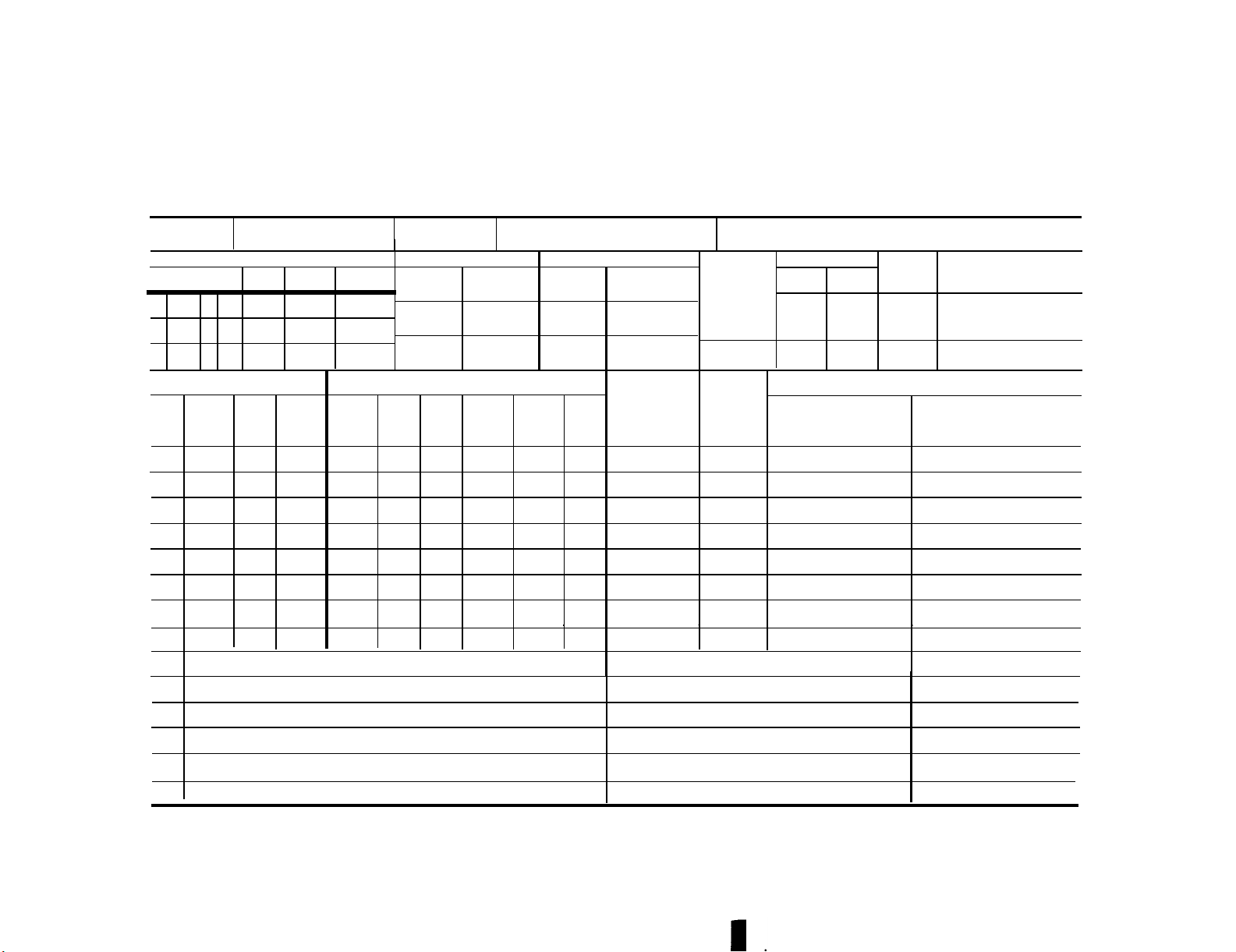
e. Maintenance of Forms. Instructions for the maintenance of forms,
records, and reports are listed in DA
PAM 738-751 and TB 55-1500-307-24. When
requires an inspection at intervals,
list the required inspection on DA Form
2408-18.
battle damage assessment and repair
(BDAR) becomes necessary, the procedures
in DA PAM 738-751 will apply. Refer to
in block 5.
Figures 1-1 and 1-2 for examples.
(1) In block 17 of DA Form
block 6.
2408-13, list the fault.
(2) In block 16 of DA Form
inspection in block 7.
2408-13, enter the status symbol.
1-11. REPORTS. All written reports
(3) In block 18 of DA Form 2408-13,
enter the corrective action taken.
required for BDAR fixes are found in DA
PAM 738-751.
longer fly, the aircraft commander
(4) The individual completing the
repair will sign the form in block 19
opposite the first line of the action
taken, and will place his last name ini-
tial over the status symbol in block 16.
should immediately initiate an out-ofaction report to his superior.
munications capability is damaged, the
aircraft commander should approach the
nearest friendly radio and make his
report if possible. The report should
f.
Temporary Repair. If the repair
include these essentials:
is temporary, take the following addi-
tional action:
a. Aircraft damage (out-of-action or
function partially impaired).
(1) In block 18 of DA Form 2408-13,
enter the corrective action and a state-
b.
ment that the repair is temporary. Then
make an entry in DA Form 2408-14, block
The entry will be a duplicate of the
b.
entry in block 17 of DA Form 2408-13 to
c. Defense status.
d.
include a statement that a temporary
repair has been made.
e. Personnel report.
(3) If the temporary repair
(a) Enter item to be inspected
(b) List the applicable TM in
(c) State the frequency of the
If the helicopter can no
If com-
Location of aircraft.
Mobility.
NOTE
Faults with status symbol of red "x", or
circle red "x" will not be entered on
DA form 2408-14.
(2) If the temporary repair limits
f.
action.
g.
time.
the capability of the aircraft, the
following entry will be made on DA Form
2408-13:
(a) Place a circled red “X” in
block 16.
(b) State the limitation in
block 17.
1-6 Change 1
Current and anticipated hostile
Anticipated BDAR fixes and repair
Page 27
TM 55-1520-228-BD
GENERAL INFORMATION
1. DATE 2 MODEL
7
1
2
3
11
SERV-
ICE
NO.
TOTAL
16
STATUS
AIRCRAFT
1
2
3
4
5
6
7
17
STATUS TODAY
ELEC-
TRONIC
4
5
6 TIME
FUEL (Gals or Lbs)
GRADE
ADDED
ARMA-
MENT
TOTAL
IN
TANKS
OTHER
12
ADDED
GRADE
FAULTS AND/OR REMARKS
N0.
ENG
3. SERIAL NO.
8
AIRCRAFT TIME
TIME TO
DATE
TIME TO-
DAY
TOTAL
OIL ( Quarts)
TOTAL
1
IN
TANKS
4 NAME OF CREW CHIEF/MECHANIC 5 STATlON
9
NEXT INSPECTION DUE
INTMED
NO.
P.E. NO.
OTHER
14
ADDED
N0. 2
ENG
TOTAL
IN
TANKS
APU
13
0XYGEN
(PSI)
18.
I
ENGINE
PREVIOUS
TODAY
TOTAL
ANTl-
ICING
FLUID
(Gals)
ACTION TAKEN
15
HOT STARTS
N0.1
NO. 2
ENGINE
BY
6 PAGE NO.
LANDINGS
b
SERVICED
19
6a NO. OF PAGES
OTHER
c
STATION
SIGNATURE
I
DA FORM 2408-13, 1 DEC 66
REPLACES EDITION OF 1 JAN 64, WHICH WILL BE USED
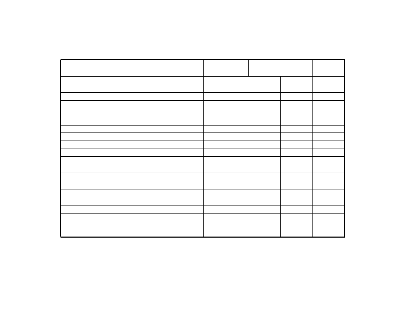
Figure 1-1. DA Form 2408-13
I
I
AIRCRAFT INSPECTION AND MAINTENANCE RECORD
For use of this form see DA PAM 738-751, the proponent army is DCSLOG
1
1-7
Page 28
TM 55-1520-228-BD
GENERAL INFORMATION
1. NOMEN CLATURE
5.
ITEM TO BE INSPECTED
2. MODEL 3. SERlAL NUMBER 4. PAGE NO.
NO. OF PAGES
6.
REEFERENCE
7.
FREQUENCY
8.
NEXT DUE
●
DA FORM 2404.18. 1 JAN 64
1-8
Figure 1-2. DA Form 2408-18
EQUIPMENT INSPECTION LIST
For use
of this form, see TM 38-750;
the proponent agency is DCSLOG.
Page 29
TM 55-1520-228-BD
GENERAL INFORMATION
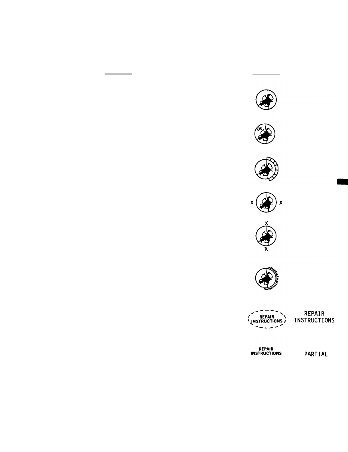
MEANINGS
TO INDICATE DAMAGE HAS BEEN ASSESSED AND EVALUATED:
Draw a circle around the damage.
TO INDICATE NO BDAR REPAIR REQUIRED:
Write “OK” inside the circle.
TO INDICATE STRUCTURAL REPAIRS ARE REQUIRED:
Draw a second line about 1/4 to 1/2
way around the initial circle then
draw slashes or crosshatch between
the two circular lines.
STRINGER REPAIR:
left and right of the circle.
FRAME REPAIR: Place an X above and
below the circle.
Place an X to the
MARKINGS
TO INDICATE DAMAGE TO SYSTEMS REQUIRING REPAIRS:
Draw a series of “curly cue” lines about
1/4 to 1/2 way around the initial circle.
TO INDICATE REPAIR INSTRUCTIONS:
For internal damage - draw a dashed
circle around the repair instructions.
For external damage - write repair
instructions but do NOT enclose
with a circle.
Figure 1-3.
Damage Assessment Markings (Sheet 1 of 3)
1-9
Page 30

TM 55-1520-228-BD
GENERAL INFORMATION
WRITTEN INSTRUCTIONS
See me -
print name &
rank. (Signature)
Names of parts to
be repaired, (item,
skin, stringer.
Full
Partial
See assessor or whoever has signed written instructions
for additional information.
Where compound damage occurs, the names or abbreviations
of specific items can be written adjacent to the damage
to clarify repair instructions.
A full strength repair is required.
Partial strength repair required in accordance with
MEANING
specific aircraft BDAR manual.
OK
No repairs required - damage is within acceptable limits
for battle conditions.
?
Continual assessment or reinspection is required after
each sortie.
Instruction markings for system are in two parts:
(1) Repair instruction markings and meanings are shown on this sheet and are
used to indicate repair actions required.
(2) System Identification - When known,
identify the system using markings
shown on sheet 3 of this figure.
MARKINGS MEANING
Fix
Repair the damaged system in accordance with approved
standard BDAR techniques for type of system, item,
high pressure, low pressure, etc.
Cap
Repl
OK
Tag
Terminate or block the system to prevent leakage.
Replace damaged part -
repairs not acceptable.
No repairs required.
Repair instructions are written on tags tied to indivi-
dual damaged lines/components.
1-10
Figure 1-3.
Damage Assessment Markings (Sheet 2 of 3)
Page 31

TM 55-1520-228-BD
GENERAL INFORMATION
System identification markings are primarily abbreviations of the system.
MARKINGS SYSTEM/MEANING
Sys
Damage to unknown system.
Fuel Fuel
Hyd
HP
LP
Elect
AV
Hydraulic
High Pressure
Low Pressure
Electrical
Avionics
Flt Cont Flight Control
Main Rotor Main Rotor Group
Tail Rotor Tail Rotor Group
Air Pneumatic
Air Cond Air Conditioning
BL Air Bleed Air System
BLC
N
2
O
2
Boundary Layer Control
Nitrogen
Oxygen
Eng Contr Engine Control
Pow Tr Power Train
EJ
Ejection
NOTE
More than one identification marking may be used to describe
the system (e.g., HP, Hyd).
Figure 1-3. Damage Assessment Markings (Sheet 3 of 3)
1-11/(1-12 Blank)
Page 32

Page 33

TM 55-1520-228-BD
CHAPTER 2
ASSESSING BATTLEFIELD DAMAGE
BDAR FIXES SHALL BE USED ONLY IN COMBAT OR FOR TRAINING
AT THE DISCRETION OF THE COMMANDER.
(AUTHORIZED TRAINING FIXES ARE LISTED IN APPENDIX E.)
IN EITHER CASE, DAMAGES SHALL BE REPAIRED BY STANDARD
PROCEDURES AS SOON AS PRACTICABLE.
Section I.
2-1. SCOPE.
a. This chapter provides guidelines
to use in assessing battlefield damage
to the OH-58 helicopter. It directs you
to an expedient BDAR fix or to the standard system fix of TM 55-1520-228-23-1,2
if an expedient BDAR repair does not
exist.
Table 2-1, assists in BDAR discussions.
b.
fault assessment chart for each functional group and this flow chart will
direct you to specific BDAR fixes for
and within the functional group.
c. Use the following guidelines to
find and fix sustained damage or
suspected damage to your helicopter.
Keep in mind that damage can be
sustained while on the ground or in
flight.
have a considerable effect on the
assessment.
shall be accomplished.
inspect and check the helicopter using
operator’s check list (CL), operator’s
manual (-10), and other records and
forms kept in aircraft log book. At
the same time be looking for obvious
damage to aircraft.
General decision logic chart,
Each chapter will have a specific
The helicopter location can
The following appraisal
(1) If possible and time permits,
INTRODUCTION
use standard troubleshooting recommendations in TMs.
mine its effect on helicopter’s mobi-
lity and capability.
with standard fixes, apply this TM and
use general and specific assessment
tables, charts, and BDAR action.
aircraft’s flying status, the aircraft
or flight commander will decide whether
to fix or defer fix, and continue or
start mission.
status, do one of the following:
serviceable part.
suitable substitute if it exists.
replace all lost fluids/lubricants. If
one specified by aircraft TM is not
available, refer to Appendix D for
alternative materials/parts.
(2) If applicable and possible,
(3) If you find a problem, deter-
(4) If you cannot fix the problem
(5) If the damage does not affect
(6) If damage does affect flight
(a) Replace damaged part with a
(b) Replace damaged part with
(c) Apply a BDAR fix.
(7) After repairing the damage,
2-1
Page 34

TM 55-1520-228-BD
ASSESSING BATTLEFIELD DAMAGE
Table 2-1. General Decision Logic
2-2
SEE TM 55-1520-328-25
Page 35

TM 55-1520-228-BD
ASSESSING BATTLEFIELD DAMAGE
d.
General aircraft assessment charts,
Table 2-1, guide you through the aircraft’s capability so that all the
necessary capabilities are evaluated.
If a fault is found, Table 2-1 directs
you to the chapter for the functional
group which contains the fault. The
BDAR assessment procedure will refer you
Section II.
GENERAL FAULT ASSESSMENT TABLE
2-2. GENERAL FAULT ASSESSMENT TABLE.
to a guide fix in this manual, a stan-
dard TM 55-1520-228-23 repair if it is
feasible, or a higher AVIM level of
repair if extent of damage, time constraint, tooling requirements, repair
part or material,
requirements are only available at a
higher level of maintenance.
Refer to Table 2-2 for assessment logic flow
chart.
Table 2-2.
General Assessment
and any other necessary
2-3
Page 36

TM 55-1520-228-BD
ASSESSING BATTLEFIELD DAMAGE
Table 2-2. General Assessment (Cont)
2-4
Page 37

TM 55-1520-228-BD
ASSESSING BATTLEFIELD DAMAGE
Table 2-2. General Assessment (Cont)
2-5
Page 38

TM 55-1520-228-BD
ASSESSING BATTLEFIELD DAMAGE
Table 2-2. General Assessment (Cont)
2-6
Page 39

ASSESSING BATTLEFIELD DAMAGE
Table 2-2. General Assessment (Cont)
TM 55-1520-228-BD
2-7
Page 40

TM 55-1520-228-BD
ASSESSING BATTLEFIED DAMAGE
Table 2-2. General Assessment (Cont)
2-8
I
Page 41

TM 55-1520-228-BD
ASSESSING BATTLEFIELD DAMAGE
Table 2-2.
General Assessment (Cont)
I
2-9/(2-10 Blank)
Page 42

Page 43

TM 55-1520-228-BD
CHAPTER 3
GENERAL REPAIRS
BDAR FIXES SHALL BE USED ONLY IN COMBAT OR FOR TRAINING
AT THE DISCRETION OF THE COMMANDER.
(AUTHORIZED TRAINING FIXES ARE LISTED IN APPENDIX E.)
IN EITHER CASE, DANAGES SHALL BE REPAIRED BY STANDARD
PROCEDURES AS SOON AS PRACTICABLE.
No general repairs have been identified
for this model helicopter. Proceed to
Chapters 4 thru 19 for functional group
assessment and repair procedures.
3-1/(3-2 Blank)
Page 44

Page 45

TM 55-1520-228-BD
CHAPTER 4
AIRFRAME
BDAR FIXES SHALL BE USED ONLY IN COMBAT OR FOR TRAINING
AT THE DISCRETION OF THE COMMANDER.
(AUTHORIZED TRAINING FIXES ARE LISTED IN APPENDIX E.)
IN EITHER CASE, DAMAGES SHALL BE REPAIRED BY STANDARD
PROCEDURES AS SOON AS PRACTICABLE.
Section I. INTRODUCTION
4-1.
information on battle damage assess-
ment and expedient repair procedures
for the OH-58 helicopter airframe.
The procedures are to be used only
during combat operations or during
periods of extreme emergency.
pertaining to the various structural
areas which are suspected of being
damaged, and whether the damage is to a
primary or secondary element. Logic
flow chart tables and damage limit
tables are also part of this section.
structural repairs and procedures on
how to perform these repairs and field
fixes.
4-2. ASSESSMENT PROCEDURES. Refer to
Table 4-1.
4-3. GENERAL. Aircraft structure is
classified as primary and secondary
structure.
SCOPE. This chapter contains
a. Section I contains information
b.
Section II consists of expedient
however, secondary structure may be
required for aerodynamic reasons or to
accomplish or support mission functions.
4-4. STRUCTURAL DAMAGE ASSESSMENT AND
REPAIR.
damage assessment and repair consists of
three steps:
paragraph 4-5; a detail assessment,
paragraph 4-6; and a repair plan,
paragraph 4-10.
is a quick visual assessment to decide
whether or not a detail assessment
should be made.
involves the identification of all
damage to primary structural elements,
possibly some clean-up and measurement
of the damage and of the damaged ele-
ments.
various aircraft sections in this
chapter. This process requires damage
measurement and determination of the
corresponding damage limits.
plan is based on an analysis of the
detail assessment.
all the aircraft zones is shown in
Figure 4-1.
The battlefield structural
an initial assessment,
The initial assessment
A detail assessment
The procedure is described for
The repair
An overall view of
a. The primary structure is the basic
structure which holds the aircraft
together.
element of the primary structure will
restrict the combat capability of the
aircraft. The primary structure for
each major airframe subassembly is
shown in Figure 4-11, Sheets 1 thru 5.
b.
Secondary structures are mounted
on the primary structure.
of structural damage to secondary structures will restrict combat capability
from a structural point of view;
Any serious damage to any
No amount
4-5.
initial assessment, the assessor must be
acquainted with structural damage modes
and the primary structure as shown in
the figures of this chapter. He shall
be capable of differentiating between
primary and secondary structure, and he
must understand the function of primary
structural elements.
ment consists of a visual inspection of
primary structure. The assessor determines if any primary caps, webs, or
panels are damaged or fractured and
decides whether:
INITIAL ASSESSMENT. To perform an
The initial assess-
4-1
Page 46

TM 55-1520-228-BD
AIRFRAME
Table 4-1. Aircraft Structure Damage Assessment Prodecures
4-2
Page 47

TM 55-1520-228-BD
AIRFRAME
Figure 4-1. Aircraft Sections
4-3
Page 48

TM 55-1520-228-BD
AIRFRAME
the damage appears to be
a.
deferrable;
b.
a detail assessment can be made
and the damage can be repaired by BDAR
techniques within the time available to
return the aircraft to service in the
ongoing battle;
c .
and the damage can be repaired by BDAR
techniques to enable the aircraft to
self-recover;
made and/or the damage cannot be re-
paired by BDAR techniques within the
available time. The aircraft shall be
scheduled for standard repair.
repair, and he shall arrange for its
disposition (i.e., recovery, cannibalization, or destruction).
4-6.
Locate all damage to airframe primary
structure.
covers, and fairings in the damaged
area.
required to inspect the structure.
the location of entrance and exit wounds
and the estimates of projectile paths to
determine the areas where damage may be
present and access to interior inspec-
tion will be needed. If an area of
structure suspected of being damaged
cannot be reached by other means, cut
small inspection holes in the exterior
skin. Then inspect internal members
with an inspection light and mirror.
an adequate assessment can be made
d.
a detail assessment cannot be
e. The aircraft is damaged beyond
DETAIL ASSESSMENT.
a. Access to Damaged Structure.
Remove access panels,
Remove aircraft components as
Use
b.
Inspecting for Cracks.
cracks caused by projectile damage.
Small cracks will enlarge under continued loading, particularly when
located at the edge of a hole.
structure using magnifying glass or dye
penetrant.
fasteners in areas showing signs of
overstress.
areas of an explosion caused by a high
explosive incendiary (HEI) strike.
c.
surrounding undamaged area for evidence
of buckling, crippling, and misalignment. Kinks, wrinkles, and sheared,
pulled-through or missing fasteners on
skin panels are indications of structural changes by an HEI hit.
the form of buckling, crippling, and
misalignment caused by overpressure.
These structural changes are noticeable
in areas where one structural member may
have to support the load of another
broken member. Check damaged area to see
if there is interference with mechanical
moving components.
the component for twisting or bowing.
d.
Projectiles and Fragments.
tiles which can create the same affect
as a hole or crack on a tension member.
(2) Inspect for small and large
(3) Locate cracks in primary
Check for cracks around
(4) Inspect for cracks in all
Inspecting for Structural Changes.
(1) Inspect damaged area and
(2) Inspect structural changes in
(3) Use a straight edge to examine
Inspecting for Embedded
(1) Inspect for embedded projec-
(1) Inspect for cracks caused by
impact or penetration in regions away
from the site of primary damage.
4-4
tiles and fragments in areas which have
suffered HEI damage. The inspection
will reveal that a solid projectile is
embedded or has broken apart, striking
internal components.
(2) Inspect for embedded projec-
Page 49

(3) Inspect all structures using
bright light and magnifying glass.
Determine the path entry of the projectile to aid in finding structures that
may have embedded fragments.
embedded objects and record them on DA
Form 2404, Figure 4-2.
Inspecting for Fire Damage.
e.
Inspect for fire damage by checking for
discoloration of the structure.
discoloration will indicate that the
member has been exposed to high temperature.
determine if the temperature of the
material has changed.
heat damage, record the information on
DA Form 2404 and clearly mark the
member.
f.
Adjoining Areas.
(1) Secondary damage can be the
result of severe overstress, explosive
blast, or maneuvering loads imposed on
damaged structures. Inspect the
airframe near the projectile damage for
evidence of secondary damage.
(2) Inspect the skin for creases,
wrinkles, and dents.
for chipped or flaked paint, looseness,
and serviceability.
are evident, remove access panels and
doors to inspect members for cracks and
structural changes.
Conduct a hardness test to
If test indicates
Detecting Structural Damage in
Inspect fasteners
If these conditions
Mark
Any
i.
Refer to Table 4-1 for repair/referral of
repair on structural member.
section containing the damaged element,
Figure 4-1.
damage element such as frame, stringer,
or skin panel.
the damaged element such as station,
waterline, butt line, or panel location.
element using terms such as hole, crack,
or buckle.
for:
element.
the same subassembly.
assemblies in the section of the
airframe.
the airframe as required.
TM 55-1520-228-BD
AIRFRAME
Marking and Recording Damage.
(1) Record all detected damage.
(a) Record name of aircraft
(b) Record the name of the
(c) Describe the location of
(d) Describe the damage to the
(e) Continue damage recording
1 Other damages to the same
2 Other damaged elements in
3 Other damaged sub-
4 Other damage sections of
Inspecting for broken and missing
fasteners. Inspect fasteners for
security, shear, pull-through, tear-out,
and elongated fastener holes.
possible, inspect fasteners from both
sides.
Inspecting for Delaminations.
h.
Inspect honeycomb structures for voids
and delamination using the coin tapping
method.
Where
is completed, file the damage report in
the aircraft log book and make entries
as required.
location and extent of damage as shown
in the diagrams in Figure 1-3. The
damage can be drawn by hand. Accurately
locating damage on a diagram will
greatly help the damage assessment
procedure.
(f) After the damage inspection
(2) Damage diagrams. Show the
4-5
Page 50

TM 55-1520-228-BD
AIRFRAME
4-6
Figure 4-2.
DA Form 2404
Page 51

TM 55-1520-228-BD
AIRFRAME
(3) Marking damage. Mark the
damaged structure using grease pencil or
paint.
Use the labeling scheme shown in
Figure 1-3.
CD is the depth of the damage into the
flattened cross section. The length of
the remaining effective cross section
is still capable of supporting a load.
All dimensions are in inches.
CAUTION
Use of lead pencil in some areas
will cause corrosion.
following procedure:
(a) Use a bright color to
outline each area of damage as it is
located and recorded on the DA Form
2404.
Attempt to make the outline
visible from all angles.
thoroughly. Use brushes and swabs to
remove dirt and film from small crevices
where damage may be present.
(b) Draw arrows on inside skin
panels, webs, and bulkheads to point
toward areas of damage that are hidden.
edges and be sure to cut out all radiated
cracks. Use largest corner radii possible
in the cut-outs; avoid sharp corners.
4-7.
DAMAGE MEASUREMENT. If the
assessment indicates that the damage
should be repaired by BDAR or standard
procedures, no damage measurement is
necessary. Damage measurement is
required to determine if structural
smoothing, or if measuring before
smoothing, make allowance for the
material which must be removed during
smoothing.
repair (other than cleanup) can be
deferred, or if self-recovery of the
damaged aircraft is feasible. Damage
measurement may also be required if a
in tenths of an inch and measure each
damage dimension to the next higher tenth.
BDAR repair does not restore original
strength.
with the largest damage.
Begin damage measurement
hole when measuring damage that extends
into a fastener hole or lightening hole.
a. Damage Measurement of Typical
Sections.
CS = (a+b)-CD
(2) When measuring damage, use the
(a) Clean all damaged areas
(b) Smooth all jagged and rough
(c) Measure damage after
See paragraph (d) below.
(d) Use a steel rule graduated
(e) Include the size of the
(f) Record on DA Form 2404.
(1) The parameters involved in
measuring damage to typical sections
are shown in Figure 4-3. The per-
tinent values are:
for the measurements of “WL” and “D.”
"WL" is the largest dimension across the
CD
= Depth of damage.
CL = Length (width) of damage.
A = CL x CD =
Distance between damages.
D =
area of damage.
damage, regardless of direction, and
must include all radiated cracks.
is the distance between damages. Take
and record measurements as described in
paragraph 4-7.a(2).
In Figure 4-4, the length of the flattened cross section of the angle is:
a+b
Webs, Panels, and Skins.
b.
(1) Refer to Figures 4-5 and 4-6
"D"
4-7
Page 52

TM 55-1520-228-BD
AIRFRAME
4-8
Figure 4-3.
Evaluating Damage to Angles, Channels, and Z-Angles
Page 53

TM 55-1520-228-BD
AIRFRAME
Figure 4-4.
Damaged Cross Section
4-9
Page 54

TM 55-1520-228-BD
AIRFRAME
4-10
IMPORTANT: MEASURED LATERAL DAMAGE MUST
INCLUDE ALL RADIATED CRACKS.
Figure 4-5. Measuring Skin Panel Damage
Page 55

TM 55-1520-228-BD
AIRFRAME
Figure 4-6.
Measuring Damage in Webs and Panels
4-11
Page 56

TM 55-l52O-228-BD
AIRFRAME
(2) Honeycomb Sandwich Structures.
Refer to Figure 4-7 for the measurement
of "WL" and "D." If a projectile hits
a sandwich panel at an angle, the
damages in the two skins may be off-set
and of different sizes.
damage on the side with the largest
damage (usually the exit side), and make
sure that the measurement includes the
damaged area on the other side. "WL" is
the largest dimension across the damage
(both sides), regardless of direction,
and must include all radiated cracks.
“D” is the distance between damages.
Take and record the measurements as
described in paragraph 4-7.a(2).
c.
Fittings, Attachments, and
Splices.
(1) See paragraph 4-12.
(2) Record all damage on DA Form
2404, Figure 4-2.
d.
Damage measurements apply after
cleanup and smoothing or after BDAR has
been accomplished.
tical matter, measurements must be taken
before smoothing to make a decision on
deferrability.
damage limits before cleanup and smooth-
ing, make allowance for the material
that will be removed in smoothing. This
applies particularly to cracks.
length of the crack must be included in
in the depth (CD) and length (CL)
measurements.
4-8. ALLOWABLE DAMAGE LIMITS DEFINITION.
a. The allowable damage limits
corresponding to the damage measurements
of paragraph 4-7 are designated for a
given condition as follows:
Hence, when estimating
Measure the
However, as a prac-
The
CD'
CL'
A'
D'
WL'
N
b.
mary structural elements are associated
with the conditions of paragraph 4-9. A
damage limit for a given condition is a
measure of the amount of damage that a
structural member can sustain and still
support the loads associated with the
given condition.
c. For a given condition, all damages
must be equal to or less than the
corresponding allowable damage limits,
and the distance between damages must be
equal to or greater than the
corresponding minimal allowable limit;
that is:
The aircraft may be released for flight
in that condition. Repair may be
deferred, although some cleanup and
smoothing of the damage will be
required, as will inspection for damage
growth after every flight. Special consideration should be given to damage
exposed to the airstream, particularly
to the effects of ram air, rain, and
petaling.
passing airflow, rapidly creating cracks
in the supporting base metal.
pieces of metal may peel off and damage
other parts of the aircraft. The
distance D between damage sites for most
structures has a minimum required
spacing.
expressed as a multiple factor (N) of the
measured area of damage.
= Allowable depth of damage.
= Allowable length (width) of
damage.
= Allowable area of damage.
= Minimum allowable distance
between damages.
= Allowable largest dimension
across web/panel damage.
= Minimum damage factor.
Allowable damage limits for pri-
CD < CD'
CL < CL'
WL < WL'
D>D'
Petals may vibrate in the
Large
The spacing requirement is
4-12
Page 57

TM 55-1520-228-BD
AIRFRAME
Figure 4-7.
Measuring Damage in Honeycomb Sandwich Panels
4-13
Page 58

TM 55-1520-228-BD
AIRFRAME
(1) The factor applies to the
damage actually measured not to the
maximum damage limit for the structure.
(2) The factor applies to the
largest dimension of the largest damage
between which separation is being
measured.
(3) The factor applies only if the
dimensions of both damages, when added
together, exceed the single damage
limit.
4-9.
cator of the residual capacity of a
damaged structural element to perform
its function. Battlefield damaged
structures or BDAR repaired structures
are classified in three conditions:
flight capable.
However, on a battlefield under the
pressures of time and tactical situations, the assessment of structural
damage may not have found all the damages.
tural damage, whether repaired or repair
deferred, should be inspected after
every flight.
look for crack growth, evidence of
overstress, growth of allowable deformations, and for the development of new
cracks at other locations.
capable.
to move a damaged aircraft to a repair
site or from one site to another when
towing is not feasible. Self-recovery
is preferable to disassembly and boxing
an aircraft for transportation.
permits, proceed as follows:
the extent of other structural damage
with chalk, grease pencil, paint, tape,
or other available means so that any
growth in the damage can be quickly
recognized.
CONDITION.
Condition 1.
a.
Therefore, aircraft with struc-
b.
Condition 2.
Self-recovery may be required
(1) Mark all visible cracks and
Condition is an indi-
Aircraft fully
No flight restrictions.
The inspector should
Self-recovery
As time
on-site BDAR fixes as required for
self-recovery.
weapons, stores, and unnecessary equipment.
are imposed on a recovery flight:
2 hours.
pedal movements
aircraft.
soft touchdown from hover.
c.
exceeding condition 2 limits generally
does not allow self-recovery. The
damage may or may not be repairable by
BDAR techniques. The airframe may be so
extensively damaged that no useful or
needed functions can be restored within
available time and resources. These
aircraft will be:
facility with the resources to repair
the airframe.
ized components.
resort. These conditions apply to the
primary structure and should not be con-
fused with the mission capability
classifications. Mission capability is
dependent on equipment condition.
(2) Perform any feasible
(3) Unload all ammunition,
(4) The following restrictions
(a)
Maximum airspeed: 50 kts
Maximum engine torque:
(b)
80% at O kts
64% at 16 kts
53% at 32 kts
50% at 50 kts
Maximum flight time:
(c)
(d)
Use gradual and smooth
to minimize loads on
(e)
Land at level attitude;
Condition 3.
(1) Recovered or evacuated to a
(2) Used as a source of cannibal-
(3) Destroyed. This is a last
Structural damage
4-14
Page 59

d.
The type, extent, and variation of
damage under condition 3 does not per-
mit categorization of the many com-
binations of damage. Self-recovery, if
considered, will depend on the extent
and type of damage, type of terrain,
distance, and urgency of the situation.
If judgment and experience indicate
self-recovery is feasible, it should be
accomplished at minimum weight, altitude
and airspeed with an occasional stop to
check on the condition of the aircraft.
4-10. REPAIR PLAN.
a. The damage measurements and initial repair data obtained from the
detail assessment must be organized and
formulated into a repair plan.
b.
Repair requirements including
cleanup/smoothing, condition, and
repair times should be recorded on DA
Form 2404.
c. If the worst case is better than
condition 1, repair may be deferred
except for cleanup and smoothing of all
rough edges. The ends of all cracks
must be stop drilled.
d.
If the worst case is between
condition 1 and 2, a decision must be
made to degrade the aircraft to
condition 2 or to repair the aircraft
and restore it to condition 1.
(1) If the aircraft is degraded to
condition 2 and is to perform a recovery
flight, severe damage should be cleanedup, rough edges smoothed, and cracks
stop drilled.
(2) If it is decided to restore
the aircraft to condition 1,
(a) determine the required
repairs for all damaged structural
elements that are below condition 1.
tural elements that are better than
condition 1 may be deferred except for
cleanup and smoothing.
e. If the worst case is between
condition 2 and 3, a decision must be
made to degrade the aircraft to
condition 3 or to repair the aircraft
and restore it either to condition 1
or 2. An aircraft in this condition is
probably so badly damaged that it may
not be restored to condition 1 within
the available time.
effort should be made to restore it to
condition 2 or better if at all possible
for recovery.
condition 3, no repair is required.
the aircraft to condition 2,
repairs for all damaged structured
elements that are below condition 2.
tural elements that are better than
condition 2 may be deferred except for
some cleanup and smoothing of the badly
damaged areas.
the aircraft to condition 1,
repairs for all structural elements that
are below condition 1.
tural elements that are better than
condition 1 may be deferred except for
cleanup and smoothing.
f.
repair plan formulated, complete repairs.
Attach DA Form 2404 to DA Form 2408-13
and indicate deferred repairs on DA
Form 2408-13.
TM 55-1520-228-BD
AIRFRAME
(b) Repairs on damaged struc-
However, every
(1) If the aircraft is degraded to
(2) If it is decided to restore
(a) determine the required
(b) Repairs on damaged struc-
(3) If it is decided to restore
(a) determine the required
(b) Repairs on damaged struc-
Once all decisions are made and a
4-15
Page 60

TM 55-1520-228-BD
AIRFRAME
4-11.
main sections. The forward cabin sec-
tion extends from the cockpit nose at
FS1 to the bulkhead aft of the passenger
compartment at FS130. The aft cabin
section extends from FS130 to FS205
where the tail boom is attached. The
third section is the tail boom. Refer
to Figure 4-8.
minum honeycomb and sheet metal structures for the major load carrying
elements.
for pilot and passenger seating, fuel
cell enclosure, and pylon support.
Honeycomb sandwich is used extensively
in this section, including the upper and
lower shells, seat panels, and some
bulkhead panels.
conventional thin sheet metal construction.
taken by the lower console, pedestal,
and lower shell.
section between FS73 and FS130 is a X -
Z planar frame consisting of the center
post at FS73, roof beam, lower shell,
and bulkhead and enclosure at FS114 and
FS130.
num and honeycomb semimonocoque construc-
tion and provides a deck for engine
installation and a compartment under the
engine deck for electrical equipment.
This section utilizes conventional thin
sheet metal structure composed of
longerons and bulkhead frames as beam
elements and decks and skins as shear
panels. Some of the fairing and decks
are honeycomb panels.
tion with a horizontal stabilizer, vertical fin, and anti-torque rotor
attached.
coque structure utilizing a tapered circular section of aluminum alloy skin.
Redistribution in the forward end, which
is required to transfer loads from the
GENERAL.
a. The aircraft consists of three
b.
The forward section utilizes alu-
The forward section provides
The remainder is of
Primary loads forward of FS73 are
The cabin enclosure
Refer to Figure 4-9.
c. The aft section utilizes an alumi-
The tail boom is a circular sec-
d.
The tail boom is a full mono-
monocoque structure to the four attachment fittings on the fuselage, is
accomplished by the use of intercoastals
and two aluminum redistribution
bulkheads. The horizontal stabilizer
is a standard spar-rib-skin riveted
construction. The vertical fin is of
standard sandwich construction using
aluminum honeycomb core and thin
aluminum skins. The upper half of the
upper fin is composed of fiberglass skins
and honeycomb core.
e. The damage assessment procedure
described in paragraph 4-5 consists of
damage measurement, determination of the
corresponding allowable damage limit and
associated condition, and formulating
repair instructions. This data is
recorded on DA Form 2404.
4-12.
a. Refer to Figures 4-8 thru 4-15 for
location and identification of major
fuselage and tail boom structural areas.
b.
each damaged element, measure the depth
“CD” and the length (width) “CL” or “WL”
of each damage.
damages and measure the “D” between
damages. Start with the worst damage.
Record these values for each damaged
element on DA 2404 and compare them with
the allowable damage limits given in
this section. Select the set of
allowable damage limits which are next
larger than the measured damage, determine the corresponding condition.
Consider whether damage could result in
flight failure of other elements.
Attempt to visualize what effect large
defections of damaged member will have
on adjacent structure.
c. Decide on whether repair can be
deferred or whether damage should be
fixed and what the condition of deferred
or repaired damage would be.
DAMAGE MEASUREMENT.
Refer to paragraph 4-8 and for
Count the number of
4-16
Page 61

TM 55-1520-228-BD
AIRFRAME
Figure 4-8.
OH-58 Helicopter
4-17
Page 62

TM 55-1520-228-BD
AIRFRAME
PROFILE
BL -
BUTT LINE
FS -
FUSELAGE STATION
CENTER TAILROTOR BEARING HANGER.
●
TANGENCY POINT.
CONTOURS IN BOOM STATIONS ARE
CIRCLES.
WL -
WATERLINE
RADIUS AT 182.405 IS 3.286". TAPER'
OF BOOM IS 0.02703" PER INCH. BOOM
- BOOM STATION (UNDERLINED)
BS
STATION IS 90° TO HORIZ C BOOM.
Figure 4-9. Airframe Reference Lines
RADIUS AT 31.87 IS 7.3555"
4-18
Page 63

TM 55-1520-228-BD
AIRFRAME
Figure 4-10. Cockpit
4-19
Page 64

TM 55-1520-228-BD
AIRFRAME
4-20
Figure 4-11.
Fuselage Pylon Support Structure (Sheet 1 of 5)
Page 65

TM 55-1520-228-BD
AIRFRAME
Figure 4-11.
Fuselage Pylon Support Structure (Sheet 2 of 5)
4-21
Page 66

TM 55-1520-228-BD
AIRFRAME
4-22
Figure 4-11.
Fuselage Pylon Support Structure (Sheet 3 of 5)
Page 67

FUSELAGE STA 130
BULKHEAD
TM 55-1520-228-BD
AIRFRAME
FS130
FS117.71
WL 21.00
Figure 4-11.
Fuselage Pylon Support Structure (Sheet 4 of 5)
4-23
Page 68

TM 55-1520-228-BD
AIRFRAME
4-24
Figure 4-11.
Fuselage Pylon Support Structure (Sheet 5 of 5)
Page 69

TM 55-1520-228-BD
AIRFRAME
Figure 4-12.
Upper and Lower Shell Structure
4-25
Page 70

TM 55-1520-228-BD
AIRFRAME
4-26
Figure 4-13.
Aft Fuselage Structure
Page 71

TM 55-1520-228-BD
AIRFRAME
Figure 4-14. Tail Boom
4-27
Page 72

TM 55-1520-228-BD
AIRFRAME
4-28
Figure
4-15.
Cowling and Firewalls
Page 73

TM 55-1520-228-BD
AIRFRAME
d.
Determine the priority of the
various required repairs based on repair
time, difficulty of repair, resources
available, tactical situation, and need
for the aircraft, etc. The longest
repair time normally is given the
highest priority and is most critical.
4-13. ALLOWABLE DAMAGE LIMITS. Damage
limits are calculated on the basis of
the OH-58 structural analysis and tend
to be conservative. Assessors using
damage limits to prepare damage
assessments should consider them as
guides and balance the damage limits
against the judgment resulting from
their own experience.
a. Damage limits are tabulated in
Tables 4-2 thru 4-7 for most primary
structure.
covered in this manual and the damage
appears to exceed authorized limits,
classify the member as unserviceable.
A component that shows signs of
b.
severe overstress such as twisting or
buckling or heat damage should be
treated as failed.
A component should be repaired if
c.
the failed component can overstress
other systems.
Evaluation of Damage to Caps,
d.
Longerons, and Stringers.
caps,longerons, and stringers as failed
if any of-the following conditions
exist:
(1) Damage exceeds limits
tabulated in Tables 4-2 thru 4-7.
(2) There is damage in four or
more locations within a length of three
feet.
(3) Fasteners securing the com-
ponent to other major components are
sheared, pulled-through, or missing at
one or more locations.
If a damaged member is not
Classify
to each other, which join a cap,
longeron, and stringer to the web, are
sheared, pulled-through or missing.
component to web fasteners are similarly
damaged.
component to another structure are
severely damaged or failed.
e. Evaluation of Damage to Machined
Fittings. Classify a fitting as failed
if any of the following conditions exist:
the limits contained in Tables 4-2
thru 4-7, or if damage is not tabulated
and exceeds 20 percent of the structural
section in any one location.
necting the fitting to a structure or to
an aircraft component are bent, sheared,
stripped, or loose.
f.
Doublers, and Gussets. Damage to a
splice, strap, doubler, and gusset will
be evaluated as part of the elements to
which it attaches. Classify a splice,
strap, doubler, or gusset as failed if
any of the following conditions exist:
tained in Tables 4-2 thru 4-7, or if
damage is not tabulated and exceeds 20
percent of the structural section in
any location.
damage at the intersection of the two
members it connects.
a structural member(s) are sheared,
pulled-through, or missing at two or
more adjoining locations.
total number of fasteners are similarly
damaged.
(4) Three or more fasteners next
(5) Twenty percent or more of the
(6) Angles and clips securing the
(1) Damage to the fitting exceeds
(2) One or more fasteners con-
Evaluation of Splices, Straps,
(1) Damage exceeds the limits con-
(2) The part has significant
(3) Fasteners securing the part to
(4) More than 20 percent of the
4-29
Page 74

TM 55-1520-228-BD
AIRFRAME
g.
Evaluation of Damage to Skin and
Web Panels.
panel as failed if any of the following
conditions exist:
(1) Damage exceeds the limits con-
tained in Tables 4-2 thru 4-7, or if
damage is not tabulated and exceeds 25
percent of the panel area.
(2) Damage to one panel is located
within 3 inches of damage in an adjoin-
ing panel.
(3) The panel is severely deformed
or buckled.
(4) Damage to a panel exceeds the
damage limit.
a stringer, frame, or former in an adjoining panel. Classify that panel as
failed even if its damage is within
limits.
(5) The panel is on the outside of
the aircraft where the damage is exposed
to aerodynamic forces that can produce
peeling or tearing of the structure in
flight.
(6) Fasteners securing the panel
are sheared, pulled-through, or missing
at three or more adjoining locations.
(7) Twenty percent or more of the
total number of fasteners are similarly
damaged.
Classify a skin or web
The damage extends across
oriented so as to produce peeling or
tearing of the structure in flight.
nical fasteners. Three or more
adjoining fasteners are sheared, pulledthrough, or missing.
total number of fasteners are similarly
damaged.
i. Evaluation of Damage to Sheet
Metal Ribs, Formers, Intercoastals, and
Channels. Classify a rib, former,
intercostal, or channel as failed if
any of the following conditions exist:
tained in Tables 4-2 thru 4-7, or if
damage is not tabulated and exceeds 25
percent of the structural section.
ponent are sheared, pulled-through, or
missing in three or more adjoining locations.
total number of fasteners are similarly
damaged.
j.
Doors, and Door Jambs. Classify a
damaged hatch, door, or door jamb as
failed if any of the following con-
ditions exist:
(4) The panel is secured by mecha-
(5) Twenty percent or more of the
(1) Damage exceeds the limits con-
(2) Fasteners securing the com-
(3) More than 20 percent of the
Evaluation and Damage to Hatches,
h.
Evaluaton of Damage to Honeycomb-
Sandwich Panels.
sandwich structure as failed if any of
the following conditions exist:
(1) Damage exceeds limits
tabulated in Tables 4-2 thru 4-7.
(2) The panel is damaged to the
extent that it cannot support the weight
of personnel,
which it was designed.
(3) The panel is on the outside of
the aircraft where it is exposed to
aerodynamic forces, and the damage is
4-30
Classify a honeycomb-
cargo, or equipment for
tabulated Tables 4-2 thru 4-7.
door jamb prevents it from being secured
adequately to the airframe.
and in danger of becoming unserviceable
in flight.
of severe overstress such as buckling or
misalignment.
(1) Damage exceeds limits
(2) Damage to the hatch, door, or
(3) Hinges and latches are damaged
(4) The hatch or door shows signs
Page 75

TM 55-1520-228-BD
AIRFRAME
COMPONENT/
MEMBER
Console,
Forward
FS
1.00-
32.75
1.00-
32.75
32.75- 21.00-
55.10
32.75-
44.00
32.75-
44.00
Honeycomb
Panel
44.00-
57.10 32.50
44.00- 21.00-
57.10
Instrument
Panel
Shroud
21.25-
37.57
Front
Seat
Support
57.11
Pilot's &
Copilot's
Seat
57.11-
74.54
Center
Bulkhead
Section
73.04
Center
Bulkhead
Section 73.04
Pilot’s &
Copilot’s
73.04
Collective
Jackshaft
Pedestal
Structure
73.04
55.14-
73.04
Table 4-2. Dam
LOCATION
WL
20.00-
44.50
20.00-
44.50
BL
5.06R-
3.06L
5.06R-
3.06L
5.06R-
32.50
23.39-
32.50
21.00-
3.06L
5.06R-
3.06L
5.06R-
23.39 3.06L
21.00-
5.06R-
3.06L
5.06R-
32.50
44.15-
3.06L
5.02R-
51.95 3.02L
21.00-
30.41
19.45L-
30.41
22.15R
30.29-
54.89
21.00-
30.29
10.65-
17.31L&R
30.29
21.00-
30.29
20.00-
30.17
5.06R-
3.06L
age Limits Forward Fuselage - Condition I
DAMAGE LIMITS
ELEMENT CAP/FLANGE
CD '
Caps, Stiffeners,
Doublers
Skins/Webs
CL' N
(D’=NxCL) (D'=NxWL)
1.05 2.10 10
SKIN/WEB
WL '
N
2.5 5
NOTES/CAUTIONS
Caps, Stiffeners,
Doublers
Skins/Webs
0.15 0.30 10
2.5 5
No Damage
Skin
Honeycomb Panel
Panel Edges
Brace
Honeycomb
Bulkhead
Honeycomb Panel
Web
Vertical
Stiffeners
0.20 0.40 10
1.25 2.50 10
2.0 4.0 -
Allowed
7.50 5
No Damage
Allowed
3.5 5
10.0
5 Behind Pilots
Sum of Damage
on All Elements
Aft Attachment
Angle No Damage Permitted
Support Bracket
Channel
Webs
0.70 1.50 10
0.75 5
4-31
Page 76

AIRFRAME
4-32
T M 55 -1 520-228 -BD
Table 4-2. Damage Limits Forwar d Fuselage — C ondition I (Cont)
COMPONENT /
LOCATION
MEMBER
FS
73.04
Lower Shell 36.00-
73.04
WL BL
20.00-
30.17
20.00-
25.25
5.06R-
3.06L
36.00-
73.04 20.00
12.16&
73.00 20.00
Center Post
73.00-
87.85
73.00-
87.85
74.52-
81.30
80.00-
87.85
73.00-
87.85
Passenger Seat 96.44-
1 14.76
96.441 14.76
96.44
96.441 14.76
Gun Mounts
103.76 30.25
20.00-
72.00
27.48-
72.00
54.50-
72.00
62.00-
72.00
20.00-
72.00
29.92-
31.42
24.70-
29.92
20.00-
29.92
20.00-
29.92
14.58L&R
3.00L-
3.00R
3.00L-
3.00R
3.00L-
3.00R
3.00L-
3.00R
3.00L-
3.00R
24.14L-
24.14R
23.08L&R Honeycomb Side
23.08L-
23.08R
23.08L-
23.08R
0.00&
23.00L
Depression Stop
Attachment 104.55 30.25 5.85L
DAMAGE LIMITS
ELEMENT
Caps/Stiffeners
CAP / FLANGE SKIN / WEB
CD’ CL’
N WL’ N
(D’=N x CL) (D’=N x WL)Pedestal Structure 55.14-
0.65 1.30 10
Honeycomb Panel
Inserts for Cyclic &
Pedal Controls
Forward Landing
Gear Attachments
Caps
Side Webs and
Doublers
Web, Front
Splices
Stiffeners
No Damage Within 3” Radius of Insert
One Damaged Insert Permitted
0.25 0.50 10
0
- -
0.50 1.00 10
3.50 5
2.25
0
5
—
Honeycomb Seat
Panel
Panels
Honeycomb Front
Panel
Angles, Side, Front
Top, Bottom
Fittings and
Fasteners
0.25 0.50 10
No Damage Permitted (If Used)
4.25 5
1.5 5
4.0 5
Honeycomb Panel No Damage Permitted Within 3” Radius
of Attachments
NOTES /
CAUTIONS
No Damage Within
3” of Gun Mounts
(If used)
Page 77

Table 4-2. Damage Limits Forwar d Fuselage — C ondition I (Cont)
COMPONENT /
MEMBER
1 14.79-
Back Bulkhead
122.20
1 17.90-
122.20
1 15.10-
1 17.70
1 14.76-
1 17.70
Bulkhead FS130,
Upper 130
130
130
Bulkhead FS130,
Lower 130
130
LOCATION
FS WL BL
31.42-
72.00
48.25-
72.00
35.39-
49.98
17.80L
17.80R
31.42-
49.98
51.72-
72.00
51.72-
72.00
51.72-
72.00
29.70-
51.52
20.00-
29.70
ELEMENT
Flanges, Angles,
Caps, Splices, Clips
Web
Honeycomb Door
Assembly
Honeycomb Panel
Assembly
Inboard, Outboard
Frame Caps
Frame Webs
Clips, Splices,
Supports, Flanges
Honeycomb Panel
Honeycomb Panel
DAMAGE LIMITS
CAP / FLANGE SKIN / WEB
CD’ CL’ N WL’ N
(D’=N x CL) (D’=N x WL)Passenger Seat
No Damage Permitted
1.10 5
3.00 5
1.50
1.50
0.30 0.60 10
2.40 5
0.30 0.60 10
8.00 5
3.00 5
NOTES /
CAUTIONS
5
5
4-33
Aft Cabin
Enclosure
120.00-
130.00
1 17.71-
130.00
1 17.71-
130.00
1 17.71-
130.00
1 17.71-
130.00
50.04-
69.00 20.55L&R
50.04-
67.20 25.25L
50.04-
67.20 25.25R
50.00-
72.00
25.25L&R
50.04-
72.00
25.25L&R
Inner Skin and
Doublers
Outer Skin
Outer Skin and Door
Panel
Intercoastals
Between Inner &
Outer Skin
Angles, Supports,
Flanges, Stiffeners
0.50 1.00 10
3.70 5
6.00
6.00 5
1.50 5
5
AIRFRAME
TM 55-1520-22 8-BD
Page 78

AIRFRAME
4-34
T M 55 -1 520-228 -BD
Table 4-2. Damage Limits Forwar d Fuselage — C ondition I (Cont)
COMPONENT /
MEMBER
Enclosure
FS
120.00-
130.00
LOCATION
WL BL
63.71 20.00L
ELEMENT
Gun Mount Channel
CAP / FLANGE SKIN / WEB
CD’ CL’
(D’=N x CL) (D’=N x WL)Aft Cabin
1.00 2.00 10
DAMAGE LIMITS
N WL’ N
Pylon Support 98.80 73.93 7.52L&R Forward Support No Damage Allowed
123.62 71.92 6.25L&R Aft Support No Damage Allowed
Cabin Roof Beam 80.46-
130.00
101.67&
123.62
120.90
80.46-
130.00 67.92
Lower Cabin Shell
73.181 13.00
73.181 13.00
67.92-
71.96 3.00L&R
67.92-
0 Bulkheads Between
71.96
67.92-
71.96
3.00L-
3.00R
3.00L-
3.00R
20.00-
25.25
18.40L&ROutboard
18.40L-
18.40R
Beam, Left and Right
Beams
Bulkhead Skin and
Doubler
Bottom Skin and
Access Cover
Radius and Edge of
Honeycomb Panel
Honeycomb Panel
No Damage Allowed
No Damage Allowed
2.00 5
0.75 5
1.00
6.30 5
20.00
1 13.00-
130.00
20.00-
54.65
Honeycomb Panel
6.30 5
96.44 20.00 Splice 0.75 1.50 10
Upper Cabin Roof
Shell
36.00-
130.00
54.48-
82.86
82.86-
125.00
120.40-
130.00
125.00-
130.00
20.00-
54.65
14.12L&ROutboard
14.12L-
14.12R
Frames, Angles,
Stiffeners
Top Skin
Honeycomb Panels
Honeycomb Panels
Titanium Panel
0.50 1.00 10
3.00 5
3.00 5
2.50 5
2.50 5
NOTES /
CAUTIONS
5
No Damage
Within 3” Radius
of Inserts
No Damage
Within 3” Radius
of Inserts
Page 79

Table 4-2. Damage Limits Forwar d Fuselage — C ondition I (Cont)
COMPONENT /
MEMBER
FS WL BL
54.48-
Shell
130.00
Landing Gear 73.00&
130.00
130.00 20.75 10.25L&R Cross Tube Aft Strap 0.31 0.62
73.00 18.30 13.30L&R Cross Tube Forward
73.00&
130.00
73.00&
130.00
Jacking &
Tiedown Fittings
LOCATION
18.30&
20.75
18.30&
20.75
18.30&
20.75
13.30L&R
&
10.25L&R
13.30L&R
&
10.25L&R
13.30L&R
&
10.25L&R
DAMAGE LIMITS
ELEMENT
CAP / FLANGE SKIN / WEB
CD’ CL’ N WL’ N
Flanges, Formers,
(D’=N x CL) (D’=N x WL)Upper Cabin Roof
Stiffeners, Supports
0.60 1.20 10
Support Fitting
Flanges Damage Allowed on One Flange
-
Strap
0.10 0.20
-
Back-Up Supports
No Damage Allowed
Attachment
Fastenersand Inserts
Damage Allowed On
One Fastener & Insert
Per Fitting
Fitting Damage Limited By
Jacking Tiedown
Requirements
NOTES /
CAUTIONS
4-35
Anti-Torque
Support 35.66 21.00
5.04L-
3.04R
Collective
Jackshaft Bearing
Support 73.12 28.62 1.50L
Anti-Torque
Support Fitting 78.95 23.83 3.06L
Fitting
Fitting
Fitting
No Damage Allowed
No Damage Allowed
No Damage Allowed
TM 55-1520-22 8-BD
AIRFRAME
Page 80

AIRFRAME
4-36
T M 55 -1 520-228 -BD
Table 4-3 . Dam age Limits Aft Fuselage — Condition I
COMPONENT /
MEMBER
FS
205.00
130.00&
167.00
205.00 Tail Boom Attach Fittings No Damage Allowed
Center Longeron 130.00-
206.35
130.00 51.67
206.35 61.76 Tail Boom Attach Fittings No Damage Allowed
Lower Longeron 130.00-
192.84
130.00 29.40
Aft Fuselage
130.00-
206.35
130.00-
206.35
130.00-
206.35
130.00-
206.35
Tail Boom Access Door 192.84-
205.76
Deck 179.92-
205.76 72.00
Oil Cooler 167.00-
179.92
171.50 72.00 0 Pan & Drain No Damage Allowed
LOCATION
WL BL
72.00-
72.93
51.67-
61.76
29.40-
44.50
Lower Longeron
Upward
Lower Longeron
to Upper
Longeron
Lower Longeron
Upward
Lower Longeron
Upward
73.34-
61.76
72.00
14.12-
4.72L&R
25.5-
2.79L&R
22.50-
1.10L&R
8.33L-
8.33R
10.18L-
10.18R
DAMAGE LIMITS
ELEMENT
Channel
CAP / FLANGE SKIN / WEB
CD’ CL’
N WL’ N
(D’=N x CL) (D’=N x WL)Upper Longeron 130.00-
No Damage Allowed
Splice
Angle and Channel
Splice
Angle
No Damage Allowed
No Damage Allowed
No Damage Allowed
No Damage Allowed
Splice No Damage Allowed
Stiffeners
0.52 1.04 10
Skin
3.0 5
Doublers
Clips
Skin
skin
Same Limits As Attaching Structure
3.0 5
8.0
3.0 5
Honeycomb Support
Panel 2.0 5
NOTES /
CAUTIONS
5
No Damage
Within 3” of
Inserts
Page 81

Table 4-3 . Dam age Limits Aft Fuselage — Condition I (Cont)
COMPONENT /
MEMBER
181.62
Engine Pan 130.00-
167.00 71.74
130.00-
167.00 71.74
130.00-
167.00 71.74
130.00-
167.00 71.74
Canted Web 130.00-
192.84
130.00-
192.84
Shear Web
192.84-
206.35
LOCATION
FS WL BL
58.27-
73.37
0.88R
14.12L-
14.12R
14.12L-
14.12R
14.12L-
14.12R
14.12L-
14.12R
51.67-
59.98
51.67-
59.98
25.00L&R-
7.00L&R
15.00L&R-
7.00L&R
7.00L&R-
60.00
4.00L&R
ELEMENT
Support and Fittings
Horizontal Stiffeners
Web & Drain
Spot Weld Damage
Doublers, Splices
Vertical Stiffeners
Stiffeners
Web
Stiffeners
DAMAGE LIMITS
CAP / FLANGE SKIN / WEB
CD’ CL’ N WL’ N
(D’=N x CL) (D’=N x WL)Anti-Torque Support 179.92-
No Damage Allowed
1.00 2.00 10
No Damage Allowed
1/3 of Welds May Be Damaged
0.75 1.50 10
1.15 2.30 10
4.75
0.15 0.30 10
NOTES /
CAUTIONS
5
4-37
192.84-
206.35
Electrical
Compartment Floor
130.00-
167.00
130.00-
167.00
Bulkheads 142, 154, 167,
179, 192
142, 154, 167,
179, 192
142, 154, 167,
179, 192
60.00
29.47-
34.46
29.47-
34.46
7.00L&R-
4.00L&R
Webs
Inserts
Honeycomb
Frame Section
Stiffeners, Clips
Doublers
Splices
3.00
Damage Allowed to One Insert
in Each Group of Four
10.00 5
0.75 1.50 10
0.50 1.00 10
No Damage Allowed
5
No Damage Within
2” of Effective
Inserts
AIRFRAME
TM 55-1520-22 8-BD
Page 82

AIRFRAME
4-38
T M 55 -1 520-228 -BD
Table 4-3 . Dam age Limits Aft Fuselage — Condition I (Cont)
COMPONENT /
LOCATION
MEMBER
FS
WL BL
205.74
205.74
Engine Mount
Support 130.00 8.465L&R
130.00 3.50L&R Fitting No Damage Allowed
142.33 72.00 12.96L&R Fitting No Damage Allowed
Table 4-4. Damage Limits Tail Boom and Landing Gear — Condition I
COMPONENT /
LOCATION
MEMBER
BS WL BL
42.59
31.92 Attachment Fittings No Damage Allowed
31.87-
164.10
31.87, 42.59,
79.82, 98.29,
1 16.84, 150.22
174.10-
182.40
174.10-
182.40
174.10-
182.40
ELEMENT
Frame Section
Angles, Clips
Back-Up Structure
ELEMENT
Intercoastals
Skin
Bulkheads
Bulkheads
Fin Supports
Gearbox Mounting Plate
DAMAGE LIMITS
CAP / FLANGE SKIN / WEB
CD’ CL’
N WL’ N
(D’=N x CL) (D’=N x WL)Bulkhead
0.40 0.80 10
0.50 1.00 10
No Damage Allowed
DAMAGE LIMITS
CAP / FLANGE SKIN / WEB
CD’ CL’ N WL’ N
(D’=N x CL) (D’=N x WL)Tail Boom 31.94-
No Damage Allowed
At any
Circumference
3.0 5
No Damage Allowed
0.85 1.70 10
0.17 0.34 10
No Damage Allowed
NOTES /
CAUTIONS
NOTES /
CAUTIONS
No Damage
Allowed BS164.10-
182.40
Page 83

Table 4-4. Damage Limits Forward Fuselage — Condition I
COMPONENT /
MEMBER
FS WL BL
Tail Boom 174.10-
182.40
31.87-
182.40
Stabilizer 84.57 Spar
LOCATION
ELEMENT
Bell Crank Support
Driveshaft Support &
Hangers
CAP / FLANGE SKIN / WEB
CD’ CL’ N WL’ N
(D’=N x CL) (D’=N x WL)
No Damage Allowed
No Damage Allowed
0.70 1.40 10
Fin Honeycomb Panels 2.0 5
Table 4-5. Damage Limits Forward Fus elage — Condition II
DAMAGE LIMITS
DAMAGE LIMITS
COMPONENT /
MEMBER
FS WL BL
LOCATION
ELEMENT
CAP / FLANGE SKIN / WEB
CD’ CL’ N WL’ N
(D’=N x CL) (D’=N x WL)Fin Fin to Antenna
Tail Skid
Attaching Flanges
Fin to Boom Inserts
Tube Fitting
1.20 2.40 10
No Damage Within 3” of Inserts
No Damage Restrictions
NOTES /
CAUTIONS
NOTES /
CAUTIONS
Landing Gear Skid Tube
Fwd and Aft Cross
Tubes
Forward Console
1.00-
32.75
1.00-
32.75
32.75-
55.10
32.75-
44.00
32.75-
4 -3 9
Honeycomb
Panel
44.00
44.00-
57.10
20.00-
44.50
20.00-
44.50
21.00-
32.50
23.39-
32.50
21.00-
23.39
21.00-
32.50
5.06R-
3.06L
5.06R-
3.06L
5.06R-
3.06L
5.06R-
3.06L
5.06R-
3.06L
5.06R-
3.06L
Caps, Stiffeners,
Doublers
Skins/Webs
Caps, Stiffeners,
Doublers
Skins/Webs
Skin
Honeycomb Panel
1.10 2.20 5
0.65 1.30 5
No Damage Allowed
2.00 5
4.50 5
4.50 5
1.00 5
8.00 5
T M 55 -1 520-228 -BD
AIRFRAME
Page 84

AIRFRAME
4-40
T M 55 -1 520-228 -BD
Table 4-5. Damage Limits Forward Fuse lage — Condition II (Cont)
COMPONENT /
LOCATION
MEMBER
FS WL BL
Honeycomb
Panel
Instrument Panel
Shroud
Front Seat
Support
44.00-
57.10
21.25-
37.56
21.00-
32.50
44.15-
51.95
21.00-
30.41
57.1 1
Pilot’s & Copilot’s
Seat
Center Bulkhead
Section 73.04
57.1 1-
74.54
30.41
30.29-
54.89
21.00-
73.04
30.29
Pilot’s & Copilot’s
Seat 73.04 30.29
Collective
Jackshaft 73.04
21.00-
30.29
5.06R-
3.06L
5.02R-
3.02L
19.45L-
22.15R
10.64-
17.31L&R
DAMAGE LIMITS
ELEMENT
CAP / FLANGE SKIN / WEB
CD’ CL’ N WL’ N
Panel Edges
(D’=N x CL) (D’=N x WL)
0.35 0.70 5
Brace
1.50 3.00 5
Honeycomb
Bulkhead 1.05 5
Honeycomb Panel
Web
Vertical Stiffeners
Aft Attachment Angle
Support Bracket
Channel
2.20 4.40
0.70 1.40 5
1.00 2.00 5
-
8.50
12.00 5
NOTES /
CAUTIONS
Does Not Include
Manufacturer’s
Holes
5
Pedestal
Structure
55.14-
73.04
55.14-
73.04
Lower Shell 36.00-
73.00
36.00-
73.00 20.00
73.00 20.00
Center Post 73.00-
85.85
20.00-
30.17
20.00-
30.17
20.00-
25.25
20.00-
72.00
5.06R-
3.06L
5.06R-
3.06L
12.16 &
14.58
L&R
3.00L-
3.00R
Webs
Caps/Stiffeners
Honeycomb Panel
Inserts for cyclic and
Pedal Controls
0.85 1.70 5
No Damage in One Set of Controls Within
3” Radius of Inserts
1.10
4.50
Forward Landing
Gear Attachments Two Diagonal Inserts May Be Damage
Caps
0.75 1.50
5
5
5
Page 85

Table 4-5. Damage Limits Forward Fuse lage — Condition II (Cont )
COMPONENT /
MEMBER
FS WL BL
87.85
74.52-
81.30
80.00-
87.85
73.00-
87.85
Passenger Seat 96.44-
114.57
96.44-
114.76
96.44 20.00-
96.44-
114.76
LOCATION
24.48-
72.00
54.50-
72.00
62.00-
72.00
20.00-
72.00
29.92-
31.42
24.70-
29.92
29.92
20.00-
29.92
ELEMENT
3.00L
3.00R
3.00L
Side Webs and
Doublers
Front Web
3.00R
3.00L-
Splices
3.00R
3.00L-
Stiffeners
3.00R
24.14L-
24.14R
Honeycomb Seat
Panel 10.00
23.08L&R Honeycomb Side
Panels
23.08L-
23.08R
23.08L-
23.08R
Honeycomb Front
Panel
Angles, Side, Front,
Top, bottom
DAMAGE LIMITS
CAP / FLANGE SKIN / WEB
CD’ CL’ N WL’ N
(D’=N x CL) (D’=N x WL)Center Post 73.00-
4.50
2.50 5
0.75 1.50
5
0.75 1.50 5
2.00 5
4.5 5
0.60 1.20
5
NOTES /
CAUTIONS
5
No Damage
5
Within 3” of Gun
Mount (If Used)
4-41
Gun Mounts
Depression Stop
Attachment
Passenger Seat
Back Bulkhead
103.76 30.25
0.00 &
23.00L
Fittings and
Fasteners
104.55 30.25 5.85L Honeycomb Panel
114.79-
122.20
117.90-
122.20
115.10-
117.70
114.76-
117.70
31.42-
72.00
48.25-
72.00
35.39-
49.98
31.42-
49.98
17.80L-
17.80R
Flanges, Angles,
Caps, Splices, Clips
Web
Honeycomb Door
Assembly
Honeycomb Panel
Assembly
No Damage Permitted (If Used)
No Damage Permitted Within 1-1/2”
Radius of Attachments
0.50 1.00 5
1.40 5
6.00
2.00 5
TM 55-1520-22 8-BD
AIRFRAME
5
Page 86

AIRFRAME
4-42
T M 55 -1 520-228 -BD
Table 4-5. Damage Limits Forward Fuse lage — Condition II (Cont)
COMPONENT /
MEMBER
Upper
130
130
130
Bulkhead, FS130,
Lower 130
130
Aft Cabin
Enclosure
120.00-
130.00
1 17.71-
130.00
1 17.71-
130.00
LOCATION
FS WL BL
51.72-
72.00
51.72-
72.00
51.72-
72.00
29.70-
51.52
20.00-
29.70
50.04-
69.00
20.55L&R
50.04-
67.20 25.25L
50.04-
67.20 25.25R
ELEMENT
Inboard, Outboard
Frames, Webs
Frame, Webs
Clips, Splices
Supports, Flanges
Honeycomb Panel
Honeycomb Panel
Inner Skin and
Doublers
Outer Skin
Outer Skin and Door
Panel
DAMAGE LIMITS
CAP / FLANGE SKIN / WEB
CD’ CL’ N WL ’ N
(D’=N x CL) (D’=N x WL)Bulkhead FS130,
0.60 1.20 5
3.00
0.60 1.20 5
12.00 5
4.00 5
5.30
7.50 5
7.50 5
NOTES /
CAUTIONS
5
5
Aft Cabin
Enclosure
1 17.71-
130.00
1 17.71-
130.00
120.00-
130.00
50.00
72.00
25.25L&R
50.04-
72.00 25.25L&R
63.71
20.00L
Intercoastals
Between Inner &
Outer Skin
Angles, Support,
Flanges, Stiffeners
Gun Mount Channel
2.00
0.70 1.40 5
1.50 3.00 5
Pylon Support 98.80 73.93 7.52L&R Forward Support No Damage Allowed
123.62 71.92 6.25L&R Aft Support No Damage Allowed
Cabin Roof Beam
80.46-
130.00
101.67&
123.62
67.92-
71.96 3.00L&R
67.92-
0 Bulkheads Between
71.96
Beam, Left and Right
Beams
No Damage Allowed
No Damage Allowed
5
Page 87

Table 4-5. Damage Limits Forward Fuse lage — Condition II (Cont)
COMPONENT /
MEMBER
Lower Cabin Shell 73.18-
Upper Cabin Roof
Shell
Landing Gear 73.00&
FS WL BL
120.90
80.46-
130.00 67.92
113.00
73.18-
113.00 20.00
113.00-
130.00
96.44 20.00 Splice
36.00-
130.00
54.48-
82.86
82.86-
125.00
120.40-
130.00
125.00-
130.00
54.48-
130.00
130.00
130.00 20.75
73.00 18.30
73.00&
130.00
LOCATION
67.92-
71.96
20.00-
25.25
20.00-
54.65
20.00-
54.65
18.30&
20.75
18.30&
20.75
ELEMENT
3.00L-
3.00R
3.00L-
3.00R
18.40L&ROutboard
18.40L
18.40R
14.12L&ROutboard
14.12L-
14.12R
13.30L&R &
10.25L&R
10.25L&R Cross Tube Aft Strap
13.30L&R Cross Tube Forward Strap
13.30L&R &
10.25L&R
Bulkhead Skin and
Doublers
Bottom Skin and Access
Cover
Radius and Edge of
Honeycomb Panel
Honeycomb Panel
Honeycomb Panel
Frames, Angles Stiffeners
Top Skin
Honeycomb Panels
Honeycomb Panels
Titanium Panel
Flanges, Formers,
Stiffeners, Supports
Support Fitting Flanges
Back-Up Support
DAMAGE LIMITS
CAP / FLANGE SKIN / WEB
CD’ CL’ N WL’ N
(D’=N x CL) (D’=N x WL)Cabin Roof Beam
2.75 5
1.00 5
1.50 5
10.00 5
10.00 5
1.50 3.00 5
0.75 1.50 5
4.50 5
4.50 5
3.00 5
3.00 5
0.75 1.50 5
Damage Allowed on Two Diagonal Tabs
0.63 1.26 5
0.35 0.70 5
No Damage Allowed
NOTES / CAUTIONS
No Damage Within 3”
Radius of Inserts
No Damage Within 3”
Radius of Inserts
AIRFRAME
TM 55-1520-22 8-BD
4-43
Page 88

4 -44
Table 4-5. Damage Limits Forward Fuse lage — Condition II (Cont)
AIRFRAME
TM 55-1520-22 8-BD
COMPONENT /
LOCATION
MEMBER
FS WL BL
130.00
18.30&
20.75
13.30L&R
10.25L&R
Jacking& Tiedown
Fittings
Anti-Torque
Support 35.66 21.00
5.04L-
3.04R
Collective
Jackshaft Bearing
Support 73.12 28.62 1.50L
Anti-Torque
3.06L Fitting
Support Fittings 78.95 23.83
Table 4-6. Damage Limits Aft Fuse lage — Condition II
COMPONENT /
LOCATION
MEMBER
FS WL BL
Upper Longeron 130.00-
205.00
72.00-
72.93
14.12-
4.72L&R
DAMAGE LIMITS
ELEMENT
CAP / FLANGE SKIN / WEB
NOTES /
CAUTIONS
CD’ CL’ N WL ’ N
AttachmentFasteners
&
and Inserts
(D’=N x CL) (D’=N x WL)Landing Gear 73.00&
Damage Allowed on One Fastener and
Insert Per Fitting
Fitting Damage Limited By Jacking and Tiedown
Requirements
Fitting
No Damage Allowed
Fitting
No Damage Allowed
No Damage Allowed
DAMAGE LIMITS
ELEMENT
CAP / FLANGE SKIN / WEB
NOTES /
CAUTIONS
CD’ CL’ N WL ’ N
Channel
(D’=N x CL) (D’=N x WL)
1.50 3.00 5
130.00&
167.00
205.00
Center Longeron 130.00-
206.35
130.00 51.67 Splices No Damage Allowed
206.35
Lower Longeron 130.00-
192.84
130.00 29.40 Splice No Damage Allowed
Splice
Tail Boom Attach
Fittings
51.67-
61.76
25.50-
2.79L&R
Angle and Channel
61.76 Tail Boom Attach
Fittings
29.40-
44.50
22.50-
1.10L&R
Angle
No Damage Allowed
No Damage Allowed
0.90 1.80 5
No Damage Allowed
0.85 1.70 5
Page 89

Table 4-6. Damage Limits Aft Fuse lage — Condition II (Cont)
4-45
COMPONENT /
MEMBER
FS WL BL
206.25
130.00-
206.25
130.00-
206.35
130.00-
206.35
Tail Boom Access 192.84-
205.76
Deck 179.92-
205.76 72.00
Oil Cooler 167.00-
179.92 72.00
171.50 72.00 0
Anti-Torque Support
179.92-
181.62
Engine Pan 130.00-
167.00 71.74
130.00-
167.00 71.74
130.00-
167.00 71.74
130.00-
167.00 71.74
Canted Web
130.00-
192.84
130.00-
192.84
LOCATION
Longeron
Upward
Lower
Longeron
to Upper
Longeron
Lower
Longeron
Upward
Lower
Longeron
Upward
73.34-
61.76
58.27-
73.37
51.67-
59.98
51.67-
59.98
8.33L-
8.33R
10.18L-
10.18R
0.88R
14.12L
14.12R
14.12L
14.12R
14.12L-
14.12R
14.12L-
14.12R
25.00-
7.00L&R
25.00-
7.00L&R
DAMAGE LIMITS
ELEMENT
CAP / FLANGE SKIN / WEB
CD’ CL’ N WL ’ N
Stiffeners
(D’=N x CL) (D’=N x WL)Aft Fuselage 130.00-
0.75 1.50 5
Skin
3.75 5
Doublers
3.75 5
Clips
Same Limits as Attaching Structure
Skin
Skin
Honeycomb Support
Panel
1 1.0 5
3.75
3.00 5
Pan & Drain No Damage Allowed
Support & Fittings
Horizontal Stiffeners
Web & Drain
Spot Weld Damage
Doublers, Splices
Vertical Stiffener
Stiffeners
Web
1.20 2.40 5
0.85 1.70 5
1.50 3.00 5
No Damage Allowed
No Damage Allowed
1/2 of Welds May Be Damaged
5.40 5
CAUTIONS
5
No Damage Within
2” of Inserts
NOTES /
TM 55-1520-22 8-BD
AIRFRAME
Page 90

AIRFRAME
4-46
T M 55 -1 520-228 -BD
Table 4-6. Damage Limits Aft Fuse lage — Condition II (Cont)
COMPONENT /
MEMBER
FS
206.35
192.84-
206.35
Electrical
Compartment
130.00-
167.00
Floor
130.00-
167.00
Bulkheads 142, 154
167, 179
192
142, 154
167, 179
192
142, 154
167, 179
192
Bulkhead 205.74
205.74 Angles, Clips 0.70 1.40 5
Engine Mount
Support 130.00
130.00 3.50L&R Fitting No Damage Allowed
142.33 72.00 12.96L&R Fitting No Damage Allowed
LOCATION
WL BL
60.00
60.00 7.00-
29.47-
34.46
29.47-
34.46
ELEMENT
7.00-
Stiffeners
4.00L&R
Webs
4.00L&R
Inserts
Honeycomb 15.0 5 No Damage
Frame Section
Stiffeners, Clips,
Doublers
Splices
Frame Section 1.50
8.465L&R Back-Up Structure
DAMAGE LIMITS
CAP / FLANGE SKIN / WEB
CD’ CL’
N WL’ N
(D’=N x CL) (D’=N x WL)Shear Web 192.84-
0.40 0.80 5
3.60 5
Damage Limited to Two Inserts to Each
Group of Four
1.10 2.20 5
0.70 1.40 5
No Damage Allowed
3.00 5
No Damage Allowed
NOTES /
CAUTIONS
Within 2” of
Effective Inserts
Page 91

Table 4-7. Damage Limits Tail Boom and Landing Gear — Condition II
4-47
COMPONENT /
MEMBER
LOCATION
FS WL BL
42.59
ELEMENT
Intercoastals
CAP / FLANGE SKIN / WEB
CD’ CL’ N WL’ N
(D’=N x CL) (D’=N x WL)Tail Boom 31.92-
DAMAGE LIMITS
No Damage Allowed
31.92 Attachment Fittings No Damage Allowed
At Any Circumference31.87-
6.00
164.10
31.87,
Skin
Bulkheads
42.59,
79.82,
98.29,
1.00
2.0 0 5
1 16.84,
150.22
174.10-
182.40
174.10-
182.40
174.10-
182.40
174.10-
182.40
31.87-
182.40
Bulkheads
Fin Supports
Gearbox Mounting
Plate
Bell Crank Support
Driveshaft Support
and Hangers
1.05 2.10 5
0.50 1.00 5
No Damage Allowed
No Damage Allowed
No Damage Allowed
Stabilizer 84.57 Spar 1.50 3.00 5
Fin Honeycomb Panels 4.50
Fin to Antenna
Attaching Flanges
Fin to Boom
2.60 5.20 5
No Damage Within 3” of Inserts
Tail Skid Tube Fitting No Damage Restrictions
Landing Gear Skid Tube 3.50 5
Fwd & Aft Cross
Tubes
1.50
NOTES /
CAUTIONS
No Damage
5
Allowed
BS164.10-
182.40
5
AIRFRAME
TM 55-1520-22 8-BD
5
Page 92

TM 55-1520-228-BD
AIRFRAME
(5) There are large holes or
cracks in an area of the door or hatch
exposed to the windstream, and peeling
or tearing of the material in flight is
probable.
(6) Fasteners holding major com-
ponents of the hatch, door, or door jamb
together are sheared, pulled-through, or
missing at three or more adjoining
locations.
(7) More than 20 percent of the
total number of fasteners are similarly
damaged.
k.
Evaluation of Damage to Fairings
and Cowlings. Classify a damaged
fairing or cowling as failed if any of
the following conditions exist:
(1) Damage to the fairing and
cowling or its attaching structure pre-
vents it from being adequately secured
to the airframe.
severe overstress such as buckling and
misalignment.
wall to the upper deck structure are
sheared, stripped, pulled-through, or
missing at three or more adjoining loca-
tions.
total number of fasteners are similarly
damaged.
work causes the firewalls to be loose
and subject to collapsing in flight.
cracks in the firewall that would prevent the firewall from containing a
fire.
m. Assessing the Effect of Structural
Damage on Other Aircraft Systems.
(1) The firewall shows sign of
(2) Fasteners securing the fire-
(3) Twenty percent or more of the
(4) Damage to the supporting frame-
(5) There are large holes or
(2) The fairing and cowling shows
signs of severe overstress such as
crushing, buckling, or misalignment.
(3) Tracks,
latches are damaged in danger of
becoming unserviceable in flight.
(4) Fasteners securing the fairing
and cowling are sheared, stripped,
pulled-through, or missing at three or
more adjoining locations.
(5) Twenty percent or more of the
total number of fasteners are similarly
damaged.
(6) There are large cracks or
holes in an area of the fairing and
cowling exposed to the windstream, and
peeling or tearing of the material in
flight is probable.
1.
Evaluation of Damage to Firewalls.
Classify a damaged firewall as failed if
any of the following conditions exist:
rollers, hinges, or
vided basically concern the airworthiness and flight capability of the
OH-58 airframe. However, every member
of the airframe has a structural and/or
functional purpose. Even those members
which are unessential to airworthiness
may have an important function related
to the integrity and performance of
other aircraft systems and components.
Some of these effects have been con-
sidered and are reflected in the
assessment standards.
for working with other specialists to
determine if damage to airframe
structures will overstress, damage, or
degrade the performance of other system
components.
near the damage should be evaluated for
these possible effects. Among the types
of conditions to consider are as follows:
(1) The assessment standards pro-
(2) The assessor is responsible
All of the system hardware
4-48
Page 93

TM 55-1520-228-BD
AIRFRAME
(a) Structural movement which
might change the location or alignment
of a component.
shafts will be particularly critical.
(b) Structural damage which
could affect the security of wire
bundles and fluid lines, causing them to
vibrate, chafe, and fatigue during
flight.
(c) Damaged structure which
might interfere with the free travel or
movement of a system component during
operation.
(3) If the assessor determines
that structural damage will or might
create any of the above conditions,
4-15. GENERAL.
Many of these expedient repairs
a.
will restore the airframe to condition
Inspection for damage growth will
1.
generally be required after every
flight, and damage should be repaired
as soon as practical by standard main-
tenance procedures.
Controls and drive-
Section II. EXPEDIENT STRUCTURAL REPAIRS
classify the structure as failed even if
the physical damage is within allowable
limits.
4-14. BDAR REPAIR PROCEDURE INDEX.
Skin/Stiffener Damage. . . . . 4-16
Cap, Skin, Web, Doubler
Cap or Longeron Damage . . . . 4-18
Frame, Bulkhead, Skin and
Honeycomb Core Floor or
Windshield/Window Damage . . . 4-21
Tail Boom Skin Damage . . . . 4-22
out using any form of fastening device,
which is available at the time (e.g.,
nuts, bolts, rivets, etc.), as long as
strength requirements are met.
accepted practices regarding fastener
edge distance and spacing.
ners used in a single repair should be
of the same type.
PARA.
Damage. . . . . . . . . . . 4-17
Stringer Damage. . . . . . . 4-19
Panel Damage . . . . . . . . 4-20
c. Fasteners. BDAR can be carried
Use
The faste-
b.
Multiple Damage. Special attention should be given to structural components which have sustained damage in
multiple locations.
that damage to an individual structural
item not be considered by itself. Suit-
able repair will often depend on the
condition of the adjacent structure. In
some cases, undamaged adjacent structure
may satisfactorily take the load of the
damaged item.
riding consideration on the battlefield,
BDAR airframe repairs are usually performed on the outside of the aircraft to
save the time required to gain access to
the interior.
interior damaged structure is already
available, inside BDAR repairs may be
made.
Since time is an over-
If, however, access to the
It is essential
d.
patches should be manufactured from
material of the same or similar specifi-
cation as the damaged area but at least
one gauge or 10 percent thicker. When
required repair materials are una-
vailable, substitutions can often be
made to produce a desired strength.
Table 4-8 cross lists various types of
metal and instructions on how to substi-
tute one type of metal for another.
Alternate repair materials can be
obtained from scrapped aircraft.
also permissible to fabricate from
thinner gauge material and use multiple
thickness.
Metal Selection.
All repair
It is
4-49
Page 94

Table 4-8. Metal Substitution Chart
TM 55-1520-228-BD
AIRFRAME
4-50
Page 95

TM 55-1520-228-BD
AIRFRAME
NOTE
.
Steel and aluminum are incom-
patible materials and normally
require special precautions.
However, for BDAR, this is an
acceptable usage.
.
Refinements to patch repairs,
such as countersunk fasteners,
chamfered edges, anti-corrosive
treatment, and radius corners
of the patches are unnecessary.
e. External patch repairs generally
will meet strength criteria for effec-
tive BDAR. Sometimes these repairs must
take into consideration the clearance of
moving parts (e.g., control surfaces,
doors, etc).
patches may only be necessary to provide
aerodynamic shape to prevent ram air
effect or to keep water out.
these areas can be covered with thin
gauge metal or Army green tape. In some
areas,
Use environmental protection for exter-
nal repairs if possible. Where an
access hole is large or can be made
larger for internal repair, an internal
or external repair may be used.
External repairs should be aligned
within 15° either side of the direction
of air flow.
negligible damage can be ignored.
In low stress areas,
Damage in
g.
method to create a complex curve in a
normally straight angle or T - Profile
member is to place appropriate cuts and
stop drill holes to allow bends, as
given in Figure 4-16. This field expedient procedure will allow former repair
from stray stock.
4-16. SKIN-STIFFENER DAMAGE.
GENERAL INFORMATION: These repairs are
applicable to any skin-stiffener/
stringer structure such as the fuselage,
fairings, and many secondary structures
other than sandwich construction.
OPTION 1:
Stiffener/Stringer.
LIMITATIONS: None
after every flight for damage growth.
PERSONNEL/TIME REQUIRED:
2 Soldiers
2 Hours
MATERIALS/TOOLS REQUIRED:
Substitute Stiffener or Stringer
Section
Skin Patch
Cherry Rivets (item 37, Appx C)
PROCEDURAL STEPS:
Special Repair Techniques. One
Patch Plate and Substitute
- Condition 1. Inspect
f.
General Repair Requirements.
Restore structural continuity by
restoring original structure or by
bridging the damage. Original strength
should be restored if possible. Weight
and appearance are unimportant in battle
damage repair.
should be sufficient to assure loads are
properly distributed and to avoid
serious vibrations. Use shims to avoid
joggles.
parts.
light (1-1/2 X 1-1/2 X 0.060 inches or
less) and the stringers on either side
of the damage or fracture are sound,
apply a skin patch 2 gauges thicker over
the damaged area.
Avoid hand formed and fitted
Where a stringer/stiffener is
Structural stiffness
1.
and stiffener/stringer containing the
damage. Smooth and round the cutout.
Cleanup ends of the stiffener/stringer.
Stop drill any remaining cracks, Figure
4-17.
2.
thicker allowing overlap for at least
two rows of rivets, Figure 4-18.
Remove sections of the aircraft skin
Cut and fit a skin patch one gauge
4-51
Page 96

TM 55-1520-228-BD
AIRFRAME
4-52
Figure 4-16. Typical Former Repair (Sheet 1 of 2)
Page 97

TM 55-1520-228-BD
AIRFRAME
Figure 4-16.
Typical Former Repair (Sheet 2 of 2)
4-53
Page 98

TM 55-1520-228-BD
AIRFRAME
Figure 4-17. Cutout in Damaged Skin
3.
Cut a piece of substitute stringer
or stiffener to extend a minimum of six
fasteners beyond the damage on each end.
Use an angle, channel, or z-angle extrusion, if available, with a cross section
Stiffener can be placed on outside; however, this configuration
is nonpreferred.
and strength equal to or larger than the
existing stiffener/stringer. Sometimes
a single substitute stringer or stif-
fener can be extended to provide support
for several damages. This is better
7.
mission is complete, as soon as
practical, repair the equipment/system
using standard maintenance procedures.
than individual repairs, as it will
stiffen the airframe.
4.
Remove rivets in the existing
stiffener/stringer and back drill rivet
holes in the substitute stiffener/
stringer to match existing holes.
OPTION 2:
LIMITATIONS:
used on secondary structure
moisture out.
stiffener/stringer allowed.
Attempt to interpitch new fasteners
within the existing rivet pattern
if the area is inaccessible for
back-drilling.
5.
Rivet the substitute stiffener/
stringer in place, Figure 4-18, using
PERSONNEL/TIME REQUIRED:
1 Soldier
30 Minutes
MATERIALS/TOOLS REQUIRED:
Army Green Tape (item 50,
the same size or larger rivets as those
removed.
NOTE
Record BDAR action taken. When
Tape Repair.
Repair may only be
to keep
No damage to
AppX C)
or Aluminum Tape
6.
Rivet patch plate over hole using
same size as existing rivets.
4-54
Page 99

TM 55-1520-228-BD
AIRFRAME
Figure 4-18. Patch Plate
PROCEDURAL STEPS:
PERSONNEL/TIME REQUIRED:
2 Soldiers
Smooth off ragged edges on
1.
2 Hours
damaged skin.
MATERIALS/TOOLS REQUIRED:
Tape over hole. Use several
2.
layers as necessary, and overlap
Patch Plate
Cherry Rivets (item 38, Appx C)
onto skin well beyond damaged area.
PROCEDURAL STEPS:
3. Record BDAR action taken. When
mission is complete, as soon as
practical, repair the equipment/system
using standard maintenance procedures.
1.
containing the damage. Smooth and
round the cutouts.
remaining cracks, Figure 4-19.
4-17.
DAMAGE.
CAP, SKIN, WEB, DOUBLER
2.
gauge thicker and of the same material
GENERAL INFORMATION: Much of the
fuselage construction is relatively
light built-up structure. Small
damage will likely exceed the
allowable limits and will require
repair. A patch plate can often be
used to repair the damage.
as the damaged structure.
thickness should be based on the thickest part of the damaged area.
plate should be large enough to allow
installation of the required fasteners
on all sides. Cut and fit shims to fill
gaps.
Remove sections of the aircraft
Stop-drill any
Cut and fit a patch plate one
The plate
The patch
LIMITATIONS: None - Condition 1.
Inspect after every flight for
damage growth.
4-55
Page 100

TM 55-1520-228-BD
AIRFRAME
4-56
Figure 4-19.
Typical Patch Plate Repair
 Loading...