

Bell 501-259-101 Service Manual
BELLSYSTEM PRACTICES SECTION 501-259-101
AT&TCo Standard Issue 9, June 1979
P-TYPE RINGERS
IDENTIFICATION AND MAINTENANCE
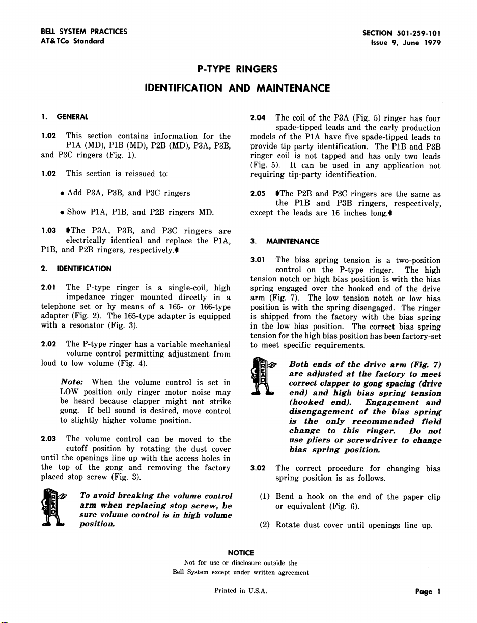
1. GENERAL 2.04 The coil of the P3A (Fig. 5) ringer has four
1.02 This section contains information for the models of the P1A have five spade-tipped leads to
P1A (MD), P1B (MD), P2B (MD), P3A, P3B, provide tip party identification. The P1B and P3B
and P3C ringers (Fig. 1). ringer coil is not tapped and has only two leads
1.02 This section is reissued to: requiring tip-party identification.
. Add P3A, P3B, and P3C ringers 2.05 SThe P2B and P3C ringers are the same as
. Show P1A, P1B, and P2B ringers MD. except the leads are 16 inches long.i
1.03 SThe P3A, P3B, and P3C ringers are
electrically identical and replace the P1A, 3. MAINTENANCE
P1B, and P2B ringers, respectively.0
2. IDENTIFICATION control on the P-type ringer. The high
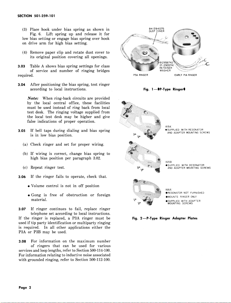
2.01 The P-type ringer is a single-coil, high spring engaged over the hooked end of the drive
impedance ringer mounted directly in a arm (Fig. 7). The low tension notch or low bias
telephone set or by means of a 165- or 166-type position is with the spring disengaged. The ringer
adapter (Fig. 2). The 165-type adapter is equipped is shipped from the factory with the bias spring
with a resonator (Fig. 3). in the low bias position. The correct bias spring
2.02 The P-type ringer has a variable mechanical to meet specific requirements.
volume control permitting adjustment from
loud to low volume (Fig. 4). _ Both ends of the drive arm (Fig. 7)
Note: When the volume control is set in correct clapper to gong spacing (drive
LOW position only ringer motor noise may end) and high bias spring tension
be heard because clapper might not strike (hooked end). EngaKement and
gong. If bell sound is desired, move control disenKaKement of the bias sprinK
to slightly higher volume position, is the only recommended field
2.03 The volume control can be moved to the use pliers or screwdriver to change
cutoff position by rotating the dust cover bias spring position.
until the openings line up with the access holes in
the top of the gong and removing the factory 3.02 The correct procedure for changing bias
placed stop screw (Fig. 3). spring position is as follows.
spade-tipped leads and the early production
(Fig. 5). It can be used in any application not
the P1B and P3B ringers, respectively,
3.01 The bias spring tension is a two-position
tension notch or high bias position is with the bias
tension for the high bias position has been factory-set
are adjusted at the factory to meet
change to this ringer. Do not
arm when replacinK stop screw, be or equivalent (Fig. 6).
sure volume control is in high volume
To avoid breaking the volume control (1) Bend a hook on the end of the paper clip
position. (2) Rotate dust cover until openings line up.
NOTICE
Not for use or disclosure outside the
Bell System except under written agreement
Printed in U.S.A. Page I
SECTION 501-259-101
(3) Place hook under bias spring as shown in 841394o75 _ .....
DUST COVER
Fig. 6. Lift spring up and release it for _ ............ / Si:_ii:_:_:_'_'_::::_:::__,
low bias settingor engage bias spring over hook _ ::_>_ : :_
on drive arm for high bias setting. (_i_ _i_ii_ ::: _
its original position covering all openings. _!!i if? ii:i:_ iNi!ii'::'::i.........
(4) Remove paper clip and rotate dust cover to _'_i!)_})..?_iii::__ _i:i_ :_ !i_i%, ......................._::,:_#;;_
3.03 Table A shows bias spring settings for class %if!i _ iii;i_!_i_:?ii;i:_ii::::_:iii!!::RETAINER(P-29E874):"ii_'___[_/_:::_:_:_:;: ...........',:_
of service and number of ringing bridges _ .... _" WASHER ==========================......
_._4,_:::':::::18I295874
required. P3A RINGER EARLY PIA RINGER
3.04 After positioning the bias spring, test ringer
according to local instructions. Fig. 1--1_P-Type Ringer_l
Note: When ring-back circuits are provided
by the local central office, these facilities _iiiii_i:,i::..........
must be used instead of ring back from local _!_: :i:::
test desk. The ringing voltage supplied from _il..... i i i_!!!iii!i!!!iii_....................
the local test desk may be higher and give ....:::i_ ....{:'i_i_::_,
false indications of proper operation.
3.05 If bell taps during dialing and bias spring .......... 165A:
• SUPPLIED WITH RESONATOR
is in low bias position. _'_ __ ANDADAPTERMOUNTINGSCREWS
(a) Check ringer and set for proper wiring. :_i i!;_:.........
_i_ !:.iiii:_.......
(b) If wiring is correct, change bias spring to .......
i!_:_.
high bias position per paragraph 3.02. i_iii!!_il;i
(c) Repeat ringer test. _p ANDADAPTERMOUNTINGSCREWS
................ i_ii _ii_ _s:
i ,SUPPLIED WITH RESONATOR
3.06 If the ringer fails to operate, check that.
• Gong is free of obstruction or foreign ii:_i_iiiiiiiii::i!i!iii_ii_':ii',:_i;i_!iiiiiii_::_............ IIRESONATORNOTFURNISHED
material. _ ,SUPPLIED WITH ADAPTER
.......: _::_::_i_[iiiiiiiiiiiiiiiiiiiiiiiii!_!!ii_i?___ $MOUN'_SR_NGERONLY
''::::!_ MOUNTING SCREWS
3.07 If ringer continues to fail, replace ringer
telephone set according to local instructions.
If the ringer is replaced, a P3A ringer must be Fig. 2--P-Type Ringer Adapter Plates
used if tip party identification or multiparty ringing
is required. In all other applications either the
P3A or P3B may be used.
3.08 For information on the maximum number
of ringers that can be used for various
services and loop lengths, refer to Section 500-114-100.
For information relating to inductive noise associated
with grounded ringing, refer to Section 500-112-100.
Page 2
 Loading...