

Bell 501-211-102 Service Manual
BELLSYSTEMPRACTICES SECTION501-211 -102
AT&TCo Standard Issue6, May 1982
G6-, G7-, G8-, G13-, G66-, AND K6-TYPE HANDSETS (AMPLIFIER)
IDENTIFICATION, CONNECTIONS, CONVERSION, AND MAINTENANCE
1. GENERAL plastic plate around the volume control assembly in-
1.01 This section contains information for G- and The receiver amplifier board on the last version has
K-type amplifier handsets. Also information three screw terminals. In the G6B last version, the
on D-180413 (modified G8-type) handset is included, yellow conductor in the handset cord is removed. This
These handsets are intended to replace standard G- is a normal condition since the yellow lead is not
or K-type handsets for use by persons with impaired used.
hearing or weak speech and for noisy locations.
1.02 The reasons for reissuing this section are (MD) last version handset except that it is
listed below. Revision arrows are used to em- equipped with a jack to receive the plug-ended H4DU
phasize the more significant changes, handset cord which must be ordered separately.
• Add G13D-104 B. G7-Type (Weak Speech)
• Add G66AM-type handsets internal transistorized transmitter amplifier
• Add K6C handset, potentiometer in the handle controls the level of the
1.03 Table A lists these handsets and their compo- amplifier is located on a printed circuit board at the
nent parts, receiver end of the handle. The polarity guard and
2. IDENTIFICATION ter cavity. The potentiometer assembly, amplifier,
A. G6-Type (Impaired Hearing) transmitter cavity. Internal connections are made by
2.01 The G6-type handset is equipped with an in-
ternal receiver amplifier unit. The volume 2.06 The G7BM handset is identical to the G7B
control potentiometer in the center of the handle ad- (MD) handset except that it is equipped with
justs the loudness setting of the receiver so the hand- a jack to receive the plug-ended H4DU handset cord
set may be used by persons with normal hearing as which must be ordered separately.
well as persons with impaired hearing. C. G8-Type (NoisyLocations)
2.02 The G6B (MD) handset assembly has two 2.07 The GS-type handset is equipped with a tran-
transistorized amplifiers and will operate on sistorized receiver amplifier, a volume control
either polarity. The units are located on a printed cir- potentiometer, and a push-to-listen switch and is in-
cuit board in the receiver cavity. The amplifier, po- tended for use in noisy locations. The volume control
tentiometer assembly, and handset cord connect to a provides up to 10 db of additional receive gain. The
terminal board located in the transmitter cavity, push-to-listen switch, when operated, decreases the
2.03 Three versions of G6B (MD) handsets have ceiver amplifier.
been produced and are referenced as early
(before 1974), later (1974-1977), and last (1977- 2.08 Two versions of G8B (MD) handsets have been
1979). The last version can be identified by a black produced and are referenced as early (before
stead of the chrome metal plate on previous versions.
2.04 The G6BM handset is identical to the G6B
2.05 The G7-type handsets are equipped with an
intended for use by persons with weak speech. The
transmitter output. The transistorized transmitter
one inductor are on a terminal board in the transmit-
and handset cord connect to a terminal board in the
spade-tipped leads.
transmitter output and increases the gain of the re-
Not for use or disclosure outsidethe
Bell System except under written agreement
NOTICE
Printed in U.S.A. Page 1
SECTION501-211-102
1977) and current(since 1977). The vurrentversion position. The center position furnishes 10 dB and the
can be identified by a black plate around the switch extreme position furnishes 20 dB of gain. When the
assembly instead of the chrome metal plate on the slide switch is released a spring returns the switch to
previous version. Also, the receiver amplifier board its normal position.
in the current version has three screw terminals.
2.09 The G8BM handset is identical to the G8B handset cord replaces the G13B handset. The
(MD) handset except it is equipped with a jack G13D handset equipped with a H4EG handset cord
to receive the plug-ended H4DU handset cord which (specify cord on order) replaces the G13A handset.
must be ordered separately. The G13D furnishes normal unamplified receiver
D. D-180413 Handset (Modified G8-Type; Impaired handset is depressed. With either button depressed
Hearing)
2.10 The D-180413 handset is a G8-type handset I_F. G66AM (impaired Hearing)
modified by the service-center. This handset is
intended for use by customers that require more re- 2.16 The G66AM handset is equipped with a receiv-
ceiver gain than is available in the G6-type handset, er-amplifier unit and a polarity guard. The
Both modular and nonmodular versions of the G8- volume control potentiometer in the center of the
type handset can be modified, handle adjusts the loudness setting of the receiver so
2.11 The D-180413 handset is equipped with a re- hearing as well as persons with impaired hearing. It
ceiver amplifier unit. The volume control po- also has a pushbutton which when operated, provides
tentiometer in the center of the handle adjusts the an additional 10 dB gain in the receiver circuit and
loudness setting of the receiver so the handset may 10 dB loss in the transmitter circuit.
be used by persons with normal hearing as well as
persons with impaired hearing. It also has a 2.17 This handsetisintendedforusebycustomers
pushbutton, which when operated, provides an addi- who require more receiver gain than is avail-
tiona115 dB gain in the receiver circuit and 10 dB loss able in the G6-type handset.
in the transmitter circuit. 2.18 It is equipped with a jack to receive the plug-
$Note: The D-180413 handset is replaced by dered separately.
the G66 handset, paragraph 2.06.41
2.12 Connect the D-180413 handset in the same of the D-180413 handset.41
manner as the modular or nonmodular G8-
type handset. SG. K6A or K6C (Impaired Hearing)
2.15 The G13D handset equipped with a H4EH
output until at least one of the two buttons on the
the amplifier furnishes 10 dB of gain and with both
buttons depressed 20 dB of gain.
the handset may be used by persons with normal
ended H4DU handset cord which must be or-
2.19 The G66AM is recommended for use in place
E. G13-Type (impaired Hearing) 2.20 The K6A is a repairable modular handset
2.13 The G13-type handset is equipped with an handset. It is available in the colors listed in Table B.
armored cord and a receiver amplifier unit. 2.21 The K6A has a screw located in the hanger
The volume control switch in the center of the handle indentation under the receiver which holds
controls the loudness setting of the receiver so the the handset shell to the chassis and deck assembly.
handset may be used by persons with normal hearing Inside the handset is an inner chassis which holds the
as well as persons with impaired hearing. Coin tele- handset cord jack assembly, receiver, and transmit-
phones are not assembled or coded with these ter. The amplifier printed circuit board is clipped to
handsets. The handset must be ordered separately the inner chassis. The circuit board contains a col-
and connected per Table C. ume control potentiometer and a transistorized am-
2.14 The G13A (MD) and G13B (MD) handsets fur-
nish normal unamplified receiver output until 2.22 This handset has a U-type receiver which is
the slide switch is moved to the center or extreme compatible with hearing aid pickups.
Page 2
which replaces the K1A (MD) nonrepairable
plifier.
ISS6, SECTION501-211-102
2.23 The K6C is the same as the K6A, except it has so that the yellow lead is electrically wired to the
a Bell System logo and is available only in R terminal on the network and the green lead is
ivory (-50) color, wired to the GN terminal on the network.
2.24 For additional information, refer to Section (3) Test the handset through the full range of vol-
501-210-105.1l ume control.
H. D-180838 Kit of Parts(4-Wire Operation) 3.02 When connecting G6- and G8-type
2.25 This kit of parts contains a terminal board equipped with TOUCH-TONE ®dialing, the dial must
(new) and a MlW strap (G), 616WG jack, and provide common switch contact arrangements which
two screws which are used to convert the G6B (cur- will prevent dial sidetone amplification by the hand-
rent), G6BM, G8B (current), and G8BM handsets set amplifier. If the set contains a 25A3 (MD), 25B3
from two-to four-wire operation per Table D. These (MD), or 25H4 (MD) dial, install a 25W3, 25Y3, or
handsets can be identified by a black plastic plate 25P4 dial, respectively. If these dials are not available
around the volume control assembly instead of the replace set.
chrome metal plate on earlier models and the three
screw terminals on the receiver terminal board. 3.03 The G6BM, G7BM, and G8BM handsets re-
2.26 Remove and discard the old terminal board connected between the handset and the telephone set
(not in all handsets) and modular jack (if a base. The H4DU cord must be ordered separately.
modular handset) in the transmitter end of the hand-
set. Connect the new terminal board and modular 3.04 Schematics: Internal connections of the
jack (if desired) or handset cord per Table E. amplifier type handsets are shown in Fig. 1
I. D-180851 Kit of Parts
2.27 This kit of parts contains modified transmit-
ter and receiver caps, to enable G-type MODULAR-TO-NONMODULAR
handsets to be used with 900-series desk telephone 4.01 Modular G6-, G7-, and G8-type handsets may
sets. The modified handsets cannot be used with 900-
series wall telephone sets. with spade-tipped cords as follows.
J. 226A and 2226A (TRIMLINE®Telephone Sets)Hand (1) Remove the transmitter cap, transmitter unit,
TelephoneSets and transmitter board assembly.
2,28 These hand telephone sets provide up to 20 dB (2) Remove the jack from the transmitter cup.
of receive gain for customers with impaired
hearing. For additional information refer to Section (3) Install a H4CJ cord in accordance with 5.05.
502-303-102.
3. CONNECTIONS ter unit and cup.
3.01 Perform the following to connect amplifier- (5) Connect the handset leads in accordance with
type handsets equipped with spade-tipped Part 3.
cords to rotary dial equipped telephone sets.
(1) Connect red and black leads to the terminals be used on consoles equipped with headset
from which the red and black leads of the re- jacks by using a 478A adapter. This device plugs into
placed handset were removed, the console jack and converts it to a modular jack.
(2) Connect yellow and green leads to the termi- resistor to compensate for the use of a carbon trans-
nals from which the white leads were removed mitter.
(nonmodular) handsets to telephone sets
quire a plug-ended H4DU handset cord to be
through 10.
4. HANDSETCONVERSION
be used on nonmodular telephones equipped
(4) Reassemble the transmitter board transmit-
4.02 Modular G6-, G7-, and G8-type handsets may
The 478A adapter contains the appropriate padding
Page3
SECTION501-211-102
NONMODULAR-TO-MODULAR tarnish on the silver-plated contact
4.03 Nonmodular G6-, G7-, and G8-type handsets attempt should be made to remove it.
manufactured since 1974 may be converted to
modular type in the field. These handsets may be rec- 5.03 SMaintenance of K6-type handsets is limited
ognized by the shape of the handset cord entry hole to replacing the T1 transmitter unit and U5
in the handset handle. Only handles with the rectan- receiver unit._
gular holes may be field modified. These handles are
equipped with a special convertible transmitter cup 5.04 The H4CT handset cord furnished with G6B,
so they can be converted to modular by the addition G7B, and G8B handsets is no longer available.
of a 616W-type jack. Convert the handset as follows. If the original cord requires replacement or if a mod-
(1) Remove the transmitter cup, transmitter unit, nonmodular telephone, modify and install an H4CJ
and transmitter board assembly, cord as follows.
(2) Remove the spade-tipped handset cord leads
from the handset. (1) Tone-out and identify one white conductor.
(3) Install a 616W-type jack (ordered separately) tied in each end of this conductor, designating it
by snapping the jack into the cutout provided green. The other white conductor is designated as
on the transmitter cup. On G6- and G8-type yellow.
handsets the white jack lead is not required and
may be clipped off. (2) Loop and tie or tape the excess length of white
(4) Connect and dress the leads from the 616W- black conductors.
type jack to the transmitter board terminals
as shown in Fig. 3, 4, or 6. (3) Insert conductors in transmitter bowl care-
(5) Reassemble the transmitter board in the board.
handset and replace transmitter cup on hand-
set. (4) Connect to transmitter terminal board as
5. MAINTENANCE shown in Fig. 1, 2, 3, 4, 5, or 6.
ular handset is to be modified for use on a
surfaces is not objectionable and no
For identifying purposes, loose knots may be
conductors to approximate length of red and
fully so as not to disrupt the printed circuit
5.01 Maintenance of G6-, G7-, G8-, modified G8-, 5.05 Radio Frequency Interference: If RFI
and G66-type handsets is limited to the fol- problems, including Citizen Band Radio, are
lowing: encountered the procedures of Section 500-150-100
. Replacing cracked or broken receiver and the telephone set with one modified for radio fre-
transmitter caps quency suppression, the appropriate handset (modi-
e Replacing defective transmitter units same time.
e Replacing defective handset cords 5.06 872AIM and 2872AIM Telephone Sets:
. Cleaning with water-dampened cloth. On some 872A1M and 2872A1M telephone sets
5.02 Maintenance of G13-type handsets is limited white or yellow and green leads from the modular
to cleaning with a water-dampened cloth, as handset jack may have been reversed. If a G6-type
the transmitter and receiver caps are bonded to the handset installed on these sets does not have a re-
handset handle at the time of assembly, ceive output, refer to Section 503-603-101 or 503-603-
compounds on transmitter units, re- 5.07 Modular Telephone Set: When G6BM or
ceiver units, or other component G8BM handsets are connected to some modu-
Do not use cleaning tluids or antirust
parts o[ handset. Discoloration or lar telephone sets, an insufficient receiver gain may
Page 4
should be followed. If it is found necessary to replace
fied for radio suppression) should be ordered at the
(TOUCH-A-MATIC ® telephone sets 32 number), the
102 for handset jack wiring.
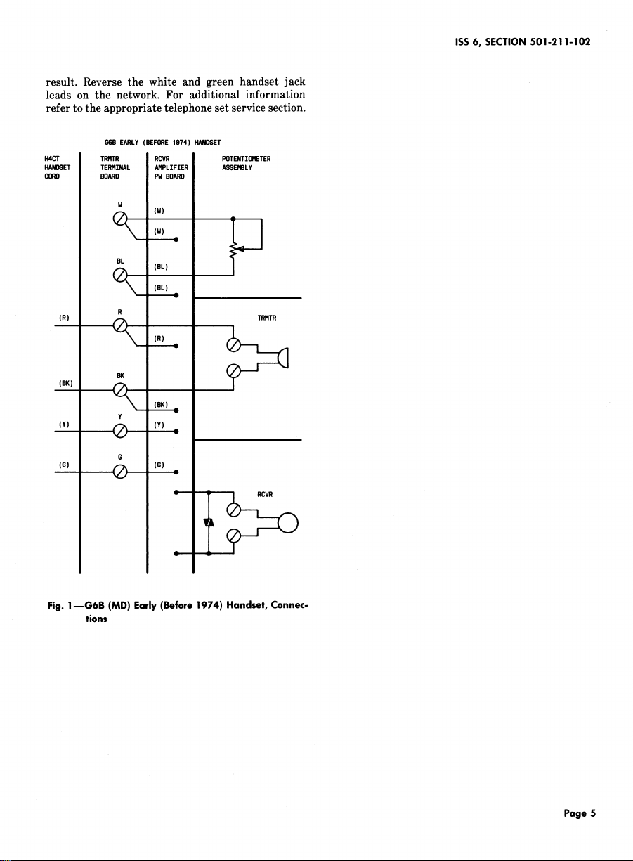
result. Reverse the white and green handset jack
leads on the network. For additional information
refer to the appropriate telephone set service section.
G6BEARLY(BEFORE1974) HANDSET
H4CT TRRTR RCVR POTENTIOFIETER
HANDSET TERRINAL ARPLIFTER ASSERBLY
CORD BOARD PMBOARD
H
(M)
BL (BL) 1
(BL) -
w
a
|
ISS 6, SECTION501-211-102
(R) _ TRRTR(R) -
BK
(BK) %!(')¢
(Y) Q (Y)
G
(G)
' !
w
| (G)
_ I _
Fig. 1--G6B (MD) Early (Before1974) Handset, Connec-
tions
Page5
SECTION 501-211 - 102
H4CT
CUD (G)
GGBLATER(1974-1977) _NDSET
TRMTR I RCVR POTENTI_ETER
TERMI_L m _LIFIER ASSEMBLY
(w)
• (w) _
(R)
(R) __ '
Y RCVR
TRMTR
Page 6
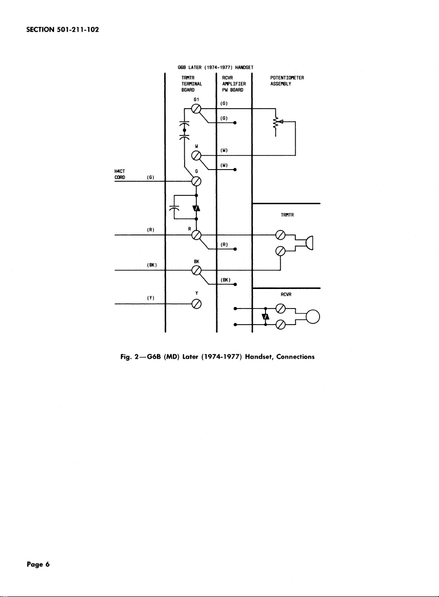
Fig. 2--G6B (MD) Later (1974-1977) Handset, Connections
 Loading...