

Page 1
BELLSYSTEM PRACTICES SECTION 501-136-100
AT&TCo Standard Issue 7, November 1979
STATION TRANSFORMERS
IDENTIFICATION
1 GENERAL unit to be in close proximity to the
1.01 This section contains information on station
transformers. 1.03 Locate transformers where they will be
1.02 This section is reissued to:
. Show KS-20426L3 transformer MD a 110- to 125-volt ac power service outlet.
• Revise Table A. _ Make sure that power service outIet
Danger: When providing power for
illuminated station sets, two or more
transformers should never feed the
same inside wiring pair. If one 1.05 To prevent accidental removal, power cords
transformer is unplugged while the may be fastened to the ac outlet with a
secondary terminals of that transformer power-cord plug-retainer assembly (Section 167-400-210)
are being energized through the inside and plug-in transformers may be secured with a
wiring, by another transformer, the clamp. A clamp is furnished with some of the
exposed terminal blades of the KS-20426L3 (MD) transformers, others have a
unplugged transformer would be molded mounting tab. A retaining clamp is available
energized with 110 to 125 volts ac. for the 85B1 and 95B1 power units. The 2012-type
Installations of multiple transformers transformer may be secured with a 2A clamp.
connected to the same inside wiring
pair should be avoided and corrected
if encountered in the field. 1.06 The B cord clip (size 1) provides a means
Warning: Care should be taken to pulled from the transformer screw terminals.
strip and dress leads connecting to
Io w voltage output terminaIs of
transformers and power unit to assure 1.07 The B cord clips come 10 to a package and
that inadvertent connection to conducting should be ordered as follows:
surfaces or other power source does
not occur. If more than one transformer 1 package (10 clips per package)--Clip, Cord,
or power unit is plugged into a multiple B1-61.
receptacle power strip, there must
be at least one inch separation
between them. Only UL listed 1.08 Remove protective paper from adhesive of
receptacle power strips with adequate B cord clip and stick clip to bottom of station
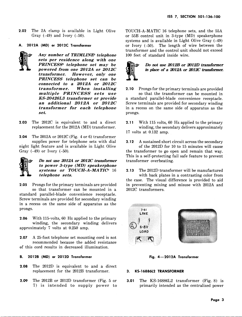
power rating shaH be used. Use of transformers as shown in Fig. 3. Terminate D
a continuous terminal power strip station wire on screw terminals of 2012-type
that allows the secondary output transformer and hook station wire through B cord
terminals of the transformer or power clip as shown in Fig. 3.
ac line source is not recommended.
accessible for inspection and maintenance.
1.04 Transformers discussed in this section require
is not under control of a switch.
of attaching D station wire to station
transformers to prevent the wire being accidentally
Not for use or disclosure outside the
Bell System except under written agreement
NOTICE
Printed in U.S.A. Page 1
Page 2
SECTION 501- 136-100
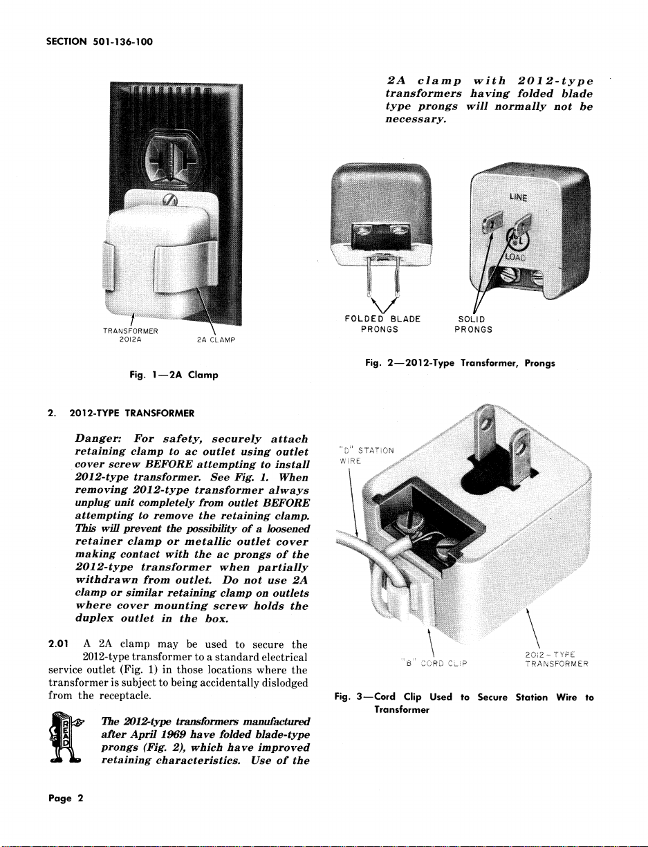
2A clamp with 2012-type
transformers having folded blade
type prongs wiIl normally not be
necessary.
_iiiiii_i_iiiiiiiiiiiiiiii_i_i_i_iii_ii_i_iii_i_i_i_iiii_:i!ii:iiii_ii_ii!iiii_iii_iii_iiiiiiiiiiiiiiiiii_iiiiiiiii_
FOLDED BLADE SOLID
TRANSFORMER PRONGS PRONGS
2012A 2ACLAMP
Fig. 2--2012-Type Transformer, Prongs
Fig. 1--2A Clamp
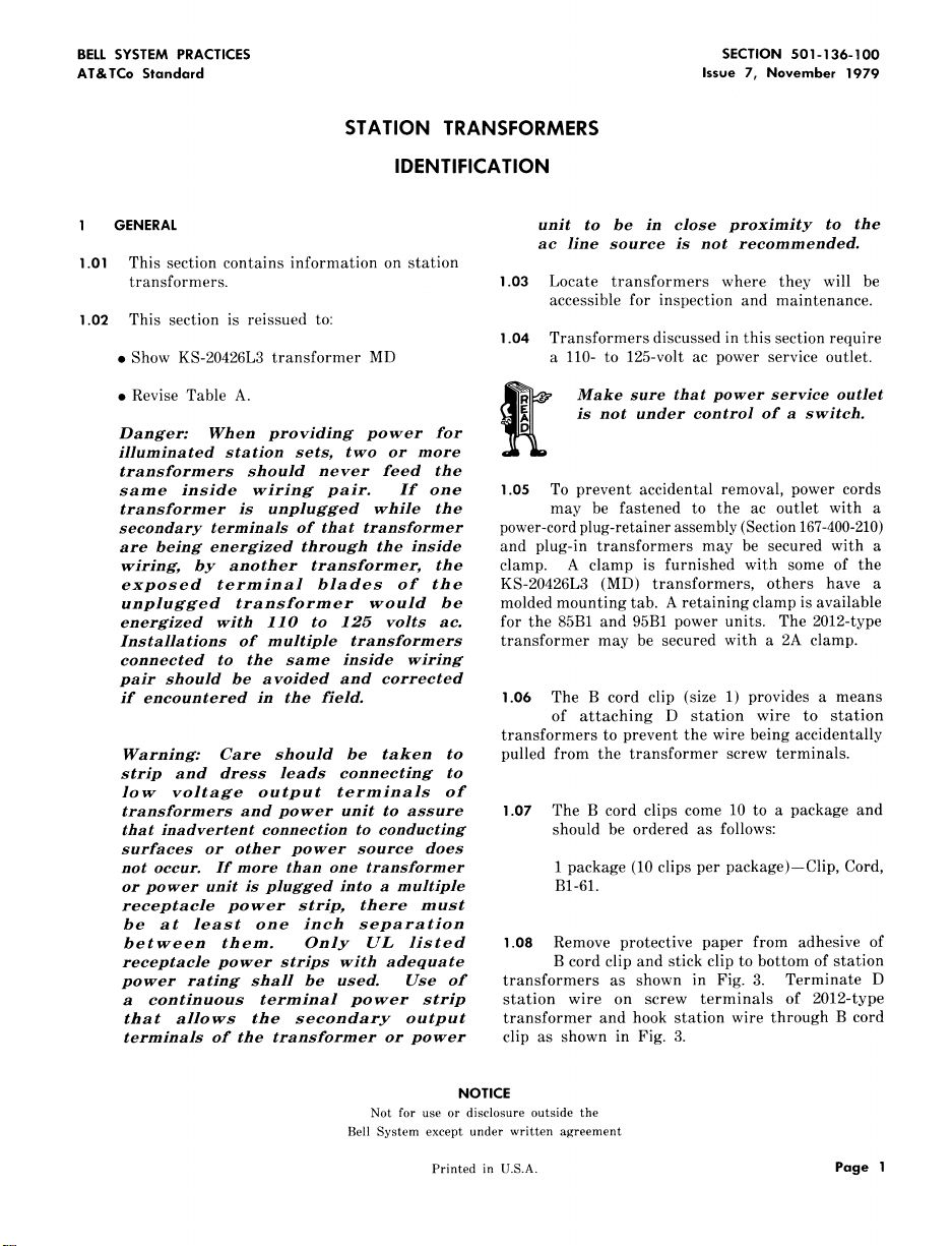
2. 2012-TYPE TRANSFORMER
Danger: For safety, securely attach
retaining clamp to ac outlet using outlet "s_"SZATiON
cover screw BEFORE attempting to install w_R__
2012-type transformer. See Fig. 1. When
removing 2012-type transformer always
unplug unit compIeteIy from outlet BEFORE
attempting to remove the retaining cIamp.
This wilI prevent the possibility of a loosened
retainer clamp or metallic outlet cover .....
making contact with the ac prongs of the
2012-type transformer when partially
withdrawn from outlet. Do not use 2A
clamp or similar retaining clamp on outlets
where cover mounting screw holds the .....
k
duplex outlet in the box. :: \
2.01 A 2A clamp may be used to secure the "\, ............ .... 2o_2-Tv:_:\
2012-type transformer to a standard electrical _'_:' CORDCL_P TRANSFORMER
service outlet (Fig. 1) in those locations where the
transformer is subject to being accidentally dislodged
from the receptacle. Fig. 3--Cord Clip Used to Secure Station Wire to
Transformer
Page 2
after April 1969 have folded blade-type
prongs (Fig. 2), which have improved
The 2012-type transformers manufactured
retaining characteristics. Use of the
Page 3
ISS 7, SECTION 501-136-100
2.02 The 2A clamp is available in Light Olive TOUCH-A-MATIC 16 telephone sets, and the 55A
Gray (-49) and Ivory (-50). or 55B control unit in 3-type (MD) speakerphone
A. 2012A (MD) or 2012C Transformer or Ivory (-50). The length of wire between the
sets per residence along with one
PRINCESS _ telephone set may be __ Do not use 2012B or 2012D transformer
Any number of TRIMLINE _ telephone 100 feet of standard inside wire.
transformer. However, only one
powered from one 2012A or 2012C _ in place of a 2012.4 or 2012C Wansformer.
PRINCESS telephone set can be
connected to a 2012A or 2012C
transformer. When installing 2.10 Prongs for the primary terminals are provided
multiple PRINCESS sets use so that the transformer can be mounted in
KS-20426L3 transformer or provide a standard parallel-blade convenience receptacle.
an additional 2012A or 2012C Screw terminals are provided for secondary winding
transformer for each telephone in a recess on the same side of apparatus as the
set. prongs.
2.03 The 2012C is equivalent to and a direct 2.11 With 115 volts, 60 Hz applied to the primary
replacement for the 2012A (MD) transformer, winding, the secondary delivers approximately
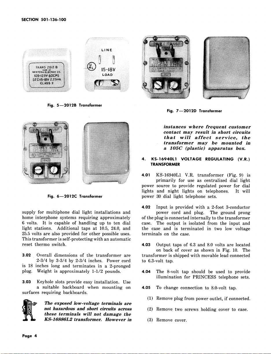
2.04 The 2012A or 2012C (Fig. 4 or 6) transformer
supplies power for telephone sets with dial 2.12 A sustained short circuit across the secondary
night light feature and is available in Light Olive of the 2012D for 10 to 15 minutes will cause
Gray (-49) or Ivory (-50). the transformer to go open and remain that way.
to power 3-type (MD) speakerphone
systems or TO UCH-A-MA TIC _ 16 2.13 The 2012D transformer will be manufactured
Do not use 2012.4 or 2012C transformer transformer overheating.
telephone sets. with back plates in a contrasting color from
2.05 Prongs for the primary terminals are provided in preventing mixing and misuse with 2012A and
so that transformer can be mounted in a 2012C transformers.
standard parallel-blade convenience receptacle.
Screw terminals are provided for secondary winding
in a recess on the same side of apparatus as the
systems and is available in Light Olive Gray (-49)
transformer and the control unit should not exceed
17 volts at 0.132 amp.
This is a self-protecting fail safe feature to prevent
the case. The visual difference is provided to aid
prongs. _: _:,
2.06 With ll5-volts, 60 Hz applied to the primary ii_ii _i_,_,_i_i_i_iii?iiii_ii?F_,_ii_i
winding, the secondary winding delivers _ :_i_
approximately 7 volts at 0.250 amp. _ ii
2.07 A 25-foot telephone set mounting cord is not !ili_
recommended because the added resistance _.... ............................
of this cord results in decreased illumination.
B. 2012B (MD) or 2012D Transformer Fig. 4--2012A Transformer
2.08 The 2012D is equivalent to and a direct
replacement for the 2012B transformer. 3. KS-16886L2 TRANSFORMER
2.09 The 2012B or 2012D transformer (Fig. 5 or 3.01 The KS-16886L2 transformer (Fig. 8) is
7) is intended to supply power to primarily intended as the centralized power
Page 3
Page 4
SECTION 501- 136-100
4:1:::_'?:::J:_I!J::N_i _Ji_i_:
Fig. 5--2012B Transformer
Fig. 6--2012C Transformer power 30 dial light telephone sets.
....... .......
Fig. 7--2012D Transformer
instances where frequent customer
contact may result in short circuits
that will affect service, the
transformer may be mounted in
a 105C (plastic) apparatus box.
4. KS-16940L1 VOLTAGE REGULATING (V.R.)
TRANSFORMER
4.01 KS-16940L1 V.R. transformer (Fig. 9) is
primarily for use as centralized dial light
power source to provide regulated power for dial
lights and night lights on telephones. It will
supply for multiphone dial light installations and power cord and plug. The ground prong
4.02 Input is provided with a 2-foot 3-conductor
home interphone systems requiring approximately of the plug is connected internally to the transformer
6 volts. It is capable of handling up to ten dial case. The output is isolated from the input and
light stations. Additional taps at 10.5, 24.0, and the case and is terminated in two low voltage
25.5 volts are also provided for other possible uses. terminals on the case.
This transformer is self-protecting with an automatic
reset thermo switch. 4.03 Output taps of 6.3 and 8.0 volts are located
onback of cover as shown in Fig. 10. The
3.02 Overall dimensions of the transformer are transformer is shipped with movable lead connected
2-3/4 by 3-3/4 by 2-3/4 inches. Power cord to 6.3-volt tap.
is 18 inches long and terminates in a 2-pronged
plug. Weight is approximately 1-1/2 pounds. 4.04 The 8-volt tap should be used to provide
illumination for PRINCESS telephone sets.
3.03 Keyhole slots provide easy installation. Use
a suitable backboard when mounting on 4.05 To change connection to 8.0-volt tap.
surfaces requiring backboards.
(1) Remove plug from power outlet, if connected.
not hazardous and short circuits across (2) Remove two screws holding cover to case.
these terminals will not damage the
The exposed low-voltage terminals are
KS-16886L2 transformer. However in (3) Remove cover.
Page 4
Page 5

ISS 7, SECTION 501-136-100
IbTABLE A (I
TRANSFORMER APPLICATION (NOTE 1)
TRANSFORMER APPLICATION PARAGRAPH NO.
2012A(MD) For dial light in the TRIMLINE telephone set. For dial-night light 2.03 thru 2.07
or 2012C in the PRINCESS telephone set.
2012B (MD) Power supply for TOUCH-A-MATIC 16 telephone set, and for 55A or 2.08 thru 2.13
or 2012D 55B control unit in 3-type (MD) speakerphone system
KS-16886L2 home interphone systems requiring approximately 6 volts, capable 3.01 thru 3.03
KS-16940L1 For centralized regulated power supply for up to 30 dial and night 4.01 thru 4.07
KS-20426L3 (MD) For centralized power supply mounted in a 2-wire receptacle, will 5.01 thru 5.04
(Note 2) power five dial light telephone sets
2075A Supplies power (15 to 18 volts) for the 41A dial in 660-, 662-, 663-, 8.01 thru 8.03
2186A (MD) Supplies power for the 700A and 700B subscriber sets 9.01 thru 9 06
or 2189A
KS-5714-Type To operate bells, buzzers, and lamps on station systems when the
(MD) circuits are arranged to supply this load separately 10.01 thru 10.03
KS-21239L6 To furnish power for the 24A-type line status indicator 11.01 thru 11.03
85B1 Power unit To furnish ac power for the 4A speakerphone system 12.01 thru 12.03
95B1 Power unit To furnish power for the TOUCH-A-MATIC 32 telephone set 13.01 thru 13.03
Note 1" These transformers are to be used only for the application indicated in this table. Do not substitute one trans-
former for another.
Note 2" Do not use the KS-20426L3(MD) transformer manufactured byAult Inc. Use only theKS-20426L3(MD)
manufactured by other suppliers.
For centralized power supply for multiphone dial light installations and
of handling up to ten dial light stations
lights in telephone sets
and 664-type telephone sets
(4) Change movable lead from 6.3-volt tap to 5. KS-20426L3 (MD) (FIG. 12) TRANSFORMER
8.0-v01t tap.
4.06 Overall dimensions of the transformer are transformers manufactured by A ULT,
7-5/8 by 2-15/16 by 3-5/8 inches. The weight INC., are being recovered from the
is approximately 5-1/2 pounds, field. The transformers should be
4.07 Four 1/4-inch holes are provided on the case premises visit (installation, repair
for mounting. Use a suitable backboard modular conversion activity, etc.) and
for mounting on surfaces requiring backboards, returned without delay to the local
cord into a parallel-blade ac outlet SHOULD NOT be unplugged and then
which does not have a grounded plugged back into the associated ac
An adapter is needed to plug power (MD) (AULT) transformer, the unit
receptable to accommodate a three power outlet, since the stability of
prong plug. The spade-tipped the transformer could be affected by
wire on the adapter should be such action. See Fig. 11 for the
connected to the outlet plate manufacturer's identification marking
screw. Do not cut off the ground on the transformer. This recovery
prong on plug. plan does not apply to A ULT, INC.,
Danger: All KS-20426L3 (MD)
located and recovered on any customer
Western Electric Service Center. When
removing and replacing the KS-20426L3
Page 5
Page 6

SECTION 501- 136-100
Fig. 8--KS-16886L2 Transformer
Yi_:ii_,!!_i!iiiiFiiiiiJiiiiiii iiiiiiiiiiiiiiiiiiiiiiiiiiiiiiiiiiiiiiii!iiiiii_,iiiiiiii,_iKS-20426L1 (MD) transformer or the
manufactured by other suppliers.
ii_ii!iiiit 5.01 The KS-20426L3 transformer (Fig. 12) (not
_ for use in light systems and is mounted in a 2-wire
__ receptacle, power light telephone
_ sets.
manufactureditwill by AULT,fivedialINC') is intended
1 L_
CASE 2 5-6 25.5V J25A
CASE $ L 3---6 .IA
B_'._O_;N_i_N & C_. ! "":-.............
OUTPUT 6.3 v
Fig. 10 Movable Lead Connected to 8-Volt Tap,
KS-16940L1 V.R. Transformer With Cover
Open
i;::i 5.02 The transformer is self-protecting with an
automatic thermo switch and is provided
with primary terminals in the form of parallel
.................. hold the transformer securely in the receptacle.
i blades which serve as the mounting device. If
- "" Danger: For safety, securely attach
__ furnished, the clamp (Fig. 13) must be used to
retaining eIamp to ac outlet using
outlet cover screw BEFORE attempting
Fig. 9--KS-16940L1 V.R. Transformer to install transformer. See Fig. 13.
When removing transformer, always
unplug the power unit completely from
the outlet BEFORE attempting to
Page 6
Page 7

ISS 7, SECTION 501-136-100
KS-20426 L3 TRNSF _ I
_DE BY AULT, INC.
FOR WESTERNELECTRIC _1(_
105-129V 60Hz
SEC: 5.78-7.3V
5.5VA CLASS 2
j l SEC:S76-_.Sv
Fig. 11 KS-20426L3 (MD) Transformer Manufactured
5.03 Some transformers are provided with a
transformer securely in the receptacle by using
the outlet cover screw. See Fig. 14.
by AULT, INC.
Fig. 12--KS-20426L3 (MD) TransformerNot Manufactured
remove the retaining clamp. This by AULT, INC.
will prevent the possibility of a loosened
retainer clamp or metallic outIet cover
making contact with the ac prongs
of the transformer when partiaIly
withdrawn from outlet. Do not use
transformer retaining cIamps on outlets
where the cover mounting screw holds
the duplex outlet in the box.
mounting tab which is used to hold the
t_a
F TRNSF20426
J WADEBY.......
J FORIESTERNELECTRIC
/ 105-129V 60 HZ
L,, S.SVACLASS2
"I@
J
J
Danger: Do not use a KS-20426L3
(MD) transformer equipped with a
mounting tab if ac outlet has a metal
cover or if center cover mounting
screw hoIds the duplex outlet in the
box.
5.04 Recessed screw-type secondary terminals are Fig. 13--Clamp for Mounting Early Version KS-20426L3
provided on the same side of the apparatus (MD) Transformer Not Equipped With Molded
as the primary terminals. With 115 volts, 60 Hz Mounting Tab
applied to the primary winding, the secondary
winding delivers approximately 6.38 volts at 750
milliamperes.
Page 7
Page 8

SECTION 501- 136-100
Fig. 14--KS-20426 Type (MD) Transformer Equipped With Molded Mounting Tab
6. LENGTHS OF FEEDERPAIRS Illumination should be to the customer's satisfaction.
6.01 Table B is to be used as a guide only. After 7. MULTIPLEINSTALLATIONS
the installation of equipment is made, if
illumination is reported as inadequate, then it must Caution: Do not exceed the rated
be assumed that the lengths of feeder pairs have Iamp Ioad of the transformer being
been exceeded, or too many stations have been installed (see Table B).
off-hook at one time. To remedy this situation do
one of the following: 7.01 When a transformer is installed to illuminate
• Double up on the transformer feeder pairs be used to multiple the transformer feeder pairs.
• Split the lamp load by adding a second depends upon the number of lamps to be illuminated
transformer, and their location relative to that of the transformer.
Danger: When providing power for 8. 2075A TRANSFORMER
illuminated station sets, two or more
transformers shouId never feed the 8.01 The 2075A transformer (Fig. 15) supplies
same inside wiring pair. Installations power (15 to 18 volts) for the 41A dial in
of multipIe transformers connected to the 660-, 662-, 663-, and 664-type telephone sets.
the same inside wiring pair should
be avoided and corrected if encountered 8.02 The transformer is equipped with an 18-inch
in the field, power cord terminated in a 2-pronged plug.
Page 8
more than one lamp, connecting blocks may
The number and type of connecting blocks required
Page 9

ISS 7, SECTION 501-136-100
STABLE BQ This plug fits a standard parallel-blade convenience
DIAL LIGHT
receptacle.
TRANSFORMER LIMITATION 8.03 Keyhole slots are provided at the rear of
the transformer for each installation. Use
TRANSFORMERS MAXIMUMNUMBEROF a suitable backboard when mounting on surfaces
(NOTE 1) DIAL LIGHT TEL SETS requiring backboards.
2012A or 2012C
See Note 2 9. 2186A (MD) OR 2189A TRANSFORMER
and Part 2 9.01 The 2189A is a recommended replacement
for the 2186A (MD) transformer.
KS-20426L3 (MD) 5
9.02 These transformers (Fig. 16 and 17) supply
KS-16886L2* 10 power for the 700A and 700B subscriber
. . sets.
KS-16940Ll* 30
Note 1: Do not use common feeder where
more than two sets may be dialed at the
same time. Home runs from each set to
the transformer provide best illumination. ::_::
Illumination should be to customers _:_i:
satisfaction. _,_## i!:
_s __ ,,_c_, ::::_::_ii'
:,_iij
Note 2: Any number of incandescent :_¢_'_: :i:;:_:iii!
TRIMLINE telephone sets per residence i:_:_....___,_._: ::i_iii
along with one PRINCESS telephone set _ _:_,_:z : :_:ii!
may be powered from one 2012A or 2012C c_ .......
transformer. However, no more than one S ;_'_:_!_'/_'_S::: .....J ,,J:_S:_:::
PRINCESS telephone set can be connected .:_:::/ ...........
v .... _ _.:_:..
to a 2012A or 2012C transformer. ..........
*Not recommended for single telephone
: ....... .::(f'::
installations. ...... _ ii !i!!!!!i !ii!!i i!I!ii!
.... i
N
"_ 9.03 These transformers are protected by an
................:_ restores automatically. They are equipped with a
connected to the primary winding. The secondary
Fig. 15--2075A Transformer winding is terminated in screw terminals on the
Fig. 16--2186A (MD) Transformer
internal thermal overload safety switch which
12-inch (2186A) or ll-inch (2189A) power cord
rear of the transformer.
Page 9
Page 10

SECTION 501-136-1O0
_JiiJ_iiiiiiiiiii_iiiii_iiiiiiiiiiiiiii_iiiiiiiiiiii_iiiii!iiiiiiiiiiiiiy_iiiiiiJijJJi!ii!iJi_i_!_iii_
_g2¢2
Fig. 17--2189A Transformer
9.04 With 117 volts, 60 Hz applied to the primary
winding, the secondary delivers approximately
20 volts at 0.345 amp.
9.05 Keyhole slots are provided at the rear of
the transformer for mounting purposes.
Use the backboard furnished with the transformer
on surfaces requiring backboards.
9.06 Attach backboard with appropriate fastening
device depending on the type of mounting
surface.
10. KS-5714 TYPE (MD) TRANSFORMER
10.01 The KS-5714 type transformer is used
primarily to operate bells, buzzers, and
lamps on station systems when the circuits are
arranged to supply this load separately. It is
furnished in a metal box with a removable cover.
The box is approximately 8-3/4 inches long, 4-3/8
inches high, and 4 inches deep, and is arranged SCREWTERMINALS
for wall mounting. This transformer is self-protecting FOR POWER OUTPUT
and has no fuses.
10.02 The KS-5714L4 transformer supplies 15-volts
at 2.2 amps.
10.03 The KS-5714L5transformersupplies15-volts screw-type secondary terminals are provided on
at 1.1 amps. the same side of the transformer as the primary
11. KS-21239L6 TRANSFORMER
11.01 The KS-21239L6 transformer (Fig. 18) is mounting tab which is used to hold the
used to furnish power for the 24A-type line transformer securely in the receptacle by using
status indicator, the outlet cover screw.
11.02 The transformer is self-protecting with an Danger: Do not use a KS-21239L6
automatic thermo switch and is provided transformer equipped with a mounting
with primary terminals in the form of parallel tab if ac outlet has a metal cover
Page 10
blades which serve as the mounting means. Recessed
terminals. Refer to Fig. 18 for electrical specifications.
11.03 Some transformers are provided with a
Fig. 18--KS-21239L6 Transformer
Page 11

ISS 7, SECTION 501-136-100
or if center cover mounting screw the 85B1 power unit where additional mounting
holds the duplex outlet in the box. strength is needed, see Fig. 20.
12. 85B1 POWER UNIT (FIG. 19)
Warning: Care should be taken to
trim and dress Ieads connecting to i
low voltage output of 85B1 power I
unit to assure that inadvertent I
connections to conducting surfaces or i!
other power source does not occur.
Warning: If more than one 85B1 i
andor 95B1 power unit is plugged i
into a multiple receptacle power strip
there must be at least one inch !
separation between the power units. _
Be sure the receptacle power strip
is UL Iisted and rated sufficiently
for the number of power units plugged
in. Use of a continuous terminal
power strip that allows the secondary
output terminals of the transformer
to be in close proximity to the ac line
source is not recommended.
12.01 The 85B1 power unit is used to furnish ac
power for the 4A speakerphone system. Fig. 20m841050818 Retaining Clamp Mounted on
Available in Light Olive Gray (-49) only. AC Outlet Box Using Outlet Cover Mounting
"" Ii
Screw
_ i!!i!!iii!_iiiiiiiii##_i_,!ii. _ 12.03 With a line voltage of 105 to 129 volts,
_!iiii_ii_iii_iii!i_!iiiii!i}i!i!_ii_iiiiii_!!iii_i_ii_!!iiii_!i_i_iii_/_ii_ii_!_i_i_i_ii_ii i_: of 17.5 volts minimum with a current load of 0.200
!i ii!iiiiiiiliil ili!i i t_f'75 :i_:i ampere. When used to power a system one 85B1power unit is required with each 4A speakerphone.
i! 60 Ha, the power unit provides an ac output
Fig. 19--85B1 Power Unit 21. When removing 85B1 power unit,
12.02 The ac input to the unit is by means of to remove the retaining clamp. This
two parallel blades for use in a standard will prevent the possibility of a loosened
two wire receptacle which serves as the mounting retainer clamp or metallic outlet cover
device. The ac output is available through screw making contact with the ac prongs
terminals recessed in the plastic case. A retaining of the 85B1 power unit when partially
clamp (841050818) can be obtained for use with withdrawn from outlet. Do not use
Danger: For safety, securely attach
retaining clamp to ac outlet using
outlet cover screw BEFORE attempting
to install 85B1 power unit. See Fig.
always unplug the power unit completely
from the outlet BEFORE attempting
Page 11
Page 12

SECTION 501- 136-100
in 841050818 or similar retaining 13.03 With a line voltage of 105 to 129 volts,
elamps on outlets where the cover 60 Hz, the power unit provides an ac output
mounting screw holds the duplex outlet of 13.0 volts minimum with a current load of 0.250
in the box. ampere. When used to power the TOUCH-A-MATIC
13. 95B1 POWER UNIT (FIG. 21) unit is required with each TOUCH-A-MATIC 32
Warning: Care should be taken to
trim and dress leads connecting to
low voltage output of 95B1 power Danger: For safety, securely attach
unit to assure that inadverent retaining e/amp to ac outlet using
connections to conducting surfaces or outlet cover screw BEFORE attempting
other power source does not oecur, to install 95B1 power unit. See Fig.
Warning: If more than one 95B1 always unplug the power unit eompletely
andor 85B1 power unit is plugged from the outIet BEFORE attempting
into a multiple receptacle power strip to remove the retaining clamp. This
there must be at least one inch will prevent the possibility of a loosened
separation between the power units, retainer clamp or metallic outlet cover
Be sure the receptacle power strip making contact with the ac prongs
is UL listed and rated sufficiently of the 95B1 power unit when partially
for the number of power units plugged withdrawn from outlet. Do not use
in. Use of a continuous terminal in 841050818 or similar retaining
power strip that allows the secondary clamps on outlets where the cover
output terminals of the transformer mounting screw holds the duplex outlet
to be in close proximity to the ac line in the box.
source is not recommended.
32 telephone set power supply one 95B1 power
telephone set.
20. When removing 95B1 power unit,
set. Available in Light Olive Gray (-49) only.
o ower untsusetourniS tee oneaC .....................................................................................................................................................
13.02 The ac input to the unit is by means of i
two parallel blades for use in a standard
two wire receptacle which serves as the mounting
device. The ac output is available through screw
terminals recessed in the plastic case. A retaining
clamp (84105818) is available for use with the 95B1
power unit where additional mounting strength is Fig. 21--95B1 Power Unit
needed, see Fig. 20.
Page 12
12 Pages
 Loading...