

Page 1
Document Number
121-044-00
Page
1 of 15
Rev. 0
Bell 206L/407 Cargo Hook Kit
Rotorcraft Flight
Manual Supplement
FAA APPROVED
ROTORCRAFT FLIGHT MANUAL
SUPPLEMENT
Bell Helicopter Models
206L, 206L-1, 206L-3, 206L-4, 407
R/N ______________ S/N _______________
Page 2
Document Number
121-044-00
Page
2 of 15
Rev. 0
Bell 206L/407 Cargo Hook Kit
Rotorcraft Flight
Manual Supplement
FAA Approved
INTRODUCTION
This supplement must be attached to the appropriate Bell FAA
approved Rotorcraft Flight Manual when an Onboard Systems
200-195-00 or 200-196-00 Cargo Hook Suspension Kit is
installed in accordance with Supplemental Type Certificate
(STC) NO. SR00418SE. The information contained herein
supplements or supersedes the basic manual only in those areas
listed herein. For limitations, procedures and performance
information not contained in this supplement, consult the basic
Rotorcraft Flight Manual and Rotorcraft Flight Manual
Supplement – Cargo Hook issued by Bell Helicopter.
The 200-195-00 and 200-196-00 Cargo Hook Suspension Kits
include the cargo hook, suspension beam assembly, and pillow
blocks. The suspension beam assembly supports the cargo
hook and allows it to align itself with a load. The pillow
blocks support each end of the suspension beam assembly and
attach to the rotorcraft’s hard points. In addition the kits
include the external manual release cable and external
electrical harness. These items interface with the fixed cargo
hook provisions on the rotorcraft.
The 200-196-00 kit includes a load weigh system. The load
weigh system consists of a cockpit-mounted indicator, a load
cell above the cargo hook, and the interconnecting wiring
harness.
Page 3
Document Number
121-044-00
Page
3 of 15
Rev. 0
Bell 206L/407 Cargo Hook Kit
Rotorcraft Flight
Manual Supplement
FAA Approved
1. LIMITATIONS
1-3. Types of Operation
The basic Rotorcraft Flight Manual and Rotorcraft Flight
Manual Supplement – Cargo Hook issued by Bell Helicopter
remain applicable. With a load attached to the cargo hook,
operation shall be conducted in accordance with the respective
national operational requirements. For US operators FAR Part
133 is applicable. This cargo hook is approved for non-human
cargo, class B and C rotorcraft load combinations only.
The load weigh indicator (included with kit P/N 200-196-00)
shall be operated in accordance with Section 4 of Owner’s
Manual 120-055-00.
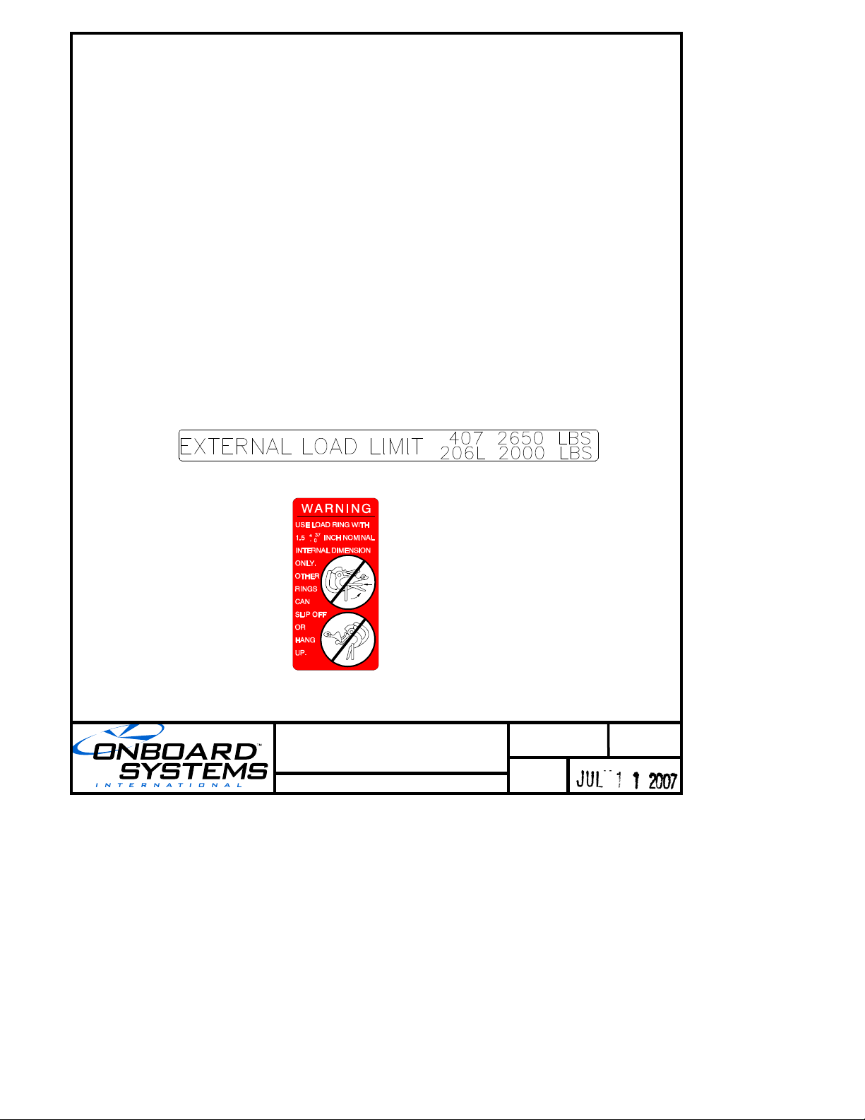
1-20 Placards
When an Onboard Systems kit P/N 200-195-00 or 200-196-00
is installed the following placards apply.
Mounted on suspension beam assembly:
Mounted on the bottom of the cargo hook:
Page 4

Document Number
121-044-00
Page
4 of 15
Rev. 0
Bell 206L/407 Cargo Hook Kit
Rotorcraft Flight
Manual Supplement
FAA Approved
TURN THE WEIGHING SYSTEM OFF WHEN
NAVIGATION EQUIPMENT IS IN USE. NO AIRCRAFT
OPERATION SHOULD BE PREDICATED ON THE
READING OF THE ONBOARD WEIGHING SYSTEM.
ELECTRONIC WEIGHING SYSTEM
1-20 Placards continued
When an Onboard Systems kit P/N 200-196-00 is installed the
following placards apply.
Mounted adjacent to the Onboard Systems load weigh indicator
in full view of pilot or co-pilot:
Mounted adjacent to the power switch and the circuit breaker
in full view of the pilot and co-pilot.
2. NORMAL PROCEDURES
2-3 Pre-flight Check
Consult the Rotorcraft Flight Manual Supplement – Cargo
Hook issued by Bell Helicopters for additional procedures.
Before each Cargo Hook use perform the following
procedures. If the procedures are not successful do not use the
equipment until the problem has been corrected.
1. Inspect all cargo hook fasteners to ensure that they are
tight.
2. Visually inspect the electrical connector for damage and
security.
3. Operate the cargo hook keeper manually and check that it
snaps back to its normal position on the load beam.
Page 5

Document Number
121-044-00
Page
5 of 15
Rev. 0
Bell 206L/407 Cargo Hook Kit
Rotorcraft Flight
Manual Supplement
FAA Approved
2. NORMAL PROCEDURES continued
2-3 Pre-flight Check continued
4. Inspect the cargo hook case and covers for cracks and
damage.
5. Inspect the cargo hook load beam for gouges and cracks.
6. Cycle the cargo hook manual release system to ensure
proper operation.
The cargo hook interfaces with the
rotorcraft’s internal manual release system as
supplied by Bell Helicopter. Consult the
Flight Manual Supplement – Cargo Hook for
operation of manual release system.
7. Cycle the cargo hook electrical release system to ensure
proper operation.
The cargo hook interfaces with the rotorcraft’s
internal electrical release system as supplied
by Bell Helicopter. Consult the Flight Manual
Supplement – Cargo Hook for operation of the
electrical release system.
Page 6

Document Number
121-044-00
Page
6 of 15
Rev. 0
Bell 206L/407 Cargo Hook Kit
Rotorcraft Flight
Manual Supplement
FAA Approved
2. NORMAL PROCEDURES continued
2-3 Pre-flight Check continued
8. Move the cargo hook and the suspension system throughout
their full ranges of motion to ensure the manual release cable
and electrical harnesses have enough slack. The cable or
electrical harnesses must not be the stops that prevent the
cargo hook or suspension from moving freely in all directions.
9. Move the cargo hook back and forth on the suspension beam to
ensure that it rolls freely and that there are no obstructions
within the beam.
When an Onboard Systems 200-196-00 Cargo Hook Suspension
System with Load Weigh is installed, perform the following
additional procedure:
1. Zero the load weigh system or tare the weight on the cargo
hook that is not wanted, such as the weight of a cargo net or
long line, by depressing the zero button on the indicator.
Page 7

Document Number
121-044-00
Page
7 of 15
Rev. 0
Bell 206L/407 Cargo Hook Kit
Rotorcraft Flight
Manual Supplement
FAA Approved
2. NORMAL PROCEDURES continued
Cargo Hook Rigging
Extreme care must be exercised in rigging a load to the Cargo
Hook. If the load ring is too big it may work its way around the
end of the load beam and be supported for a time on the keeper
and then fall free. If the load ring is too small it may jam itself
against the load beam during an attempted release.
The following illustrations show recommended rigging
configurations and potential difficulties that must be avoided.
The examples shown on the following pages
are not intended to represent all problem
possibilities. It is the responsibility of the
operator to ensure that the cargo hook will
function properly with the rigging.
Page 8

Document Number
121-044-00
Page
8 of 15
Rev. 0
Bell 206L/407 Cargo Hook Kit
Rotorcraft Flight
Manual Supplement
FAA Approved
Secondary Ring or Shackle
5/8" Max. cross section
Load
Primary Ring
Incorrect Rigging
Incorrect Rigging
Correct Rigging
Multiple Rings
on Load Beam
Multiple Rings
on Primary Ring
1.50"
Primary Ring I.D.
1.87"
2. NORMAL PROCEDURES continued
Figure 1
Page 9

Document Number
121-044-00
Page
9 of 15
Rev. 0
Bell 206L/407 Cargo Hook Kit
Rotorcraft Flight
Manual Supplement
FAA Approved
Load Ring flips over
the Load Beam and
gyrates.
The flip over often occurs
with long line operations
during landings and take offs.
Load Ring moves
inward and bears
against the keeper
The Keeper is forced
to rotate allowing the
Ring to slip off
2. NORMAL PROCEDURES continued
Un-Commanded Release Due to Too Large of a Load Ring
Load rings that are too large will cause an un-commanded
release. The ring will flip over the end of the load beam and
flip the keeper up and then fall free. Only correctly sized
load rings must be used. See example below.
Figure 2
Page 10

Document Number
121-044-00
Page
10 of 15
Rev. 0
Bell 206L/407 Cargo Hook Kit
Rotorcraft Flight
Manual Supplement
FAA Approved
Jammed Ring
Sling Load
Load hang-up due to
multiple rings on
load beam
Sling Load
Jammed Rings
2. NORMAL PROCEDURES, continued
Load Hang-Up due to Too Small of a Load Ring or Multiple Load Rings
Load rings that are too small or multiple load rings will
hang on the load beam when the load is released. Only
correctly sized load rings must be used. See example below.
Figure 3
Page 11

Document Number
121-044-00
Page
11 of 15
Rev. 0
Bell 206L/407 Cargo Hook Kit
Rotorcraft Flight
Manual Supplement
FAA Approved
2. NORMAL PROCEDURES, continued
Un-Commanded Release Due to Nylon Type Straps
Nylon type straps (or similar material) must not be used
directly on the cargo hook load beam as they have a
tendency to creep under the keeper and fall free. If nylon
straps must be used they should first be attached to a
correctly sized primary ring. Only the primary ring should
be in contact with the cargo hook load beam. See example
below.
Figure 4
Page 12

Document Number
121-044-00
Page
12 of 15
Rev. 0
Bell 206L/407 Cargo Hook Kit
Rotorcraft Flight
Manual Supplement
FAA Approved
2. NORMAL PROCEDURES, continued
Un-Commanded Release Due to Cable or Rope Type Straps
Cable or rope type straps must not be used directly on the
cargo hook load beam. Their braided eyes will work around
the end of the load beam and fall free. If cable or rope is
used they should first be attached to a correctly sized
primary ring. Only the primary ring should be in contact
with the cargo hook load beam. See example below.
Figure 5
Page 13

Document Number
121-044-00
Page
13 of 15
Rev. 0
Bell 206L/407 Cargo Hook Kit
Rotorcraft Flight
Manual Supplement
FAA Approved
2. NORMAL PROCEDURES, continued
The suspension system is designed to
accommodate loads through an angle of up to
55° from vertical —both forward and aft.
However, when loads exceed 55°, the travel
stops on the Pillow Blocks prevent the
Suspension Beam from further rotation and
cause bending stresses to be carried by the
Load Cell. Care should be taken to avoid this
flight regime.
The situation is most likely to occur when
flying at high speeds with light loads, which
have large aerodynamic drag, for example - an
empty fire or fertilizer bucket or an empty long
line. Figure 6 illustrates the adverse loading
situation.
Page 14

Document Number
121-044-00
Page
14 of 15
Rev. 0
Bell 206L/407 Cargo Hook Kit
Rotorcraft Flight
Manual Supplement
FAA Approved
2. NORMAL PROCEDURES, continued
Figure 6
Page 15

Document Number
121-044-00
Page
15 of 15
Rev. 0
Bell 206L/407 Cargo Hook Kit
Rotorcraft Flight
Manual Supplement
FAA Approved
3. EMERGENCY PROCEDURES
Consult the Rotorcraft Flight Manual Supplement – Cargo Hook
issued by Bell Helicopter for emergency procedures during
external load operations.
4. PERFORMANCE
The Rotorcraft Flight Manual Supplement – Cargo Hook issued by
Bell Helicopter remains applicable.
When an Onboard Systems 200-196-00 Cargo Hook Suspension
System with Load Weigh is installed the following applies. The
Load Weigh System is designed and installed as a means of
MONITORING the load (weight) suspended from the cargo hook.
Functional and performance characteristics have not been
determined on the basis of the load cell indication or display.
Therefore, this instrument shall NOT be used as a primary
indication of performance and flight operation must NOT be
predicated on its use.
 Loading...