

Bell 206L, 206L-3, 206L-1, 206L-4, 407 Rotorcraft Flight Manual Supplement
Document Number
121-044-00
Page
1 of 15
Rev. 0
Bell 206L/407 Cargo Hook Kit
Rotorcraft Flight
Manual Supplement
FAA APPROVED
ROTORCRAFT FLIGHT MANUAL
SUPPLEMENT
Bell Helicopter Models
206L, 206L-1, 206L-3, 206L-4, 407
R/N ______________ S/N _______________
Document Number
121-044-00
Page
2 of 15
Rev. 0
Bell 206L/407 Cargo Hook Kit
Rotorcraft Flight
Manual Supplement
FAA Approved
INTRODUCTION
This supplement must be attached to the appropriate Bell FAA
approved Rotorcraft Flight Manual when an Onboard Systems
200-195-00 or 200-196-00 Cargo Hook Suspension Kit is
installed in accordance with Supplemental Type Certificate
(STC) NO. SR00418SE. The information contained herein
supplements or supersedes the basic manual only in those areas
listed herein. For limitations, procedures and performance
information not contained in this supplement, consult the basic
Rotorcraft Flight Manual and Rotorcraft Flight Manual
Supplement – Cargo Hook issued by Bell Helicopter.
The 200-195-00 and 200-196-00 Cargo Hook Suspension Kits
include the cargo hook, suspension beam assembly, and pillow
blocks. The suspension beam assembly supports the cargo
hook and allows it to align itself with a load. The pillow
blocks support each end of the suspension beam assembly and
attach to the rotorcraft’s hard points. In addition the kits
include the external manual release cable and external
electrical harness. These items interface with the fixed cargo
hook provisions on the rotorcraft.
The 200-196-00 kit includes a load weigh system. The load
weigh system consists of a cockpit-mounted indicator, a load
cell above the cargo hook, and the interconnecting wiring
harness.
Document Number
121-044-00
Page
3 of 15
Rev. 0
Bell 206L/407 Cargo Hook Kit
Rotorcraft Flight
Manual Supplement
FAA Approved
1. LIMITATIONS
1-3. Types of Operation
The basic Rotorcraft Flight Manual and Rotorcraft Flight
Manual Supplement – Cargo Hook issued by Bell Helicopter
remain applicable. With a load attached to the cargo hook,
operation shall be conducted in accordance with the respective
national operational requirements. For US operators FAR Part
133 is applicable. This cargo hook is approved for non-human
cargo, class B and C rotorcraft load combinations only.
The load weigh indicator (included with kit P/N 200-196-00)
shall be operated in accordance with Section 4 of Owner’s
Manual 120-055-00.
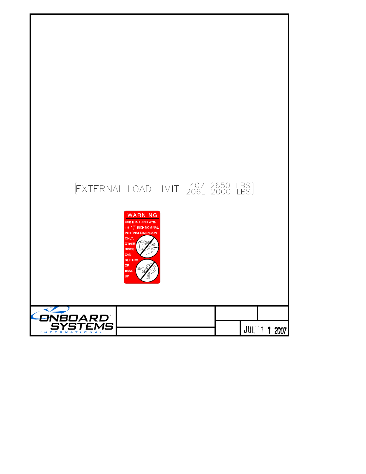
1-20 Placards
When an Onboard Systems kit P/N 200-195-00 or 200-196-00
is installed the following placards apply.
Mounted on suspension beam assembly:
Mounted on the bottom of the cargo hook:

Document Number
121-044-00
Page
4 of 15
Rev. 0
Bell 206L/407 Cargo Hook Kit
Rotorcraft Flight
Manual Supplement
FAA Approved
TURN THE WEIGHING SYSTEM OFF WHEN
NAVIGATION EQUIPMENT IS IN USE. NO AIRCRAFT
OPERATION SHOULD BE PREDICATED ON THE
READING OF THE ONBOARD WEIGHING SYSTEM.
ELECTRONIC WEIGHING SYSTEM
1-20 Placards continued
When an Onboard Systems kit P/N 200-196-00 is installed the
following placards apply.
Mounted adjacent to the Onboard Systems load weigh indicator
in full view of pilot or co-pilot:
Mounted adjacent to the power switch and the circuit breaker
in full view of the pilot and co-pilot.
2. NORMAL PROCEDURES
2-3 Pre-flight Check
Consult the Rotorcraft Flight Manual Supplement – Cargo
Hook issued by Bell Helicopters for additional procedures.
Before each Cargo Hook use perform the following
procedures. If the procedures are not successful do not use the
equipment until the problem has been corrected.
1. Inspect all cargo hook fasteners to ensure that they are
tight.
2. Visually inspect the electrical connector for damage and
security.
3. Operate the cargo hook keeper manually and check that it
snaps back to its normal position on the load beam.

Document Number
121-044-00
Page
5 of 15
Rev. 0
Bell 206L/407 Cargo Hook Kit
Rotorcraft Flight
Manual Supplement
FAA Approved
2. NORMAL PROCEDURES continued
2-3 Pre-flight Check continued
4. Inspect the cargo hook case and covers for cracks and
damage.
5. Inspect the cargo hook load beam for gouges and cracks.
6. Cycle the cargo hook manual release system to ensure
proper operation.
The cargo hook interfaces with the
rotorcraft’s internal manual release system as
supplied by Bell Helicopter. Consult the
Flight Manual Supplement – Cargo Hook for
operation of manual release system.
7. Cycle the cargo hook electrical release system to ensure
proper operation.
The cargo hook interfaces with the rotorcraft’s
internal electrical release system as supplied
by Bell Helicopter. Consult the Flight Manual
Supplement – Cargo Hook for operation of the
electrical release system.
 Loading...