

Page 1

HP NetServer LH 4/LH r
User Guide
Page 2

Notice
The information contained in this document is subject to change without notice.
Hewlett-Packard makes no warranty of any kind with regard to this
material, including, but not limited to, the implied warranties of
merchantability and fitness for a particular purpose. Hewlett-Packard shall not
be liable for errors contained herein or for incidental or consequential damages in
connection with the furnishing, performance, or use of this material.
Hewlett-Packard assumes no responsibility for the use or reliability of its software
on equipment that is not furnished by Hewlett-Packard.
This document contains proprietary information that is protected by copyright. All
rights are reserved. No part of this document may be photocopied, reproduced, or
translated to another language without the prior written consent of HewlettPackard Company.
Windows is a registered trademark of Microsoft in the U.S. and other countries.
CompuServe is a U.S. trademark of CompuServe, Inc. NetWare and Intranetware
are registered trademarks of Novell, Inc. SCO is a trademark of The Santa Cruz
Operation, Inc. Symbios is a registered trademark of LSI Logic Corp.
Hewlett-Packard Company
Network Server Division
Technical Marketing / MS 49EU-FQ
5301 Stevens Creek Boulevard
P.O. Box 58059
Santa Clara, CA 95052-8059 USA
© Copyright 1998, Hewlett-Packard Company.
Audience Assumptions
The user guide is for the person who installs, administers, and troubleshoots
network servers. Hewlett-Packard Company assumes you are qualified in the
servicing of computer equipment and trained in recognizing hazards in products
with hazardous energy levels.
ii
Page 3

Contents
1 Introduction.................................................................................................. 1
Verifying Contents......................................................................................... 1
HP NetServer LH 4 Installati on P r oc edur es............................................... 2
HP NetServer LH 4r Installation Procedures.............................................. 2
HP NetServer LH 4 to LH 4r Conversion K it .............................................. 2
2 Controls, Ports, and Indicators.................................................................... 4
Front Panel .................................................................................................... 4
Rear Panel Controls, Ports, and I ndicators .................................................... 8
Connecting the NetServer to AC Power..................................................... 9
Power-On Tests.......................................................................................10
3 Removing and Replacing Covers.............................................................. 11
Removing the HP NetServer LH 4 Covers................................................... 11
Bezel....................................................................................................... 11
Cover 1................................................................................................... 12
Cover 2................................................................................................... 13
Cover 3................................................................................................... 13
Replacing t he HP NetServer LH 4 Covers................................................... 13
Removing the HP NetServer LH 4r Covers.................................................. 14
Bezel....................................................................................................... 14
Cover 1................................................................................................... 16
Cover 2................................................................................................... 16
Cover 3................................................................................................... 17
Replacing t he HP NetServer LH 4r Covers.................................................. 17
4 Accessory Boards ...................................................................................... 19
The I/O Board.............................................................................................. 19
Installing Accessory Boards......................................................................... 21
5 Installing Additional Memory..................................................................... 25
Installing Addit ional Memory in t he LH 4...................................................... 26
Installing Addit ional Memory in t he LH 4r..................................................... 28
6 Installing Mass Storage Devices................................................................ 33
Supported Mass Storage Devices................................................................ 33
SCSI Addressing..................................................................................... 34
iii
Page 4

Contents
Hot-Swap Mass Storage.......................................................................... 35
Installing a Hot-Swap Hard Disk Drive..................................................... 39
Removing a Hot-Swap Hard Disk Drive................................................... 44
Integrated HP NetRAID............................................................................... 44
7 Installing Additional Power Supplies........................................................ 47
Installing an Addit ional Power Supply .......................................................... 48
Ventilating Fans...........................................................................................48
8 Installing the NetServer in an HP Rack System/E or Rack Syst em/U...... 51
Preparing for Instal lation.............................................................................. 52
Prev ent Rack Ti p- Over , Equipment Damage and Injury .......................... 52
Tools Required........................................................................................ 53
Installing the Slides..................................................................................... 54
Marking the Columns............................................................................... 54
Installing Rack Nuts................................................................................. 55
Installing Bar Nuts................................................................................... 56
Attaching the Slides.................................................................................58
Installing the NetServer............................................................................... 61
Securing the NetServer to the Rack............................................................. 64
9 Connecting the Monitor, Keyboard, Mouse, and UPS.............................. 69
10 Configuring the NetServer ....................................................................... 71
Contents of t he NetServer Navigator CD- ROM............................................ 71
Obtaining NetServer Product History........................................................... 71
Readme Fi le ................................................................................................ 72
Viewing the Readme File......................................................................... 72
Configur ation Assistant and I nstallation Assistant ........................................ 72
Run Configur ation Assistant and I nstallation Assistant............................. 73
Express Configuration ............................................................................. 73
Custom Conf igurati on.............................................................................. 76
Replicat e Configur ation........................................................................... 78
HP Management S olutions.......................................................................... 78
TopTools for Servers............................................................................... 79
Integrated Remote Assistant.................................................................... 80
PcANYWHERE-32.................................................................................. 80
NetServer Utilities................................................................................... 80
User Preferences.....................................................................................81
Setup Utility............................................................................................. 81
iv
Page 5

Contents
Symbi os Configurat ion Utility....................................................................... 83
ISA Non-Pl ug- and- P lay Boards (Opt ional) ................................................... 84
Reserving Resources for ISA Non-Plug-and-Play Boards........................ 84
Configur ing an ISA Non-P lug-and-Play B oar d ......................................... 85
11 HP Informat ion Assistant......................................................................... 89
Using Information Assistant......................................................................... 89
Getting Help............................................................................................ 89
Finding Information ................................................................................. 89
Copying and Pri nting Information ............................................................ 90
Installing HP Information Assistant Software................................................91
Installing from the CD-ROM .................................................................... 91
12 Troubleshooting....................................................................................... 93
Troubleshooti ng Tools................................................................................. 93
DiagTools.................................................................................................... 94
Common Installation Problems.................................................................... 95
Troubleshooti ng S equenc e...................................................................... 96
If t he S y stem Does Not Power On........................................................... 97
If the System Powers On, but Fails POST (Power-On Self Test)............. 98
If t he S y stem Passes POST (Power-On S elf T est) but Does Not Function98
Error Messages........................................................................................... 99
POST Error Codes.................................................................................. 99
Appendix A Installing the NetServer in an HP Systems Rack....................102
Preparing for Instal lation.............................................................................102
Tools Required.......................................................................................103
Installing the Slides....................................................................................104
Marking the Columns..............................................................................104
Installing Rack Nuts................................................................................105
Installing Bar Nuts..................................................................................107
Attaching the Slides................................................................................108
Completing the NetServer Installation ........................................................110
Appendix B Specifications...........................................................................111
Environment...............................................................................................111
Weight and Dimensions..........................................................................112
Appendix C Regulatory Information............................................................113
Notice for USA ...........................................................................................113
v
Page 6

Contents
FCC Radio Frequenc y E missions Stat ements ........................................113
CD-ROM................................................................................................114
Notice for Canada: DOC Requirement s......................................................115
Battery...................................................................................................115
Notice for Fi nland: Laser Saf ety Statement ................................................117
Notice for Germany....................................................................................117
Noise Declaration and Ergonom ics.........................................................117
Laser Safety Statement..........................................................................117
Notice for Japan.........................................................................................118
For Products Label ed as Cl ass B............................................................118
For Products Label ed as Cl ass A............................................................119
Power Line Harmonics............................................................................119
Notice for Korea: RFI Statement.................................................................119
Notice for Taiwan: Class A Warning Statement..........................................120
Mexico: Hardware Warranty Statement......................................................120
Notice for U.K. : General Appr oval ..............................................................122
Appendix D Warranty and Softw are License ..............................................123
Warranty....................................................................................................123
HP Soft ware Produc t License Agreement...................................................123
Appendix E Service and Support ................................................................125
Index..............................................................................................................127
vi
Page 7
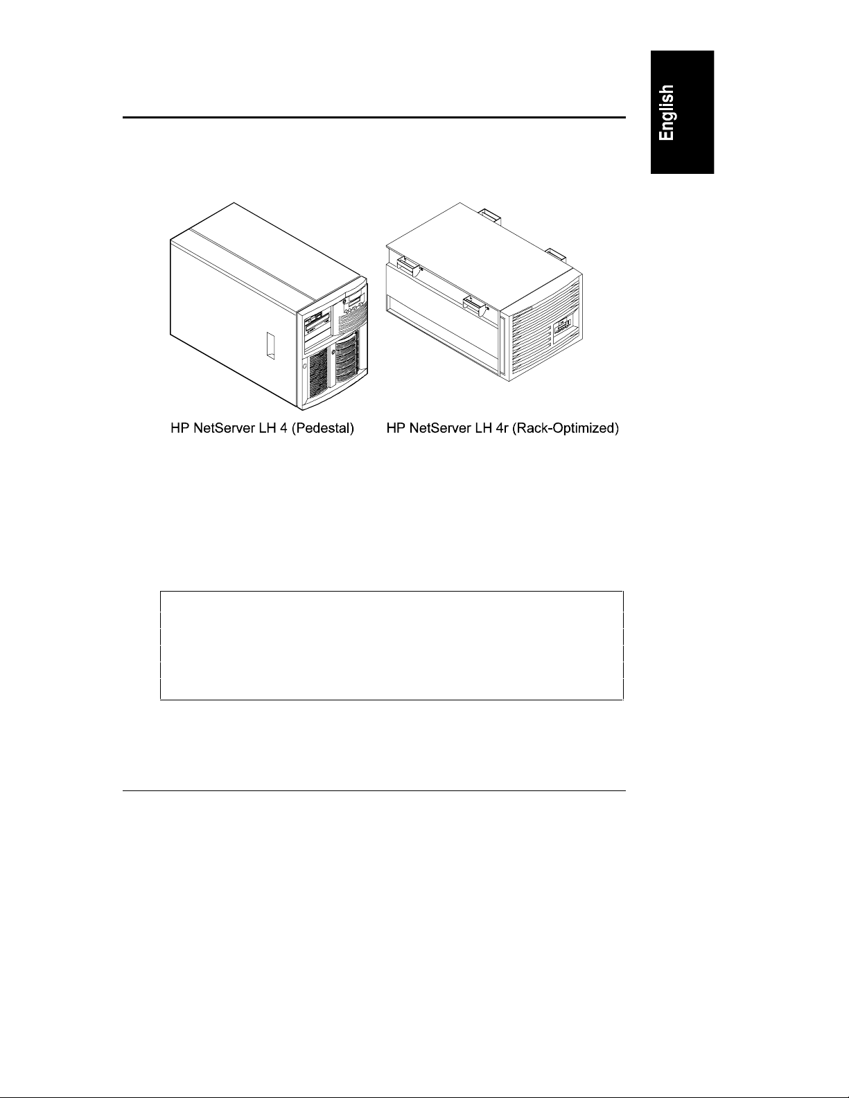
1 Introduction
This User Guide contains information for both the HP NetServer LH 4 (the floorstanding pedestal configuration) and LH 4r (the rack-optimized configuration).
The NetServer configurations are shown below.
Figure 1-1. NetSer ver Conf igurations
Verifying Contents
Unpack and verify the contents of the shipping box against the Contents
Checklist included with your HP NetServer. If anything is missing or damaged,
contact your reseller.
CAUTION The HP NetServer weighs approximately 120 pounds as
shipped. Do not attempt to lift the NetServer by yourself.
Follow local regulations, and use one person for every 40
pounds of NetServer weight when lifting the NetServer.
Failure to observe this warning could result in serious injury,
or damage to the NetServer.
Store the empty boxes and packing material in a safe place. This is especially
important if you plan to ship the NetServer elsewhere for final installation.
1
Page 8

Chapter 1 Introduction
CAUTION It is critical to disassemble and rebox all electronic
components before reshipment. Electronic components
(especially hard disk drives) can sustain damage when
shi p p ed in rack enclosu res.
HP NetServ er LH 4 In stallation Pr ocedures
Refer to the HP NetServer LH 4 Installation Road Map for step-by-step
installation instructions.
If you are installing any accessories, refer to the documentation shipped with the
accessor y pack age.
HP NetServ er LH 4r I nstallation P rocedur es
Refer to the HP NetServer LH 4r Installation Road Map, for step-by-step
installation instructions.
NOTE The HP NetServer LH 4r Installation Road Map does not
include procedures for installing the system in a rack. Refer to
Chapter 8, "Mounting the HP NetServer LH 4r in a Rack," for
detailed rack installation instructions.
If you are installing any accessories, refer to the documentation shipped with the
accessor y pack age.
You should also review:
• All documentation that comes with your rack, such as the Rack
Installation Road Map.
• The Rack Cabling Reference for the HP NetServer LH 4r.
• The user guide for your mass storage units: for example, the HP Rack
Storage/8 System Installation Guide.
HP NetServ er LH 4 to LH 4r Con ver sion Kit
The HP NetServer LH 4 is a stand-alone pedestal model. If you want to install the
LH 4 in a rack, contact your reseller for information about the HP NetServer LH
4 to LH 4r Conversion Kit. This kit contains all components needed to convert
your HP NetServer LH 4 into a rack-optimized HP NetServer LH 4r.
2
Page 9
2 Controls, Ports, and Indicators
You control the HP NetServer with the Front Panel located on the front of the
NetServer. The NetServer communicates to the network and other devices
through the connectors on the rear panel. This section covers these controls and
communication connectors.
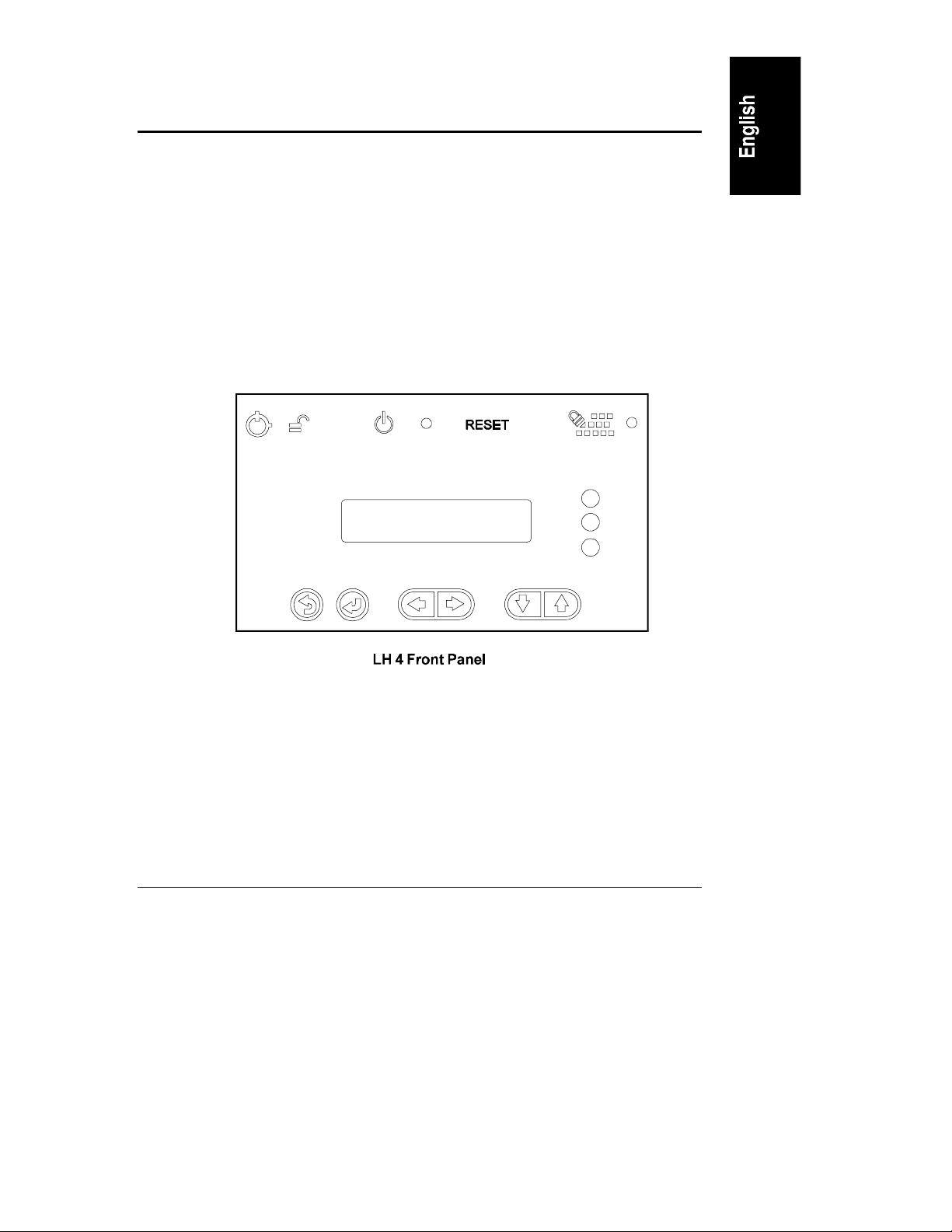
Front Panel
Before installation, familiarize yourself with the HP NetServer’s switches and
indicators. The figure below shows the HP NetServer LH 4’s Front Panel (the HP
NetSer ver LH 4r is similar, but has no lock).
Figure 2-1. HP NetServer LH 4’s Front Panel
3
Page 10

Chapter 2 Controls, Ports, and Indicators
Table 2-1. Front Panel Switch and Indicat or Def initions
Control Descriptio n
Lock (LH 4 only)
DC Power
Switch
and indicat or
light
RESET
Keyboard lock
and indicat or
light
Locks system to prevent unauthorized use.
Turns the NetSer ver on and off. This switch is behind the
protective door on the front panel. Push once to turn on, again to
turn off. (To disconnect the NetServer from AC power, remove
the AC power cord from the power supply cage on the rear.)
Resets the NetServer from internal ROM. This switch is behind
the protective door on the front panel.
Locks system keyboard to prevent unauthorized use.
4
Page 11
Chapter 2 Controls, Ports, and Indicators
Status screen
Reports various types of system status. The buttons below the
screen control these menu functions:
Return to a previous selection.
Select a menu item.
Reserved for future use.
Scroll down or up.
NOTE At the time of this printing, th e Status LEDs were not enabled. If you register
for the Proactive Notification Service, HP will notify you via e-mail when the
next firmwar e version is ready to download and use. (See Appendix E,
"Service and Support," for more details.)
Status LEDs Indicates various types of system status:
Green = Normal operation
Yellow = Abnormal operation
Red = Problem detected
Table 2-2. Front Panel Menu, as Shown on St at us Scr een
System Information
Reports system h ardware details and software version
numbers.
Field Replaceable Unit
Information
Contrast Adjustment
Identifies part and revision number s for components.
Use th e arr ow keys to change the LCD contrast for better
readability.
5
Page 12

Chapter 2 Controls, Ports, and Indicators
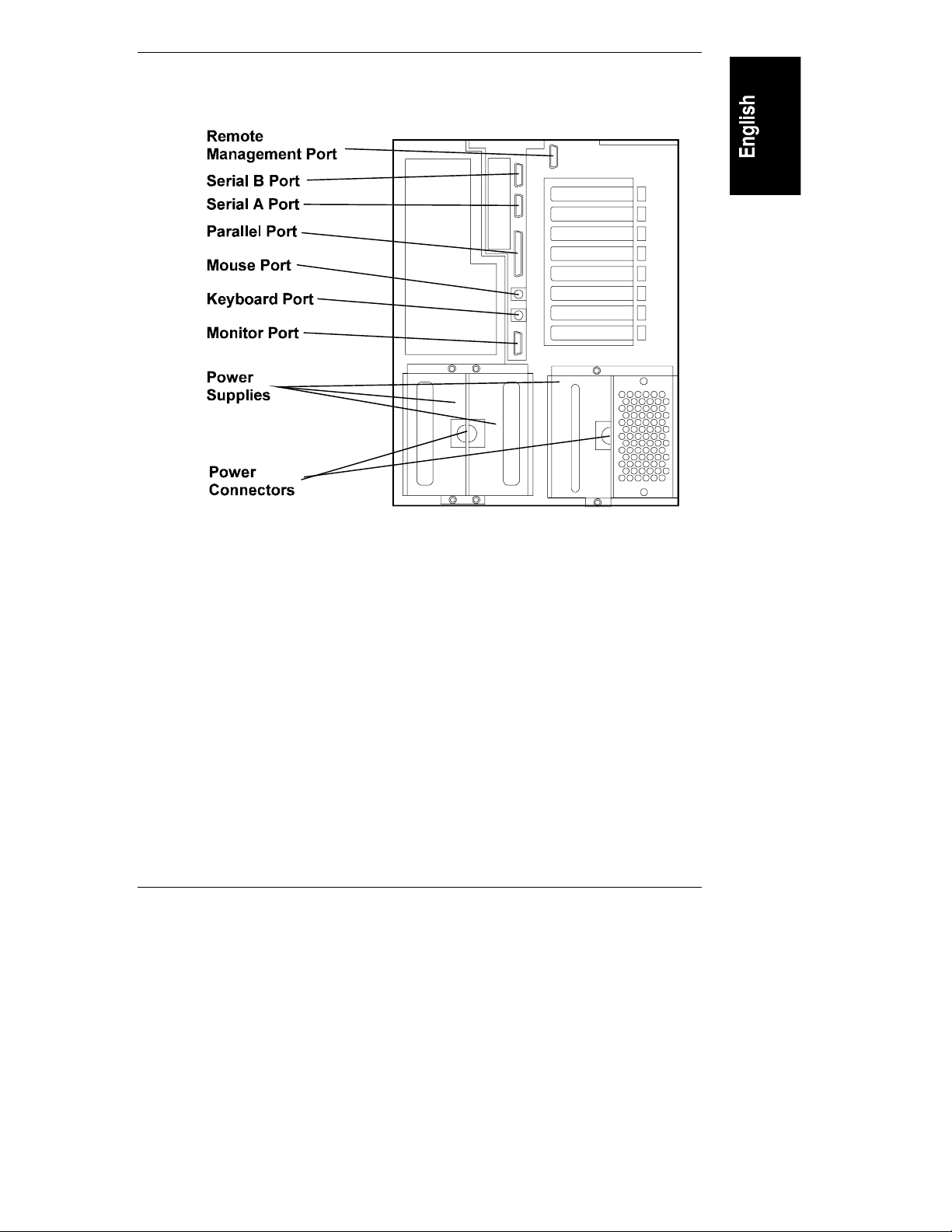
Rear Panel Controls, Ports, and Indicators
Refer to Figure 2-2 below to locate features on the NetServer’s rear panel:
• The Remote Management Port links the NetServer to a console for r eal-
time diagnosis of system operation .
• The Ser ial B Port is a standard serial port.
• The Ser ial A Port is a standard serial por t.
• The Parallel Port is a standard parallel port.
• The Mouse Port accep ts a stan dar d P C mouse.
• The Keyboar d P ort accepts a s tandard PC k eyboar d .
• The Monit or Port accept s a monitor wi th up to 1024 x 768 x 256
resolution, with a 60-75Hz video refresh rate. The NetServer contains
1MB of vi deo RAM.
• The NetServer comes with three 550W power supplies installed: two in
the left rear, and one in the right rear. The optional Redundancy Kit
provides a fourth power supply to install in the right rear. Since the
NetServer only requires three power supplies to run, installing a fourth
power supply prevents service i nterrupt ions from a sin gl e power supply
failure. With the Redundancy Kit installed a power supply can be
hot-swapped.
• The Power C onnector a ccep ts two sta nda rd power cables to connect the
NetSer ver with the site AC power source.
6
Page 13
Chapter 2 Controls, Ports, and Indicators
Figure 2-2. Rear Panel and Port s
Connecting th e NetSer ver to AC Power
When you con nect t he NetS erver to an AC power source, t he server t emporari ly
draws additional current. This occurs even when th e system is in standby mode.
This "inrush current" is much greater than the server’s normal oper atin g n eeds.
Generally, your external AC power source can h an dle the inrush current.
If you install several NetServers on one cir cuit, however, precautions are
necessary. If there is a power failure and power is then restored, all the ser vers
immediately begin to draw inrush current at the same time. If the circuit br eakers
on the incoming power lin e have insufficient capacity, they may trip and thus
prevent the servers from powering u p .
When preparing your site for installation, allow for the additional inrush current.
Follow these circuit breaker recommendation s before installing the server at your
site:
7
Page 14

Chapter 2 Controls, Ports, and Indicators
• In North Amer ican, use a 20-amp-minimum circuit with one NEMA AB1
class 14B breaker for each 16 -amp Power Distribution Un i t ( PDU).
• In Europe:
◊ For a single NetSer ver in a rack, use a 15-amp-minimum circuit with
one IEC MCB C-type breaker for each 16-amp PDU.
◊ For multiple NetServers in a rack, use a 15-amp-minimum circuit with
one IEC MCB D-type breaker for each 16-amp power distribution
unit.
Each 16-amp PDU can accommodate a maximum of two NetServers.
When the proper power supply is available, connect the NetServer to the AC
power source.
Power-On Tests
The NetServer runs a set of diagnostic tests when it is first connected to a power
source. If the NetSer ver passes the tests, you will see:
HP NetServer
LH 4
If the NetServer does not pass the tests, you will see:
<error code>
Display now?
Press Enter to view the error message. Write the error message down and refer to
"POST Codes" in Chapter 12 , "T roubleshooting. "
8
Page 15

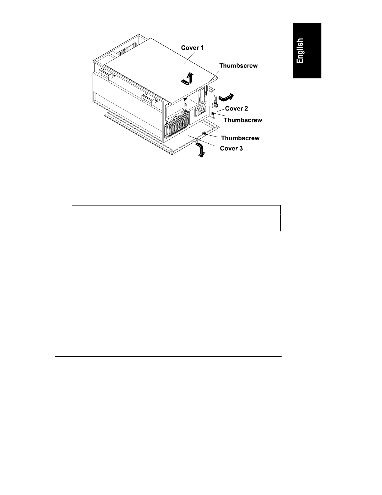
3 Removing and Replacing Covers
The NetServer has three removable cover panels:
• Cover 1 cover s the side where the I/O board is located.
• Cover 2 covers th e area above the system boar d as s e mbly.
• Cover 3 covers the side wher e the p rocessor and memor y cages are
located.
The followin g sections describe removing the covers from the LH 4 and LH 4r.
WARNING Before removing covers, always disconnect the power cords
and unplug t elephone cables. Disconnect the power cords to
avoid exposure to high energy levels that may cause burns
when parts are short-circuited by metal objects, such as tools
or jewelry. Disconnect telephone cables to avoid exposure to
shock hazard from telephone ringing voltages.
Note that the power switch does not turn off the standby
power. Disconnect the power cord to turn off standby power.
If the backlight on the LCD display is on, so is standby
power.
CAUTION Wear a wrist strap and use a static-dissipating work surface
connected to the chassis at all times.
Removing the HP NetServer LH 4 Covers
To remove the covers, first unlock the bezel, using the supplied key, and remove
it from the front of the NetServer .
Bezel
The bezel connects to the front of the NetServer chassis with two snap-in
connectors at the top front of the chassis and two tabs that fit in to two slots on the
9
Page 16
Chapter 3 Removing and Replacing Covers
bottom front of the chassis. To r emove, pull the bezel forward until it unsnaps,
then lift th e bezel forward and upward from the chassis face (see Figure 3-1).
Figure 3-1. Rem oving the HP NetServer LH 4 Bezel
CAUTION The NetServer cover s are heavy. Support them as you remove
them, and allow r oom to move them away from the NetServer
and for storage when removed.
Cover 1
Onc e you ha ve rem ove d the bezel, r e move cover 1 by unscrewi ng th e thum bs c rew
and then pulling the cover forward to disengage it. Lift it outward and away from
the chassis (see Figure 3-2).
Cover 2
Remove cover 2 by unscrewin g th e thumbscrew, pulling the cover forward and
then slightly sideways to disengage it. Lift it up and away from the chassis (see
Figure 3-2).
10
Page 17
Chapter 3 Removing and Replacing Covers
Cover 3
Remove cover 3 by unscrewin g th e thumbscrew an d pulling it forward to
disengage it. Lift it outward and away from the chassis (see Figure 3-2).
Figure 3-2. HP NetServer LH 4 Covers
Replacing the HP NetServer LH 4 Covers
CAUTION Replace all cover s befor e operating this NetServer, even for a
short time. Otherwise, damage to system components may
result due to improper cooling air flow.
Insert the tabs in side the rear of the cover into the slots at the rear of the ch assis
and slide the cover towar d the rear. Tighten the thumbscrew at th e front of the
cover.
Removing the HP NetServer LH 4r Covers
To remove the covers, first remove the bezel from the front of th e NetServer .
11
Page 18
Chapter 3 Removing and Replacing Covers
Bezel
The bezel h as thr ee clips that mount onto a hinge assembly, which is secured to
the NetServer chassis. To remove the bezel, simply pull it towar d you until it
comes free from the NetServer (see Figure 3-3).
Figure 3-3. Rem oving the HP NetServer LH 4r Bezel
CAUTION Do not unscrew th e NetServer from the rack until you have
extended th e anti-tip foot from under the front of the rack.
This anti-tip device must be extended to prevent the rack and
NetSer ver from tipping over, which could damage the
NetServer and injure people.
If it is secured to the rack, unscrew th e NetServer chassis from t he rack, as shown
in Figures 3-4 (front) an d 3-5 (rear).
Do not unscrew th e entire hinge or bracket from the NetSer ver. Remove only the
outer screws so the hinge and the bracket remain attached to the NetServer
chassis.
12
Page 19
Chapter 3 Removing and Replacing Covers
Figure 3-4. Screw and Cover Locat i ons
Remove the two screws that connect the z bracket to the column (see
Figure 3-5).
Two Screws
Fasten
NetServer
to Bracket
Figure 3-5. Rem oving the Z-Bracket to t he NetSer ver
13
Page 20

Chapter 3 Removing and Replacing Covers
After unsecuring brackets, pull the NetServer forward from the rack until the
lockout device engages with a click.
CAUTION The NetServer cover s are heavy. Support them as you remove
them, and allow r oom to move them away from the NetServer
and for storage when removed from the NetServer.
Cover 1
Remove cover 1 by unscrewin g th e thumbscrew an d pulling the cover forward to
disengage it. Lift it up and away from the chassis (see Figure 3-6).
Cover 2
Remove cover 2 by supporti ng it with your hand, then unscrewing th e
thumbscrew and pulling the cover for ward to disengage it. Lift it away from the
chassis (see Figure 3-6).
Cover 3
Remove cover 3 by supporti ng it with your hand, then unscrewing th e
thumbscrew. Pull the cover forward to disengage it and catch it as it falls away
from the chassis (see Figure 3-6).
14
Page 21
Chapter 3 Removing and Replacing Covers
Figure 3-6. HP NetServer LH 4r Covers
Replacing the HP NetServer LH 4r Covers
CAUTION Replace all cover s befor e operating this NetServer, even for a
short time. Otherwise, damage to system components may
result due to improper cooling air flow.
Insert the tabs in side the rear of the cover into the slots at the rear of the ch assis
and slide the cover towar d the rear. Tighten the thumbscrew at th e front of the
cover.
Return the NetServer into the rack. Replace the scr ews removed from the fr ont
and rear.
15
Page 22

Page 23

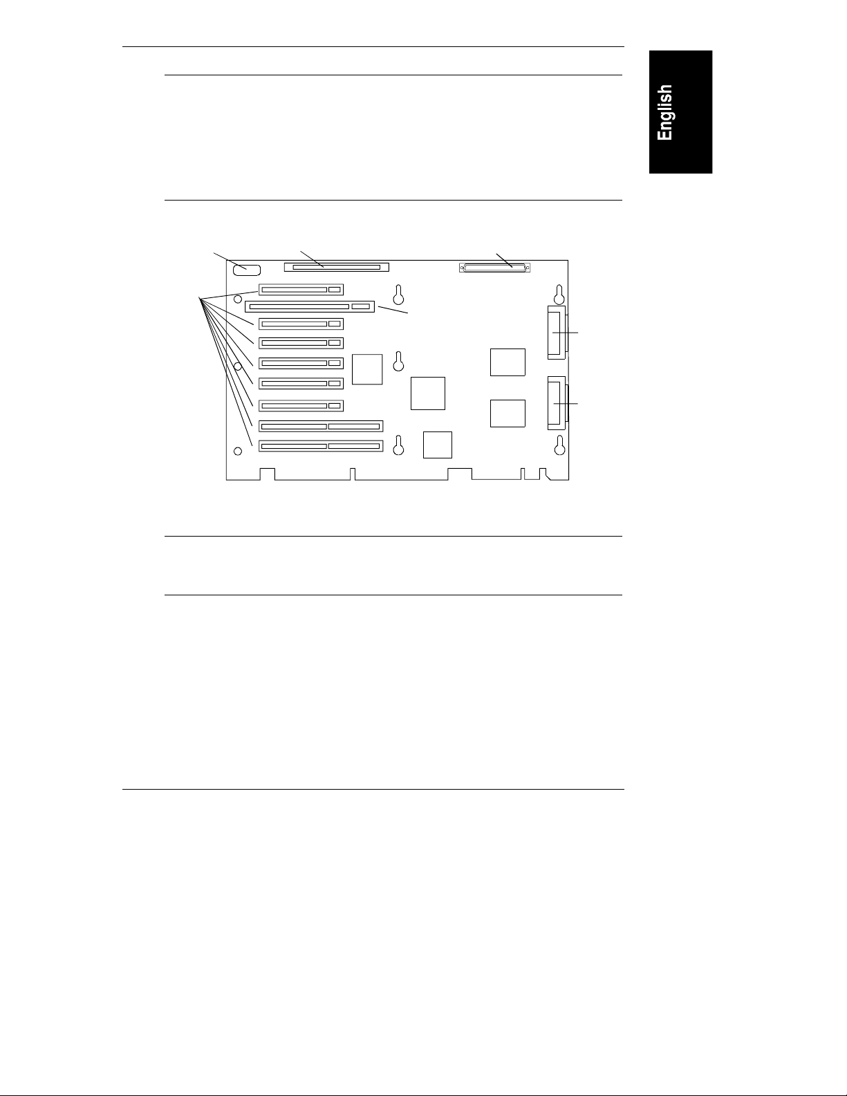
4 Accessory Boards
The HP NetServer accepts PCI and I S A accessory boar ds connected to th e I /O
Board. An accessory board can be identified by the offset of the bracket and the
shape of the edge con nector (see Figure 4-1).
PCI Board- Left-Side Offset
ISA Board- Right-Side Offset
Figure 4-1. I/O Board with Devices and Bus Structur e
The I/O Boa rd
The I/O board is located under cover 1 and is sh own in Figure 4-2. The I/O board
contains:
• The Remote Managemen t connector, linking the I/O board to the external
conn ector on the rear panel.
• The I/0 Memory slot, which contains cache memory used by the Intel
i960RD I/O processor.
• The SE SCSI connector, wh i ch services an y sin g l e-ended SCSI device
installed in the internal (non-hot-swap) trays.
• The PCI Boa rd sl ot s , which are eig ht connect ors that accept PCI boar d s .
• The I SA Board slot, wh ich accepts a single I SA board. Th is slot is shared
with PCI slot 1. Either slot can be occupied, but not both.
• The two SCSI connectors, A and B.
17
Page 24

Chapter 4 Accessory Boards
SCSI A has the following characteristics:
• By default, SCSI channel A is conn ected to the hot-swap mass
storage cage that was shipped with the NetServer. (For the HP
NetSer ver LH 4, SC S I A i s connected to t he r igh t cage; for th e HP
NetSer ver LH 4r, SCSI A is connected to th e lower drive cag e.
• By default, the integrated HP NetRAID subsystem is enabled for
SCSI A.
SCSI B h as the following characteristics:
• By default, SCSI channel B is connected to the non-hot-swap
devices. If you install a second h ot-swap mass storage cage, you
can connect it to SCSI B. There are two SCSI B connectors: one
SCSI B connector is designed for the single-ended (SE), non-hotswap devices; the other SCSI B connector supports Ultra2 (LVD)
drives. The two connectors are on th e same SCSI bus, but are
separated electrically by an LVD to SE converter. The slow
devices on SE are not affected by LVD operation. However, SE
devices and LVD devices cannot share a SCSI ID. To resolve a
conflict, change the SCSI address of the non-hot-swap device by
resetting its SCSI address switches.
18
• By default, the integrated HP NetRAID subsystem is disabled for
SCSI B. However, you may enable the integrated HP NetRAID
subsystem on SCSI B.
• If you enable HP NetRAID for SCSI B, all non-hot-swap SCSI
devices and all hot-swap drives in the second hot-swap mass
storage cage become par t of HP NetRAID.
• If you enable HP NetRAID for SCSI B, you cannot use devices
with multiple LUNs (logical units) in the non-hot-swap shelves.
An example of a device with multiple LUNs that you cannot use is
an autoloader tape device. If you want to use a device with
multiple LUNs and you want to enable HP NetRAID for SCSI B,
you must con nect t he device to a SCSI controll er access ory board.
• If you enable HP NetRAID for SCSI B, and you plan to use a tape
backup device, you m ust connect th e device to a SCSI controller
accessory board.
Page 25
Chapter 4 Accessory Boards
NOTE If you enable NetRAID on only one channel, it is
recommen ded that you use the default configuration and
enable HP NetRAID on SCSI A. f you enable HP NetRAID on
only one channel, and later want to enable a second channel,
you must follow the instructions in the Integrated HP
NetRAID Controller Configuration Guide in the chapter on
configuring a secon d chann el.
Remote
Management
PCI Board
Slots
I/0 Memory SE SCSI
ISA Board Slot
SCSI B
SCSI A
Figure 4-2. I/O Board With Devices and Bus Structure
NOTE For a list of boards HP has tested with the NetServer, see the
Help topic "Tested Parts List" on the HP NetServer Navigator
CD-ROM.
Installing Accessory Boards
Remove cove r 1 from th e N e tServer. (See C ha pter 3, "Removing an d Replacin g
Covers.")
To install accessory boards:
1. Read the documentation included with each accessory board. Follow any
special instructions and installation recommendations. Some boar ds have
19
Page 26
Chapter 4 Accessory Boards
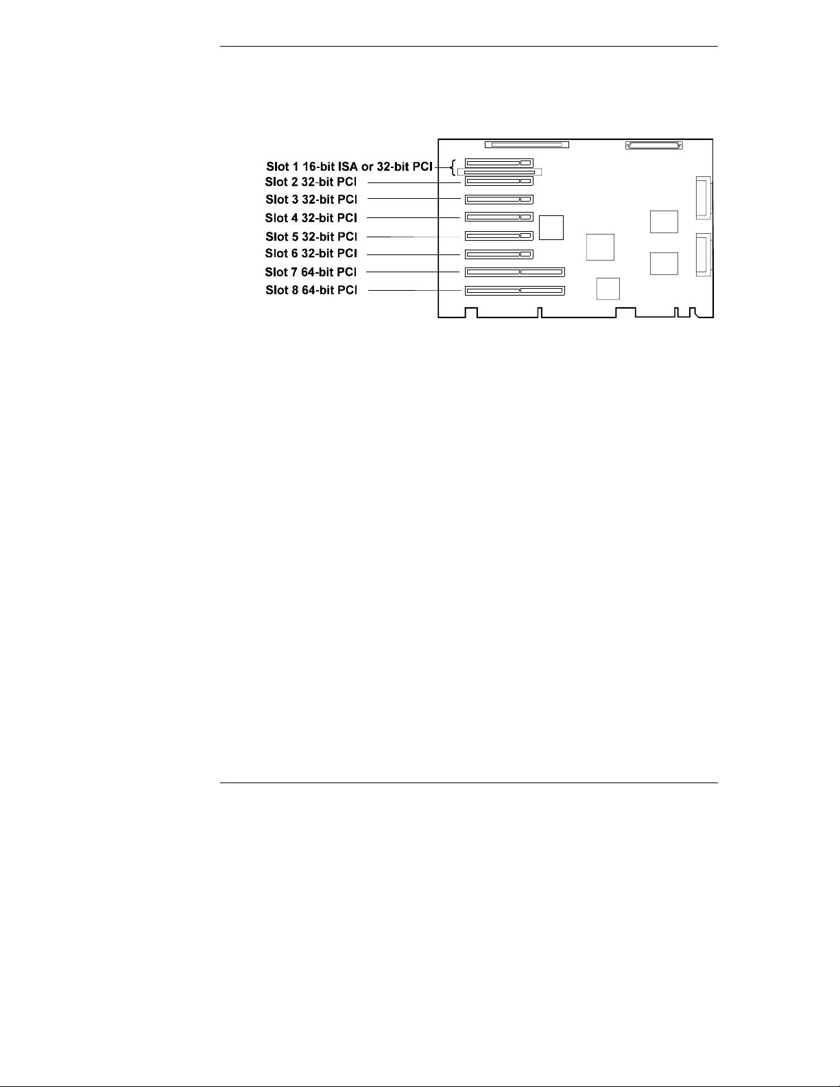
prefer r ed slot locations. If not, consider the boot order (see F igu re 4-3)
when choosing the accessory board socket in wh ich to install the board.
Figure 4-3. Accessory Board PCI and ISA Slots
Boot order for PCI c ont rol lers is dete rm in e d by slot location. The system
searches for a bootable device in the following order:
a. IDE CD-ROM drive with a bootable CD-ROM.
b. Flexible disk drive with a bootable flexible disk.
c. Embedded SCSI controller or HP integrated NetRAID controller.
d. PCI boards in slots in the following order: 8, 7, 6, 5, 4, 3, 2, 1.
This boot or der c an be c ha nge d usin g the Setup utility (press [F2] during
the boot p rocess).
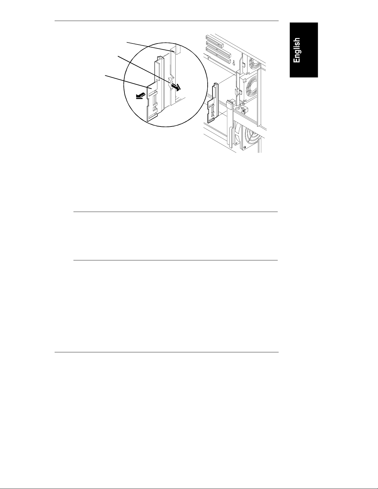
2. Re move t he slot c over for ea ch slot to be us e d, and st ore it for future us e.
If you are installing any full-length PCI boards, also remove the accessory
board retainer (see Figur e 4-4). Push on the tab on the retainer to release
it, and then slide it out of the boar d guide.
20
Page 27
Chapter 4 Accessory Boards
Accessory Board Guide
Release Tab
Accessory
Board
Retainer
Figure 4-4. Accessory Board Retainer and G ui de
3. Install the boar ds. Insert each boar d in th e desired slot an d fasten the
board’s mounting scr ew at the slot opening at the rear of the chassis.
Connect any required cables to the boa rds. If you removed the board
retainer, reinstall it.
NOTE If you install an ISA non-Plug-and-Play board, you must
reserve system resources (some or all of: memory addresses,
I/O addresses, IRQs, and DMA cha nnels) for i t. Wri t e d own
that information now for reference when you reserve system
resources. See "Configuring the NetServer" for details of using
ISA Plug and Play boards.
4. Replace cover 1. (See Chapter 3, "Removing and Replacing Covers.")
21
Page 28

Page 29
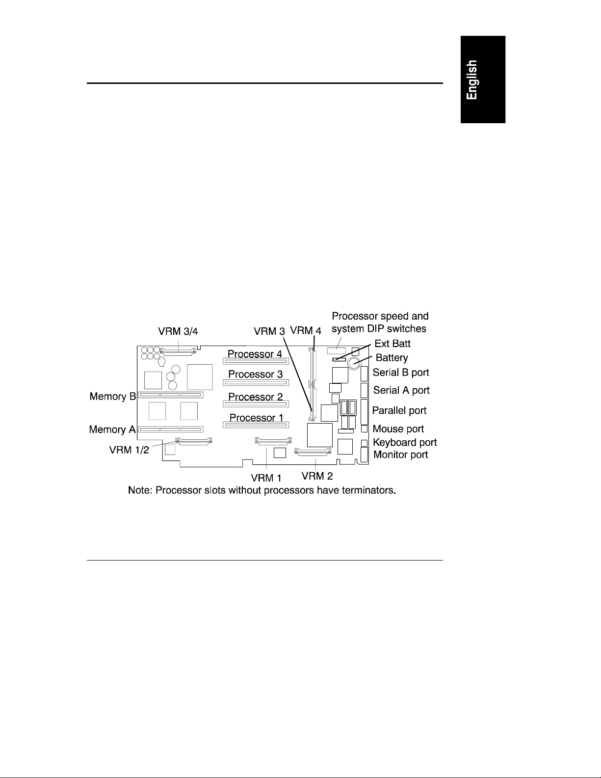
5 Installing A dditional Memory
The two memory boards (Memory A and Memory B) are located on the System
board assembly, beneath the memory cage cover. Both memory boards are
required. Ea ch board h as slots for eight DIMMs.
The followin g r ules must be observed when adding memory:
• DIMMs are a dd ed four a t a time - two per memory car d. Th e memory
cards must be balanced.
• DIMMs are i nstalled in banks, 1 through 4.
J1 and J2 of Memory A and B are bank 1
J3 and J4 of Memory A and B are bank 2
J5 and J6 of Memory A and B are bank 3
J7 and J8 of Memory A and B are bank 4
• DIMMs must be 64 or 256 Mbytes, EDO buffered TSOP 50 ns.
• DIMM types cannot be mixed in a ban k.
Figure 5-1. System Board
23
Page 30
Chapter 5 Installing Additional Memory
NOTE Use only HP DIMMs listed in HP Information Assista nt or HP
Order Assistan t.
Installing Additional Memory in the LH 4
1. Turn OFF t he NetServer a nd r emove all cables from the rear of the
NetServer. Pull both power plugs out.
2. Remove cover 3 and the bezel (see Chapter 3, "Removing and Replacin g
Covers").
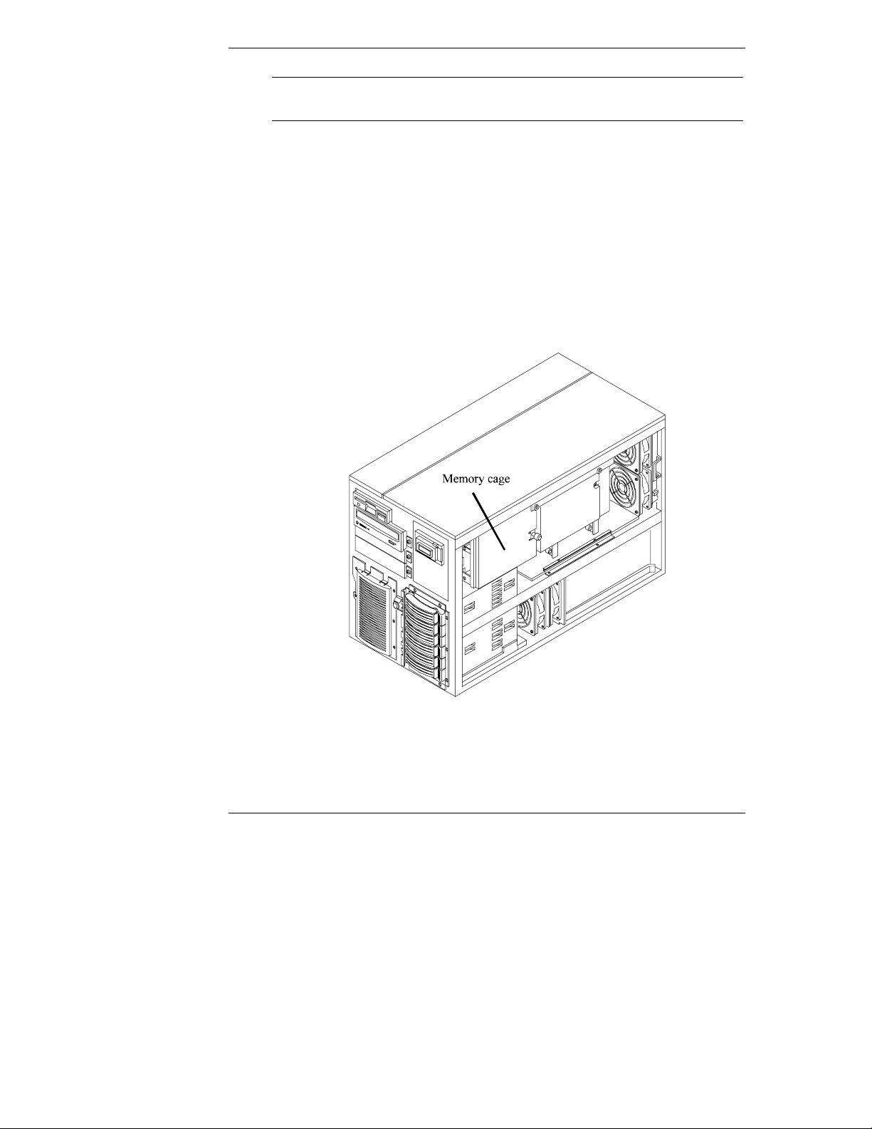
3. Loosen the memor y cage s crew, and swing t he cover open (see Figure 5-
2).
Figure 5-2. Memory Cage
4. Unseat each memor y board with the release clips, and remove the two
boards (see Figure 5-3).
24
Page 31

Chapter 5 Installing Additional Memory
Figure 5-3. Removing Memory Boards
5. At your work station make sure you are protected from static electricity.
Install the DIMMs (see Figure 5-4):
a. Remove a DIMM from its container, handling th e module by its edges.
Lay it on an an ti-static surface.
b. Choose the socket in to which you will install a DIMM. DIMMs are
installed four at time: two per board. DIMMs must be TSOP 50 ns 64
or 256 Mbytes, with no size mixin g per bank. DIMMs are installed
starti ng a t J1 and proceed to J8 .
c. Spread the two latches on th e socket outwar d.
d. Align the notches on the DIMM with the keys on the socket.
e. Holdin g t he DIMM at 9 0 d egrees to the system board, press the DIMM
fully into the socket until the latches close. If the clips do not close, the
DIMM is not inserted correctly.
25
Page 32

Chapter 5 Installing Additional Memory
Figure 5-4. Inser t i ng DI MM Into Memory Board
6. Repeat step 5 to install all of the DIMMs for you r memor y configur ation.
7. Reinstall the memory boards. Memory A and Memory B need to be
identical, so they are interchangeable in their sockets.
8. Close th e memory cage cover and tighten the screw.
9. Repl ace the cover.
10. Restore el ectri cal con nections.
Installing Additional Memory in the LH 4r
NOTE How to change the memory in a r acked NetServer depends on
how high (or low) in the rack it is mounted. If there is room
underneath the extended NetServer to reach up from below
into the memor y cage, the System board assembly can remain
inside the NetServer. These instructions assume you need to
remove the System board assembly.
If you can reach the memor y cage, pr oceed as for the LH 4.
1. Turn OFF t he NetServer a nd r emove all cables from the rear of the
NetServer. Pull both power plugs out.
26
Page 33

Chapter 5 Installing Additional Memory
2. Remove cover 2 (see Chapter 3, "Removing and Replacing Covers").
3. Remove the four screws holding the System board assembly secure on top.
Remove the system board assembly by r aising th e retaining latches to
disengage it from the socket, then pull it out until it clears the chassis
guides (see Figure 5-5). Set the system board assembly down on a work
surface, metal plate side down.
Figure 5-5. Removing System Board f r om LH 4r
4. Loosen the memory cage screw, and r emove the cover by sliding it slightly
up to unlock it.
5. Unseat each memor y board with the release clips, and remove the two
boards (see Figure 5-6).
27
Page 34

Chapter 5 Installing Additional Memory
Figure 5-6. Removing Memory Boards
6. At your work station make sure you are protected from static electricity,
install the DIMMs (see Figure 5-4):
a. Remove a DIMM from its container, handling th e module by its edges.
Lay it on an an ti-static surface.
b. Choose the socket in to which you will install a DIMM. DIMMs are
installed four at time: two per board. DIMMs must be TSOP 50 ns, 6 4
or 256 Mbytes, with no size mixin g per bank. DIMMs are installed
starti ng a t J1 and proceed to J8 .
c. Spread the two latches on th e socket outwar d.
d. Align the notches on the DIMM with the keys on the socket.
e. Holdin g t he DIMM at 9 0 d egrees to the system board, press the DIMM
fully into the socket until the latches close. If the clips do not close, the
DIMM is not inserted correctly.
7. Repeat step 6 to install all of the DIMMs for you r memor y configur ation.
28
Page 35

Chapter 5 Installing Additional Memory
8. Reinstall the memory boards. Memory A and Memory B need to be
identical, so they are interchangeable in their sockets.
9. Close th e memory cage cover and tighten the screw.
10. Carefully reinsert the System board assembly into its guides, and r eseat it
into its socket by returnin g th e retain clips flat.
11. Reconnect cables and power cord s t o the of the NetS erver.
12. Replace the cover 2 (see Chapter 3, "Removing and Replacing Covers")
and return the NetServer in to the rack.
29
Page 36

Page 37

6 Installing Mass Storage Devices
The NetSer ver chassis has space for two hot-swap m a ss storage shelves, an d is
shipped with a single hot-swap mass stor age cage. If you need more storage than
your configuration allows, you can purchase th e HP NetServer Mass Storage
Upgrade Kit to obtain a second hot-swap mass storage cage. Like the primary
cage, the secondar y cage can h old up to six low-profile Ultra2 hot-swap hard disk
drives.
There are two empty shelves i n the n on-h ot -swap shelf area. Th es e shelves can be
used to install 3.5-inch or 5.25-inch SE SCSI mass storage devices, LUN tape
dri ves, or ot her HP- tested accessories.
Supported Mass Storage Devices
NOTE Do not mix high voltage differential (HVD) driver an d
receiver devices wi t h wit h SE, LVD, or multimode driver and
receiver devices on the sam e S C SI bus. I /O circuit s u s ed by
devices with SE, LVD (Ultra2) or multimode driver s and
receivers do n ot operate at HVD levels and s hould never be
exposed to HVD environments. If you mix SCSI SE a nd SCSI
LVD (Ultra2) devices, system performan ce will be adversely
affected. F or best perform ance, use only LVD devices.
The NetServer supports two classes of ma ss storage devices: SCSI devi ces
installed in the two non-hot-swap shelves next to the CD-ROM player and the
flexible disk drive, and the Ultra2 SCSI h ot-swap hard disk drives installed in the
hot-swap mass storage cage. If you need additional mass storage capacity, you
can order a second hot-swap mass storage cage. Use on ly high-performance
Ultra2 hot-swap drives in the hot-swap mass storage cage.
You can add any standard (non-Ultr a 2) wide, single-ended SCSI device in the
two non-hot-swap shelves, such as removable hard disk drives or tape backups.
Use the SE connector on the pr ovid ed cable.
For the latest list of HP-tested products, refer to the "Tested Products List" Help
topic on the HP NetServer Navigator CD-ROM.
31
Page 38

Chapter 6 Installing Mass Storage Devices
Table 6-1. Supported SCSI Devices
Locatio n Drive Typ es
Hot-Swap Mass
Storage Shelves
Non-Hot-Swap Mass
Storage Shelves
4.2, 9.1, or 18.2 GB Ultra2 7200 r pm or 10K rpm
drives (up to 35W power consumption)
4.2 or 9.1 GB Ultra Wide or Single-Ended
SCSI Drives, 7200 rpm
DAT backup systems or Tape Drives (DLT, DDS,
autoloader)
SCSI A ddr essing
NOTE Do not set up any devices with SCSI address 7. This address is
reserved for the SCSI controller.
Hot Swap Drive Cage Addresses
The HP NetSer ver comes with a single hot-swap mass storage cage installed. In
the HP NetSer ver LH 4, the cage is on the lower right front. In the HP NetServer
LH 4r, the cage is at the lower left front.
The SCSI addressing sch eme associated with the hot-swap mass storage cage
begins with SCSI address 0, and continues with addresses 1, 2, 3, 8, and 9.
You can in stall a second hot-swap mass stor age cage. Addresses in th e second
cage are independent of the drive addresses in the primary cage. Do not install a
narrow SCSI drive in any hot-swap mass storage shelves with an address higher
than 6. Narrow SCSI is limited to SCSI addresses 0 - 7, and the NetSer ver will
not be able to communicate with it.
Other SCSI Device Addresses
SCSI devices installed in the two non-hot-swap shelves next to the flexible drive
and CD-ROM drive are attached to the SE SCSI con n ection, and must use a
SCSI address that does not conflict with the SCSI addresses used by drives in
hot-swap mass storage shelves. Do not in stall a nar r ow SCSI drive in any
location with an address higher than 6. Narrow SCSI is limited to SCSI
addresses 0 - 7, and the NetServer will not be able to communicate with it.
32
Page 39

Chapter 6 Installing Mass Storage Devices
Hot-Swap Mass Stor age
The Ultra2 SCSI hot-swap hard disk drives for mass storage come in two heights:
the 1-inch low-profile drive and the 1.6-in ch half-height drive.
The Ultra2 drives are LVD (low voltage differential) drives, wh ich allow the
integration of the differential drivers and receiver s into SCSI drive contr ol lers .
Ultra2 tech n ology provides increased signal quality and ensures the same data
integrity as the previous high voltage differential designs at a reduced cost. With
the low voltage design, th e SCSI bus cable can exten d up to 12 meters.
CAUTION Do not mix devices with high voltage differential (HVD)
dri vers and receiver s and d evices with SE, Ul tra 2 or
multimode drivers and receivers on the same SC SI bu s. I/O
circuits used by devices with SE, Ultra2 or multimode drivers
and receivers do n ot op erat e at HVD level s and shoul d never
be exposed to HVD environment s. If you mix SCSI SE and
SCSI Ultra2 devices, system per formance will be adversely
affected. F or best perform ance, use only Ultra2 devices.
Each Ultra2 disk drive module has two LED apertures: one for power status and
one for activity status. Light pipes on the module transmit light to these apertures
from LEDs on the inside rear of the hot-swap mass storage cage. The display
meanings are described in Table 6-2.
Table 6-2. Hard Disk Drive LED I ndi cat i ons
Power Status LED Activity Status LED
Off: Disk not present, or not
Off: No disk activity
conn ected to the cag e
Green (solid): Disk present Green (flashing): Accessing d i sk
Green (Solid for more than one minute):
Disk spinning up, or "hung"
Amber (flashi ng ): Disk failure predicted
Red (solid): Disk failed
33
Page 40

Chapter 6 Installing Mass Storage Devices
Filler Pane ls
When you have fewer drives than the hot-swap mass storage cage supports, a
1-inch filler panel must be inserted in each empty disk location. Filler panels
ensure that drive cage has the proper ventilation and air flow. Remove the filler
panel when you insert a new dr ive.
CAUTION The filler panels serve an important purpose by helping the
internal components ventilate and preventing excessive
electromagnetic radiation. If these fillers are left out of the
drive shelves, th ermal damage and/or excessive EMI could
occur.
Drive Spacers
When your drive cage holds a mix of 1-i nch and 1.6-i nch drives, you may need to
add 0.5-inch drive spacers. The drive spacer fills the gap between adjacent drives
or between a drive and a filler panel. Disk spacers can be mounted on 1-inch
low-profile drives or 1.6-inch half-height drives, so a drive spacer and lowprofile drive are the same size as a half-height drive, and a drive spacer and a
half-height drive ar e as large as two low-profile drives.
CAUTION The drive spacers serve an important purpose by helping the
internal components ventilate and preventing excessive
electromagnetic radiation. If these drive spacers are left out of
the drive shelves, thermal damage and/or excessive EMI
could occur.
Configurations
Figure 6-1 shows the supported configurations of SCSI hot-swap hard disk drives
in both versions of the NetServer. The arrows indicate the order that you insert
hard disk drives.
These configurations may use filler panels and drive spacers to close up the front
of the hot-swap mass storage cage. If there are gaps in th e cage, the drives may
not receive the proper ventilation and could suffer thermal damage.
•
If you have an HP NetServer LH 4, add hard disk drives starting from the
bottom of the hot-swap mass storage cage. If you are using one or more
filler panels, insert them at the top of the ca ge.
34
Page 41

Chapter 6 Installing Mass Storage Devices
• If you have an HP NetServer LH 4r, add h ard disk drives starting from the
left. If you are using one or more filler panels, insert them on the right
side of the drive cage.
NOTE Do not install a narrow SCSI drive in any location with a
SCSI address greater th an 6. Narr ow SCSI is limited to SCSI
addresses 0 - 6, and the NetServer will not be able to
communicate with a narrow SCSI drive.
35
Page 42

Chapter 6 Installing Mass Storage Devices
36
Figure 6-1. Hot - Swap Drive Configurat i ons
Page 43

Chapter 6 Installing Mass Storage Devices
Installing a Hot-Swap Hard Disk Driv e
CAUTION Protect the drive fr om static electr icity by leaving it in its
anti-static bag until you ar e ready to install it. Before
handling the drive, touch any unpainted metal surface to
discharge static electricity. When you remove the drive from
the anti-static bag, h an dle it only by the frame.
Do not touch th e electrical compon ents . Pla ce the d rive on
the anti-static bag whenever you set it down.
Hard disk drives are very susceptible to mechanical shock and
can be damaged by a drop as short as one-quarter of an inch.
Take care when unpacking and handling the drive. If the
drop would crack an egg, it will damage the drive.
1. If there is a filler panel in the hot-swap mass storage location, remove the
filler as follows:
•
Press the locking latch.
•
Pull the filler panel straight out (see Figure 6-2).
37
Page 44

Chapter 6 Installing Mass Storage Devices
Figure 6-2. Rem oving a Mass Storage Filler Panel
2. Drive spacers attach to the disk drive module with four small feet. If you
need to remove a drive spacer from the adjacen t disk drive module,
remove it as follows:
38
•
Slide the drive spacer back, a fraction of an inch away from your body.
•
Tilt up the front of the drive spacer to disengage the fr ont two feet.
•
Pull the drive spacer forward slightly to disengage the back two feet
and lift (see Figure 6-3).
Page 45

Chapter 6 Installing Mass Storage Devices
Drive Spacer
Figure 6-3. Rem oving the Drive Spacer
3. On the drive, press the locking latch in and pull the ejector han dle out as
far as it can go, as shown in Figur e 6-4.
CAUTION Be careful when you open th e ejector handle. Ext reme force
can snap off the handle.
39
Page 46

Chapter 6 Installing Mass Storage Devices
Locking tab retracts
when the ejector
handle is open
Light Pipes
(fragile)
Ejector Handle
Locking Latch
Figure 6-4. Readying Drive for I nst al lation
4. Slide the drive slowly into the location until it stops (see Figures 6-5
and 6-6).
CAUTION Be car eful not to damage the light pipes as you insert the
drive. They are very fragile.
You must insert the drive sl owly and gently. If the drive is
ins erted t oo qu ickly when the system is on, i n-rush cur ren t
can cause the power supply to shut down.
5. Press the ejector handle in until you feel the latch click into place. Closing
the ejector handle engag es the d rive wit h the elect rical connector in the
hot-swap mass storage cage and seats the drive. If the drive is unseated in
the cage after closing the ejector handle, the handle was probably not
pulled out far enough, and the locking latch failed to engage the hot-swap
mass s t orag e ca ge. Repea t th e procedu re from s tep 3.
40
Page 47

Chapter 6 Installing Mass Storage Devices
Make sure the ejector handle
is open when you insert the drive
Figure 6-5. Inst al ling a Drive in the HP NetServer LH 4
Make surethe ejector handle
is op en when you insert the drive
Figure 6-6. Inst al ling a Drive in the HP NetServer LH 4r
41
Page 48

Chapter 6 Installing Mass Storage Devices
Removing a Hot-Swap Hard Disk Drive
CAUTION You must remove the drive slowly to ensure that the drive
heads are parked prior to removal. Be sure to follow these
instructions car efully to prevent handling damage, such as
head slaps or h ead actuator unlocking.
1. To unlock the drive, push the locking latch in and then pull the ejector
handle toward you.
2. Gently pull the drive out about an inch to disengage th e power connection.
3. Wait about 30 seconds for the drive to stop spinning and the drive heads
to park.
4. Use your hand to support the bottom of the drive. Slowly pull the dr i ve
straight out. Do not allow the drive to fall.
5. If you are removin g the drive from an HP NetServer LH 4r, turn the drive
slowly to its horizontal storage orientation.
6. Place the drive in an electrostatic protected container. Do not stack drives.
Integrated HP NetRAID
The HP NetSer ver contains an integrated HP NetRAID controller, which puts the
power of the HP NetRAID series of DACs (disk array contr ollers) in th e
NetSer ver with no additional hardware.
HP NetRAID tech n ology lets you link multiple hard disk drives together and
write data acr oss them as if they were one large drive. With the integrated HP
NetRAID controller, you can configure your linked drives in to a RAID
(Redundant Arra y of Independent Disks) subsystem.
Refer to the Integrated HP NetRAID Controller Configuration Guide for
complete information. You can also find the guide on the following HP website:
http://www.hp.com/
42
Page 49

7 Installing A dditional Power Supplies
The NetServer is shipped with two power supply cages. One power supply cage
contains two power supplies, and one power supply cage contains one power
supply, with th e empty half covered wit h a protective panel. The NetServer
operates with just three power supplies; adding an additional power supply makes
continuous operation possible if a power supply fails.
Figure 7-1. Power Suppl i es and Optional Power Suppl y Bay
If you desire an additional power supply for redundancy, you can purchase the
HP NetServer Power Supply Upgrade Kit.
Installing an A dditional Power Supply
Refer to the HP Power Supply Upgrade Kit Instal lat i on Guide for instructions on
how to install additional power supplies.
43
Page 50

Chapter 7 Installing Additional Pow e r Supplies
Ventilating Fans
HP NetServer fans are placed to ven tilate and cool internal components. The LH
4 and LH 4r use a redundant fan assembly with two fans that mount directly in
front of the fans cooling th e power supplies. In general, if any one fan fails, the
NetSer ver will con tinue to operate, but if two fans fail, thermal shutdown will
occur.
CAUTION The NetServer must have its covers in place for proper
cooling. If you open the NetSer ver while it is operating, do
not run it for more than three minutes.
Do not run the NetServer for more than two minutes without
at least one wor kin g fan in th e fan assembly mounted
immediately behind the power supplies or in the exhaust fa n
assembly. Failure to observe th ese precautions may result in
thermal damage to the NetServer.
Servicers can h ot - s wa p any fan ex cept the processor fa n. I f
this fan fails, or if the metal baffle is r emoved, thermal
damage to the NetSer ver can occur.
44
Page 51

8 Installing the NetServer in an HP
Rack System/E or Rack System/U
This chapter lists the steps required to install the rack-optimized HP NetSer ver
LH 4r (see Figur e 8-1) in an HP Rack System/E/U.
NOTE The pedestal mounted HP NetSer ver LH 4 can n ot be rack
installed without a con version kit. Contact your HP reseller for
information about the HP NetServer LH 4 to LH 4r
Conversion Kit.
Figure 8-1. NetSer ver Conf igurations
Steps for installing the NetServer in an HP Systems rack are listed in Appendix
A, "Installing the NetServer in an HP Systems Rack."
If you are mounting the NetServer in a non-HP rack, refer to the separate rack
mounting guide for third party racks. It is packed in the accessories tray in the
HP NetServer’s shi p ping box.
45
Page 52

Chapter 8 Installing the NetServer in an HP Rack System/E or Rack System/U
Preparing for Installation
You should plan the placement of your HP NetServer LH 4r and other rack
components befor e p roceeding with i nstallation. Proper placement is vital for
both safety and operating efficien cy. For more details, see the HP NetServer Rack
Installation Road Map and the HP Rack System/E User Manual or the HP Rack
System/U User Manual.
STOP! Read the HP NetServe r Rac k Instal l ati on R oadmap before
installing the HP NetServer LH 4r. The roadmap contains
important information you need to kn ow for installing
components in the rack.
HP Rack Assistant ca n be used to plan the rack configuration. HP Rack Assistant
can be down loaded from the following web site:
http://www.hp.com/
The rack-optimized HP NetServer LH 4r fits into 19-inch-wide EIA (Electrical
Indust ry Association) racks. Vertical space in th e rack is measured in standard
EIA units. One EIA un it i s 1.75 i nches (44.45 mm). Th e HP NetServer LH 4r
requires 8 EIA units of space.
Preven t Rack Tip-Over, E quipmen t Damage an d In jur y
WARNING To prevent the rack from tipping over, e xtend the anti-tip
foot from under the front of the enclosure prior to
mounting any components. Also lower the leveler feet at the
four corners of the rack to improve stability an d prevent the
rack from rolling away as devices are inserted into their rack
mounts. Failure to use the anti-tip foot and leveler feet could
result in serious injury.
CAUTION The HP NetServer LH 4r weighs up to 160 pounds (73 kg.)
when fully loaded. Take out power supplies and hot-swap
hard disk drives before lifting the NetServer into the rack.
Use two people when moving the NetSer ver or lifting it into
the rack .
46
Page 53

Chapter 8 Installing the NetServer in an HP Rack System/E or Rack System/U
The hardware used in this installation is shown in Figur e 8-2.
Figure 8-2. Identifying Instal l a t i on Har dware
Tools Required
The following tools are required to in stall the NetServer:
• T15 TORX
• T25 TORX
• Phillips head screwdriver
• Hewlett-Packar d NetServer LH 4r Rack Template
• Tape or a marker pen to mark mounting location s
driver
driver
47
Page 54

Chapter 8 Installing the NetServer in an HP Rack System/E or Rack System/U
Installing the Slides
The followin g steps and illustrations describe how to install slides for mounting a
NetServer.
Marking the Colu mns
Hole position for rack nuts and bar nuts need to be determined. Mark the
mounting location of the NetServer an d mounting holes on each column of the
rack. Mark the mounting holes on each column of the rack as described below.
NOTE The EIA unit marks are stamped in the sheet metal of the
columns. Use the rack template to mark the correct holes for
mounting (on all four column s).
Marking Fr ont Colum ns
Mark the slide mountin g h oles on the front columns.
1. Mark the base line (bottom) of the NetServer at an EIA unit mark on the
column.
2. Hold the bottom of the rack template at the base line. Mark the top of
NetSer ver (8 EIA units counted up from the base line).
3. Mark th e slide screw mounting holes (holes 20 and 22 counted up from
the base lin e).
4. Mark the second front column by r epeating steps 1 through 3.
Marking R ear Columns
Mark the slide mounting holes on the inside faces of the rear columns.
1. Mark the base line (bottom) of the NetServer at an EIA unit mark on the
column.
2. Hold the bottom of the rack template at the base line. Mark the top of
NetSer ver (8 EIA units counted up from the base line).
3. Mark the slide mounting hole (hole 21 counted up from the base lin e).
4. Repeat steps 1 through 3 and mark the second rear column.
48
Page 55

Chapter 8 Installing the NetServer in an HP Rack System/E or Rack System/U
Installing Rack Nu ts
Rack nuts are installed on th e front columns to secure the bezel latch and hinge.
Use the rack template to locate the mounting holes (see Figure 8-3).
Rack nuts are installed on th e rear columns to secure the z-bracket, which is
secured to the NetServer. Use the rack template to locate the mounting holes.
1. Install the bezel latch rack nuts on the right front column (holes 11 and
15 counted up from the base line).
2. Install the bezel hinge rack nuts on the left front column (holes 6 and 19
counted up from the base line).
3. Install the z-br acket rack nuts on the right rear column (h oles 9 and 13
counted up from the base line).
Install rack nuts at
holes 9 and 13 up
from base line
Top is
8EIA
units from
base line
Install rack nuts at
holes6and19up
from base line
Base line
Figure 8-3. Marking the Columns for Rack Nuts
Install rack nuts at
holes 11 and 15 up
from base line
)URQW
Template
49
Page 56

Chapter 8 Installing the NetServer in an HP Rack System/E or Rack System/U
Installing Bar Nu ts
The "bar nut" is a two-hole metal bar used to secure the mounting flanges of the
slide to th e rack columns.
All four mounting brackets on th e slides attach behind the outside faces of the
columns, using bar nuts. Use the template (or if you no longer have it, count) an d
mark the 20th and 22nd holes up from base line on each column. These holes
correspond to the bottom hole of the eighth EIA unit (and the middle hole of the
7th E IA uni t) a bove base line (s e e F igu re 8-4).
Figure 8-4. Marking the Rack Columns for Bar Nuts
The bar nut is placed behind the outside face of the column, at the corr ect height
as determined with the template, or by counting. Two screws ar e inserted through
the correct h oles on the front columns. Start (but do not tighten) both scr ews in
the bar nut (see Figure 8-5).
50
Page 57

Chapter 8 Installing the NetServer in an HP Rack System/E or Rack System/U
Figure 8-5. How to Attach Bar Nuts
The slots in the mounting flange allow you to in sert the flange in place behind
the outside face but in front of th e bar nut.
Hold the bar nut behind the outside face of the column at the slide screw holes
marked earlier. Start (but do not tighten) two screws through the face of the bar
nut. Install the bar nuts on all four rack columns.
The mounting flanges are then positioned behind the column face, but in front of
the bar nuts.
Attachin g the Slides
The slides have mounting flanges at each end (see Figure 8-6). The mounting
flange is inserted between the column and th e bar nut.
51
Page 58

Chapter 8 Installing the NetServer in an HP Rack System/E or Rack System/U
Figure 8-6. Posit i oni ng t he Sl ides
NOTE The slide members cannot be removed.
1. Hold the slide so the slide members extend out the front of the rack.
2. Insert the slide front and rear mounting flanges between the column and
bar nuts. Press the slide firmly against each rack column (see Figure 8-7).
52
Page 59

Chapter 8 Installing the NetServer in an HP Rack System/E or Rack System/U
Figure 8-7. Securing Sl ide to the Rack Column
3. Tighten both screws into the mounting flanges of each end of each slide.
53
Page 60

Chapter 8 Installing the NetServer in an HP Rack System/E or Rack System/U
Installing the NetServer
The followin g steps require liftin g th e NetServer and securing it to the slides
installed in the rack.
WARNING Extend the anti-tip foot from the front of the rack and lower
all leveler feet to stabilize the rack before mounting rack
components. Failure to use th e anti-tip foot and leveler feet
could result in serious injury.
1. Lower the four rack leveler feet to the floor , lifting the rack off the rack
wheels (see Figure 8-8).
2. Fully extend the anti-tip foot from the front of the rack.
Figure 8-8. Prepari ng the Rack for NetServer Installation
54
Page 61

Chapter 8 Installing the NetServer in an HP Rack System/E or Rack System/U
3. Extend the slides until you hear a click, indicating they are locked. Note
that slides do not come apart.
4. Remove power supplies and ha rd disk drives from the server to reduce the
total weight to be lifted.
WARNING Two people are required to move or lift the NetServer. The
HP NetServer LH 4r weighs up to 176 pounds (80 kg.) when
fully loaded.
5. Lift the NetServer by the handles until the handles are above th e extend ed
slide members (see Figure 8-9).
6. Move the NetServer toward the rack, between the slide members, until all
four NetServer h an dles are over the slide members. The NetServer must
be slid onto the slides through the handles. You cannot lower it onto the
slides.
Figure 8-9. Mounting the Net Ser ver on t he Sl ides
55
Page 62

Chapter 8 Installing the NetServer in an HP Rack System/E or Rack System/U
7. Rest the NetServer handles on the slides and then lin e up the mounting
holes in the NetServer chassis with the scr ew holes in the slides (see
Figure 8-10).
8. Insert three scr ews through each slide member into the NetServer.
Tighten all screws securely.
56
Figure 8-10. Securing the NetServer to the Sli des
Page 63

Chapter 8 Installing the NetServer in an HP Rack System/E or Rack System/U
9. Remove two screws fr om each handle and remove the all handles (see
Figure 8-11). Save the handles an d screws for future removal and
reshipping of the NetServer.
Figure 8-11. Removing M ount i ng Handles
Securing the NetServer to the Rack
The following steps secure the NetSer ver to the rack and install the front bezel.
1. Attach the bezel hinge to th e NetServer with three screws thr ough the
right edge of the bezel hinge and into the left front of the NetServer (see
Figure 8-12).
2. Attach the bezel latch to the right side of the NetServer with two screws.
57
Page 64

Chapter 8 Installing the NetServer in an HP Rack System/E or Rack System/U
3. Depress the slide lockout latches, and push the NetServer completely into
the rack (see Figure 8-12).
Figure 8-12. Slide Lockout Releases, Bezel Latch, and Bezel Hinge
4. Install two screws through the bezel h inge into the rack nuts on the left
column (see Figure 8-13).
5. Install two screws through the bezel latch in to the rack nuts on the right
column (see Figure 8-13).
58
Page 65

Chapter 8 Installing the NetServer in an HP Rack System/E or Rack System/U
Figure 8-13. Securing the NetServer to the Rack
6. Snap the bezel on the bezel hinge and close the bezel on the bezel latch.
The bezel swings open to access the NetServer in tern al mass storage cage
(see Figure 8-14).
Figure 8-14. Inst al ling the Bezel
59
Page 66

Chapter 8 Installing the NetServer in an HP Rack System/E or Rack System/U
7. Attach the z-brackets to the rear columns with two Torx screws, using the
T25 Torx driver. Fasten the bracket to the NetServer with two Torx
screws (see Figur e 8-15).
8. Slide the anti-tip foot into the rack.
9. Return to the HP NetServer Rack Installation Roadmap to complete the
rack installation.
60
Figure 8-15. Attaching the z-brackets to the NetServer and Rear Columns
Page 67

9 Connecting the Monitor, Keyboard,
Mouse, and UPS
Connect the monitor, keyboard, and mouse cables and the AC power cord to the
appropriate connectors on the rear of the chassis.
Figure 9-1. Rear View of LH 4/ LH 4r
If you have an uninter ruptible power supply (UPS), refer to the instructions
supplied with it. Install and turn on the UPS.
NOTE If you have installed your HP NetServer LH 4r into a rack,
refer to the Rack Cabling Reference for the HP NetServer LH
4/ LH 4r for in structions on how to cable the NetSer ver to
external connections.
61
Page 68

Chapter 9 Connecting the Monitor, Keyboard, Mouse, and UPS
The HP NetSer ver performs a diagnostic test wh en it is connected to an external
power source, and then performs another test when the power switch is turned
on. If an error condition occurs, note any error code appearing on the fron t pan el,
then refer to the troubleshooting section in Chapter 12.
62
Page 69

Chapter 10 Configuring the NetServer
10 Configuring the NetServer
The HP NetServer Navigator CD-ROM is shipped with your NetServer . You will
use this CD-ROM to configure your NetServer.
Contents of the NetServer Navigator CD-ROM
The M ain M enu of HP Navig ator d irects you to modul es where you can per form
configuration tasks or access onlin e system documentation. The menu buttons for
these modules are as follows:
• Readme File
• Configuration Assistant a nd Installation Assistant
• HP Management Solutions
• NetServer Utilities
• User Prefer ences
Before the HP Navigator Main Menu is displayed, you may be pr ompted to set
the language and the time and date. You can also set the language that the BIOS
displays.
The followin g is a description of the contents of the HP NetServer Navigator
CD-ROM, as accessed from th e Main Menu.
Obtaining NetServer Product History
When the NetServer is connected to its monitor, keyboar d, and power supply, you
are ready to begin installation and con figuration. As you configure the NetServer
for use, it is important to have the very latest configuration information. This will
inform you of an y applicable compatibility issues, and pr ovide you an up-to-date
list of HP-tested peripherals and accessories. Refer to the "Tested Products List"
on the HP NetServer Navi gat or CD-ROM.
You should also be familiar with HP DiagTools (on the HP NetServer Navigator
CD-ROM) and Information Assistant (on the HP NetServer Online
Documentation CD-ROM) to help you configure the NetServer.
Follow the instructions in your HP NetServer LH 4 (or LH 4r) Installation R oad
Map to complete these steps.
63
Page 70

Chapter 10 Configuring the NetServer
Readme File
This file includes t he most recen t information that was not available at the time
that the installation documentation was printed. It is impor tan t to check this file
before pr oceeding with the i nstallation.
Viewing the Readme File
1. Press the power-on button. Press the CD-ROM drive eject button. Place
the HP NetServer Navigator CD-ROM in the d rive, and p ress t he eject
button again to close the drive. Turn th e power off, wait 10 seconds, and
turn the power on again. If the system fails to boot, follow t he d iagn os tic
instructions on th e screen.
2. Go to th e HP Navigator Main Menu. If the language n eeds to be changed,
select User Preferences and the lan gua ge you want. You can also change
the language of the BIOS when prompted.
3. Select Readme File. The Readme file contains the latest information to
help you install your HP NetServer. Read it carefully before beginning
your in stallation.
Configuration Assistant and Installation Assistant
HP Configuration Assi stan t g u ides you thr oug h th e steps necessary to configu re
the NetSer ver. Three methods of configuration are available: Express, Custom,
and Replicate.
HP Installation Assi stant g u i d es you through the NOS in stallation and configures
the NOS with the a p propriate drivers for the HP-bundled configuration.
Before you run Configuration Assistant a nd In stallation Assista nt, you may need
to run the Symbios Configuration utility and th e Setup utility to do the following:
• If you need to verify or modify SCSI host adapter settings, or if you need
to low-level format SCSI disks or verify SCSI disk media, run the
Symbios Configuration utility. Refer to "Run Symbios Configuration
utility" later in this chapter.
• If you need to change the system defaults for enabling/disabling the
integrated HP NetRAID channels, run the Setup utility. Refer to "Setup"
later in this chapter.
64
Page 71

Chapter 10 Configuring the NetServer
• If you have installed an ISA non-Plug-and-Play accessory board, you must
reserve system resources for it. Refer to the "Configuring an ISA NonPlug-and-Play Board" later in this chapter.
Run Con figuration Assistan t and I nstallation Assistan t
Insert the HP NetServer Navigat or CD-ROM into the CD-ROM drive. Turn the
power off, wait 10 seconds, and turn the power on again. If the system fails to
start, follow the instructions on th e screen.
1. When HP NetServer Navigator starts, you may need to set the language,
time, and date. Follow the onscreen instructions. You can also change the
language of the BIOS when prompted.
2. Go to th e HP NetServer Navigator Main Menu and select "Configuration
Assistant an d I nstallation Assistan t ."
3. Follow the onscreen in structions in Configuration Assistant to contin ue
your NetServer installation.
Express Configu ration
Express configuration is the preferred method to configure your NetServer, since
it leads you through the con figuration process in sequence and offers you default
selections. Express configuration includes the followin g steps:
• Select NOS: You will be asked to select the NOS and version t hat you
plan to install.
• Select NOS Installation Mode: For certain versions of Novell NetWare /
IntranetWare and Microsoft Windows NT Server, you will be asked:
Would you like to use HP’s automated mode of NOS
installation?
◊ Select Yes for automated NOS in stallation, which will guide you
through the NOS in stallation, set up the hard disk drive, and configure
your NOS with appropriate drivers for HP-bundled configurations.
Perfor m an automated NOS installation for first-time in stallation of
Novell NetWare / IntranetWare or Microsoft Windows NT Server on a
factory-configured NetServer, or one to which you have added a
Network Interface card listed on HP’s Tested Products List (TPL). This
installation also loads the Local Suppor t Tool onto Windows NT or
NetWare systems. The Local Support Tool is a stand-alone support
tool accessed directly from the NetServer. It gives you information to
help you manage the NetServer.
65
Page 72

Chapter 10 Configuring the NetServer
◊ Select No for manu a l NOS installation. Perform a manual NOS
installation if you are installing a NOS oth er th a n certain versions of
Novell NetWare / IntranetWare or Microsoft Windows NT Server , or
if you have replaced any HP components with non-HP components
other than Network Interface cards on the TPL.
• Configure Mass Storage: The HP NetServer is shipped with the hot-swap
drive unconfigured. If you are using int egra t ed NetRAID on one or two
chan nels, run HP NetRAID Assist a nt to configu re one or mor e RAID
logica l dr ives. Sel ect "Execute" on th e C onfigu re Dis k A rr a y screen t o
start the HP NetRAID Assistant. For more i nformation, refer to th e
Integrated HP NetRAID Controller Configuration Guide.
• Install NOS:
◊ Automated NOS Installation: For cer tain version s of Novell NetWare /
IntranetWare or Micr osoft Win dows NT Server, Configuration
Assistant partitions and formats the hard disk drive, an d Installation
Assistant guid es you through the NOS in stallation and configures the
NOS with the appr opriate drivers for the HP-bundled configuration
and for Network Interface Cards on HP’s TPL.
◊ Manual NOS Installation: Befor e you per form a manual NOS
installation, you must
specific drivers diskettes, as follows:
print
instructions and manually create NOS-
◊ Create Drivers Disket t e( s): On the Crea t e Drivers Disket te(s)
screen, select "Create Drivers Diskette(s)" to create one or more
customized diskettes containin g HP drivers and configuration files
to use when you install the NOS.
◊ Print and Read Instructions: On the Sh ow NOS Installation
Instructions screen, select "Save to Disk" to copy the Network
Operating System Installation Instructions to disk. Print out the
instructions and then follow them to man ually install the NOS.
• Update System BIOS: This step appears if Configuration Assistant det ects
that a newer version of the BIOS is available on the HP NetServer
Navigator CD-ROM. You must update your BIOS to the new version if
you want to continue in Express mode. You can also update the language
that the BIOS displays.
• Configure ISA Non-Plug-and-Play Board: If you have installed an ISA
non-Plug-and-Play board, and you have not reserved system resources for
66
Page 73

Chapter 10 Configuring the NetServer
it, select Configure Non -PnP board on the information window th at
pops up.
• View Con figuration Advisories: Read the configuration advisories, and
print them if necessary. You can change your hardware at this time to
conform to the advisories.
• Configure Remote Managemen t: Th is utility configures the Integrated
Remote Management device for remote management. It enables remote,
dial-up server management. T o configure In t egr a t ed Remote Assistant ,
select Configure Remote Management on the Configure Remote
Management screen.
• Show System Information: Use this scr een to display information about
standard and accessory boards and devices in the system, and the used and
available system resources.
◊ Select View System Information on the Show System Information
screen to display information about standard and accessory boards and
devices in the system.
◊
Select View Resources on the Show System Information screen to
display used and available system resources, such as memory ranges,
I/O port ran g es, DMA chan nels, and interrupt (I RQ) l evels.
• Install Utility Partition: This step cr eates an 8 MB utility partition on the
server h ar d disk where HP Navigator will copy DiagTools, the BIOS
update utility, the event log report utility, the disk array utility, the NIC
configuration utility, th e Integrated Remote Assistant u tilities,
troubleshooting utilities, and oth er utilities. It is not available for SCO
UNIX. Select Execute on th e Install Utility Partition screen.
• Execute Board Utilities: Wh en Configuration Assistant detect s i nstalled
boards for wh ich there are additional configuration utilities on the HP
NetServer Navigator CD-ROM, you can execute these utilities to complete
the configuration of the boards by selectin g Execute on the Execute Board
Utilities screen.
Custom Configuration
In Custom configuration mode, you perform the same configuration steps as for
Express configuration mode, but you can do them in any order . Select Custom on
the Configuration Assistan t m enu if you are experi enced in Net Server
67
Page 74

Chapter 10 Configuring the NetServer
configuration and have a preferred sequen ce of steps, or if you prefer to configure
your system one component at a time.
After you have selected the NOS, ver si on, and NOS in stallation mode (automated
or manual), and after you h ave viewed the Configuration Advisories, th e Custom
Configuration screen displays the following menu:
• Essential Steps:
◊ Configur e Remote Management: This utility configures the Integrated
Remote Management device for remote management. It enables
remote, dial-up server management. T o configure Integrat ed Remote
Assistant, select C on fig ure Remote Mana g ement on t he Configure
Remote Management screen.
◊
Configure Mass Storage: The HP NetServer is shipped with the
hot-swap drive unconfigured. If you are usin g i ntegrated HP
NetRAID on one or two channels, run HP NetRAID Assistant to
configu re one or more RAID logical dri ves. Select " Execut e" on the
Configur e Di sk Array screen to start th e HP NetRAID Assistant. For
more information, refer to the Integrated HP NetRAID Controller
Configuration Guide.
◊ Execute Board Utilities: When HP Navigator finds installed boards for
which there are additional configuration utilities on the CD-ROM, this
option becomes available to complete th e configuration of the boards.
Select Execute on the Execute Board Utilities screen.
◊ Install NOS (in automated NOS installation mode), or Create Drivers
Diskette(s) (in manua l NOS i nstallation mode)
• Recommended S teps:
◊ Update System BIOS: Use this to update th e system BIOS to the newer
version on the HP NetServer Navigator CD-ROM.
◊ Install Utility Partition: This step creates an 8 MB utility partition on
the server hard disk where HP Navigator will copy DiagTools, the
BIOS update utility, the event log repor t utility, the disk array utility,
the NIC configuration utility, the Integrated Remote Assistant utilities,
troubleshooting utilities, and oth er utilities. It is not available for SCO
UNIX. Select Execute on th e Install Utility Partition screen.
• Select View System Information on the Show System Information scr een
to display information about standard and accessory boards and devices in
the system.
68
Page 75

Chapter 10 Configuring the NetServer
• Select View Resources on the Show System Information screen to display
used and available system resources, such as memory ranges, I/O port
ranges, DMA cha nnel s, and i nterrupt ( IRQ) l evels.
◊ Show NOS Installation Instructions: Select this option and "Save to
Disk" to copy the Network Operating System Installation Instructions
to disk. Then print them out from the disk. Read the instructions first,
and then follow them to manually in stall the NOS.
The NOS installation process, whether automated or manual, is the same as in
Express configuration mode:
• For Manual NOS Installation Only: Befor e you perform a manual NOS
installation, you must print instructions and manually create NOS-specific
drivers diskettes, as follows:
◊ Create Drivers Disket t e( s): On the Crea t e Drivers Disket te(s) screen,
select "Create Drivers Diskette(s)" to create one or more customized
diskettes containing HP drivers and configuration files to use when
you install the NOS.
◊ Print and Read Instructions: You may already h ave done this directly
from the Custom Configuration menu option Show NOS In st ruction s.
If not, on t he Show NOS Installation Instructions screen, select "Save
to Disk" to copy the Network Operating System Installation
Instructions to disk. Then print them out from the disk. Read the
instructions fir st, and then follow them to manually install the NOS.
• Install NOS:
◊
Automated NOS Installation: For certain versions of Novell NetWare
/ IntranetWare or Micr osoft Win dows NT Server, Configuration
Assistant partitions and formats the hard disk drive, an d Installation
Assistant guid es you through the NOS in stallation and configures the
NOS with the appr opriate drivers for the HP-bundled configuration
and for Network Interface Cards on HP’s TPL.
◊
Manua l NOS I nstallation: Before you perfor m a manual NOS
installation, you must
specific drivers diskettes, as follows:
◊ Create Drivers Disket t e( s): On the Crea t e Drivers Disket te(s)
screen, select "Create Drivers Diskette(s)" to create one or more
customized diskettes containin g HP drivers and configuration files
to use when you install the NOS.
print
instructions and manually create NOS-
69
Page 76

Chapter 10 Configuring the NetServer
◊ Print and Read Instructions: You may h ave already done this
directly from the Custom Configuration menu option: Show NOS
Instruction s. I f not, on the Show NOS Installation Instructions
screen, select "Save to Disk" to copy the Network Operating
System Installation In structions to disk. Then print them out from
the disk. Read the instructions first, and then follow them to
manually install the NOS. Follow the instr u ct i on s on the screen
and the Network Operating System Installation Instructions that
you printed out.
Replicate Configuration
In Replicate configuration mode, you can save a copy of your current system
hardware con figuration or load a previously saved con figuration. This method
saves time when configuring multiple, iden tical systems. Select Replicate on the
Configuration Assistant men u.
HP Management Solutions
HP Management Solutions is a comprehensive suite of utilities, applications, and
built-in features to manage multiple servers locally or from remote locations. If
you are unfamiliar with these products or concepts:
• Go to the Management Web site on the HP Web Site at
http://www.hp.com/
server man agement options for your NetServer.
to view information on HP TopTools and all
• Read the HP NetServer Server Management Reference Guide included
with your NetServer. This guide covers TopTools and all other server
management utilities and options for the NetServer.
• View demonstrations of HP Remote Assistant and other thir d-pa rty
management applications. On the HP Ne tSe rve r Navigat or CD-ROM,
select HP Management Solutions on the Main Menu, and then select
"Execute HP Managemen t Solutions Demonstration."
TopTools for Servers
HP TopTools for Servers is new browser-based managemen t software that
provides remote administration and monitoring of critical server components.
TopTools provides vital information for the fastest troubleshooting an d proactive
management of NetServers. Processors, memory, storage, and NICs are a few
examples of the components managed by TopTools.
70
Page 77

Chapter 10 Configuring the NetServer
Some of the features of TopTools in clude:
• Notification of problems with key hardware components, including
memory, disk drives, SCSI controller s, NICs, and power supplies, as well
as environmental problems with temperature and voltage
• Unified event log to review a complete history of server activity in one
place
• Predictive disk problem warning backed by HP pre-failur e warranty
replacement
• Disk capacity threshold alert and usage tracking
• View of critical server inventory information, such as the BIOS version,
driver and firmware versions, ISA and PCI slot contents, and serial and
parallel ports
• Easy linkage with leading management platfor ms, including HP
OpenView Network Node Manager an d Workgr oup Node Manager
• Support for DMI 2.0, which provides the same Desktop Management
Interface inventory information for NetServers as for desktop PCs
TopTools is included with every NetSer ver L series server and should be installed
to help your service provider troubleshoot your system. TopTools is located on
HP NetServer Navigator CD-ROM version s G.01.50 and later G ver sions, as well
as L.10.00 and later L versions.
• See the HP NetServer Management Reference Guide for detailed
installation instructions.
• You can also down load the TopTools softwar e and documentation from
the NetServer Web Site at
http://www.hp.com/
Integrated R emote A ssistant
Integrated Remote Assist a nt is a sep a rate manag em ent controller built into the
NetServer. It enables remote modem-based server management and alerting
through a pager for improved remote administration of your NetServer.
Integrated Remote Assist a nt provides:
• Console redirection, independent of server state
71
Page 78

Chapter 10 Configuring the NetServer
• Access regardless of system state for tr oubleshooting and problem
resolution
• Pager n otification of critical server events to aler t you earlier to problems
• Access to the s erver event l og
• Server reset and power control
• Remote system BIOS update
• Password and dial-back security
• Remote man agement capabilities enhanced with pcANYWHERE-32,
providing full remote control of Microsoft Windows NT servers across the
networ k or over a modem connection
See th e HP NetServer Remote Administrator Guide for details.
PcANYWHERE-32
pcANYWHERE-32 is remote-control, graphi cs-r edirection software from
Symantec Corporation that allows you to take control of Microsoft Windows NT
server s across the network or over a modem. Refer to the HP NetServer Online
Documentation CD-ROM for details, or the HP NetServer Remote
Administrator Gui de.
NetServer Utilities
NetSer ver Utilities displays a menu where you can directly execute utilities, such
as the following:
• Diskette Library: Allows you to conveniently generate any flexible diskette
available on the HP NetServer Navigator CD-ROM. For example, you can
create the following disket tes: BIOS Update, NOS Drivers, a nd
DiagTools.
• Event Log Reporting Utility: Displays all logged server management
events, Power-On Sel f Test (POST) errors, and oth er system events.
• Print or View Information: Allows you to print or view th e current system
configuration, including details of which boards are detected in the system
and which resour ces are allocated to the boards.
• System BIOS Update Utility: Allows you to update the BIOS of your
NetServer.
72
Page 79

Chapter 10 Configuring the NetServer
Another utility, DiagTools, provides an easy-to-use hardware diagnostic for
system verification, burn-in, and rapid troubleshooting. It must first be copied to
diskette an d then executed from the diskette.
User Prefer ences
User Preferences lets you change the language an d th e system date and time. You
can also ch an ge the language of th e BIOS.
Setup Utility
Use th e Setup utility to enable or disable the integrated HP NetRAID controller.
The HP NetSer ver LH 4 and LH 4r factory default setting enables th e integrated
HP NetRAID controller for the SCSI A por t, onl y. For a compl et e di scussion of
the HP NetRAID and its ch annels, see th e Integrated HP NetRAID Controller
Configuration Guide.
CAUTION If you ever use the Setup (F2) utility to reset to system
defaults, your HP NetRAID configuration that r ecords which
HP NetRAID channels are en abled or disable will also be
reset to its default value.
If you change the HP NetRAID configuration in th e Setup
utility and then you reset to system defaults, you must reenable the correct HP NetRAID channels before you exit the
Setup utility.
1. Turn ON the power to the NetSer ver and display mon itor.
2. Press th e F2 fu nction key when you see the messag e:
Press <F2> to enter SETUP
3. If a password has been set, provide it when prompted.
4. When the Setup Utility men u is displayed, the settings for the
integrated HP NetRAID controller are:
• Integrated HP NetRAID [Enable/Disable]
This setting enables or disables the integrated HP NetRAID
controller . To use the HP NetRAID controller , this setting is
set to Enable. To disable the HP NetRAID con tr oller and
leave all drives under SCSI control, set this setting to Disable.
73
Page 80

Chapter 10 Configuring the NetServer
• Include SCSI_A Channel [Yes/No]
If the integrated HP NetRAID controller is enabled, this
setting selectively includes or excludes SCSI port A fr om the
HP NetRAID subsystem.
• Include SCSI_B Channel [Yes/No]
If the integrated HP NetRAID controller is enabled, this
setting selectively includes or excludes SCSI port B from the
HP NetRAID subsystem.
NOTE If you enable HP NetRAID for just one SCSI channel, t hat
becomes the integrated HP NetRAID Channel 0. If you enable
both SCSI cha nnel s, SC SI A becomes Cha nnel 0, and SC SI B
becomes Channel 1. For single-chann el RAID operation, HP
recommend s SCSI A.
5. If necessary, you can use the Setup utility to change other settings,
such as IRQs or MP specification settings, or boot orde r.
6. Press the F10 function key to save and exit.
7. In the Setup Configuration dialog box, press the Enter key to answer
"yes" to th e question: "Save configuration and exit now?" The
NetServer will reboot.
For complete information on HP NetRAID, see the Integrated HP NetRAID
Configuration Guide.
Sy mbios C onfigurat ion Utility
If you need to verify or modify SCSI host adapter settings, or if you need to lowlevel format SCSI disks or verify SCSI disk media, run the Symbios
Configuration utility, as follows:
Turn on or reboot your syst e m.
During system start-up or reset, when the message
Press <Ctrl> <C> to start Symbios Configuration
Utility
appears, press the CTRL and C keys at the same time.
74
Page 81

Chapter 10 Configuring the NetServer
Use th e arr ow keys to move the cursor, press ENTER to select an option, and
press ESC to exit.
1. To change adapter settings:
• Select an adapter from the list in the Main Menu
• Select "Adapter Setup". This option configures the SCSI ID setting
and other advanced adapter settings.
2. To format a h ar d disk or change hard disk parameter s:
• Select an adapter from the list in the Main Menu
• Select "Device Selections"
• Select the hard disk to for mat
• Select "format" men u option
For more details, including default settings, refer to In formation Assistant on the
HP NetServer Online Documentation CD-ROM.
ISA Non-Plug-and-Play Boards (Optional)
Reservin g Resour ces for IS A Non-Plu g-and-Play Boards
If you have installed an ISA non-Plug-and Play accessory board, you must
reserve system resources for it. Turn on the monitor and the NetSer ver, and start
the Setup utility by pressing the F2 key when
Press <F2> to enter SETUP
appears on the boot screen.
NOTE Pressing the F2 key when prompted should start the Setup
utility. For some ISA boards, the Setup utility will not start,
and you must remove th e ISA board, use the Setup utility to
reserve system resources for the ISA board, and reinstall the
ISA board.
Use the Setup utility to allocate system resources to the ISA non-Plug-and-Play
accessory board.
75
Page 82

Chapter 10 Configuring the NetServer
Configuring an ISA Non-Plug-and-Play Board
If you installed an ISA non-Plug-and-Play accessory board (such as certain
modem boards, networ k interface boards, or multi-port boar ds) in a NetServer,
you must reserve system resources for th e board by using the Setup utility.
1. Read the documentation for th e accessory board and determine wh at
system res ou rces it req u ires. These res ources may incl u d e memor y r ang e,
I/O port ran g e, DMA chan nel, and interrupt (I RQ) l evel. For some
resources there may be one value, or several values fr om which you may
select by configuring jumpers or switches on the board. A board may not
require resources from all of these categories. If the documentation for th e
board does n ot discuss some of th ese resources, they may not be required
and need not be reserved.
2. Turn on power to the NetServer and display monitor.
3. When the m es s a ge
"Press <F2> to enter SETUP"
appears on the display monitor, press the F2 function key.
4. If a password has been set, provide it when prompted.
5. When the Setup Utility menu is displayed, use the left and right ar r ow
keys to select the Co nfiguration menu.
6. Use the up and down arrow keys to highlight ISA non-Plug-and-Play
Devices, and press ENTER to select that submenu.
7. Use the up and down arrow keys to highlight Memory Resources, and
press ENTER to select that submen u.
8. Use th e up and down arrow keys to h ighligh t th e memory block that
corresponds to the memory range required for the ISA board you are
installing, and press the + or - key on the keypad to reserve it. If the
memory range required for a board spans two or more blocks shown on
the screen , r eserve all blocks required by th e board. If the memory range
required for the board is less than one block, select the whole block that
contains the range.
9. When all the necessary memory blocks are reserved, press ESC to return
to the ISA non-Plug-and-Play Devices submenu.
10. Use the up and down arrow keys to highlight t he DMA Resources item,
and press ENTER to select th at submenu.
76
Page 83

Chapter 10 Configuring the NetServer
11. Use the up a nd down arrow keys to select the DMA channel that
corresponds to the DMA chann el required for th e ISA boar d you are
installing, and press the + or - key on the keypad to reserve it. Reserve all
DMA chan nels n eeded for t he board.
12. When all the necessary DMA channel s a re reser ved, p ress ESC to r et u rn
to the ISA non-Plug-and-Play Devices submenu.
13. Use the up and down arrow keys to highlight I/O Resources, a nd press
ENTER to select that submenu.
14. Use the up and down arrow keys to highlight t he I/O port block that
corresponds to th e I/O port range required by the board you are installing,
and press the + or - key on the keypad to reserve that block. If the I/O port
range required for the board spans two or more blocks shown on the
screen , r eserve all blocks required by the board. If the I/O port range
required for the board is less than one block, select the whole block that
contains the range.
15. When all the necessary I/O port blocks are reserved, press ESC to return
to the ISA non-Plug-and-Play Devices submenu.
16. Use the up and down arrow keys to highlight Interrupt Resources, and
press ENTER to select that submen u.
17. Use the up and down arrow keys to highlight the IRQ that corr esponds to
the IRQ required for the board you are installing, an d press the + or - key
on the keypad to reser ve that IRQ. Reserve all IRQs needed for the board.
18. When all the necessary IRQs and other resources are reserved, p ress the
F10 function key to save and exit.
19. In the Setup Confirmation dialog box, press ENTER to answer "Yes" to
the question, "Save con figuration and exit now?" The NetServer will
reboot.
NOTE If you change your min d and want to exit the Setup utility
without making the changes you have selected, press ESC
once or twice to retur n to the Setup Utility menu. Use the right
arrow key to select the Exit menu. Use the down arrow key to
highlight Exit Disca r di ng Cha nges. In the Setup Warning
dialog box, use the spacebar or right arrow key to highlight
Yes. Press ENTER to answer "Yes" to the question.
77
Page 84

Page 85

11 HP Information Assistant
The HP NetServer Online Documentation CD-ROM includes Information
Assistant, whi ch contains the entire set of documentation for your NetServer .
Information Assistant provides a quick and efficient m ea ns to locate information
about installing, managing and servicing your NetServer. It has complete
documentation on the NetServer and accessories; important information on your
NOS; and reference information, such as functional description s and technical
papers to h elp you better un derstand your NetServer and make choices
compatible with your network.
Using Information Assistant
Information Assistant h a s many featur es t hat help you quickly find the
information you need. The following is a brief description of these features. To
understand how to use each function, use the Information Assistant h el p system.
Restart from the HP NetServer Online Documentation CD-ROM on the
NetServer and run Information Assistant, or install In formation Assistan t as an
application program on a Windows client machine (see the section "Installing HP
Information Assistant Software").
Getting Help
The Help button displays the help system for Information
Assistant. The Information Assistant help system explains how to
use Information Assistant to find the information you need.
Finding I n forma tion
Information Assista nt provides many ways to navigate t hrough its t opics a nd
locate in formation. For example, you can:
Select a topic from the Map. Displays a window with an outline
of every module and topic in Infor mation Assista nt for the selected
product. The Map enables you to view the contents of the
Information Assistant in outline format, and then select a topic to
view.
79
Page 86

Chapter 11 HP Information Assis ta nt
Search for a word or phrase using Search. Sear ch performs fulltext searches for topic text. It not only takes you to the topic found,
but highlights the word or words found by the search. You can use
search operators su ch as AND, OR, NOT , and NE AR to fur t her
narrow your search.
Select a Product button. Each button r epresents a product or
group of products.
Go to a topic with Previous button. Displays the previous topic in
a module.
Go to a topic with Next button. Displays the next topic in a
module.
Go to a previously viewed topic with Back button. Di splays the
previous topic viewed. Clicking this button more than once
backtracks through topics in the or der that you viewed them.
You can also navigate between topics by using hot spots and by usin g th e History
button to revisit pr eviously viewed topics. For example:
• Jump to other topics. Click on hot spots in graphics and text that lin k to
other topics or to more information about the current topic. Hot spot text
appears as bold green text. Identify hot spots on gr aphics by moving the
pointer over the graphic. Wh en you point to a hot spot, the pointer
changes to a hand.
• Return to any previously viewed topic by choosing History from the
Topic menu. As you view topics, Information Assistant keeps a record of
where you have been. The Histor y button displays a list of the topics you
have vi ewed, starting with the m ost recent. Select a ny topic from this list
to return to it.
Copyin g and Pr in ting I nfor mati on
You can copy topic text in Information Assistan t for u se i n other applications,
such as word processors, by copyin g text onto the Win dows Clipboard and
pasting the text into any Windows application.
80
Page 87

Chapter 11 HP Information Assis ta nt
To print topics in Information Assistant, use one of the prin t options on t he File
drop-down menu. You can choose to print the current topic or all of the topics in
a product book.
After selecting the print option, the Windows Print dialog box appears. Print
options vary with the capabilities of your printer.
Installing HP Information Assistant Software
HP Information Assistant r u ns on a PC run nin g Wi ndows 3.1 an d a bove,
Windows 95 or Windows NT. Install it from the HP NetServer Online
Documentation CD-ROM onto the client system that will manage the NetServer.
The installation program gives you the option of accessing the data files from
your h ar d disk or from the CD-ROM. The default is to access the data files from
the CD-ROM. You can copy the data files to your h ar d disk to improve access
time, but this could take up a significant amount of disk space.
Installing from the CD-ROM
To install Infor mation Assist a nt ont o a Wi ndows PC from th e HP NetServer
Online Documentation CD-ROM, p erform th es e steps:
1. Turn on your computer and CD-ROM drive.
2. Run Windows and display the Program Manager.
3. Insert the HP NetServer Online Documentation CD-ROM into the CD-
ROM drive.
4. From Program Manager, select the File menu and choose Run.
5. At the comman d prompt, type th e following:
drive: \infoasst\setup
where drive: is the letter of the CD-ROM drive.
6. Follow the instructions that appear on your screen.
In Program Manager, the Setup utility creates a new program group called
NetServer Infor mation Assist ant, with a n icon for running t he appl i cation.
81
Page 88

Page 89

12 Troubleshooting
This chapter outlines basic troubleshooting procedures and provides references to
troubleshooting information.
The very first troubleshooting step sh ould always be: check power. Always check:
◊ Equipment tur ned ON
◊ Equipment plugged in
◊ Any power strips in use are plugged in a nd turn ed ON
Troubleshooting Tools
If you are having problems installing your NetSer ver, there are a number of
different tools available for troubleshooting.
1. Indicator lights on the NetServer front panel are descr ibed in Chapter 2.
2. The HP NetServer Online Documentation CD-ROM contains:
◊ Troubleshooting Information
◊ Part Information
◊ A List of Error Messages an d Beep Error Messa g es
3. HP NetServer Utilities (on the HP NetServer Navigator CD-ROM ): At
the NetServer Navigator Main Menu, select "NetServer Utilities" to use
the following utilities:
◊ HP DiagTools Utility: An easy-to-use hardware diagnostic for system
verification, burn-in, and rapid troublesh ooting. Copy DiagTools
from the HP NetServer Navigator CD-ROM to diskette before use.
◊ Print or View Configuration: Enables you to prin t or view the curr ent
system configuration, including details of which boards are detected in
the system and which resources are allocated to the boards.
◊ Diskette Library: Enables you to conveniently generate any flexible
diskette available on the HP NetServer Navigator CD-ROM. For
example, you can create the following diskettes: BIOS Update, NOS
Drivers, Net Server Assista nt, Net Server SNMP Agents, NetServer
DMI Instrumentation, DiagTools and Remote Assistant Upgrade.
83
Page 90

Chapter 12 Troubleshooting
◊ Error Message Utility: Lets you view descriptions of er r ors that
occur duri ng the Power-On Self Test (POST ) a nd tells you how to
handle the errors.
◊ Event Log Report Utility: Describes server management events and
lets you review a list of errors and other system even ts.
For problems with HP TopTools, refer to th e HP NetServer Management
Reference Guide on th e HP Web Site at
http://www.hp.com/
DiagTools
DiagTools for HP NetServers is a set of off-line diagnostic tests, including tests
for system and processor components, memory and storage elements, ports, and
input/output devices. DiagTools is supplied with NetServer. Located on the HP
NetSer ver Navigator, the user prepares DiagTools software for use by
transferring it to diskette. Then the DiagTools diskette is used to r estart the
server . A basic suite of tools checks key NetServer components, and a men u of
advanced tests is available for in -depth testing.
DiagTools has the capability to test the following components:
•
system board
•
memor y modules
•
flexible disks
•
serial ports
•
video monitor
DiagTools is an off-line diagnostic test series. Off-lin e diagnostics do not use the
main operating system (OS) of the HP NetServer. Th e alternate DiagTools OS
has far fewer features th an the full-fledged OS. Thus, its capabilities are limited
to a set of basic tests and a series of advanced tests. In addition, DiagTools does
not use any tests which might write over and destroy user data. Tests which
requ ire u ser inputs or d eci s ions a re left to th e advanced ser ies.
You can use DiagTools to support trouble-shooting to carry out the tasks listed
below:
•
processors
•
hard disk packs
•
keyboards
•
parallel ports
•
CD-ROM drives
• display a high -level inven tory of the system under test
• save and print a detailed inventory of hardware components
84
Page 91

Chapter 12 Troubleshooting
• con duct a basic test of components listed in the system inventory
• display "PASSED" or "FAILED" overall results of basic tests
• record detailed test results of basic system tests
• display a men u of advanced tests
• select and run one or a series of a d va nced t es ts
• add the record of results of advanced tests to the record of basic tests
• view a list to locate the mean in g of a specific err or code
• view one or more steps to help confir m and isolate error conditions
• browse the Support Ticket, contain in g detailed inventories and test results
• add comments to the Support Ticket
If you have TopTools remote management software installed and configured for
use wi th D iagTools, you can accomplish a ny of the a bove lis t of tasks re motely.
See the online documentation HP NetServer DiagTools Error Reference and
User Guide for more information on DiagTools.
Common Installation Problems
The followin g sections contain general procedures to help you locate installation
problems. If you need assistance, it is recommended that you contact your reseller
first. If you need to get assistance from Hewlett-Packard, refer to Appendix E for
information on service and support.
CAUTION The NetServer must have its covers in place for proper
cooling. When you replace a hot-swappable item (or open the
NetSer ver while it is operating for any oth er r eason) do not
run it for more than two minutes with the covers off. The
processor has its own fan and fan baffle, and the processor
must not run for more than one minute without th e fan baffle
in place. Failure to observe these precautions may result in
thermal damage to the NetServer.
85
Page 92

Chapter 12 Troubleshooting
Troubleshootin g Sequen ce
To troubleshoot an installation problem regarding NetRAID, do the following:
WARNING Before removing the cover, always disconnect the power cord
and unp l ug tel ep hon e cables. D i s connect telephone cables to
avoid exposure to shock hazard from telephone ringing
voltages. Discon n ect the power cord to avoid exposure to high
energy levels that may cause burns wh en parts are shortcircuited by metal objects such as tools or jewelry.
• First make sure that the system is configured properly. Most system
problems are the result of incor rect system and SCSI su bsystem
configurations.
◊ The HP NetSer ver is shipped with th e hot-swap drive unconfigured for
RAID. You can configu re the hot swap drive or disable NetRAID. Do
ONE of the following:
•
If you want NetRAID, ensure RAID is en abled.
a. Restart the HP NetServer.
86
b. When you see the messa g e " P ress < F2 > to en ter SETUP" on
the monitor, press the F2 function key. Refer to the Setup
information later in this chapter. Select "NetRAID enabled,"
and "SCSI channel A Included."
c. Press the F10 function key to save an d exit.
d. Answer "Yes" to the question , "Save con figuration and exit
now?" Th e NetServer will start up again, and HP Navigator
will restart.
e. Run HP NetRAID Assista nt to configu re one or mor e RAID
logical drives. Select "Execute" on the Configure Disk Array
screen to sta rt the HP NetRAID Assistan t. For more
information, refer to the Integrated HP NetRAID Controller
Configuration Guide.
•
If you do not want NetRAID, ensure NetRAID i s d i sa bled by using
the Setup utility to disable it.
Page 93

Chapter 12 Troubleshooting
• If it is a n etwork-related error, determine if the ser ver has enough memor y
and hard disk drive capacity. Con sult your network operating system
manual.
• Verify that all cables and boards are securely plugged into their
appropriate connectors or slots.
• Remove all added options and always change one thing, and only one
thing, at a time.
• Unplug the power cord, wait 20 seconds, plug the power cord in again,
and restart the system.
If it is a hardwar e error, follow these steps:
1. Log users off th e LAN and power down the server. Disconnect the power
cord and u np lug tele phone cable s . Rem ove th e NetS e rver cover.
2. Simplify the NetServer configuration to the minimum required: a monitor,
one flexible and one hard disk drive and a keyboard. Remove all thirdparty options, and reinstall one at a time, ch ecking the system after each
installation. Reconnect th e power cord and teleph one cables.
3. Restart the system. If th e system does not fun ction, refer to "If the System
Will Not Power On." If you get an error message, follow the instructions
on the scr een.
If the Sy stem Does Not Power On
Follow these steps :
1. Check to ensure that all cables and power cords are firmly plugged in to
their p roper recept acles.
2. Check to ensure that all parts of the system are turned on and
properly adjusted.
3. If the server is plugged into a switched multiple-outlet box, make sure the
switch on the outlet box is turned on.
4. Plug a different electrical device (such as a printer) into the power outlet,
and turn it on.
5. Unplug the power cord, wait 20 secon ds, plug the power cord in again,
and restart the system.
87
Page 94

Chapter 12 Troubleshooting
If the Sy stem Power s On, but Fails POS T (Power-On Self Test)
Do on e of the following:
• If the system gives a series of beeps, this indicates a system error. Contact
HP or your reseller.
• If the system fails POST an d an er ror messag e di sp l ays on the screen , see
the section "Error Messages." If the suggested solutions do not solve your
problem, contact HP or your reseller.
If the Sy stem Passes P OST (Power-On S elf Test)
but Does Not Fun ction
If an error message displays on the screen, read the error message text for actions
to take. If the actions do not solve your problem, contact HP or your reseller.
If there is no error message, follow these steps:
1. Check to ensure that the NetServer is configured correctly in the Setup
Utility.
2. If the server still does n ot work, turn it off and remove all external
peripherals, except the monitor and keyboard. Test to see if the server now
works.
3. If the server still does n ot work, turn off the monitor, the server, and all
external devices, and check the internal hardware, as follows:
a. Unplug the power cord and all telephon e cables. Remove the
NetS e rver cover.
b. Check that all accessory boards are firmly seated in their slots.
c. En sure that all disk drive power and data cables are securely and
properly connected. Verify the mass storage configuration with th e
cabling and switch diagrams shown on the HP NetSer ver Reference
Board, located in a plastic pouch on the interior of the NetServer
covers.
d. Veri fy tha t the DIMMs are firm l y seated on the System Board. Verify
that added DIMMs a re HP DIMMs.
e. Replace the NetS erver covers, a nd l ock the system.
f. Replace all power cords and power cables.
g. Turn on the monitor.
88
Page 95

Chapter 12 Troubleshooting
h. Turn on the server.
i. Check for error messages.
4. Copy DiagTools from th e HP NetServer Navigat or CD-ROM to diskette,
and run it from diskette.
Error Messages
If you get an error message, insert your HP NetServer Navigator CD-ROM into
the CD-ROM drive and press the Reset button on the fr ont of the NetServer . An
error message utility will automatically display the er r or message and a possible
solution .
For a complete list of err or messages and solutions see the NetServer Infor mation
Assistant pr ogram on t he HP NetServer Online Documentation CD-ROM.
POST Error Codes
Refer to this list if error codes appear after th e NetServer is powered on.
Table 12-1. POST Error Codes
Code Message
00B00h Missing Micr ocode Update data block for Pentium II CPU
00B0lh Missing Microcode Update data block for Pentium II CPU
00Bl0h Failure Loading Microcode Update data block for Pentium II CPU
00Bllh Failure Loading Microcode Update data block for Pentium II CPU
00B20h Defective Microcode Update data block for Pen tium II CPU
00B2lh Defective Microcode Update data block for Pentium II CPU
00090h DIMM management failure
00080h HP NetServer Management Controller Selftest Failure
00510h IDE Device #0 Error
00l00h Keyboar d Error
00l0lh Keyboard Error
00012h Incorrect System Con figuration
000llh Date and Time Lost
00300h Flexible Disk Drive A Error
00301h Flexible Disk Drive B Error
89
Page 96

Chapter 12 Troubleshooting
00801h System Cache Error
00400h CD-ROM Error
00500h IDE Device Error
00501h IDE Device Error
00040h Invalid PC Serial Number, correct with F2
00020h Option ROM Error
00105h Mouse Error
00102h Keyboard Error
00106h Mouse Error
00103h Keyboard Error
00800h System Cache Error
00700h System Memory Error
00401h CD-ROM Error
00310h Flexible Disk Drive Error
00311h Flexible Disk Drive Error
00600h Video Memory E rror
00520h
00521h
00522h
00523h
IDE Device 0 Error
IDE Device 1 Error
IDE Device 2 Error
IDE Device 3 Error
00305h Flexible Disk Drive Error
000llh Date and Time Lost
00041h Invalid internal pr oduct type, correct with F2
00306h Flexible Disk Drive Error
00070h Proteus FPGA data loading failed
000712 Either an in correctly installed memory or the failure of on e or more
memory modules
000713 All four modules in a group are not th e same size or one or more
modul es are of an incorrect t ype or s p eed
00071h Proteus FPGA data checksum failed
00072h
Integrated HP NetRAID controller firmware not responding
90
Page 97

A ppendix A Installing the NetSer ver in
an HP Systems Rack
This appendix lists th e steps required to install the rack-optimized HP NetSer ver
LH 4r (see Figure 8-1) in an HP Systems r ack.
NOTE The pedestal mounted HP NetSer ver LH 4 can n ot be rack
installed without a con version kit. Contact your HP reseller for
information about the HP NetServer LH 4 to LH 4r
Conversion Kit.
If you have any other rack type, refer to the documentation supplied with the rack
for installation steps.
Preparing for Installation
You should plan the placement of your HP NetServer LH 4r and other rack
components befor e p roceeding with i nstallation. Proper placement is vital for
both safety and operating efficien cy. For more details, see the HP NetServer Rack
Installation Roadmap.
STOP! Read the HP NetServe r Rac k Instal l ati on R oadmap before
installing the HP NetServer LH 4r. The Roadmap contains
important information you need to kn ow for installing
components in the rack.
HP Rack Assistant ca n be used to plan the rack configuration. HP Rack Assistant
can be down loaded from the following web site:
http://www.hp.com/
The rack-optimized HP NetServer LH 4r fits into 19-inch-wide EIA (Electrical
Indust ry Association) racks. Vertical space in th e rack is measured in standard
EIA units. One EIA un it i s 1.75 i nches (44.45 mm). Th e HP NetServer LH 4r
requires 8 EIA units of space.
91
Page 98

Appendix A Installing the NetServer in an HP Systems Rack
The hardware used in th is installation is shown in Figure A-1.
Bar
Slide
Nut
Column
Inside Face
Outside
Face
Handles
NetServer
Bezel
Latch
Rack
Template
Leveler
Foot
Hex Nut
and Star
Washer
Figure A-1. I dent ifying Installation Hardware
Removable
Mounting
Flange
Tools Required
The following tools are required to in stall the NetServer:
• Small adjustable open-end wr ench
• T15 TORX
• T25 TORX
driver
driver
Slide
Member
Anti-Tip
Foot
Bezel
Bezel
Hinge
• Philips head screwdriver
92
Page 99

Appendix A Installing the NetServer in an HP Systems Rack
• Hewlett-Packard Systems Rack template
• Tape or a mar ker pen to mark mounting locations
Installing the Slides
The following steps and illustrations descr ibe how install slides for mounting a
NetServer.
Marking the Colu mns
Mark the mounting location of the NetServer and mounting holes on each
column of the rack as described (see Figur e A-2).
NOTE The EIA unit marks are stamped in the sheet metal of the
columns. tYiou can use the rack template to mark the corr ect
holes for mounting (on all four columns).
Marking Fr ont Colum ns
Mark the slide mountin g h oles on the front columns.
1. Mark the base line (bottom) of the NetServer at an EIA unit mark on the
column.
2. Hold the bottom of the rack template at the base line. Mark the top of
NetSer ver (8 EIA units counted up from the base line).
3. Mark th e slide screw mounting holes (holes 20 and 22 counted up from
the base lin e).
4. Mark the second front column by r epeating steps 1 through 3 and .
Marking R ear Columns
Mark the slide mounting holes on the inside faces of the rear columns.
1. Mark the base line (bottom) of the NetServer at an EIA unit mark on the
column.
2. Hold the bottom of the rack template at the base line. Mark the top of
NetSer ver (8 EIA units counted up from the base line).
3. Mark the slide mounting hole (hole 21 counted up from the base lin e).
93
Page 100

Appendix A Installing the NetServer in an HP Systems Rack
4. Repeat steps 1 through 3 and mark the second rear column.
Figure A-2. Marking the Rack Colum ns
Installing Rack Nu ts
Rack nuts are installed on th e front columns to secure the bezel latch and hinge.
Use the rack template to locate the mounting holes (see Figure A-3).
1. Install the bezel latch rack nuts on the right front column (holes 11 and 15
counted up from the base line).
94
 Loading...