

Page 1

Introduction
Thank you for purchasi ng the Belkin Components OrnniView- PRO KVM swit ch.
Controlling 8 PCs from one keyboard, mouse and monit or has never b een easier!
The OmniView- PRO gives you the ultimate in control. Compatible with AT and PS-2 style
computers, it is loaded with features such as On-Screen Display, Integrated
Mouse Conver sion Technology and separate DB25 daisy-chain ports. It has
complete keyboard and mouse emulation for error-free boot-ups, plus Microsoft" lntellimouse
support. The OmniView" PRO is also designed to handle the most demanding resolutions up to
1600 x 1200, without any noticeable degradation in image quality. Switching can be done through
the advanced On-Screen Display Menu, convenient front-panel pushbutto n, or keyboar d hot-key
commands. And if you wish to control a Macintosh computer, simply add the Belkin MAC
Adapter for even more system control.
2
Page 2

Features
y
y
@
• Allows a user to control eight computers from one keyboard, mouse and monitor
• On-Screen Display menu gives the user a visual interface to naming and selecting
computers
• Integrated Mouse Conversion Technology allows connection of AT-style computers
that have serial mouse ports while using a PS/2 mouse only at the console
• Keyboard and mouse emulation for error-free boot-ups
• Microsoft' lntellimouse" support and emulation
• Up to 1600 x 1200 resolution support
• DB25 Daisy-Chain ports - allows control over as many as 128 computers through
16 banks of OmniView- PRO units
• Supports both AT and PS/2 style keyboards (AT requires AT-PS/2 adapter)
• Supports VGA, SVGA and Multisync monitors
• Uses inexpensive and commonly found standard cables
• On-Screen Display, pushbutton or keyboard hot-key command switching
• AutoScan mode for even more convenience
• Audible feedback when switching
• Recalls CAPS LOCK, NUM LOCK and SCROLL LOCK keys' status for each
computer
automatically
• Front-panel status LEDs
• Works with OmniView- PS/2 MAC Adapter
• No software required
• One
Package Contents:
ear product warrant
OmniView" PRO 8-Por-t
12VDC1000mA power supply
This manual
Registration c ard
Two rackrnount brackets
Mounting scr ews
FlDlO8-OSD
FlDlO8-PWR
P72009
3
--
-@ .,. . - -41
4 , . . @ kM
Page 3

~
Technical Specifications
Console Connectors:
KeyboardMouse:
Monitor:
Computer Port Connectors:
Keyboard: 6 pin Mini DIN
Mouse: 6 pin Mini DIN (for PS/2 mouse) DB9
Monitor: HDDB15 male
Dimensions:
Width:
Height:
Depth:
6 pin Mini DIN
6 pin Mini DIN (for PS/2 mouse)
DB9 male (for spare serial mouse)
HDDB15 female
male (for serial mouse)
17.5" (444.5 mm)
2.5" (63.5 mm)
6.5" (165.1 mm)
Weight: Operating
Temp: Storage
Temp: Humidity:
6 lbs. (2.7 kg)
32 to 104 deg. F (0-40 deg. C)
-4 to 140 deg. F (-20 - 60 deg. C)
0-80% RH, non-condensing
4
Page 4
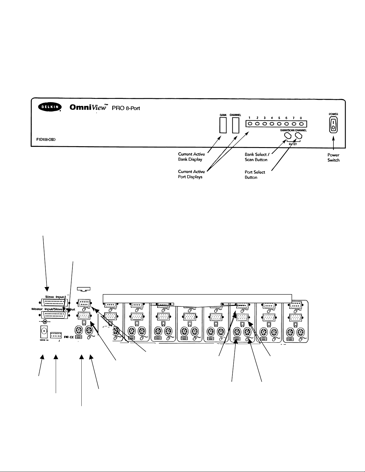
Product Details
FRONT PANEL
REAR PANEL
SLAVEINPUT
DB25 Daisy-chain port
MASTERINPUT
SLAVE OUTPUT
0625 Daisy-chain
port
DC power
jack
DIP switches
CONSOLE
connectors
F-i-
PS/2 mouse
connector
Keyboard
connector
~
VGA monitor
connector
Optional serial
mouse
connector
PC PORT
connectors
Serial mouse
output
Keyboard
Output
VGA signal
Output
PS/2 mouse
output
Page 5

The OmniView- PRO requires cables to connect the eight computers you will be controlling.
Below are the Belkin part numbers and their descriptions. We recommend purchasi ng Cable Kits
based on the type of mouse port your computer uses. Cable kits have all the cables you need to
connect one computer to the OmniView" PRO:
PS/2 Cable Kit - A3X982
Includes:
2 x F2NO36-06
1 x F2NO25-06-T
AT Cable Kit - A3X939
Includes:
1 x F3A510-06
1 x F2NO25-06-T
I x F2N209-06-T
1 x F2NO17
(see below for descriptions of each)
Individual Cables and Adapters:
PS/2 cable for keyboard and mouse ports 6 pin
Mini DIN male/male
Part# F2NO36-XX
Standard VGA cable for monitor port. HDDB15
male/female with thumbscrews
Part# F2NO25-XX-T
Serial extension cable for serial mouse
DB9 male/female with thumbscrews
Part# F2N209-XX-T
6 pin Mini Din
HDDB15
AT keyboard cable for AT-style keyboard port 5 pin
DIN male/male
Part# F3A510-XX
AT to PS/2 keyboard adapter
5 pin DIN female/6 pin Mini DIN male
Part# F2NO17
Other Cables and Adapters-.
11 High-resolution/high -refresh rate VGA cable for monitor port
HDDB15 male/female with thumbscrews
Part# A3H981-XX
PS/2 to AT keyboard ad apter - for use with a computer having an AT-style keyboard port
6 pin Mini DIN female/ 5 pin DIN male 6 pin 5 pin
NOTE: The "-XX" in the part number represents the length in feet.
6
DIN Female DIN Male
Page 6
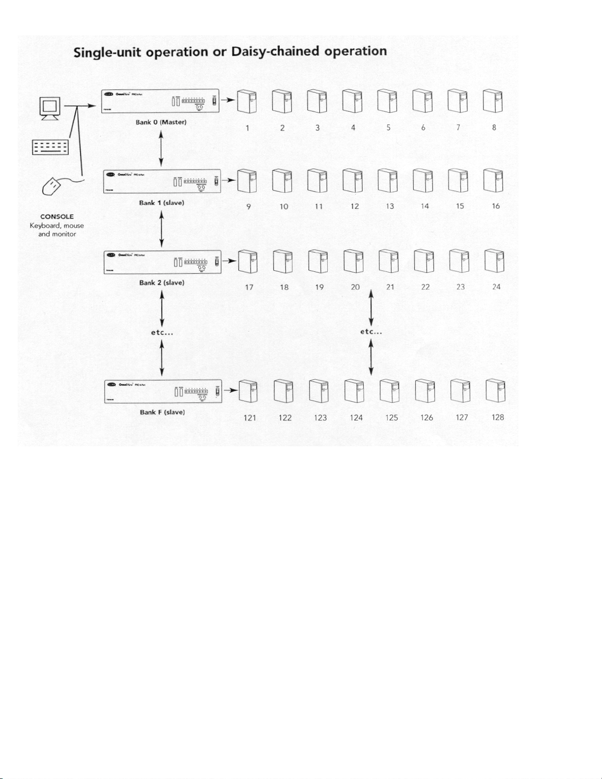
The OrnniView" PRO has the capability to be daisy-chained to 1 5 more units ( for a total of 16),
giving the user control over a maximum of 128 computers!
Each OrnniView" PRO unit is defined as a "BANK." See diagram above for more information.
BANK numbers range from 0 to F (hexadecimal), for a total of 16 BANKS. BANK 0 is the
MASTER bank, while banks 1 through F are slave banks. The MASTER bank is the unit that
connects to the console keyboard, mouse, and monitor.
The DIP switches must be set correctly for proper identification and usage. See the
next section for the actual settings. If you are using the OmniView- PRO in a single- unit
configuration, it must be set as the M ASTER (BANK 0). If it is to be used as a slave unit,
then it must be set to any unused unique ba nk number from I through F.
7
Page 7

Hardware Installation
PLEASE FOLLOW THIS INSTALLATION PROCEDURE EXACTLY. NOT DOING SO MAY
RESULT IN KEYBOARD AND/OR MOUSE ERRORS, OR FAULTY OPERATION.
WARNING: Before attempting to connect any t hing to the OmniView- PRO or the computer make
sure everything is pow ered off. P lugging
to your computers and the OmniView- PRO. B e lkin Co mpone nts will not be held
responsible for damage caused.
. Set the DIP switches. If you have only one OmniView" PRO, use the MASTER bank
1
setting. If the OmniView- PRO you are using will be daisy-chained off another unit, use a
unique slave setting. Please refer to the previous section for more information.
and unplugging cables may cause irreversible damage
NOTE: "
Find a convenient place to put your OmniView- PRO. Its 19" form factor makes it ideal for
2.
19" racks. When mounting to a rack, attach the included brackets to the sides of the
OmniView" PR O. Take note of the length of your cables so that your co mputers, OmniVi ewPRO, keyboard, mouse, and monitor are distanced properly.
ON" is down
Page 8

Installation (continued)
4.Connect the keyboard and mouse to the OmniView- PRO. If you have an AT-style keyboar d,
you will need an AT-PS/2 adapter (Belkin Part# F2NO1 7).
Hardware
Back of OmniViewl" PRO
PS/2 Mouse
,5. Connect the first computer's VGA cable to the OmniView" PRO. Using the VGA cable (Belkin
Part# F2NO25-XX-T or A3H981-XX), connect the male end of the cable to the VGA port on
the computer, and the female end on the PC1 VGA port at the back of OmniView- PRO.
F2NO25-XX-
9
Page 9

Hardware Installation (continued)
Connect the first computer's mouse cable to the OmniView- PRO. If using a PS/2 cable
6.
(Belkin Part# F2NO36-XX), connect one end to the PS/2 mouse port on the computer, and
the other end to the PC1 PS/2 mouse port on the back of the OmniView". If using a serial
mouse cable (Belkin Part# F2N209-XX-T), connect one end to a DB9 serial port on the
computer, and the other end to the PC1 DB9 serial mouse port on the back of the OmniViewPRO.
7.
Connect the first computer's keyboard cable to the OmniCube". Using another
PS/2 cable (Belkin Part# F2NO36-XX), connect one end to the PS/2 keyboard
port on the computer, and the other end to the PC1 keyboard port on the back
of the OmniCube-. If your computer has an AT-style keyboard port, you will
need a PS/2-AT keyboard adapter (Belkin Part# F2NO18).
8. Double check all of the connections. Make sure the keyboard and mouse cables go to
the correct ports.
9. Repeat steps 5-7 for the remainder of the computers.
1 0. Attach the power supply to the power supply connector at the back of the OmniView"
PRO. Plug this into any available AC outlet. Flip the power switch on the front of the
OmniView- PRO. You should see the LED for Port 1 on the front panel blink, and hear a
beep. Power up your mo nit or .
11
. You can now power up all your computers simultaneously. The first computer will show up
on the monitor. Check to see if the keyboard and mouse works, as well as the image
displayed on the screen. If this is okay, press the SELECT button and check the
functionality of the other computers. If you find any errors, double-check all of the cable
connections.
10
Page 10

Hardware Installation (continued)
NOTE: Avoid pressing any keys on the keyboard or moving the mouse if the currently selected
port has a computer that is in the process of booting up. This may cause the computer to not
detect, or initialize the keyboard or mouse drivers properly.
Daisy-Chaining the OmniVieW" PRO:
The OmniView- PRO can be daisy-chained with additional OmniView PRO units through the
DB25 daisy-chain ports. The Fl Dl 08-CBL daisv-chain cable is required (not included) for proper
operation. Please refer to the example below. Here, four OmniView PRO units are cascaded
together for control over 32 computers. Recall that a maximum of 16 OmniView PRO units can be
cascaded together for control over 128 computers. Recall that the DIP switches on the MASTER
unit must be set to BANK 0, and the slave units set to a unique BANK (any from 1 through F).
See the beginning of this section for more information on the DIP switch settings.
Cable 1
MASTER
(Bank 0)
Cable 2
Cable 3
slave
(Bank 1)
slave
(Bank 2)
slave
(Bank3)
- After setting the DIP switches on the slave unit, connect the computers using the same
procedure outlined in steps 5 to 9 in the previous section. DO NOT POWER UP THE
COMPUTERS YET.
Using the Fl Dl 08-CBL daisy-chain cable, connect one end to the 'Master Input/ Slave
Output' of the unit. Refer to the diagram above.
If the previous unit is the MASTER, then the other end of the cable connects to the
"Master Input/Slave Output" port of the MASTER (such as cable 1 in t he diagram
above).
- If the previous unit is a slave, then the other end goes to the 'Slave Input' port of the
previous slave unit (such as cables 2 and 3 in the diagram above).
11
Page 11

Hardware Installation (continued)
Upon connecting the daisy-chain cable to the previous unit, it should automatically
power up if the previous unit is powered up. However, it is still recommended that the
power supply be used with the slave unit. You will see the LEI) display on the front
panel show the units bank address setting.
RESET the MASTER unit by pressing the BANK/SCAN and CHANNEL buttons
simultaneously. This is necessary for the MASTER unit to detect the newly added slave
unit.
Verify that the MASTER unit has detected the new slave by pressing the BANK/SCAN
button. If it detected the new slave properly, the LED display on the M ASTER will register
the slave units bank address. If you have many slave units, you may have to press the
BANK/SCAN button many times to cycle through all of the preexisting slave units before
reaching the newly added unit.
Now you can power up the computers connected to the newly added slave unit. After
all the computers have booted up, you may need to RESET the MASTER unit again
to detect the presence of powered computers on the new slave unit.
NOTE:
(FlDlO2andFlDlO4only). This gives the user more selection and flexibility. When doing this, it
is desirable to have the OmniView- PRO as the MASTER unit because of the On-Screen Display
(OSD) menu feature. Thus, all the units will benefit from the OSD control, even if the
OrnniView SE" does not have the OSD feature.
The OmniView- PRO can also be daisy-chained to OmniView SE- units
Page 12

Usage
Selecting which computer to operate can be done either by On-Screen Display, the
SELECT button, or through keyboard hot-key commands. You will notice that after the
OmniView- PRO switches to another computer, the mouse will be inoperative for about
1-2 seconds. This is normal operation and ensures that proper mouse synchronization
is established.
The SELECT Button-.
Pressing the SELECT button cycles you t hrough
the ports, including inactive ports
all
You can switch directly to any port by giving the OmniView- PRO the BANK and PORT
numbers. For instance, if you press [SCROLL LOCK] [SCROLL LOCK] 121 [51, the computer
on PORT 5 of the OmniView- PRO set to BANK 2 will be selected. In the following diagram,
that is PC # 21. Hence, if you only have one OmniView- PRO, the first key (X) must be "O".
13
Page 13

In AutoScan mode, the OmniView- PRO remains on one port for a number of seconds, before
switching to the next. This time interval is set in the On-Screen Display menu.
NOTE: There is no mouse or keyboard control in this mode. This is necessary
to prevent errors. Otherwise, if the user is moving the mouse or using the keyboard when the
OmniView- PRO switches to the next port, data flow is interrupted and will cause erratic
mouse movement and/o r the wrong
characters to show up when using the keyboard.
To get out of AutoScan mode, press the SPACEBAR.
14
Page 14

Usage (continued)
On-Screen Display Menu Control:
To get into the On-Screen Display (OSD) menu, pr ess [SCROLL LOCK] [SCROLL LOCK]
[SPACEBAR]. Immediately, the OSD overlay screen appears. This screen is generated by the
OmniView- PRO, and does not affect yo ur computers or running software in an y way.
The main OSD screen
menu is shown on the
right. It shows the
currently selected BANK.
If you have
only one OmniViewPRO, it will say "BANK
oll.
The current selected port
is shown in RED.
A " # " indicates that the
computer connected to
that port is powered up.
Enable the On-Screen Display Menu
* You can navigate through the active ports by using the arrow keys. The OS[) menu will only
allow you to move to active ports.
NOTE: If a computer is connected and is powered up, but the OSD menu does not
display a '*", you will have to RESET the
computers. This is done by simultaneously pressing the BANK/SCAN and
CHANNEL buttons on the front panel.
- Pressing the [INSERT] key allows you to rename t he port. Press (ENTER] to complete
- Pressing the [ESCI key exits the current screen
To view a different BANK, pressing the [PAGE UP] key goes to a previous BANK, while
the (PAGE DOWN] key brings you to the next BANK.
,* Once you have selected a computer on the menu, press JENTER] to switch to that port
- Pressing the [TAB] key opens up the Function menu. In this menu, you can select the SCAN
TIME and the DISPLAY TIME.
OmniVieWTM
is
PRO to re- detect the powered
Page 15

Usage (continued)
SCAN TIME:
Amount of time the OmniView- PRO stays on
one port before switching to the next port when
in Scan Mode.
DISPLAY TIME:
Amount of time the OSD Menu or Port Name
remains displayed on-screen after making a
port selection.
Note: If there are slave units present, the SCAN TIME and DISPLAY TI ME settings are set
on the MASTER unit only, and need not be set on the slave units.
The BANK / SCAN Button:
Pressing the BANK / SCAN button cycles you through all the active BANKs (if there
slave units present) and then puts the unit in AutoScan mode. If the unit is a si ngle
MASTER unit, pressing the b utton immediat ely invokes AutoScan mode. This is
evident by a long BEEP, followed by two short beeps.
16
Page 16

Trouble Shooting
General Problems:
Q: The OSD menu does not display a "#" on a port where a computer is connected and
powered up. What do I do?
RESET the OmniView- PRO by simultaneously pressing the BANK/SCAN and
A:
CHANNEL buttons on the front panel. Access the OSD menu again and it should have
re-detected all the active ports.
Q: When cascading, the MASTER unit does not see the slave unit(s).
Refer to the Hardware Installation section for information on how to properly connect
A: -
the daisy-chain cable.
- Make sure that the daisy-chain cable that you are using is the Fl DI 08-CBL. Using
any other cable will not guarantee proper operation or video quality.
RESET the MASTER OmniView PRO.
- Although a power supply is not necessary to make the slave unit work, try adding a
power supply.
Monitor/Video Problems:
Q. I am getting ghosting, shadowing or fuzzy images on my monitor. What do I do? A: -
Check the cables and make sure they are inserted properly.
• Your resolution and/or refresh rate is extremely high, or your cable is too long. Replace your
VGA cables with coaxial, double-shielded cables such as Belkin A3H981-XX.
• Check to make sure that the power adapter is plugged in and is working properly. It must be
12VDC, I OOOMA minimum. Make sure the power switch is on.
• Lower you refresh rate andfor screen resolution settings.
Keyboard Problems.
Q: The keyboard is not detected, or a keyboard error is reported during boot-up.
Check the cables and make sure they are inserted properly in the correct
A: -
ports.
• Check to make sure that the power adapter is plugged in and is working properly. It must be
12VDC, 1 OOOMA minimum. Make sure the power switch is on.
• RESET the OmniView- PRO by simultaneously pressing the BANK/SCAN and CHANNEL
buttons on the front panel. Access the OSD menu again and it should have re-detected all the
active ports.
• Do not press any keys on the keyboard whil e the selected computer is b ooting up. This is true
for any PC, whether stand-alone or connected to a KVM switch.
Q: The computers boot up fine, but the keyboard does not work.
Check the cables and make sure they are inserted properly in the correct ports.
A: -
• Make sure the keyboard works when directly plugged into the computers.
• Try a different keyboard, but use only 101, 102 or 104-key keyboards.
• Make sure that the keyboard driver is for 101, 102 or 104-key keyboards, and not old XT
keyboards.
• Check to make sure that the power adapter is plugged in and is working properly. It must be
12VDC, 1 OOOMA minimum. Make sure the power switch is on.
• RESET the OmniView- PRO by simultaneously pressing the BANK/SCAN and CHANNEL
buttons on the front panel. Access the OSD menu again and it
should have re-detected all the active ports.
17
Page 17

Trouble Shooting (continued)
PS/2 Mouse Problems at the console or computers:
Q: The mouse is not detected during boo t -up.
Check the cables and make sure they are inserted properly in the correct ports.
A:
•Check your computer/mo therboard documentation making sur e that the PS/2
mouse port (or IRQ) is enabled.
•Make sure the mouse is detected directly plugged into the computer. Rebooting is necessary
when trying this. If the computer still does not detect the mouse, then your computer's PS/2
mouse port has a problem.
•RESET the OmniView- PRO by simultaneously pressi ng the BANK/SCAN and CHANNEL
buttons on the front panel. Access the OSD menu again and it should have re-detected all
the active ports.
Q: The computers boot up fine, but the mouse does not work.
A: Check the cables and make sure they are inserted properly in the correct ports.
• Make sure the mouse works when directly plugged into the computer. Rebooting is
necessary when trying this. If the mouse pointer still does not move, then either your PS/2
mouse port or the mouse itself has a problem.
• Try a different mouse.
• Make sure the mouse is a true PS/2 mouse. A combo mouse will work just as long as it is set
for PS/2 mode with the correct adapter. A serial-only mouse with a combo mouse adapter
WILL NOT work.
• Check to make sure that the power adapter is plugged in and is working properly. It must be
12VDC, 10OOrnA mini mum. Make sure the power switch is on.
• RESET the OmniView- PRO by simultaneously pressing the B ANK/SCAN and CHANNEL
buttons on the front panel. Access the OSD menu again and it
should have re-detected all the active ports.
a
@
t
.
@
Q: When I switch fr om
I do?
RESET the OmniView- PRO by simultaneously pressing the BANK/SCAN and CHANNEL
A:
buttons on the front panel. Access the OSD menu again and it
should have re-detected all the active ports.
• Make sure you do not have more than one mouse driver. Make sure that the driver is either
for a Standard PS/2 or Microsoft'-compatible PS/2 mouse. Try to obtain the latest version
from your hard wa re manu fa ct u re r .
• If you are using a specialized mouse such as a cordless mouse, scrolling mouse or mice with
more than 2 operational buttons, use generic PS/2 mouse drivers. Non-standard mice often
use non-PS/2 proprietary mouse protocol.
• Make sure you do not have any mouse drivers loaded in your config.sys or autoexec.bat files.
• Avoid moving the mouse or pressing the mouse buttons when switching ports. Reset the
mouse to resume proper mouse movement simply by unplugging the mouse from the front of
the OmniView- PRO for about 2-3 seconds, and
plugging it in again.
one
port to another, mouse movement is completely erratic. What do
Problems with computers using the serial mouse output:
The OmniView- PRO has Integrated Mouse Conversion Technology. This technology
Note:
converts the PS/2 mouse signals at the console to serial mouse signals. Windows' 9x Control
Panel System applet may not display that it has detected a mouse, but the Modem applet will
show a serial mouse at a certain serial port.
Q: The computers boot up fine, but the mouse does not work.
Check the cables and make sure they are inserted properly in the correct ports. - Check the
A: -
cable and make sure that it is a straight-through DB9 rnale/female
18
Page 18

Trouble Shooting (continued)
cable such as Belkin P/N F2N209-XX-T (XX is the length in feet).
• Check your computer/mother-board documentation making sure that the serial ports are
enabled, and that there are no IRQ or base address conflicts with other serial ports or
modems.
• Plug in a serial mouse directly to your computer, and reboot. If the mouse pointer still does
not move, then there may be no serial mouse drivers installed, or the serial port on your
computer may have other conflicts or problems.
• Try a different PS/2 mouse at the console.
• Make sure the mouse (at the console) is a true PS/2 mouse. A combo mouse will work just
as long as it is set for PS/2 rnode with the correct adapter. A serial-only mouse with a combo
mouse adapter WILL NOT work.
• Check to make sure that the power adapter is plugged in and is working property. It must be
12VDC, 1 OOOMA minimum. Make sure the power switch is on.
• RESET the OmniView- PRO by simultaneously pressing the BANK/SCAN and CHANNEL
buttons on the front panel. Access the OSD rnenu again and it
should have re-detected all the active ports.
Q: When I switch from one port to another, mouse movement is completely erratic. What
de I do?
A: - RESET the OmniView- PRO by simultaneously pressing the BANK/SCAN and CHANNEL
buttons on the front panel. Access the OSD menu again and it should have re-detected all
the active ports.
•Make sure you do not have more than one serial mouse driver loaded. Make sure that the
driver is either for a Standard Serial or Microsoft"-compatible serial mouse.
•Avoid using a specialized mouse at the console such as a cordless mouse, scrolling mouse or
mice with more than 2 operational buttons. Non-standard mice often use non-PS/2
proprietary mouse protocol.
•Make sure you do not have a ny other mouse drivers loaded in your config.sys or
autoexec.bat files.
•Avoid moving the mouse or pressing the mouse buttons when switching ports. •Reset the
mouse to resume proper mouse moveme nt simply by unplugging the
mouse fro m t h e OrnniView- PRO for about 2-3 seconds, and plugging it in again.
Q: The wheel on the lntellimouse" does not work on my computer. Why?
A: - The Integrated Mouse Conversion Technology converts only the standard PS/2 signals which
are the buttons and the x and y coordinate movement, but not the wheel movement or wheel
button. This is because the wheel and wheel button data use non-PS/2 protocol.
Note about the Optional Serial Mouse port at the console: If you have tried all possible
troubleshooting methods, you can plug in a serial mouse (as a second mouse) at the optional serial
mouse input port. See the Product Detail Section for the diagram. This mouse will be dir ectly
connected to the serial mouse ports on the OmniView- PRO. Note that the serial mouse signals
will not be converted to PS / 2 mouse signal s, so if you have other PCs using PS/2 mouse ports, you
must keep the PS/2 mouse at the console. This serial mouse is a second mouse, and is active only
when on a computer that uses the serial mouse output.
19
Page 19

Information
Contacting Belkin Components
Corporate Headquarters Belkin Components, Ltd.
501 West Walnut Street Clarke Road
Compton o CA - 90220 Mount Farm * Bletchley
Phone 310.898.1 1 00 Milton Keynes * MK1 1 LG
800.223.5546 United Kingdom
Fax 310.898.1111 Phone +44 (0) 1908367178
Fax +44 (0) 1908366564
www.belkin.com
FCC Statement
This equipment has been tested and found to comply with the limits for a Class B digital device, pursuant to part 15 of the
FCC Rules. These limits are designed to provide reasonable protection against harmful interference in a residential
installation. This equipment generates, uses and can radiate radio frequency energy and, if not installed and used in
accordance with the instructions, may cause harmful interference to radio communications. However, there is no guarantee
that interference will not occur in a particular installation. If this equipment does cause harmful interference to radio or
television reception, which can be determined by turning the equipment off and on the user is encouraged to try to correct
the interference by one or more of the following measures:
• Reorient or relocate the receiving antenna-
• Increase sepa r ation between t he equipment and receiver.
• Connect the equipment into an outlet on a circuit different from that to which
the receiver is connected.
• Consult the dealer or an experienced radio technician for help.
CE Declaration of Conformity
We, Belkin Components, declare under our sole responsibility that the Fl Dl 08-OSD, to which this declaration relates,
is in conformity with Generic Emissions Stand ard EN50081 -1 and with Generic Immunity Standard EN50082-1 1992.
Belkin Components One Year Product Warranty
Belkin Components warrants this product against defects in materials and workmanship for one year. If a defect is
discovered, Belkin will, at its option, repair or replac e the product at no charge p r ovided it is returned during the warranty
period, with transportation charges prepaid, to the authorized Belkin dealer
from whom you purchased the product. Proof of purchase may be required.
This warranty does not apply if the product has been damaged by accident, abuse, misuse, or misapplication; if the product
has been modified without the written permission of Belkin; or if any Belkin serial number has been removed or defaced.
THE WARRANTY AND REMEDIES SET FORTH ABOVE ARE EXCLUSIVE IN LIEU OF ALL OTHER S,
WHETHER ORAL OR WRITTEN, EXF>RESSED OR IMPLIED. BELKIN SPECIFICALLY DISCLAIMS ANY AND
ALL IMPUED WARRANTIES, INCLUDING, WITHOUT LIMITATION, WARRANTIES OF MERCHANTABIUTY
AND FITNESS FOR A PARTICULAR PURPOSE.
No Belkin dealer, agent, or emp loyee is authorized to make any modification, extension, or
addition to this warranty.
BELKIN IS NOT RESPONSIBLE FOR SPECIAL, INCIDENTAL, OR CONSEQUENTIAL DAMAGES RESULTING
FROM ANY BREACH OF WARRANTY, OR UNDER ANY OTHER LEGAL THEORY, INCLUDING BUT NO T LIMITED TO LOST PROFITS, DOWNTIME, GOODWILL, DAMAGE TO OR REPROGRAMMING, OR REPR ODUCING ANY PROGRAM OR DATA STORED IN OR USED WITH BELKIN PRODUCTS.
Some states do not allow the exclusion or limitation of incidental or consequential damages or exclusions of implied
warranties, so the above limitations of exclusions may not apply to you. This warranty gives you specific legal rights, and
you may also have oth er rights that vary from state to s tate.
20
 Loading...