

Page 1

F5D9630uk4A
User Manual
Network your
computers and
share your ADSL
Internet access
ADSL2+ Modem
with Wireless
G+ MIMO Router
UK
FR
DE
NL
ES
IT
Page 2

Table of Contents
1
1 Introduction . . . . . . . . . . . . . . . . . . . . . . . . . . . . . . . . . . . . . . . . . . . . . . 1
Benefits of a Home Network . . . . . . . . . . . . . . . . . . . . . . . . . . . . . . . .
Advantages of a Belkin Wireless Network. . . . . . . . . . . . . . . . . . . . . .
2 Make Sure You Have the Following. . . . . . . . . . . . . . . . . . . . . . . . . . . . .
Package Contents . . . . . . . . . . . . . . . . . . . . . . . . . . . . . . . . . . . . . . . .
System Requirements . . . . . . . . . . . . . . . . . . . . . . . . . . . . . . . . . . . . .
Internet Connection Settings. . . . . . . . . . . . . . . . . . . . . . . . . . . . . . . .
3 Knowing your Router . . . . . . . . . . . . . . . . . . . . . . . . . . . . . . . . . . . . . . .
4 Connecting your Router . . . . . . . . . . . . . . . . . . . . . . . . . . . . . . . . . . . . .
Positioning your Router. . . . . . . . . . . . . . . . . . . . . . . . . . . . . . . . . . . .
Connecting your Computers . . . . . . . . . . . . . . . . . . . . . . . . . . . . . . . .
Connecting your ADSL Line . . . . . . . . . . . . . . . . . . . . . . . . . . . . . . . .
Powering Up your Router . . . . . . . . . . . . . . . . . . . . . . . . . . . . . . . . . 10
5 Setting Up your Computers . . . . . . . . . . . . . . . . . . . . . . . . . . . . . . . . .
Manually Configuring Network Adapters . . . . . . . . . . . . . . . . . . . . . . 11
Recommended Web Browser Settings . . . . . . . . . . . . . . . . . . . . . . . 17
6 Configuring your Router with the Setup Wizard . . . . . . . . . . . . . . . . . 19
Running the Setup Wizard . . . . . . . . . . . . . . . . . . . . . . . . . . . . . . . . 19
7 Manually Configuring Your Router . . . . . . . . . . . . . . . . . . . . . . . . . . . .
Understanding the Web-Based User Interface . . . . . . . . . . . . . . . . .
Changing LAN Settings . . . . . . . . . . . . . . . . . . . . . . . . . . . . . . . . . . . 25
DHCP Client List . . . . . . . . . . . . . . . . . . . . . . . . . . . . . . . . . . . . . . . .
Internet WAN. . . . . . . . . . . . . . . . . . . . . . . . . . . . . . . . . . . . . . . . . . . 28
Setting your ISP Connection Type to PPPoE or PPPoA . . . . . . . . . . 30
Wireless. . . . . . . . . . . . . . . . . . . . . . . . . . . . . . . . . . . . . . . . . . . . . . .
Encryption/Security. . . . . . . . . . . . . . . . . . . . . . . . . . . . . . . . . . . . . . 37
WEP Setup . . . . . . . . . . . . . . . . . . . . . . . . . . . . . . . . . . . . . . . . . . . . 41
WAP Setup . . . . . . . . . . . . . . . . . . . . . . . . . . . . . . . . . . . . . . . . . . . . 42
Configuring your Computer’s Network Adapter to Use Security. . . . 46
Wireless Bridge . . . . . . . . . . . . . . . . . . . . . . . . . . . . . . . . . . . . . . . . . 51
Firewall . . . . . . . . . . . . . . . . . . . . . . . . . . . . . . . . . . . . . . . . . . . . . . . 52
Utilities . . . . . . . . . . . . . . . . . . . . . . . . . . . . . . . . . . . . . . . . . . . . . . .
8 Troubleshooting . . . . . . . . . . . . . . . . . . . . . . . . . . . . . . . . . . . . . . . . . .
9 Appendixes . . . . . . . . . . . . . . . . . . . . . . . . . . . . . . . . . . . . . . . . . . . . . . 76
Appendix A: Glossary . . . . . . . . . . . . . . . . . . . . . . . . . . . . . . . . . . . .
Appendix B: Important Factors for Placement and Setup. . . . . . . . . 83
Appendix C: Internet Connection Setting Table . . . . . . . . . . . . . . . . 85
10 Information . . . . . . . . . . . . . . . . . . . . . . . . . . . . . . . . . . . . . . . . . . . . . 87
11
23
23
28
35
56
64
77
1
1
2
2
2
2
3
6
6
7
8
Page 3

1
Introduction
Thank you for purchasing the Belkin ADSL Modem with High-Speed
Mode Wireless G Router (the Router). In minutes you will be able to
share your Internet connection and network your computers with your
new Router. The following is a list of features that make your Router
an ideal solution for your home or small office network. Please be sure
to read through this User Manual completely, and pay special attention
to Appendix B entitled “Important Factors for Placement and Setup”.
section
1
2
3
Benefits of a Home Network
By following our simple setup instructions, you will be able to use
your Belkin home network to:
• Share one high-speed Internet connection with all the computers
in your home
• Share resources, such as files, and hard drives among all the
connected computers in your home
• Share a single printer with the entire family
• Share documents, music, video, and digital pictures
• Store, retrieve, and copy files from one computer to another
• Simultaneously play games online, check Internet email,
and chat
Advantages of a Belkin Wireless Network
Mobility – you’ll no longer need a dedicated “computer room”— now you
can work on a networked laptop or desktop computer anywhere within
your wireless range
Easy installation –
Flexibility – set up and access printers, computers, and other
networking devices from anywhere in your home
Easy Expansion – the wide range of Belkin networking products let
you expand your network to include devices such as printers and
gaming consoles
No cabling required – you can spare the expense and hassle of
retrofitting Ethernet cabling throughout the home or office
Widespread industry acceptance – choose from a wide range of
interoperable networking products
Belkin’s Easy Installation Wizard makes setup simple
4
5
6
7
8
9
10
12
1
Page 4

32
Make Sure You Have the Following
Package Contents
• ADSL2+ Modem with Wireless G+ MIMO Router
• RJ11 Telephone Cord - Gray
• RJ45 Ethernet Networking Cable - Yellow
• ADSL Microfilter*
• Power Adapter
• User Manual CD
*ADSL microfilter varies by country. If it’s not included, you will need to purchase
one.
System Requirements
• An active ADSL service with a telephone wall jack for connecting
the Router
• At least one computer with a Network Interface Card (NIC) and Internet
browser installed and correctly configured
• TCP/IP networking protocol installed on each computer connected to
the Router
• No other DHCP server on your local network assigning IP addresses to
computers and devices
Internet Connection Settings
Please collect the following information from your Internet Service Provider (ISP)
before setting up the ADSL Modem Wireless G Router.
• Internet connection protocol: _________ (PPPoE, PPPoA, Dynamic IP, Static IP)
• Multiplexing method or Encapsulation: __________ (LLC or VC MUX)
• Virtual circuit: VPI (Virtual Path Identifier) __________
(a number between 0 and 255)
• VCI (Virtual Channel Identifier) __________
(a number between 1 and 65535)
• For PPPoE and PPPoA users: ADSL account user name _____________ and
password _______________
• For static IP users: IP Address ___ . ___ . ___ . ___
Subnet Mask ___ . ___ . ___ . ___
Default Gateway Server ___ . ___ . ___ .
• IP address for Domain Name Server ___ . ___ . ___ . ___ (If given by your ISP)
Note: See Appendix C in this User Manual for some common DSL Internet
setting parameters. If you are not sure, please contact your ISP.
Page 5
3
Knowing your Router
The Router is designed to be placed on a desktop. All of the cables exit from
the rear of the Router for better organization and utility. The LED indicators
are easily visible on the front of the Router to provide you with information
about network activity and status.
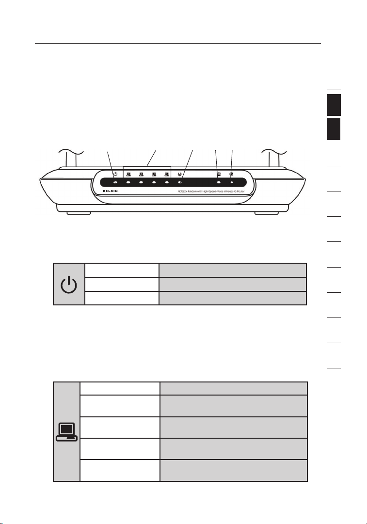
Front Panel
(1) (4) (3)(5)(2)
1. Power LED
When you apply power to the Router or restart it, a short period of time
elapses while the Router boots up. When the Router has completely
booted up, the Power LED becomes a GREEN light, indicating the
Router is ready for use.
2. LAN Status LEDs
These LAN Status LEDs are labeled 1–4 and correspond to the
numbered ports on the rear of the Router. When a computer is properly
connected to one of the LAN ports on the rear of the Router, the LED
will light. Solid GREEN means a computer or a network-enabled device
is connected. When information is being sent over the port, the LED
blinks rapidly. ORANGE indicates a 10Base-T connection.
OFF Router is OFF
Green Router is ON
Red Router failed to start
OFF No device is connected
Orange Ethernet link is up and 10Base-T
device connected
Orange - blinking When 10Base-T device transmitting
or receiving data
Green Ethernet link is up and 100Base-T
connected
Green - blinking When 100Base-T device
transmitting or receiving data
1
2
section
3
4
5
6
7
8
9
10
11
12
3
Page 6
Knowing your Router
54
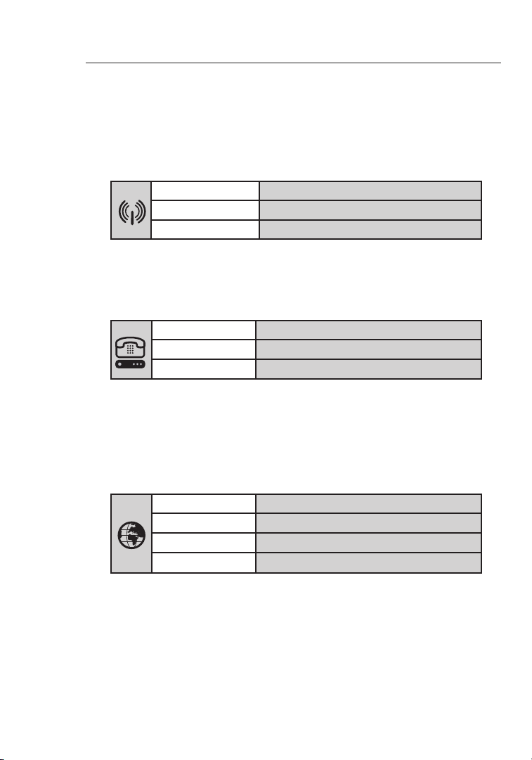
3. WLAN Status LED
The WLAN Status LED is solid GREEN when you enable the
wireless LAN function. It flashes when the Router is transmitting
or receiving data wirelessly.
OFF WLAN is off
Green WLAN is up and connected
Green - blinking When transmitting or receiving data
4. ADSL LED
The ADSL LED flashes GREEN during negotiation with your ISP.
It stays GREEN when the Router is connected properly to your
ADSL service.
OFF No ADSL connection
Green ADSL link is up and connected
Green -
5. Internet LED
The Internet LED shows you when the Router is connected to
the Internet. When the LED is OFF, the Router is NOT connected
to the Internet. When the LED is solid GREEN, the Router is
connected to the Internet. When the LED is blinking, the Router
is transmitting or receiving data from the Internet.
blinking negotiating connection
OFF No Internet connection
Green Connected to the Internet
Green Red Failed to get IP
blinking When transmitting or receiving data
Page 7
5
Knowing your Router
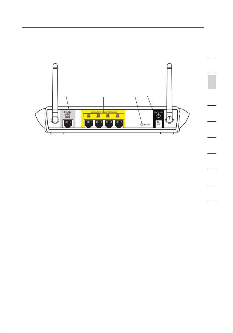
Back Panel
(6)
6. DSL Line
This port is for connection to your ADSL line. Connect your ADSL
line to this port.
7. Ethernet Ports
The Ethernet ports are RJ45, 10/100 auto-negotiation. The ports
are labeled 1 through 4. These ports correspond to the numbered
LEDs on the front of the Router. Connect your network-enabled
computers or any networking devices to one of these ports.
8. Reset Button
The “Reset” button is used in rare cases when the Router
may function improperly. Resetting the Router will restore the
Router’s normal operation while maintaining the programmed
settings. You can also restore the factory default settings by
using the Reset button. Use the restore option in instances where
you may have forgotten your custom password.
a. Resetting the Router
b. Restoring the Factory Defaults
9. Power Plug
Connect the included 15V DC power supply to this inlet. Using
the wrong type of power adapter may cause damage to your
Router.
Push and hold the Reset button for one second then release
it. When the Power/Ready light becomes solid again, the
reset is complete.
Press and hold the Reset button for five seconds then
release it. When the Power/Ready light becomes solid again,
the restore is complete.
(7) (8) (9)
1
2
section
3
4
5
6
7
8
9
10
12
5
Page 8

Connecting your Router
76
Positioning your Router
Your wireless connection will be stronger the closer your computer
is to your Router. Typical indoor operating range for your wireless
devices is between 100 and 200 feet. In the same way, your wireless
connection and performance will degrade somewhat as the distance
between your Router connected devices increases. This may or may
not be noticeable to you. As you move farther from your Router,
connection speed may decrease. Factors that can weaken signals
simply by getting in the way of your network’s radio waves are metal
appliances, or obstructions, and walls. Please see “Appendix B:
Important Factors for Placement and Setup” in this User Manual for
more guidelines.
If you have concerns about your network’s performance that might be
related to range or obstruction factors, try moving the computer to
a position between five and 10 feet from the Router, in order to see
if distance is the problem. If difficulties persist even at close range,
please see the Troubleshooting section for solutions.
Page 9
7
Connecting your Router
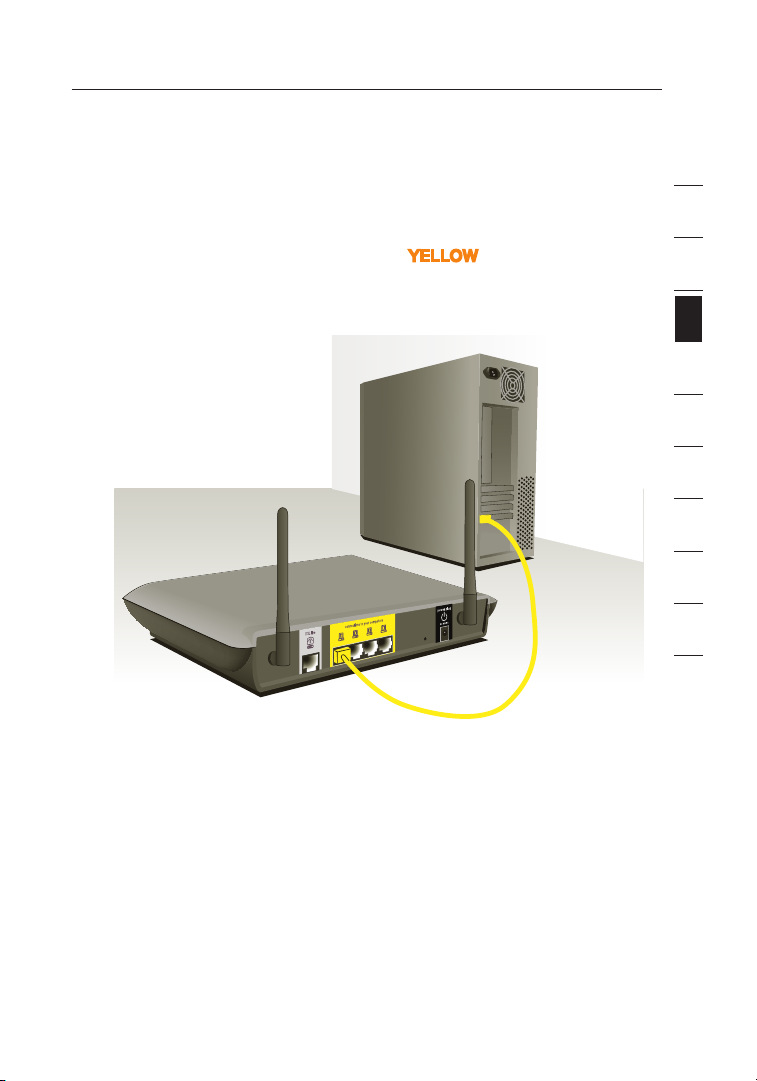
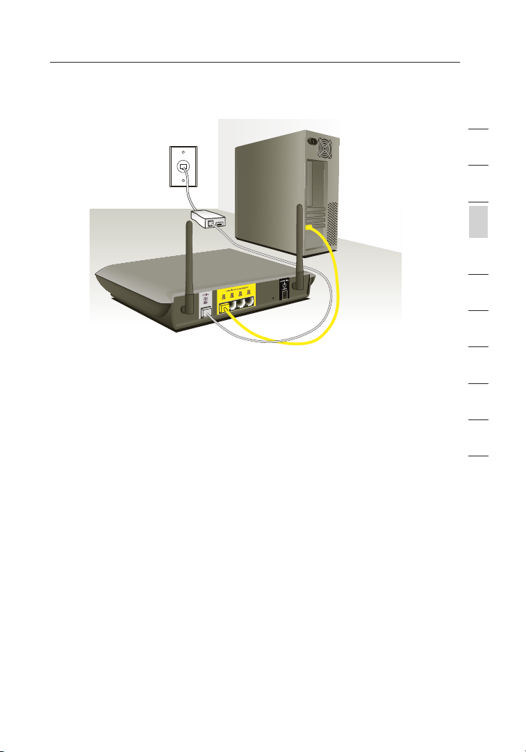
Connecting your Computers
1. Power off your computers and networking equipment.
2. Connect your computer to one of the YELLOW RJ45 ports on the
rear of the Router labeled “connections to your computers” by
using an Ethernet networking cable (one Ethernet network cable
is supplied).
1
2
3
section
4
5
6
7
8
9
10
12
7
Page 10

Connecting your Router
98
Connecting your ADSL Line
Connection for the Router to the ADSL line varies by country and
region. Typically it involves a microfilter or a microfilter with builtin splitter to allow simultaneous use of ADSL service and telephone
service on the same telephone line. Please read the following steps
carefully and select appropriate method.
1. If your telephone service and ADSL service are on the same
telephone line, ADSL microfilters are needed for each telephone
and device, such as answering machine, fax machine, and caller
ID display. Additional splitters may be used to separate telephone
lines for telephone and the Router.
Note: Do not connect the ADSL microfilter between the wall jack
and the Router—this will prevent ADSL service from reaching
the modem.
2. If your telephone service and ADSL service are on the same
telephone line and you are using an ADSL microfilter with built-in
splitter, connect the splitter to the telephone wall jack providing
ADSL service. Then, connect the telephone cord from the ADSL
microfilter RJ11 port generally labeled “DSL” to the gray RJ11
port labeled “DSL line” on the back of your Router. Connect
telephony device to the other port on the ADSL splitter commonly
labeled “Phone”. An additional ADSL microfilter is needed for
another telephone and device on the same line.
Page 11
9
Connecting your Router
Note: One RJ11 telephone cord is supplied. When inserting an
RJ11 plug, be sure the tab on the plug clicks into position to
ensure that it is properly seated.
1
2
3
section
4
5
6
7
8
9
3. If you have a dedicated ADSL service telephone line with an RJ11
wall jack, simply connect a telephone cord from the wall jack to
the gray RJ11 port labeled “DSL line” on the back of
your Router.
4. If you have an RJ45 wall jack for your ADSL service, connect an
RJ45-to-RJ11 converter to the wall jack. Then connect one end of
a telephone cord to the converter and the other end to the gray
RJ11 port labeled “DSL line” on the back of your Router.
Note: ADSL microfilter may or may not be provided depending on
your country.
9
10
12
Page 12
1110
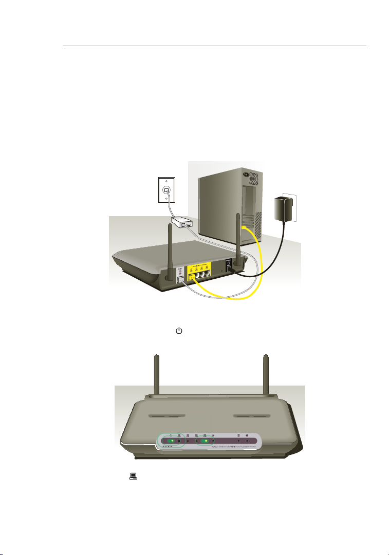
Powering Up your Router
1. Connect the supplied power adapter to the Router power-input
plug labeled “Power”.
Note: For safety and performance reasons, only use the supplied
power adapter to prevent damage to the Router.
2. After connecting the power adapter and the power source is turned on,
the Router’s power icon.
on the front panel should be on. It might
take a few minutes for the Router to fully start up.
3. Turn on your computers. After your computers boot up, the LAN
status LED on the front of the Router will be on for each port
to which a wired computer is connected. These lights show
you the connection and activity status. Now you are ready to
configure the Router for ADSL connection.
Connecting your Router
Page 13
11
Setting Up your Computers
In order for your computer to properly communicate with your Router, you
will need to change your computer’s “TCP/IP Ethernet” settings to “Obtain
an IP address automatically/Using DHCP”. This is normally the default
setting in most home computers.
You can set up the computer that is connected to the ADSL modem
FIRST using these steps. You can also use these steps to add computers
to your Router after the Router has been set up to connect to the Internet.
Manually Configuring Network Adapters in Windows XP, 2000, or NT
1.
Click “Start”, “Settings”, then “Control Panel”.
2. Double-click on the “Network and dial-up connections” icon
(Windows 2000) or the “Network” icon (Windows XP).
3. Right-click on the “Local Area Connection” associated with your
network adapter and select “Properties” from the drop-down menu.
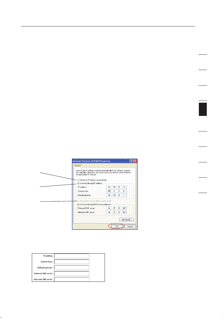
4. In the “Local Area Connection Properties” window, click “Internet
Protocol (TCP/IP)” and click the “Properties” button. The following
screen will appear:
(1)
(2)
(3)
1
2
3
4
section
5
6
7
8
9
10
12
5. If “Use the following IP address” (2) is selected, your Router will need to
be set up for a static IP connection type. Write the address information
the table below. You will need to enter this information into the Router.
6. If not already selected, select “Obtain an IP address automatically”
(1) and “Obtain DNS server address automatically” (3). Click “OK”.
Your network adapter(s) are now configured for use with the Router.
11
Page 14
Setting Up your Computers
1312
Manually Configuring Network Adapters in Windows 98SE or Me
1. Right-click on “My Network Neighborhood” and select “Properties” from
the drop-down menu.
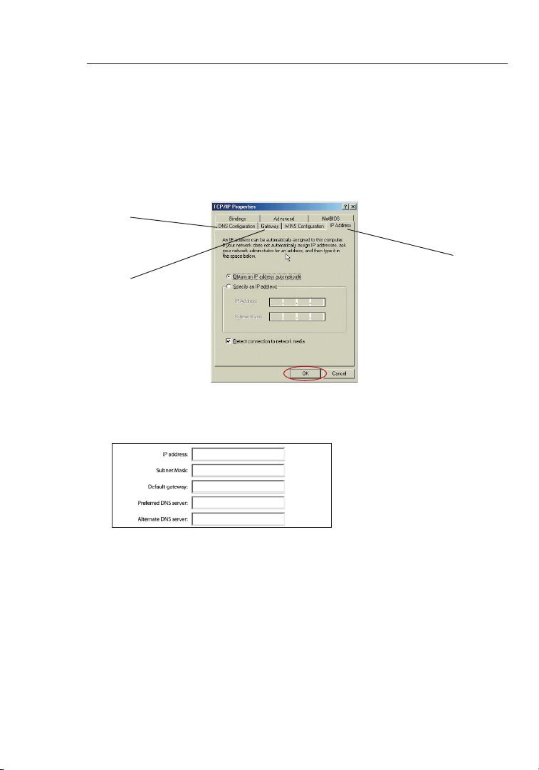
2. Select “TCP/IP -> settings” for your installed network adapter. You will see
the following window.
(1)
(3)
(2)
3. If “Specify an IP address” is selected, your Router will need to be set up
for a static IP connection type. Write the address information in the table
below. You will need to enter this information into the Router.
4. Write the IP address and subnet mask from the “IP Address” tab (3).
5. Click the “Gateway” tab (2). Write the gateway address down in the chart.
6. Click the “DNS Configuration” tab (1). Write the DNS address(es) in the
chart.
7. If not already selected, select “Obtain an IP address automatically” on the
IP address tab. Click “OK”.
8. You will also need to delete the Gateway address from the Gateway tab
and DNS Configuration entries in order to properly be configured for
connection to the Belkin router.
Restart the computer. When the computer restarts, your network
adapter(s) are now configured for use with the Router.
Page 15
13
Setting Up your Computers
Set up the computer that is connected to the cable or DSL modem
by FIRST using these steps. You can also use these steps to add
computers to your Router after the Router has been set up to connect
to the Internet.
Manually Configuring Network Adapters in Mac OS
up to 9.x
In order for your computer to properly communicate with your Router,
you will need to change your Mac computer’s TCP/IP settings to
DHCP.
1. Pull down the Apple menu. Select “Control Panels” and
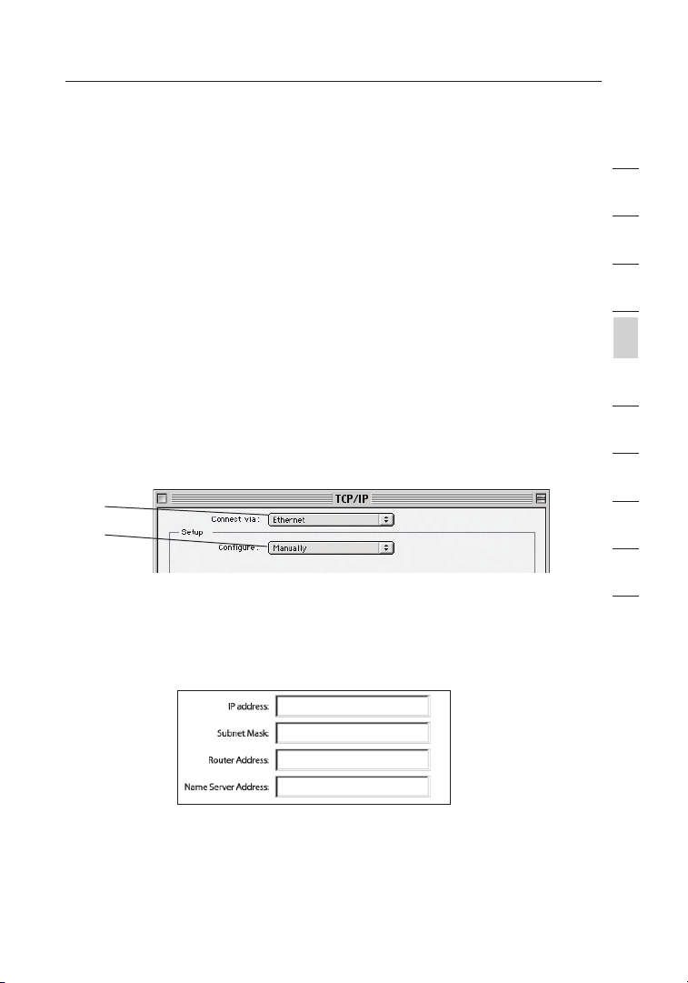
select “TCP/IP”.
2. You will see the TCP/IP control panel. Select “Ethernet Built-In”
or “Ethernet” in the “Connect via:” drop-down menu (1).
(1)
(2)
3. Next to “Configure” (2), if “Manually” is selected, your Router
will need to be set up for a static IP connection type. Write the
address information in the table below. You will need to enter
this information into the Router.
1
2
3
4
section
5
6
7
8
9
10
12
13
Page 16
Setting Up your Computers
1514
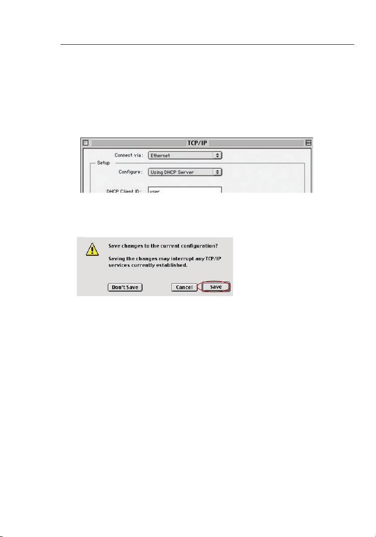
4. If not already set, at “Configure:”, choose “Using DHCP Server”.
This will tell the computer to obtain an IP address from the
Router.
5. Close the window. If you made any changes, the following
window will appear. Click “Save”.
Restart the computer. When the computer restarts, your network
settings are now configured for use with the Router.
Page 17
15
Setting Up your Computers
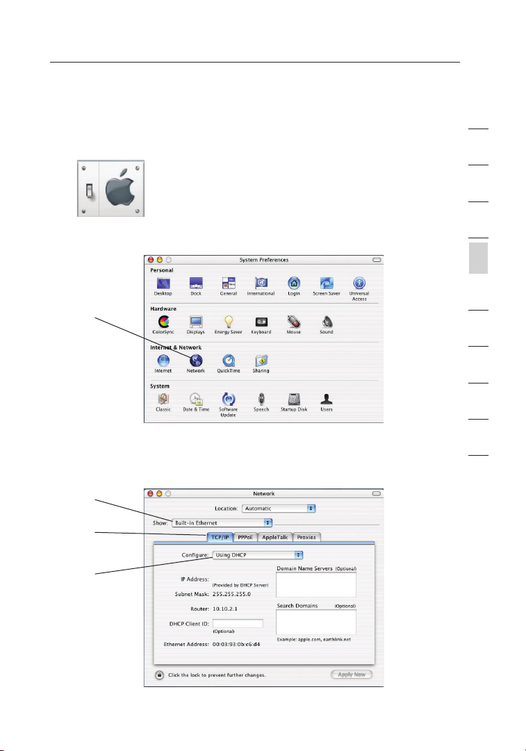
Manually Configuring Network Adapters in Mac OS X
1.
Click on the “System Preferences” icon.
2. Select “Network” (1) from the “System Preferences” menu.
(1)
3. Select “Built-in Ethernet” (2) next to “Show” in the Network menu.
(2)
(3)
1
2
3
4
section
5
6
7
8
9
10
12
(4)
15
Page 18
Setting Up your Computers
1716
4. Select the “TCP/IP” tab (3). Next to “Configure” (4), you should
see “Manually” or “Using DHCP”. If you do not, check the
PPPoE tab (5) to make sure that “Connect using PPPoE” is NOT
selected. If it is, you will need to configure your Router for a
PPPoE connection type using your user name and password.
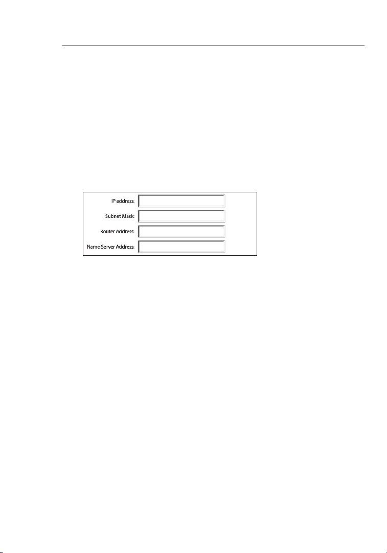
5. If “Manually” is selected, your Router will need to be set up for
a static IP connection type. Write the address information in
the table below. You will need to enter this information into the
Router.
6. If not already selected, select “Using DHCP” next to “Configure”
(4), then click “Apply Now”.
Your network adapter(s) are now configured for use with the Router.
Page 19
17
Setting Up your Computers
Recommended Web Browser Settings
In most cases, you will not need to make any changes to your web
browser’s settings. If you are having trouble accessing the Internet or
the advanced web-based user interface, then change your browser’s
settings to the recommended settings in this section.
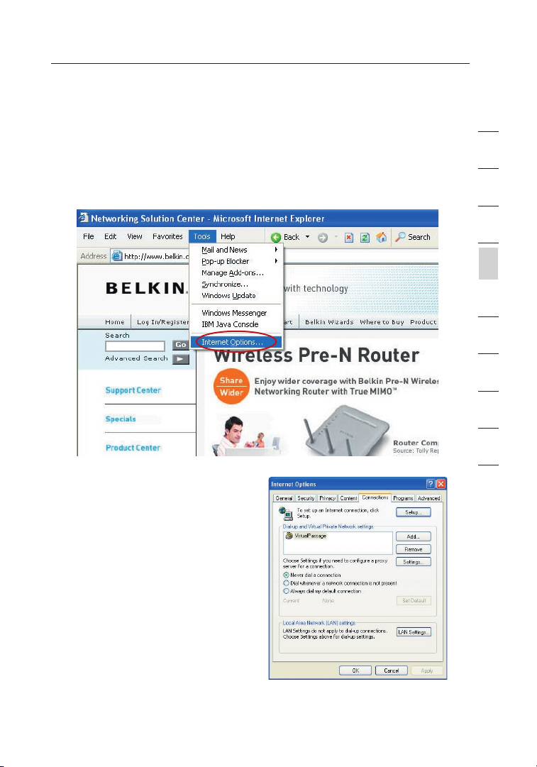
Internet Explorer 4.0 or Higher
1.
Start your web browser. Select
“Tools” then “Internet Options”.
2. In the “Internet Options” screen,
there are three selections:
“Never dial a connection”, “Dial
whenever a network connection
is not present”, and “Always dial
my default connection”. If you
can make a selection, select
“Never dial a connection”. If you
cannot make a selection, go to
the next step.
3. Under the “Internet Options”
screen, click on “Connections” and select “LAN Settings…”.
1
2
3
4
section
5
6
7
8
9
10
12
17
Page 20
1918
Setting Up your Computers
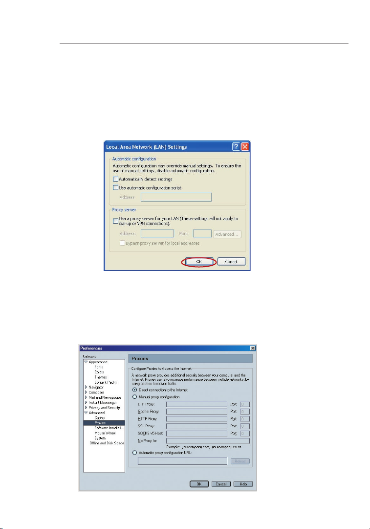
4. Make sure there are no check marks next to any of the displayed
options: “Automatically detect settings”, “Use automatic
configuration script”, and “Use a proxy server”. Click “OK”. Then
click “OK” again in the “Internet Options” page.
Netscape Navigator 4.0 or Higher
1.
Start Netscape. Click on “Edit” then “Preferences”.
2. In the “Preferences” window, click on “Advanced” then select
“Proxies”. In the “Proxies” window, select “Direct connection to
the Internet”.
Page 21
19
Configuring your Router with the Setup Wizard
Running the Setup Wizard
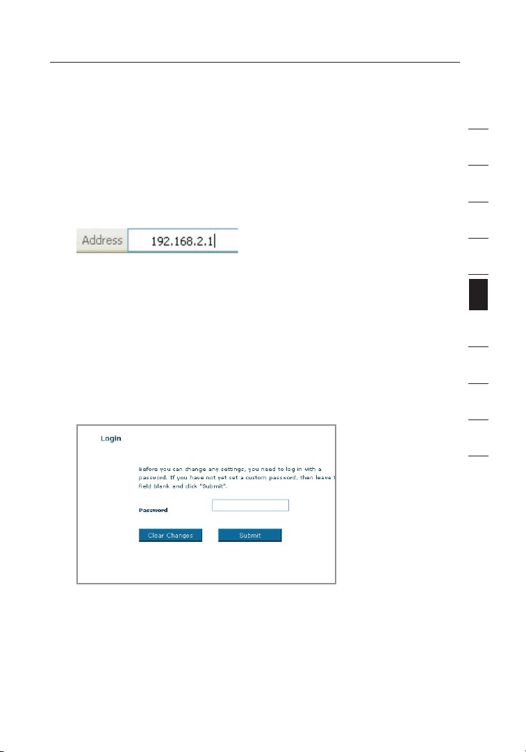
1. You can access the web-based management user interface of the
Router using the Internet browser on a computer connected to
the Router. Type “192.168.2.1” (do not type in anything else such
as “http://” or “www”) in your browser’s address bar. Then press
the “Enter” key.
Note: It is strongly recommended that you use a computer
physically connected to the Router with an RJ45 cable for initial
setup. Using a wirelessly connected computer for initial setup is
not recommended.
2. The following screen will appear in your browser to prompt you
to login. The Router ships with no password entered. In the login
screen, leave the password blank and click the “Submit” button
to log in.
1
2
3
4
5
section
6
7
8
9
10
12
Note: It is strongly recommended that you change the password
to your own for increased security. Please read the following
section, entitled “Manually Configuring your Router”, for details
on how to change your password and to reference other
security features.
19
Page 22
Configuring your Router with the Setup Wizard
2120
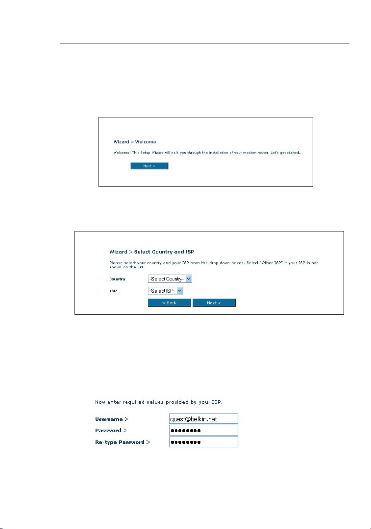
3. The Setup Wizard will start automatically for express
configuration (recommended) Click “Next” to continue.
4. The first step is to select your country and ISP,
and click “Next”. If your country and/or ISP is not
listed, select “Other Country” or “Other ISP.”
5. Now fill in the username and password you were supplied
by your Internet Service Provider (ISP) in to the blank fields.
It is important that the correct user name and password
are entered otherwise the connection will fail. Your ISP
will be able to confirm your user name and password.
Note: For more detailed instruction on other connection types, please refer
to the “Manually Configuring your Router” section of this User Manual.
Page 23
21
Configuring your Router with the Setup Wizard
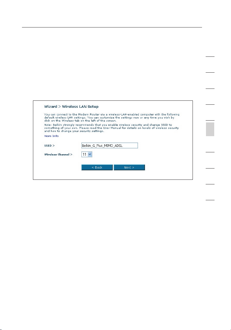
6. Now the Wireless LAN Setup screen will show. You can connect
to the Router via a wireless-LAN-enabled computer with the
following default wireless LAN settings:
SSID = Belkin G+ MIMO ADSL
Wireless Channel = Auto
Security = off
Note: Belkin strongly recommends that you enable wireless security
to WEP or WPA and change SSID to something of your own. Please
read the User Manual for details on levels of wireless security and how
to change your security settings
1
2
3
4
5
section
6
7
8
9
10
12
21
Page 24
2322
Configuring Your Router with the Setup Wizard
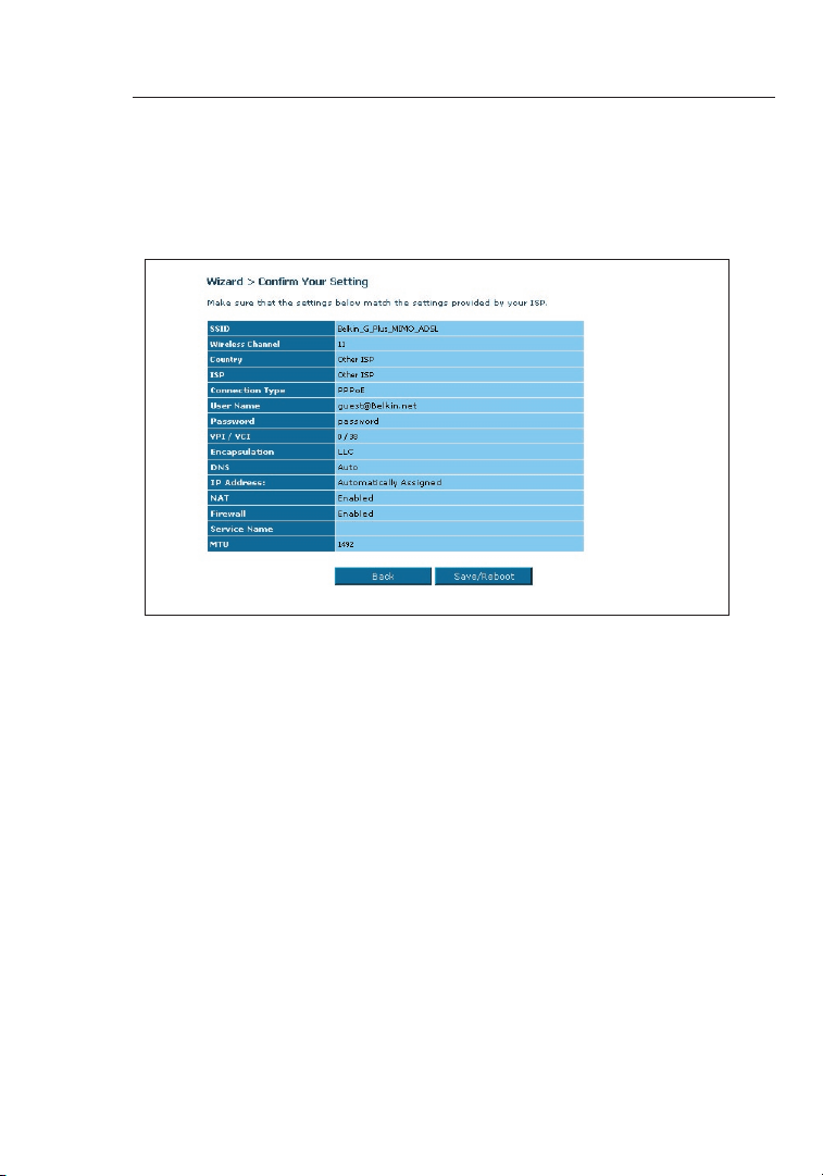
7. Double-check the settings shown on the following screen.
You can click “Back” to change the settings or click “Next” to
confirm
Note: You can always restart the Setup Wizard or use the Navigation
Menu on the left to change your setting.
Page 25
23
Manually Configuring your Router
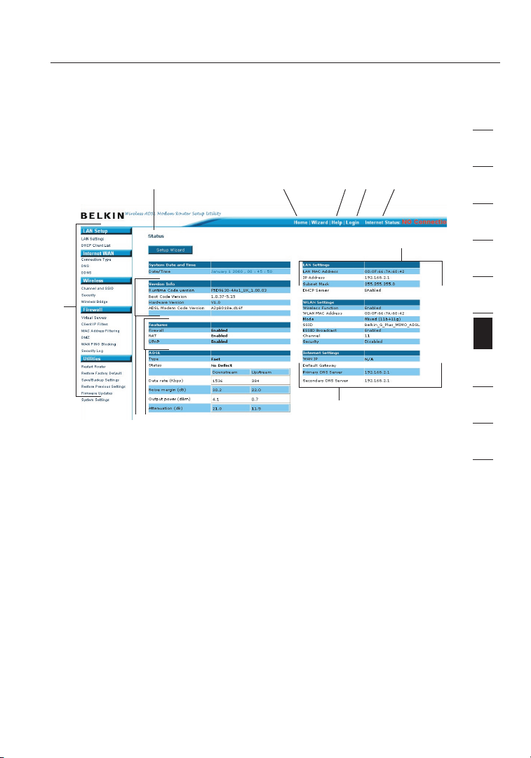
Understanding the Web-Based User Interface
The home page shows you a quick view of the Router’s status and
settings. All advanced setup pages can be reached from this page.
(10)
(1)
(9)
(7)
1. Quick-Navigation Links
You can go directly to any of the Router’s UI pages by clicking
directly on these links. The links are divided into logical
categories and grouped by tabs to make finding a particular
setting easier to find. Clicking on the header of each tab will
show you a short description of the tab’s function.
2. Home Button
The “Home” button is available in every page of the UI. Pressing
this button will take you back to the home page.
3. Help Button
The “Help” button gives you access to the Router’s help pages.
Help is also available on many pages by clicking “more info” next
to certain sections of each page.
4. Login/Logout Button
This button enables you to log in and out of the Router with the
press of one button. When you are logged into the Router, this
button will change to read “Logout”. Logging into the Router will
(2) (5)(4)(3)
23
(6)
(8)
1
2
3
4
5
6
section
7
8
9
10
12
Page 26

Manually Configuring your Router
2524
take you to a separate login page where you will need to enter a
password. When you are logged into the Router, you can make
changes to the settings. When you are finished making changes,
you can log out of the Router by clicking the “Logout” button.
For more information about logging into the Router, see the
section called “Logging into the Router”.
5. Internet Status Indicator
This indicator is visible in all pages of the Router, showing
the connection status of the Router. When the indicator says
“connection OK” in GREEN, the Router is connected to the
Internet. When the Router is not connected to the Internet, the
indicator will read “no connection” in RED. The indicator is
automatically updated when you make changes to the settings of
the Router.
6. LAN Settings
Shows you the settings of the Local Area Network (LAN) side of
the Router. Changes can be made to the settings by clicking the
“LAN” “Quick Navigation” link on the left side of the screen.
7. Features
Shows the status of the Router’s UPnP, NAT, and firewall
features. Changes can be made to the settings by clicking on any
one of the links or by clicking the “Quick Navigation” links on the
left side of the screen.
8. Internet Settings
Shows the settings of the Internet/WAN side of the Router that
connects to the Internet. Changes to any of these settings can be
made by clicking on the “Internet/WAN” “Quick Navigation” link
on the left side of the screen.
9. Version Info
Shows the firmware version, boot-code version, hardware
version, and serial number of the Router.
10. Page Name
The page you are on can be identified by this name. This manual
will sometimes refer to pages by name. For instance, “LAN > LAN
Settings” refers to the “LAN Settings” page.
Page 27
25
Manually Configuring your Router
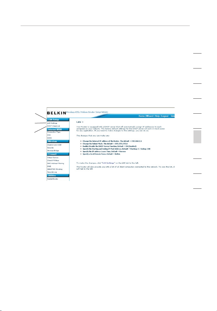
Changing LAN Settings
All settings for the internal LAN setup of the Router can be viewed
and changed here.
Clicking on the header of the LAN tab (1) will take you to the LAN
tab’s header page. A quick description of the functions can be
found here. To view the settings or make changes to any of the LAN
settings, click on “LAN Settings” (2) or to view the list of connected
computers, click on “DHCP Client List” (3).
(1)
(2)
(3)
1
2
3
4
5
6
section
7
8
9
10
12
25
Page 28
Manually Configuring your Router
2726
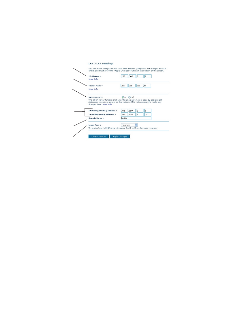
LAN Settings
(1)
(2)
(3)
(4)
(6)
(5)
1. IP Address
The “IP address” is the internal IP address of the Router.
The default IP address is “192.168.2.1”. To access the setup
interface, type this IP address into the address bar of your
browser. This address can be changed if needed. To change
the IP address, type in the new IP address and click “Apply
Changes”. The IP address you choose should be a non-routable
IP. Examples of a non-routable IP are:
192.168.x.x (where x is anything between 0 and 255)
10.x.x.x (where x is anything between 0 and 255)
2. Subnet Mask
There is no need to change the subnet mask as the router will
automatically adjust the length based on the IP address type.
3. DHCP Server
The DHCP server function makes setting up a network very easy
by assigning IP addresses to each computer on the network
automatically. The default setting is “On”. The DHCP server can
be turned OFF if necessary, however, in order to do so you must
manually set a static IP address for each computer on your network.
To turn off the DHCP server, select “Off” and click “Apply Changes”.
4. IP Pool
The IP Pool is the range of IP addresses set aside for dynamic
assignment to the computers on your network. The default is
Page 29

27
Manually Configuring your Router
2–100 (99 computers). If you want to change this number, you
can do so by entering a new starting and ending IP address and
clicking on “Apply Changes”. The DHCP server can assign 100 IP
addresses automatically. This means that you cannot specify an
IP address pool larger than 100 computers. For example, starting
at 50 means you have to end at 150 or lower so as not to exceed
the 100-client limit. The starting IP address must be lower in
number than the ending IP address.
5. Lease Time
Lease time is the length of time the DHCP server will reserve
the IP address for each computer. We recommend that you
leave the lease time set to “Forever”. The default setting is
“Forever”, meaning that any time a computer is assigned an IP
address by the DHCP server, the IP address will not change
for that particular computer. Setting lease times for shorter
intervals, such as one day or one hour, frees IP addresses after
the specified period of time. This also means that a particular
computer’s IP address may change over time. If you have set any
of the other advanced features of the Router, such as DMZ or
client IP filters, these are dependent on the IP address. For this
reason, you will not want the IP address to change.
6. Local Domain Name
The default setting is “Belkin”. You can set a local domain name
(network name) for your network. There is no need to change this
setting unless you have a specific advanced need to do so. You
can name the network anything you want such as “MY NETWORK”.
1
2
3
4
5
6
section
7
8
9
10
12
27
Page 30
Manually Configuring your Router
2928
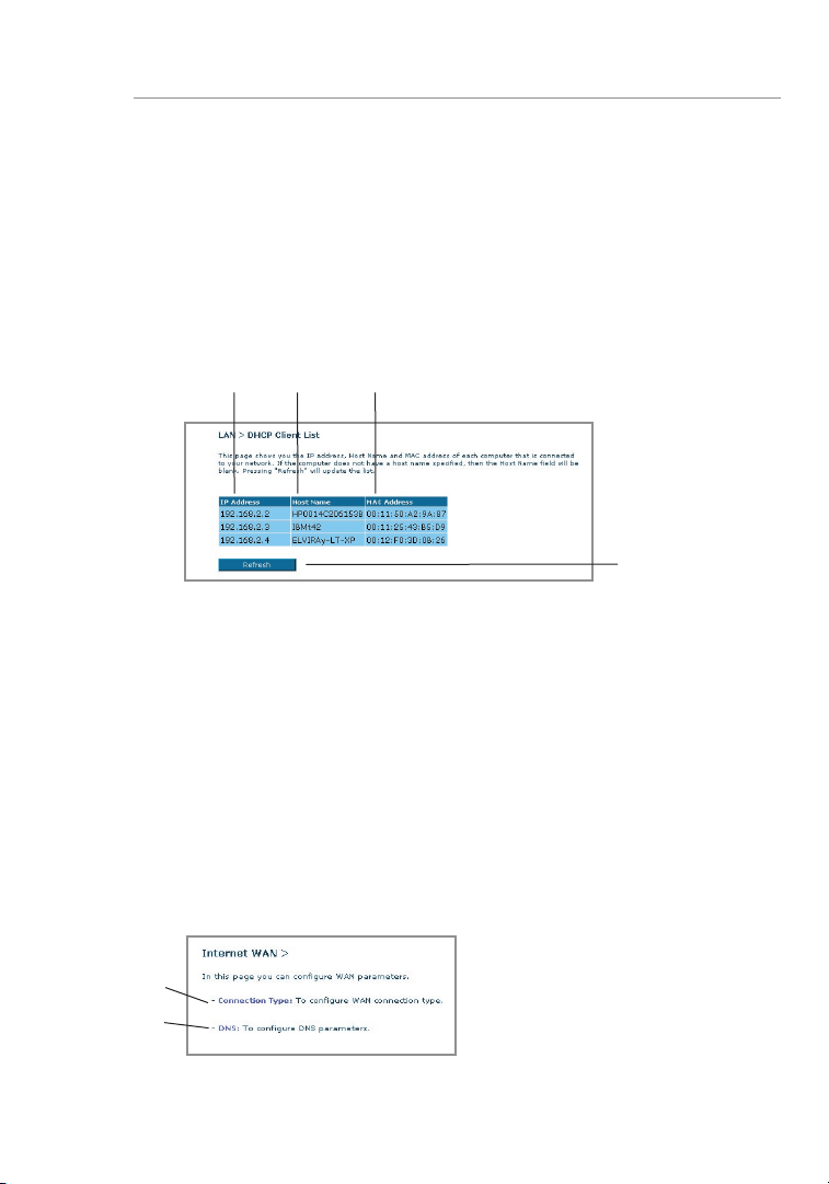
DHCP Client List
You can view a list of the computers (known as clients), which are
connected to your network. You are able to view the IP address (1) of
the computer, the host name (2) (if the computer has been assigned
one), and the MAC address (3) of the computer’s Network Interface
Card (NIC). Pressing the “Refresh” (4) button will update the list. If
there have been any changes, the list will be updated.
(1) (2) (3)
(4)
Internet WAN
The “Internet WAN” tab is where you will set up your Router to connect
to your Internet Service Provider. The Router is capable of connecting
to virtually any ADSL Service Provider’s system provided you have
correctly configured the Router’s settings for your ISP’s connection
type. Your connection settings are provided to you by your ISP. To
configure the Router with the settings that your ISP gave you, click
“Connection Type” (1) on the left side of the screen. Select the
connection type you use. If your ISP gave you DNS settings, clicking
“DNS” (2) allows you to enter DNS address entries for ISPs that require
specific settings.
When you have finished making settings, the “Internet Status” indicator
will read “Connection OK” if your Router is set up properly.
(1)
(2)
Page 31

29
Manually Configuring your Router
1
Connection Type
From the “Connection Type” page, you can select one of these five
connection types based on the instruction provided by your ISP:
• PPPoE
• PPPoA
• Dynamic IP (1483 Bridged
• Static IP (IPOA)
• Modem Only (Disable Internet Sharing)
Note: See Appendix C in this User Manual for some common DSL
Internet setting parameters. If you are not sure, please contact your ISP.
Select the type of connection you use by clicking the radio button
next to your connection type and then clicking “Next” (2).
(1)
)
(1)
2
3
4
5
6
section
7
8
9
10
12
(2)
29
Page 32

Manually Configuring your Router
3130
Setting your ISP Connection Type to PPPoE or PPPoA
PPPoE (Point-to-Point Protocol over Ethernet) is the standard
method of connecting networked devices. It requires a user name and
password to access the network of your ISP for connecting to the
Internet. PPPoA (PPP over ATM) is similar to PPPoE, but is mostly
implemented in the UK. Select PPPoE or PPPoA and click “Next”.
Then enter the information provided by your ISP, and click “Apply
Changes” to activate your settings.
(1)
(2)
(3)
(4)
(5)
(6)
(7)
1. User Name - Enter the user name. (Assigned by your ISP).
2. Password - Enter your password. (Assigned by your ISP).
3. Retype Password - Confirm the password. (Assigned by your ISP).
4. VPI/VCI - Enter your Virtual Path Identifier (VPI) and Virtual Circuit
Identifier (VCI) parameter here. (Assigned by your ISP).
5. Encapsulation - Select your encapsulation type (supplied by your ISP)
to specify how to handle multiple protocols at the ATM transport layer.
VC-MUX: PPPoA Virtual Circuit Multiplexer (null encapsulation) allows
only one protocol running per virtual circuit with fewer overheads.
LLC: PPPoA Logical Link Control allows multiple protocols running over
one virtual circuit (more overhead).
6. Dial on Demand - By selecting “Dial on Demand” your Router will
automatically connect to the Internet when a user opens up a web browser.
7. Idle Time (Minutes) - Enter the maximum idle time for the Internet
connection. After this time has been exceeded, the connection will
be terminated.
Page 33

31
Manually Configuring your Router
Setting your Connection Type to Dynamic IP (1483 Bridged)
This connection method bridges your network and ISP’s network
together. The Router will obtain an IP address automatically from your
ISP’s DHCP server.
(1)
(2)
1. VPI/VCI - Enter your Virtual Path Identifier (VPI) and Virtual Circuit
Identifier (VCI) parameter here. These identifiers are assigned by your ISP.
2. Encapsulation - Select LLC or VC MUX your ISP uses.
1
2
3
4
5
6
section
7
8
9
10
12
31
Page 34

Manually Configuring your Router
3332
Setting your ISP Connection to Static IP (IPoA)
This connection type is also called “Classical IP over ATM” or “CLIP”,
which your ISP provides a fixed IP for your Router to connect to the
Internet.
(1)
(2)
(3)
(4)
(5)
1. WAN IP Address – Enter an IP address assigned by your ISP for
the Router WAN interface.
2. WAN Subnet Mask - Enter a subnet mask assigned by your ISP.
3. Default Route - Enter a default gateway IP address. If the Router
cannot find the destination address within its local network, it will
forward the packets to the default gateway assigned by your ISP.
4. VPI/VCI - Enter your Virtual Path Identifier (VPI) and Virtual Circuit
Identifier (VCI) parameter here. These identifiers are assigned by
your ISP.
5. Encapsulation - Select LLC or VC MUX your ISP uses.
Page 35

33
Manually Configuring your Router
Setting your Connection Type to Modem Only (Disable
Internet Sharing)
In this mode, the Router simply acts as a bridge passing packets
across the DSL port. It requires additional software to be installed on
your computers in order to access the Internet.
(1)
1. VPI/VCI - Enter your Virtual Path Identifier (VPI) and Virtual Circuit
Identifier (VCI) parameter here. (Assigned by your ISP).
DNS (Domain Name Server) Settings
A “Domain Name Server” is a server located on the Internet that
translates Universal Resource Links (URLs) like “www.belkin.com” to
IP addresses. Many ISPs do not require you to enter this information
into the Router. The “Automatic from ISP” box (1) should be checked
if your ISP did not give you a specific DNS address. If you are using a
static IP connection type, then you may need to enter a specific DNS
address and secondary DNS address for your connection to work
properly. If your connection type is dynamic or PPPoE, it is likely that
you do not have to enter a DNS address. Leave the “Automatic from
ISP” box checked. To enter the DNS address settings, uncheck the
“Automatic from ISP” box and enter your DNS entries in the spaces
provided. Click “Apply Changes” (2) to save the settings.
1
2
3
4
5
6
section
7
8
9
10
12
(1)
33
(2)
Page 36

Manually Configuring your Router
3534
Using Dynamic DNS
The Dynamic DNS service allows you to alias a dynamic IP address
to a static host name in any of the many domains DynDNS.org offers,
allowing your network computers to be more easily accessed from
various locations on the Internet. DynDNS.org provides this service,
for up to five host names, free to the Internet community.
The Dynamic DNSSM service is ideal for a home website, file
server, or to make it easy to access your home PC and stored files
while you’re at work. Using the service can ensure that your host
name always points to your IP address, no matter how often your
ISP changes it. When your IP address changes, your friends and
associates can always locate you by visiting yourname.dyndns.org
instead!
To register free for your Dynamic DNS host name, please visit
http://www.dyndns.org.
Setting up the Router’s Dynamic DNS Update Client
You must register with DynDNS.org’s free update service before using
this feature. Once you have your registration, follow the directions
below.
1. Select “DynDNS.org” from the dropdown box. Click “Apply
Changes”
2. Enter your DynDNS.org user name in the “User Name” field (1).
3. Enter your DynDNS.org password in the “Password” field (2).
4. Enter the DynDNS.org domain name you set up with DynDNS.org
in the “Domain Name” field (3).
5. Click “Apply Changes” to update your IP address.
Whenever your IP address assigned by your ISP changes, the Router
will automatically update DynDNS.org’s servers with your new
IP address. You can also do this manually by clicking the “Apply
Changes” button (4)
.
Page 37

35
Manually Configuring your Router
Wireless
The “Wireless” tab lets you make changes to the wireless network settings. From
this tab, you can make changes to the wireless network name (SSID), operating
channel, and encryption security settings.
Channel and SSID
(1)
(2)
1. Changing the Wireless Channel
There are a number of operating channels you can choose from. In the United
States, there are 11 channels. In the United Kingdom and most of Europe, there
are 13 channels. In a small number of other countries, there are other channel
requirements. Your Router is configured to operate on the proper channels for
the country you reside in. The default channel is 11 (unless you are in a country
that does not allow channel 11). The channel can be changed if needed. If there
are other wireless networks operating in your area, your network should be set to
operate on a channel that is different than the other wireless networks. For best
performance, use a channel that is at least five channels away from the other
wireless networks. For instance, if another network is operating on channel 11, then
set your network to channel 6 or below. To change the channel, select the channel
from the drop-down list. Click “Apply Changes”. The change is immediate.
1
2
3
4
5
6
section
7
8
9
10
12
2. Changing the Wireless Network Name (SSID)
To identify your wireless network, a name called the SSID (Service Set Identifier)
is used. The default SSID of the Router is “belkin54g”. You can change this to
anything you want to or you can leave it unchanged. If there are other wireless
networks operating in your area, you will want to make sure that your SSID is
unique (does not match that of another wireless network in the area). To change
the SSID, type in the SSID that you want to use in the SSID field
“Apply Changes”
SSID, your wireless-equipped computers may also need to be reconfigured to
connect to your new network name. Refer to the documentation of your wireless
network adapter for information on making this change.
(2)
. The change is immediate. If you make a change to the
35
(1)
and click
Page 38

Manually Configuring your Router
3736
3. Using the ESSID Broadcast Feature
For security purposes, you can choose not to broadcast your network’s SSID.
Doing so will keep your network name hidden from computers that are scanning
for the presence of wireless networks. To turn off the broadcast of the SSID,
remove the tick from the tick box next to the option, Broadcast SSID. The change
is immediate. Each computer now needs to be set to connect to your specific
SSID; an SSID of “ANY” will no longer be accepted. Refer to the documentation
of your wireless network adapter for information on making this change.
Note: This advanced feature should be employed by advanced users only.
4. Using the Wireless Mode Switch
Your router can operate in either two different wireless modes:
• 802.11b &
of both 802.11b and 802.11g connect to your network.
• 802.11g -
This option gives the best performance but will not allow 802.11b clients to
connect.
5. Protected Mode Switch
As part of the 802.11g specification, Protected mode ensures proper
operation of 802.11g clients and access points when there is heavy
802.11b traffic in the operating environment. When Protected mode
is ON, 802.11g scans for other wireless network traffic before it
transmits data. Therefore, using this mode in environments with
HEAVY 802.11b traffic or interference achieves best performance
results. If you are in an environment with very little—or no—wireless
network traffic, your best performance will be achieved with Protected
mode OFF.
802.11g- Choose this option if you plan to have wireless clients
Use this mode if there are no 802.11b clients in the network.
Page 39

37
Manually Configuring your Router
Encryption/Security
Securing your Wi-Fi Network
Here are a few different ways you can maximize the security of your
wireless network and protect your data from prying eyes and ears.
This section is intended for the home, home office, and small office
user. At the time of this User Manual’s publication, there are four
encryption methods available.
Name
Acron ym 64-bit WEP 128-b it WEP WPA-T KIP/AES
Secur ity Good Better Best Best
Featu res Static keys Static keys Dynam ic key
64-Bit Wired
Equivalent
Privacy
Encry ption
keys based
on RC4
algor ithm
(typi cally 40bit keys)
128-Bit Wired
Equivalent
Privacy
More secure
than 64-bit
WEP using a
key length of
104 bits plus
24 additional
bits of systemgener ated data
Wi-Fi Protected
Access-TKIP
(or just WPA)
encry ption
and mutual
authe ntication
TKIP (Temporal
Key Integrity
Proto col)
added so
that keys are
rotat ed and
encry ption is
stren gthened
WEP (Wired Equivalent Privacy)
WEP is a common protocol that adds security to all Wi-Fi-compliant
wireless products. WEP was designed to give wireless networks the
equivalent level of privacy protection as a comparable wired network.
Wi-Fi Protected
Access 2
WPA2- AES (or
just WPA2)
Dynam ic key
encry ption
and mutual
authe ntication
AES (Advanced
Encry ption
Stand ard) does
not cause any
throu ghput
loss
1
2
3
4
5
6
section
7
8
9
10
12
64-Bit WEP
64-bit WEP was first introduced with 64-bit encryption, which
includes a key length of 40 bits plus 24 additional bits of systemgenerated data (64 bits total). Some hardware manufacturers refer
to 64-bit as 40-bit encryption. Shortly after the technology was
introduced, researchers found that 64-bit encryption was too easy to
decode.
37
Page 40

Manually Configuring your Router
3938
128-Bit WEP
As a result of 64-bit WEP’s potential security weaknesses, 128Bit
WEP was developed as a more secure method of encryption. 128-bit
encryption includes a key length of 104 bits plus 24 additional bits of
system-generated data (128 bits total). Some hardware manufacturers
refer to 128-bit as 104-bit encryption.
Most of the new wireless equipment in the market today supports
both 64-bit and 128-bit WEP encryption, but you might have older
equipment that only supports 64-bit WEP. All Belkin wireless products
will support both 64-bit and 128-bit WEP.
Encryption Keys
After selecting either the “64-bit” or “128-bit WEP” encryption mode,
it is critical that you generate an encryption key. If the encryption key
is not consistent throughout the entire wireless network, your wireless
networking devices will be unable to communicate with one another
on your network and you will not be able to successfully communicate
within your network.
You can enter your key by typing in the hex key manually, or you can
type in a passphrase in the “Passphrase” field and click “Generate”
to create a key. A hex (hexadecimal) key is a mixture of numbers and
letters from A–F and 0–9. For 64-bit WEP, you need to enter 10 hex
characters. For 128-bit WEP, you need to enter 26 hex characters.
The WEP passphrase is NOT the same as a WEP key. Your wireless
card uses this passphrase to generate your WEP keys, but different
hardware manufacturers might have different methods for generating
the keys. If you have equipment from multiple vendors in your
network, you can use the hex WEP key from your Router or access
point and enter it manually into the hex WEP key table in your
wireless card’s configuration screen.
Using a Hexadecimal Key
A hexadecimal key is a mixture of numbers and letters from A–F and
0–9. 64-bit keys are five two-digit numbers. 128-bit keys are 13 twodigit Characters.
For instance:
AF 0F 4B C3 D4 = 64-bit key
C3 03 0F AF 0F 4B B2 C3 D4 4B C3 D4 E7 = 128-bit key
In the boxes below, make up your key by writing in two characters
Page 41

39
Manually Configuring your Router
between A–F and 0–9 in each box. You will use this key to program the
encryption settings on your Router and your wireless computers.
Note to Mac users: Original Apple AirPort® products support 64-bit
encryption only. Apple AirPort 2 products can support 64-bit or 128bit encryption. Please check your product to see which version you are
using. If you cannot configure your network with 128-bit encryption, try
64-bit encryption.
WPA (Wi-Fi Protected Access)
WPA (Wi-Fi Protected Access) is a new Wi-Fi standard that was designed
to improve upon the security features of WEP. To use WPA security,
the drivers and software of your wireless equipment must be upgraded
to support WPA. These updates will be found on the wireless vendors’
websites. There are two types of WPA security: WPA-Personal (PSK) and
WPA-Enterprise (RADIUS).
WPA-Personal (PSK)
This method uses what is known as a Pre-Shared key as the Network
key. A Network key is basically a password that is between eight and
63 characters long. It can be a combination of letters, numbers, or
characters. Each client uses the same Network key to access the network.
Typically, this is the mode that will be used in a home environment.
WPA-Enterprise (RADIUS)
With this system, a radius server distributes the Network key to the clients
automatically. This is typically found in a business environment. For a list
of Belkin wireless products that support WPA, please visit our website at
www.belkin.com/networking.
1
2
3
4
5
6
section
7
8
9
10
12
WPA2 (WiFi Protected Access)
WPA2 is the second generation of WPA based 802.11i standard. It
offers higher level of wireless security by combining advanced network
authentication and stronger AES encryption method. Like WPA security,
WPA2 is available in both WPA2-Personal (PSK) mode and WPA2Enterprise (RADIUS) mode. Typically, WPA2-Personal (PSK) is the mode
that will be used in a home environment, while WPA-Enterprise (RADIUS)
is implemented in a business environment where an external radius server
distributes the network key to the clients automatically.
39
Page 42

Manually Configuring your Router
4140
Wireless G Router
Wireless G Notebook
Network Car
d
Wireless G Desktop
Network Car
d
Wireless G Desktop
Network Car
d
Sharing the Same Network Keys
Most Wi-Fi products ship with security turned off. So once you have
your network working, you need to activate WEP or WPA or WPA2
and make sure your wireless networking devices are sharing the same
Network key.
The Wireless G+ MIMO Desktop Network Card cannot access the
network because it is using a different Network key than the Network
key that is configured on the Wireless G+ MIMO Router.
Network key=
MyPassword
Network key=
MyPassword
Network key=
MyPassword
Network key=
WRONG Password
Changing the Wireless Security Settings
Your Router is equipped with WPA/WPA2 (Wi-Fi Protected Access),
the latest wireless security standard. It also supports the legacy
security standard, WEP (Wired Equivalent Privacy). By default,
wireless security is disabled. To enable security, you must first
determine which standard you want to use. To access the security
settings, click “Security” on the Wireless tab.
Page 43

41
Manually Configuring your Router
1
WEP Setup
64-Bit WEP Encryption
1.
Select “64-bit WEP” from the drop-down menu.
2. After selecting your WEP encryption mode, you can enter your key
by typing in the hex key manually.
A hex (hexadecimal) key is a mixture of numbers and letters from A–F
and 0–9. For 64-bit WEP, you need to enter 10 hex characters.
For instance:
AF 0F 4B C3 D4 = 64-bit WEP key
3. Click “Apply Changes” to finish. Encryption in the Router is now
set. Each of your computers on your wireless network will now
need to be configured with the same security settings.
WARNING:
from a computer with a wireless client, you will lose your connection
until you enable security on your wireless client. Please be sure to
write down your key before applying changes
If you are configuring the Wireless Router or access point
2
3
4
5
6
section
7
8
9
10
12
41
Page 44

Manually Configuring your Router
4342
128-Bit WEP Encryption
1.
Select “128-bit WEP” from the drop-down menu.
2. After selecting your WEP encryption mode, you can enter your
key by typing in the hex key manually.
A hex (hexadecimal) key is a mixture of numbers and letters
from A–F and 0–9. For 128-bit WEP, you need to enter 26 hex
characters.
For instance:
C3 03 0F AF 0F 4B B2 C3 D4 4B C3 D4 E7 = 128-bit WEP key
3. Click “Apply Changes” to finish. Encryption in the Router is now
set. Each of your computers on your wireless network will now
need to be configured with the same security settings.
WARNING: If you are configuring the Wireless Router or access point
from a computer with a wireless client, you will lose your connection
until you enable security on your wireless client. Please be sure to
write down your key before applying changes.
WPA Setup
Note: To use WPA security, all your clients must be upgraded to drivers
and software that support it. At the time of this User Manual’s publication,
a security patch download is available free from Microsoft. This patch
works only with the Windows XP operating system. You also need to
download the latest driver for your Belkin Wireless G Desktop or Notebook
Network Card from the Belkin support site. Other operating systems are
not supported at this time. Microsoft’s patch only supports devices with
WPA-enabled drivers such as Belkin 802.11g products.
Page 45

43
Manually Configuring your Router
There are two types of WPA security: WPA-Personal (PSK) and WPAEnterprise (RADIUS). WPA-Personal (PSK) uses a so-called Pre-Shared key
as the security key. A Pre-Shared key is a password that is between eight
and 63 characters long. It can be a combination of letters, numbers, and
other characters. Each client uses the same key to access the network.
Typically, this mode will be used in a home environment.
WPA-Enterprise (RADIUS) is a configuration wherein a radius server
distributes the keys to the clients automatically. This is typically used
in a business environment.
Setting WPA-Personal (PSK)
1.
From the “Security Mode” drop-down menu, select “WPA/WPA2-PSK.
2. Select “WPA-PSK” for Authentication.
3. For Encryption Technique, select “TKIP”. This setting will have to be
identical on the clients that you set up.
4. Enter your Pre-Shared key. This can be from eight to 63 characters
and can be letters, numbers, or symbols. This same key must be used
on all of the clients that you set up. For example, your PSK might be
something like: “Smith family network key”.
1
2
3
4
5
6
section
7
8
9
10
12
5. Click “Apply Changes” to finish. You must now set all clients to
match these settings.
Setting WPA-Enterprise (RADIUS) Settings
If your network uses a radius server to distribute keys to the clients,
use this setting.
1. From the “Security Mode” drop-down menu, select “WPA/
WPA2—Enterprise (RADIUS)
43
Page 46

Manually Configuring your Router
4544
2. Select “WPA-RADIUS” for Authentication
3. For Encryption Technique, select “TKIP”. This setting will have to
be identical on the clients that you set up
4. Enter the IP address of the radius server into the “Radius
Server” fields.
5. Enter the radius key into the “Radius Key” field.
6. Enter the key interval. Key interval is how often the keys are
distributed (in packets).
7. Click “Apply Changes” to finish. You must now set all clients to
match these settings.
WPA2 Requirements
IMPORTANT: In order to use WPA2 security, all your computers and
wireless client adapters must be upgraded with patches, driver, and
client utility software that supported WPA2. At the time of this User
Manual’s publication, a couple security patches are available, for free
download, from Microsoft. These patches work only with the Windows
XP operating system. Other operating systems are not supported at
this time.
For Windows XP computer that does not have Service Pack 2 (SP2),
a file from Microsoft called “Windows XP Support Patch for Wireless
Protected Access (KB 826942)” is available for free download at http://
support.microsoft.com/?kbid=826942
For Windows XP with Service Pack 2, Microsoft has released a free
download to update the wireless client components to support WPA2
(KB893357). The update can be download from: http://support.microsoft.
com/default.aspx?scid=kb;en-us;893357
Page 47

45
Manually Configuring your Router
IMPORTANT: You also need to ensure that all your wireless client cards /
adapters support WPA2, and that you have downloaded and installed the
latest driver. Most of the Belkin Wireless cards have update driver available
for download from the Belkin support site: www.belkin.com/networking.
Setting WPA2-Personal (PSK)
1. From the “Security Mode” drop-down menu, select “WPA/WPA2-PSK
(PSK)”.
2. Select “WPA2-Personal (PSK)” for Authentication.
3. For Encryption Technique, select “AES” . This setting will have to be
identical on the clients that you set up.
4. Enter your Pre-Shared key. This can be from eight to 63 characters
and can be letters, numbers, or symbols. This same key must be used
on all of the clients that you set up. For example, your PSK might be
something like: “Smith family network key”.
5. Click “Apply Changes” to finish. You must now set all clients to
match these settings.
1
2
3
4
5
6
section
7
8
9
10
12
Setting WPA2-Enterprise (RADIUS) Settings
If your network uses a radius server to distribute keys to the clients,
use this setting.
1. From the “Security Mode” drop-down menu, select “WPA/WPA2—
Enterprise (RADIUS)”.
2. Select “WPA2-RADIUS” for Authentication
3. For Encryption Technique, select “AES”. This setting will have to be
identical on the clients that you set up
45
Page 48

Manually Configuring your Router
4746
4. Enter the IP address of the radius server into the “Radius Server” fields.
5. Enter the radius key into the “Radius Key” field.
6. Enter the key interval. Key interval is how often the keys are distributed
(in packets).
7. Click “Apply Changes” to finish. You must now set all clients to match
these settings.
IMPORTANT: Make sure your wireless computers are updated to work
with WPA2 and have the correct settings to get proper connection to the
Router.
Configuring your Computer’s Network Adapter to
Use Security
Note: This section provides information on how to configure network
adapter in your computers to use security. At this point, you
should already have your Wireless Router or access point set to
use WPA2 or WPA or WEP. In order for you to gain a wireless
connection, you will need to set your wireless notebook card
and wireless desktop card to use the same security settings.
Belkin G+ MIMO Network Cards feature easy-to-use Wireless
Networking Utility. Simply click on your wireless network name (SSID)
from the Available Networks list and enter your Pre-Share Key (PSK).
For more information please refer to Belkin Network Card’s user
manual.
Most computers can also setup to work with the Router from Wireless
Network Properties screen build-in your Microsoft Windows operating
system. The following are two of the examples:
Page 49

47
Manually Configuring your Router
Connecting your Computer to a Wireless Network that Requires a
64-Bit or 128-Bit WEP Key
1.
Double-click the “Signal Indicator” icon to bring up the “Wireless
Network” screen. The “Advanced” button will allow you to view
and configure more options of your wireless card.
2. Under the “Wireless Network Properties” tab, select a network
name from the “Available networks” list and click “Configure”.
3. Under “Data Encryption” select “WEP”.
4. Ensure the check box “Network key is provided for me
automatically” at the bottom is unchecked. If you are using this
computer to connect to a corporate network, please consult your
network administrator if this box needs to be checked.
5. Type your WEP key in the “Network key” box.
1
2
3
4
5
6
section
7
8
9
10
12
Important: A WEP key is a mixture of numbers and letters from A–F
and 0–9. For 128-bit WEP, you need to enter 26 characters. For 64bit WEP, you need to enter 10 characters. This Network key needs to
match the key you assign to your Wireless Router or access point.
6. Click “OK” to save the settings.
47
Page 50

Manually Configuring your Router
4948
Connecting your Computer to a Wireless Network that Requires
WPA-PSK (no server)
1.
Double-click the “Signal Indicator” icon to bring up the “Wireless
Network” screen. The “Advanced” button will allow you to view
and configure more options of your wireless card.
2. Under the “Wireless Networks” tab, select a network name from
the “Available networks” list and click “Configure”.
3. Under “Network Authentication” select “WPA-PSK (No Server)”.
4. Type your WPA key in the “Network key” box.
Important:
and 0–9. For WPA-PSK you can enter eight to 63 characters. This
Network key needs to match the key you assign to your Wireless
Router or access point.
WPA-PSK is a mixture of numbers and letters from A–Z
5. Click “OK” to save the settings.
Page 51

49
Manually Configuring your Router
Connecting your Computer to a Wireless Network that Requires
WPA (with radius server)
1.
Double-click the “Signal Indicator” icon to bring up the “Wireless
Network” screen. The “Advanced” button will allow you to view
and configure more options of your wireless card.
2. Under the “Wireless Networks” tab, select a network name from
the “Available networks” list and click “Configure”.
3. Under “Network Authentication” select WPA.
4. Under the “Authentication” tab, select the settings that are
indicated by your network administrator.
5. Click “OK” to save the settings.
1
2
3
4
5
6
section
7
8
9
10
12
Setting Up WPA/WPA2 for a Non-Belkin Wireless Desktop and
Wireless Notebook Cards
For non-Belkin WPA Wireless Desktop and Wireless Notebook Cards
that are not equipped with WPA/WPA2-enabled software, a file from
Microsoft called “Windows XP Support Patch for Wireless Protected
Access” is available as a free download.
Please Note: The file that Microsoft has made available works only
with Windows XP. Other operating systems are not supported at
this time.
49
Page 52

Manually Configuring your Router
5150
Important:
WPA/WPA2 and that you have downloaded and installed the latest driver from their
support site.
You also need to ensure that the wireless card manufacturer supports
Supported Operating Systems: • Windows XP Professional
• Windows XP Home Edition
Setting Up Windows XP Wireless Network Utility to Use WPA/WPA2-PSK
In order to use WPA-PSK, ensure you are using Windows Wireless Network Utility by
doing the following:
1.
Under Windows XP, click “Start >
Control Panel >
Network Connections”.
3.
Clicking on the “Wireless Networks”
tab will display the following
screen. Ensure the “Use Windows
to configure my wireless network
settings” check box is checked.
2.
Right-click on “Wireless Network
Connection”, and select
“Properties”.
5.
For a home or small business user,
select “WPA-PSK” or WPA2-PSK
under “Network Authentication”.
4.
Under the “Wireless Networks” tab,
click the “Configure” button, and you
will see the following screen.
Note: Select “WPA” if you are using this
computer to connect to a corporate network
that supports an authentication server such
as a radius server. Please consult your
network administrator for further information.
Page 53

51
Manually Configuring your Router
6.
Select “TKIP” or “AES” under “Data Encryption”. This setting will have to be
identical to the Router that you set up.
7.
Type in your encryption key in the
“Network Key” box.
8.
Click “OK” to apply settings.
Wireless Bridge
Wireless Bridging or Wireless Distribution System (WDS) is used to connect Wireless
Routers and Access points together to extend a network.
Click on the Drop down menu next to ‘Bridge Mode’ to select either:
Disabled:
To disable
Wireless
Bridging
(default)
Important: Enter your Pre-Shared key.
This can be from eight to 63 characters
and can be letters, numbers, or symbols.
This same key must be used on all of the
clients that you set up.
1
2
3
4
5
6
section
7
8
9
10
Manual:
To enter
the wireless
MAC
address(es)
of the
Access
Points to
bridge with,
manually.
12
51
Page 54

Manually Configuring your Router
5352
1 Wireless channels must match between Router and AP.
2 Security settings (WEP) must match between Router and AP.
3 If MAC filtering is enabled, user must be sure to add the WLAN MAC
address(es) of the Router/AP in order to allow communication with each
other.
4 If using a network protected by WPA, the SSID on both Access Points
must be the same.
Firewall
Your Router is equipped with a firewall that will protect your network
from a wide array of common hacker attacks including:
• IP Spoofing
• Land Attack
• Ping of Death (PoD)
• Denial of Service (DoS)
• IP with zero length
• Smurf Attack
• TCP Null Scan
• SYN flood
• UDP flooding
• Tear Drop Attack
• ICMP defect
• RIP defect
• Fragment flooding
The firewall also masks common ports that are frequently used to
attack networks. These ports appear to be “Stealth”, meaning that
essentially they do not exist to a would-be hacker. You can turn the
firewall function off if needed; however, it is recommended that you
leave the firewall enabled. Disabling the firewall protection will not
leave your network completely vulnerable to hacker attacks, but it is
recommended that you leave the firewall enabled.
Page 55

53
Manually Configuring your Router
Virtual Servers
Virtual servers allow you to route external (Internet) calls for services such
as a web server (port 80), FTP server (Port 21), or other applications,
through your Router to your internal network. Since your internal
computers are protected by a firewall, machines from the Internet cannot
get to them because they cannot be “seen”. If you need to configure the
virtual server function for a specific application, you will need to contact
the application vendor to find out which port settings you need. You can
manually input this port information into the Router.
Choosing an Application
A list of popular applications has been included to choose from. Click
on “Select a Service” then select your application from the drop-down
list. The settings will be transferred to the first row available. Click
“Add” to save the setting for that application.
1
2
3
4
5
6
section
7
8
9
10
12
Manually Entering Settings into the Virtual Server
To manually enter settings, click on “Custom Server” and enter
a name for the server. Enter the Server IP address in the space
provided for the internal machine and the port(s) required to pass.
Then select the protocol type (TCP or UDP), and then click “Add”.
Opening ports in your firewall can pose a security risk. You can
enable and disable settings very quickly. It is recommended that you
disable the settings when you are not using a specific application.
53
Page 56

Manually Configuring your Router
5554
Client IP Filters
The Router can be configured to restrict access to the Internet, email, or
other network services at specific days and times.
(1) (2) (3) (4)
To restrict Internet access to a single computer for example, enter
a name of the filter in “Filter Name” box
computer you wish to restrict access to in the IP field (2). Next, enter
“80:80” in the Port field (3). Select protocol from the “Protocol”
drop-down box (4). Click “Apply Changes”. The computer at the IP
address you specified will now be blocked from Internet access.
MAC Address Filtering
The MAC address filter is a powerful security feature that allows you
to specify which computers are allowed on the network. Any computer
attempting to access the network that is not specified in the filter list
will be denied access. When you enable this feature, you must enter a
name for the user and the MAC address of each client on your network
to allow network access. Next, click “Add” to save the settings.
(1) and IP address of the
Page 57

55
Manually Configuring your Router
DMZ (Demilitarized Zone)
If you have a client PC that cannot run an Internet application
properly from behind the firewall, you can open the client up to
unrestricted two-way Internet access. This may be necessary if the
NAT feature is causing problems with an application such as a game
or video conferencing application. Use this feature on a temporary
basis. The computer in the DMZ is not protected from
hacker attacks.
To put a computer in the DMZ, enter its LAN IP address in the “Private
IP” field and click “Apply Changes” for the change to take effect.
Blocking an ICMP Ping
Computer hackers use what is known as “pinging” to find potential
victims on the Internet. By pinging a specific IP address and
receiving a response from the IP address, a hacker can determine
that something of interest might be there. The Router can be set
up so it will not respond to an ICMP ping from the outside. This
heightens the level of security of your Router.
1
2
3
4
5
6
section
7
8
9
10
12
To turn off the ping response, select “Block ICMP Ping” (1) and click
“Apply Changes”. The Router will not respong to an ICMP Ping.
55
Page 58

Manually Configuring your Router
5756
Utilities
The “Utilities” screen lets you manage different parameters of the
Router and perform certain administrative functions.
Restart Router
Sometimes it may be necessary to restart or reboot the Router if it
begins working improperly. Restarting or rebooting the Router will
NOT delete any of your configuration settings.
Page 59

57
Manually Configuring your Router
Restarting the Router to Restore Normal Operation
1.
Click the “Restart Router” button.
2. The following message will appear. Click “OK” to restart your Router.
Restore Factory Defaults
Using this option will restore all of the settings in the Router to the
factory (default) settings. It is recommended that you back up your
settings before you restore all of the defaults.
1. Click the “Restore Defaults” button.
2. The following message will appear. Click “OK” to restore factory defaults.
1
2
3
4
5
6
section
7
8
9
10
12
57
Page 60

Manually Configuring your Router
5958
Saving/Backup Current Settings
You can save your current configuration by using this feature. Saving
your configuration will allow you to restore it later if your settings are
lost or changed. It is recommended that you back up your current
configuration before performing a firmware update.
1. Click “Save”. A window called “File Download” will open. Click “Save”.
2. A window will open that allows you to select the location in
which to save the configuration file. Select a location. There are
no restrictions on the file name, however, be sure to name the
file so you can locate it yourself later. When you have selected
the location and entered the file name, click “Save”.
Page 61

59
Manually Configuring your Router
3. When the save is complete, you will see the window below.
Click “Close”.
The configuration is now saved.
Restore Previous Settings
This option will allow you to restore a previously saved configuration.
1. Click “Browse”. A window will open that allows you to select the
location of the configuration file. All configuration files end with
a “.conf”. Locate the configuration file you want to restore and
double-click on it.
1
2
3
4
5
6
section
7
8
9
10
12
2. Then, click “Open”.
59
Page 62

Manually Configuring your Router
6160
Firmware Update
From time to time, Belkin may release new versions of the Router’s
firmware. Firmware updates contain feature improvements and
fixes to problems that may have existed. When Belkin releases new
firmware, you can download the firmware from the Belkin update
website and update your Router’s firmware to the latest version.
Updating the Router’s Firmware
1.
In the “Firmware Update” page, click “Browse”. A window will
open that allows you to select the location of the firmware
update file.
2. Browse to the firmware file you downloaded. Select the file by
double-clicking on the file name.
3. Click “Update” to upgrade to the latest firmware version.
Page 63

61
Manually Configuring your Router
System Settings
The “System Settings” page is where you can enter a new
administrator password, set the time zone, enable remote
management, and turn on and off the UPnP function of the Router.
Setting or Changing the Administrator Password
The Router ships with NO password entered. If you wish to add a
password for greater security, you can set a password here. Write
down your password and keep it in a safe place, as you will need it if
you need to log into the Router in the future. It is also recommended
that you set a password if you plan to use the remote management
feature of your Router.
Changing the Login Time-Out Setting
The login time-out option allows you to set the period of time that
you can be logged into the Router’s advanced setup interface. The
timer starts when there has been no activity. For example, you have
made some changes in the advanced setup interface, then left your
computer alone without clicking “Logout”. Assuming the time-out is
set to 10 minutes, then 10 minutes after you leave, the login session
will expire. You will have to log into the Router again to make any
more changes. The login time-out option is for security purposes and
the default is set to 10 minutes.
1
2
3
4
5
6
section
7
8
9
10
12
Note: Only one computer can be logged into the Router’s advanced
setup interface at one time.
61
Page 64

Manually Configuring your Router
6362
Setting the Time and Time Zone
The Router keeps time by connecting to a Simple Network Time
Protocol (SNTP) server. This allows the Router to synchronize the
system clock to the global Internet. The synchronized clock in the
Router is used to record the security log and control client filtering.
Select desired NTP time servers and the time zone that you reside
in, then click “Apply Changes”. The system clock may not update
immediately. Allow at least 15 minutes for the Router to contact the
time servers on the Internet and get a response. You cannot set the
clock yourself.
Enabling Remote Management
Before you enable this advanced feature of your Belkin Router,
MAKE SURE YOU HAVE SET THE ADMINISTRATOR PASSWORD.
Remote management allows you to make changes to your Router’s
settings from anywhere on the Internet.
Click on the “Change Settings” button to bring up the “Remote
Management” page.
There are two methods of remotely managing the Router. The first
is to allow access to the Router from anywhere on the Internet by
selecting “Any IP address can remotely manage the Router”. By
typing in your WAN IP address from any computer on the Internet,
you will be presented with a login screen where you need to type in
the password of your Router.
The second method is to allow a specific IP address only to remotely
manage the Router. This is more secure, but less convenient. To use
this method, enter the IP address you know you will be accessing the
Router from in the space provided and select “Only this IP address
can remotely manage the Router”. Before you enable this function,
it is STRONGLY RECOMMENDED that you set your administrator
password. Leaving the password empty will potentially open your
Router to intrusion.
Page 65

63
Manually Configuring your Router
Click on the “Apply Changes” button to save your settings.
Enabling/Disabling UPnP
UPnP (Universal Plug-and-Play) is yet another advanced feature
offered by your Belkin Router. It is a technology that offers seamless
operation of voice messaging, video messaging, games, and other
applications that are UPnP-compliant. Some applications require
the Router’s firewall to be configured in a specific way to operate
properly. This usually requires opening TCP and UDP ports, and in
some instances, setting trigger ports. An application that is UPnPcompliant has the ability to communicate with the Router, basically
“telling” the Router which way it needs the firewall configured. The
Router ships with the UPnP feature disabled. If you are using any
applications that are UPnP-compliant, and wish to take advantage of
the UPnP features, you can enable the UPnP feature.
Click on the “Change Setting” button to bring up the “UPnP Setting”
page. Then select “On” for “Enable UPnP”. Click on the “Apply
Changes” button to save your settings.
1
2
3
4
5
6
section
7
8
9
10
12
63
Page 66

Troubleshooting
6564
Problem:
The ADSL LED is not on.
Solution:
Check the connection between the Router and ADSL line. Make
1.
sure the cable from the ADSL line is connected to the port on
the Router labeled “DSL Line”.
2. Make sure the Router has power. The Power LED on the front
panel should be illuminated.
Problem:
The Internet LED is not on.
Solution:
Make sure the cable from the ADSL line is connected to the port
1.
on the Router labeled “DSL Line” and the ADSL LED is on.
2. Make sure you have the correct VPI/VCI, user name, and password
from your ISP provider.
Problem:
My connection type is static IP address. I can’t connect to
the Internet.
Solution:
Since your connection type is static IP address, your ISP must assign
you the IP address, subnet mask, and gateway address. Instead of using
the Wizard, go to “Connection Type”, and then select your connection
type. Click “Next”, select “Static IP”, and enter your IP address, subnet
mask, and default gateway information.
Problem:
I’ve forgotten or lost my password.
Solution:
Press and hold the “Reset” button on the rear panel for at least 10
seconds to restore the factory defaults.
Page 67

65
Troubleshooting
Problem:
My wireless PC cannot connect to the Router.
Solution:
Make sure the wireless PC has the same SSID settings as the
1.
Router, and you have the same security settings on the clients
such as WPA or WEP encryption.
2. Make sure the distance between the Router and wireless PC are
not too far away.
Problem:
The wireless network is often interrupted.
Solution:
Move your wireless PC closer to the Router to find a better signal.
1.
2. There may also be interference, possibly caused by a microwave
oven or 2.4GHz cordless phones. Change the location of the
Router or use a different wireless channel.
Problem:
I can’t connect to the Internet wirelessly.
Solution:
If you are unable to connect to the Internet from a wireless computer,
please check the following items:
1. Look at the lights on your Router. If you are using a Belkin Router,
the lights should be as follows:
• The “Power” light should be on.
• The “DSL LED”v should be on, and not blinking.
• The “Internet LED” should be either on or blinking.
2. Open your wireless utility software by clicking on the icon in
the system tray at the bottom right-hand corner of the screen.
If you’re using a Belkin Wireless Card, the tray icon should look
like this. The icon may be red or green.
3. The exact window that opens will vary depending on the model of
wireless card you have; however, any of the utilities should have
a list of “Available Networks”— those wireless networks it can
connect to.
65
1
2
3
4
5
6
7
section
8
9
10
12
Page 68

Troubleshooting
6766
Does the name of your wireless network appear in
the results?
Yes, my network name is listed—go to the troubleshooting
solution titled “I can’t connect to the Internet wirelessly, but my
network name is listed”.
No, my network name is not listed—go to the troubleshooting
solution titled “I can’t connect to the Internet wirelessly, and my
network name is not listed”.
Problem:
I can’t connect to the Internet wirelessly, but my network name
is listed.
Solution:
If the name of your network is listed in the “Available Networks” list,
please follow the steps below to connect wirelessly:
1. Click on the correct network name in the “Available
Networks” list.
2. If the network has security (encryption) enabled, you will need to
enter the network key. For more information regarding security,
see the page entitled: “Changing the Wireless Security Settings”.
3. Within a few seconds, the tray icon in the lower left-hand
corner of your screen should turn green, indication a successful
connection to the network.
Problem:
I can’t connect to the Internet wirelessly, and my network name is
not listed.
Solution
If the correct network name is not listed under “Available
Networks” in the wireless utility, please attempt the following
troubleshooting steps:
1. Temporarily move computer, if possible, five to 10 feet from
the Router. Close the wireless utility, and re-open it. If the
Page 69

67
Troubleshooting
correct network name now appears under “Available Networks”,
you may have a range or interference problem. Please see the
suggestions discussed in Appendix B entitled “Important Factors
for Placement and Setup”.
2. Using a computer that is connected to the Router via a network
cable (as opposed to wirelessly), ensure that “Broadcast SSID”
is enabled. This setting is found on the Router’s wireless
“Channel and SSID” configuration page.
If you are still unable to access the Internet after completing
these steps, please contact Belkin Technical Support.
Problem:
My wireless network performance is inconsistent.
Data transfer is sometimes slow.
Signal strength is poor.
Difficulty establishing and/or maintaining a Virtual Private Network
(VPN) connection.
Solution:
Wireless technology is radio-based, which means connectivity and
the throughput performance between devices decreases when
the distance between devices increases. Other factors that will
cause signal degradation (metal is generally the worst culprit) are
obstructions such as walls and metal appliances. As a result, the
typical indoor range of your wireless devices will be between 100
to 200 feet. Note also that connection speed may decrease as you
move farther from the Router or access point.
In order to determine if wireless issues are related to range, we
suggest temporarily moving the computer, if possible, five to 10 feet
from the Router.
Changing the wireless channel - Depending on local wireless
traffic and interference, switching the wireless channel of your
network can improve performance and reliability. The default
channel the Router is shipped with is channel 11, you may choose
from several other channels depending on your region; see the
section entitled “Changing the Wireless Channel” on page 37 for
instructions on how to choose other channels.
1
2
3
4
5
6
7
section
8
9
10
12
67
Page 70

Troubleshooting
6968
Limiting the wireless transmit rate - Limiting the wireless transmit
rate can help improve the maximum wireless range, and connection
stability. Most wireless cards have the ability to limit the transmission
rate. To change this property, go to the Windows Control Panel,
open “Network Connections” and double-click on your wireless
card’s connection. In the “Properties” dialog, select the “Configure”
button on the “General” tab (Windows 98 users will have to select the
wireless card in the list box and then click “Properties”), then choose
the “Advanced” tab and select the rate property. Wireless client cards
are usually set to automatically adjust the wireless transmit rate for
you, but doing so can cause periodic disconnects when the wireless
signal is too weak; as a rule, slower transmission rates are more
stable. Experiment with different connection rates until you find the
best one for your environment; note that all available transmission
rates should be acceptable for browsing the Internet. For more
assistance, see your wireless card’s user manual.
Problem:
I am having difficulty setting up Wired Equivalent Privacy (WEP)
security on a Belkin Router or Belkin Access Point.
Solution
Log into your Wireless Router or access point.
1.
2. Open your web browser and type in IP address of the Wireless
Router or access point. (The Router default is 192.168.2.1, the
802.11g access point is 192.168.2.254 ). Log into your Router by
clicking on the “Login” button in the top right-hand corner of the
screen. You will be asked to enter your password. If you never
set a password, leave the password field blank and
click “Submit”.
3. Click the “Wireless” tab on the left of your screen. Select
the “Encryption” or “Security” tab to get to the security
settings page.
4. Select “128-bit WEP” from the drop-down menu.
5. After selecting your WEP encryption mode, you can type in
your hex WEP key manually, or you can type in a passphrase
in the “Passphrase” field and click “Generate” to create a WEP
key from the passphrase. Click “Apply Changes” to finish. You
must now set all of your clients to match these settings. A hex
(hexadecimal) key is a mixture of numbers and letters from A-F
Page 71

69
Troubleshooting
and 0-9. For 128-bit WEP, you need to enter 26 hex characters.
For example:
C3 03 0F AF 4B B2 C3 D4 4B C3 D4 E7 E4 = 128-bit key
6. Click “Apply Changes” to finish. Encryption in the Wireless
Router is now set. Each of your computers on your wireless
network will now need to be configured with the same
security settings.
WARNING: If you are configuring the Wireless Router or Access
Point from a computer with a wireless client, you will need to ensure
that security is turned on for this wireless client. If this is not done,
you will lose your wireless connection.
Note to Mac users: Original Apple AirPort
64-bit encryption only. Apple AirPort 2 products can support
64-bit or 128-bit encryption. Please check your Apple AirPort
product to see which version you are using. If you cannot configure
your network with 128-bit encryption, try 64-bit encryption.
Problem:
I am having difficulty setting up Wired Equivalent Privacy (WEP)
security on a Belkin Wireless Card.
Solution:
The Wireless Card must use the same key as the Wireless Router or
access point. For instance, if your Wireless Router or access point
uses the key 00112233445566778899AABBCC, then the Wireless
Card must be set to the exact same key.
®
products support
1
2
3
4
5
6
7
section
8
9
10
12
1. Double-click the “Signal Indicator” icon to bring up the Wireless
“Network” screen.
2. The “Advanced” button will allow you to view and configure
more options of the Card.
3. Once the “Advanced” button is clicked, the Belkin Wireless LAN
Utility will appear. This Utility will allow you to manage all the
advanced features of the Belkin Wireless Card.
4. Under the “Wireless Network Properties” tab, select a
network name from the “Available networks” list and click the
“Properties” button.
5. Under “Data Encryption” select “WEP”.
69
Page 72

Troubleshooting
7170
6. Ensure the check box “The key is provided for me automatically” at
the bottom is unchecked. If you are using this computer to connect to
a corporate network, please consult your network administrator if this
box needs to be checked.
7. Type your WEP key in the “Network key” box.
Important: A WEP key is a mixture of numbers and letters from A–F and
0–9. For 128-bit WEP, you need to enter 26 keys. This Network key needs
to match the key you assign to your Wireless Router or access point.
For example:
C3 03 0F AF 4B B2 C3 D4 4B C3 D4 E7 E4 = 128-bit key
8. Click “OK”, and then “Apply” to save the settings.
If you are NOT using a Belkin Wireless Card, please consult the
manufacturer for that wireless client card’s user manual.
Problem:
Do Belkin products support WPA?
Solution
Note: To use WPA security, all your clients must be upgraded to drivers and
software that support it. At the time of this FAQ publication, a security patch
download is available, for free, from Microsoft. This patch works only with the
Windows XP operating system.
Download the patch here:
http://www.microsoft.com/downloads/details.aspx?FamilyID=009d8425-
ce2b-47a4-abec-274845dc9e91&displaylang=en
You also need to download the latest driver for your Belkin Wireless 802.11g
Desktop or Notebook Network Card from the Belkin support site. Other
operating systems are not supported at this time. Microsoft’s patch only
supports devices with WPA-enabled drivers such as Belkin 802.11g products.
Download the latest driver at:
http://web.belkin.com/support/networkingsupport.asp.
WPA support will also be automatically installed if you upgrade your system
to Windows XP Service pack 2. Detials about this can be found at http://
support.microsoft.com
Page 73

71
Troubleshooting
Problem:
I am having difficulty setting up Wi-Fi Protected Access (WPA)
security on a Belkin Wireless Router or Belkin Access Point for a
home network.
Solution:
From the “Security Mode” drop-down menu, select “WPA-PSK
1.
(no server)”.
2. For “Encryption Technique”, select “TKIP” or “AES”. This setting
will have to be identical on the clients that you set up.
3. Enter your pre-shared key. This can be from eight to 63
characters and can be letters, numbers, or symbols or spaces.
This same key must be used on all of the clients that you set up.
For example, your PSK might be something like: “Smith family
network key”.
4. Click “Apply Changes” to finish. You must now set all clients to
match these settings.
Problem:
I am having difficulty setting up Wi-Fi Protected Access (WPA)
security on a Belkin Wireless Router or Belkin Access Point for
a business.
Solution:
If your network uses a radius server to distribute keys to the clients,
use this setting. This is typically used in a business environment.
1. From the “Security Mode” drop-down menu, select “WPA
(with server)”.
2. For “Encryption Technique”, select “TKIP” or “AES”. This setting
will have to be identical on the clients that you set up.
3. Enter the IP address of the radius server into the “Radius
Server” fields.
4. Enter the radius key into the “Radius Key” field.
5. Enter the key interval. Key interval is how often the keys are
distributed (in packets).
6. Click “Apply Changes” to finish. You must now set all clients to
match these settings.
1
2
3
4
5
6
7
section
8
9
10
12
71
Page 74

Troubleshooting
7372
Problem:
I am having difficulty setting up Wi-Fi Protected Access (WPA)
security on a Belkin Wireless Card for a home network.
Solution:
Clients must use the same key that the wireless router or access point
uses. For instance if the key is “Smith Family Network Key” in the wireless
router or access point, the clients must also use that same key.
1. Double-click the “Signal Indicator” icon to bring up the “Wireless
Network” screen.
2. The “Advanced” button will allow you to view and configure more
options of the Card.
3. Once the “Advanced” button is clicked, the Belkin Wireless LAN
Utility will appear. This Utility will allow you to manage all the
advanced features of the Belkin Wireless Card.
4. Under the “Wireless Network Properties” tab, select a network
name from the “Available networks” list and click the “Properties”
button.
5. Under “Network Authentication” select “WPA-PSK (no server)”.
6. Type your WPA key in the “Network key” box.
Important: WPA-PSK is a mixture of numbers and letters from
A–Z and 0–9. For WPA-PSK you can enter eight to 63 characters.
This network key needs to match the key you assign to your
Wireless Router or access point.
7. Click “OK, then “Apply” to save the settings.
Problem:
I am having difficulty setting up Wi-Fi Protected Access (WPA)
security on a Belkin Wireless Card for a business.
Solution:
Double-click the “Signal Indicator” icon to bring up the “Wireless
1.
Network” screen.
2. The “Advanced” button will allow you to view and configure more
options of the Card.
3. Once the “Advanced” button is clicked, the Belkin Wireless LAN
Utility will appear. This Utility will allow you to manage all the
Page 75

73
Troubleshooting
advanced features of the Belkin Wireless Card.
4. Under the “Wireless Network Properties” tab, select a network
name from the “Available networks” list and click the
“Properties” button.
5. Under “Network Authentication” select “WPA”.
6. In the “Authentication” tab, select the settings that are indicated
by your network administrator.
7. Click “OK, then “Apply” to save the settings.
Problem:
I am having difficulty setting up Wi-Fi Protected Access (WPA) security
and I am NOT using a Belkin Wireless Card for a home network.
Solution:
If you are NOT using a Belkin Wireless Desktop or Wireless
Notebook Network Card and it is not equipped with WPA-enabled
software, a file from Microsoft called “Windows XP Support Patch
for Wireless Protected Access” is available for free download.
Download the patch from Microsoft by searching the knowledge
base for Windows XP WPA.
Note: The file that Microsoft has made available works only with
Windows XP. Other operating systems are not supported at this
time. You also need to ensure that the wireless card manufacturer
supports WPA and that you have downloaded and installed the
latest driver from their support site.
Supported Operating Systems:
• Windows XP Professional
• Windows XP Home Edition
Enabling WPA-PSK (no server)
Under Windows XP, click “Start > Control Panel > Network
1.
Connections”.
2. Right-clicking on the “Wireless Networks” tab will display the
following screen. Ensure the “Use Windows to configure my
wireless network settings” check box is checked.
3. Under the “Wireless Networks” tab, click the “Configure” button,
and you will see the following screen.
73
1
2
3
4
5
6
7
section
8
9
10
12
Page 76

Troubleshooting
7574
4. For a home or small business user, select “WPA-PSK” under
“Network Administration”.
Note: Select WPA (with radius server) if you are using this
computer to connect to a corporate network that supports an
authentication server such as a radius server. Please consult
your network administrator for further information.
5. Select “TKIP” or “AES” under “Date Encryption”. This setting will
have to be identical to the wireless router or access point that
you set up.
6. Type in your encryption key in the “Network Key” box.
Important: Enter your pre-shared key. This can be from eight
to 63 characters and can be letters, numbers, or symbols. This
same key must be used on all of the clients that you set up.
7. Click “OK” to apply settings.
What is the difference between 802.11b, 802.11g, G+
MIMO, and Pre-N?
Currently there are four levels of wireless networking standards, which
transmit data at very different maximum speeds. Each is based on
the designation 802.11(x), so named by the IEEE, the board that is
responsible for certifying networking standards. The most common
wireless networking standard, 802.11b, transmits information at 11Mbps;
802.11a and 802.11g work at 54Mbps; G+ MIMO works at 54Mbps; and
Pre-N works at 108Mbps.
Page 77

75
Troubleshooting
Wireless Comparison Chart
Wireless
Technology
Speed*
Frequency
Compatibility
802.11b
11Mbps
link rate /
Baseline
Common
household
devices such
as cordless
phones and
microwave
ovens may
interfere
with the
unlicensed
band 2.4GHz
Compatible
with 802.11g
G (802.11g)
5x faster
than
802.11b*
Common
household
devices
such as
cordless
phones and
microwave
ovens may
interfere
with the
unlicensed
band
2.4GHz
Compatible
with
802.11b/g
G+ (802.11g
with HSM)
10x faster
than
802.11b*
Common
household
devices
such as
cordless
phones and
microwave
ovens may
interfere
with the
unlicensed
band
2.4GHz
Compatible
with
802.11b/g
G+
MIMO(802.11g
with MIMO
MRC)
10x faster
than
802.11b*
Common
household
devices
such as
cordless
phones and
microwave
ovens may
interfere
with the
unlicensed
band
2.4GHz
Compatible
with
802.11b/g
Belkin Pre-
N(802.11g with
TrueMIMO)
15x faster
than
802.11b*
Common
household
devices
such as
cordless
phones and
microwave
ovens may
interfere
with the
unlicensed
band
2.4GHz
Compatible
with
802.11g or
802.11b
1
2
3
4
5
6
7
section
8
9
10
12
typically
Coverage*
Advantage
*Distance and connection speeds will vary depending on your networking environment.
100–200 ft.
indoors
Mature—
legacy
technology
Up to 400ft* Up to 700ft*
Common—
widespread
use for
Internet
sharing
Enhanced
speed and
coverage
75
Up to
1000ft*
Better
coverage
and
consistent
speed at
range
Up to
1400ft*
Leading
edge— best
coverage
and
throughput
Page 78

7776
Appendixes
Appendix A: Glossary
IP Address
The “IP address” is the internal IP address of the Router. To access
the advanced setup interface, type this IP address into the address
bar of your browser. This address can be changed if needed. To
change the IP address, type in the new IP address and click “Apply
Changes”. The IP address you choose should be a non-routable IP.
Examples of a non-routable IP are:
192.168.x.x (where x is anything between 0 and 255)
10.x.x.x (where x is anything between 0 and 255)
Subnet Mask
Some networks are far too large to allow all traffic to flood all its parts.
These networks must be broken down into smaller, more manageable
sections, called subnets. The subnet mask is the network address plus
the information reserved for identifying the “subnetwork”.
Page 79

77
Appendixes
DNS
DNS is an acronym for Domain Name Server. A Domain Name Server
is a server located on the Internet that translates URLs (Universal
Resource Links) like www.belkin.com to IP addresses. Many ISPs
do not require you to enter this information into the Router. If you
are using a static IP connection type, then you may need to enter
a specific DNS address and secondary DNS address for your
connection to work properly. If your connection type is Dynamic or
PPPoE, it is likely that you do not have to enter a DNS address.
PPPoE
Most ADSL providers use PPPoE as the connection type. If you use
an ADSL modem to connect to the Internet, your ISP may use PPPoE
to log you into the service.
Your connection type is PPPoE if:
1. Your ISP gave you a user name and password which is required
to connect to the Internet.
2. Your ISP gave you software such as WinPoET or Enternet300 that
you use to connect to the Internet.
3. You have to double-click on a desktop icon other than your
browser to get on the Internet.
To set the Router to use PPPoE, type in your user name and
password in the spaces provided. After you have typed in your
information, click “Apply Changes”.
After you apply the changes, the “Internet Status” indicator will read
“connection OK” if your Router is set up properly.
1
2
3
4
5
6
7
8
section
9
10
12
PPPoA
Enter the PPPoA information in the provided spaces, and click “Next”.
Click “Apply” to activate your settings.
1. User name - Enter the user name. (Assigned by your ISP).
2. Password - Enter your password. (Assigned by your ISP).
3. Retype Password - Confirm the password. (Assigned by your ISP).
4. VPI/VCI - Enter your Virtual Path Identifier (VPI) and Virtual
Circuit Identifier (VCI) parameter here. (Assigned by your ISP).
77
Page 80

Appendixes
7978
Disconnect after X...
This feature is used to automatically disconnect the Router from
your ISP when there is no activity for a specified period of time. For
instance, placing a check mark next to this option and entering “5”
into the minute field will cause the Router to disconnect from the
Internet after five minutes of no Internet activity. This option should
be used if you pay for your Internet service by the minute.
Channel and SSID
To change the channel of operation of the Router, select the desired
channel from the drop-down menu and select your channel. Click
“Apply Changes” to save the setting. You can also change the SSID.
The SSID is the equivalent to the wireless network’s name. You
can make the SSID anything you want to. If there are other wireless
networks in your area, you should give your wireless network a unique
name. Click inside of the SSID box and type in a new name. Click
“Apply Changes” to make the change.
ESSID Broadcast
Many wireless network adapters currently on the market possess a feature
known as site survey. It scans the air for any available network and allows
each computer to automatically select a network from the survey. This
occurs if the computer’s SSID is set to “ANY”. Your Belkin Router can block
this random search for a network. If you disable the “ESSID Broadcast”
feature, the only way a computer can join your network is by its SSID being
set to the specific name of the network (like WLAN). Be sure that you know
your SSID (network name) before enabling this feature. It is possible to
make your wireless network nearly invisible. By turning off the broadcast of
the SSID, your network will not appear in a site survey. Obviously, turning
off the broadcast feature of the SSID helps increase security.
Encryption
Setting encryption can help keep your network secure. The Router
uses Wired Equivalent Privacy (WEP) and WIFI protested Access
(WPA) encrytion to protect to protect your data and features two rates
of encryption: 64-bit and 128-bit. Encryption works on a system of
keys. The key on the computer must match the key on the Router,
Page 81

79
Appendixes
and there are two ways to make a key. The easiest is to let the
Router’s software convert a passphrase you’ve created into a key.
The advanced method is to enter the keys manually.
Virtual Servers
This function will allow you to route external (Internet) calls for services
such as a web server (port 80), FTP server (Port 21), or other applications
through your Router to your internal network. Since your internal computers
are protected by a firewall, machines from the Internet cannot get to them
because they cannot be “seen”. If you need to configure the virtual server
function for a specific application, you will need to contact the application
vendor to find out which port settings you need.
To manually enter settings, enter the IP address in the space provided for
the internal machine, the port type (TCP or UDP), and the LAN and public
port(s) required to pass. Then select “Enable” and click “Set”. You can
only pass one port per internal IP address. Opening ports in your firewall
can pose a security risk. You can enable and disable settings very quickly.
It is recommended that you disable the settings when you are not using a
specific application.
Client IP Filters
The Router can be configured to restrict access to the Internet, email,
or other network services at specific days and times. Restriction
can be set for a single computer, a range of computers, or multiple
computers.
MAC Address Filtering
The MAC address filter is a powerful security feature that allows
you to specify which computers are allowed on the network. Any
computer attempting to access the network that is not specified in
the filter list will be denied access. When you enable this feature,
you must enter the MAC address of each client on your network to
allow network access to each or copy the MAC address by selecting
the name of the computer from the “DHCP Client List”. To enable
this feature, select “Enable”. Next, click “Apply Changes” to save the
settings.
1
2
3
4
5
6
7
8
9
section
10
12
DMZ
If you have a client PC that cannot run an Internet application
79
Page 82

Appendixes
8180
properly from behind the firewall, you can open the client up to
unrestricted two-way Internet access. This may be necessary if the
NAT feature is causing problems with an application such as a game
or video conferencing application. Use this feature on a temporary
basis. The computer in the DMZ is not protected from hacker
attacks. To put a computer in the DMZ, enter the last digits of its
LAN IP address in the “Static IP” field and click “Apply Changes” for
the change to take effect.
If you have only one public (WAN) IP address, then you can leave
the public IP to “0.0.0.0”. If you are using multiple public (WAN) IP
addresses, it is possible to select which public (WAN) IP address the
DMZ host will be directed to. Type in the public (WAN) IP address
you wish the DMZ host to direct to, enter the last two digits of the IP
address of the DMZ host computer, and click “Apply Changes”.
Page 83

81
Appendixes
Administrator Password
The Router ships with NO password entered. If you wish to add
a password for more security, you can set a password from your
Router’s web-based user interface. Keep your password in a safe
place as you will need this password if you need to log into the
Router in the future. It is STRONGLY RECOMMENDED that you set
a password if you plan to use the remote management feature. The
login time-out option allows you to set the period of time that you can
be logged into the Router’s advanced setup interface. The timer starts
when there has been no activity. For example, you have made some
changes in the advanced setup interface, then left your computer
alone without clicking “Logout”.
Assuming the time-out is set to 10 minutes, then 10 minutes after
you leave, the login session will expire. You will have to log into the
Router again to make any more changes. The login time-out option
is for security purposes and the default is set to 10 minutes. Note,
only one computer can be logged into the Router’s advanced setup
interface at a time.
Time and Time Zone
The Router keeps time by connecting to a Simple Network Time
Protocol (SNTP) server. This allows the Router to synchronize the
system clock to the global Internet. The synchronized clock in the
Router is used to record the security log and control client filtering.
Select the time zone that you reside in. If you reside in an area that
observes daylight saving time, then place a check mark in the box
next to “Enable Daylight Saving”. The system clock may not update
immediately. Allow at least 15 minutes for the Router to contact the
time servers on the Internet and get a response.
1
2
3
4
5
6
7
8
9
section
10
12
Remote Management
Before you enable this function, MAKE SURE YOU HAVE SET THE
ADMINISTRATOR PASSWORD. Remote management allows you to
make changes to your Router’s settings from anywhere on the Internet.
81
Page 84

Appendixes
8382
UPnP
UPnP (Universal Plug-and-Play) is a technology that offers seamless
operation of voice messaging, video messaging, games, and other
applications that are UPnP-compliant. Some applications require
the Router’s firewall to be configured in a specific way to operate
properly. This usually requires opening TCP and UDP ports and in
some instances setting trigger ports. An application that is
UPnP-compliant has the ability to communicate with the Router,
basically “telling” the Router which way it needs the firewall
configured. The Router ships with the UPnP feature disabled. If
you are using any applications that are UPnP-compliant, and wish
to take advantage of the UPnP features, you can enable the UPnP
feature. Simply select “Enable” in the “UPnP Enabling” section of the
“Utilities” page. Click “Apply Changes” to save the change.
Page 85

83
Appendixes
Appendix B: Important Factors for Placement and Setup
Note: While some of the items listed below can affect network
performance, they will not prohibit your wireless network from
functioning; if you are concerned that your network is not operating
at its maximum effectiveness, this checklist may help.
1. Wireless Router (or Access Point) Placement
Place your Wireless Router (or access point), the central
connection point of your network, as close as possible to the
center of your wireless network devices.
To achieve the best wireless network coverage for your “wireless
clients” (i.e., computers enabled by Belkin Wireless Notebook
Network Cards, Wireless Desktop Network Cards, and Wireless
USB Adapters):
• Ensure that your Wireless Router’s (or access point’s)
networking antennas are parallel to each other, and are
positioned vertically (toward the ceiling). If your Wireless
Router (or access point) itself is positioned vertically, point the
antennas a much as possible in an upward direction.
• In multistory homes, place the Wireless Router (or access
point) on a floor that is as close to the center of the home
as possible. This may mean placing the Wireless Router (or
access point) on an upper floor.
• Try not to place the Wireless Router (or access point) near a
cordless 2.4GHz phone.
2. Avoid Obstacles and Interference
Avoid placing your Wireless Router (or access point) near devices
that may emit radio “noise,” such as microwave ovens. Dense
objects that can inhibit wireless communication include:
• Refrigerators
• Washers and/or dryers
• Metal cabinets
• Large aquariums
• Metallic-based UV tinted windows
1
2
3
4
5
6
7
8
9
section
10
12
83
Page 86

Appendixes
8584
If your wireless signal seems weak in some spots, make sure that
objects such as these are not blocking the signal’s path (between
your computers and Wireless Router or access point).
3. Cordless Phones
If the performance of your wireless network is impaired after
attending to the above issues, and you have a cordless phone:
• Try moving cordless phones away from Wireless Routers (or
access points) and your wireless-enabled computers.
• Unplug and remove the battery from any cordless phone
that operates on the 2.4GHz band (check manufacturer’s
information). If this fixes the problem, your phone may be
interfering.
• If your phone supports channel selection, change the channel
on the phone to the farthest channel from your wireless
network. For example, change the phone to channel 1 and
move your Wireless Router (or access point) to channel 11.
See your phone’s user manual for detailed instructions.
• If necessary, consider switching to a 900MHz or 5GHz
cordless phone.
4. Choose the “Quietest” Channel for your Wireless Network
In locations where homes or offices are close together, such as
apartment buildings or office complexes, there may be wireless
networks nearby that can conflict with yours.
Use the Site Survey capabilities found in the Wireless LAN Utility
of your wireless adapter to locate any other wireless networks
that are available (see your wireless adapter’s manual), and
move your Wireless Router (or access point) and computers to a
channel as far away from other networks as possible.
Experiment with more than one of the available channels, in
order to find the clearest connection and avoid interference from
neighboring cordless phones or other wireless devices.
For Belkin wireless networking products, use the detailed Site
Survey and wireless channel information included in your User
Manual.
Page 87

85
Appendixes
These guidelines should allow you to cover the maximum
possible area with your Wireless Router (or access point). Should
you need to cover an even wider area, we suggest the Belkin
Wireless Range Extender/Access Point.
5. Secure Connections, VPNs, and AOL
Secure connections typically require a user name and password, and
are used where security is important. Secure connections include:
• Virtual Private Network (VPN) connections, often used to
connect remotely to an office network
• The “Bring Your Own Access” program from America Online
(AOL), which lets you use AOL through broadband provided by
another cable or DSL service
• Most online banking websites
• Many commercial websites that require a user name and
password to access your account
Secure connections can be interrupted by a computer’s power
management setting, which causes it to “go to sleep.” The
simplest solution to avoid this is to simply reconnect by rerunning
the VPN or AOL software, or by re-logging into the secure website.
A second alternative is to change your computer’s power
management settings so it does not go to sleep; however, this
may not be appropriate for portable computers. To change your
power management setting under Windows, see the “Power
Options” item in the Control Panel.
1
2
3
4
5
6
7
8
9
section
10
12
If you continue to have difficulty with Secure Connections, VPNs,
and AOL, please review the steps in the previous pages to be
sure you have addressed these issues.
Appendix C: Internet Connection Setting Table
The table on the next page provides references to select and configure
Internet connection in setting up your ADSL connection. Many ISPs
use different settings depending on the region and equipment they use.
You may try the setting for the ISPs in your region. If it does not work,
please contact your ISP for your specific setting.
85
Page 88

8786
Appendixes
Country Connection
Protocol
Europe
France PPPoE 8/35 LLC Various
Germany PPPoE 1/32 LLC T-Online,
Holland 1483
Bridged
PPPoA 8/48 VC MUX KPN, Hetnet,
PPPoA 0/3
PPPoE 8/35 LLC Various
Belgium PPPoA 8/35 LLC Belgacom,
Italy PPPoE or
PPPoA
Spain PPPoE or
1483
Bridged
Sweden 1483
Bridged
UK PPPoA 0/38 VC MUX BT, Freeserve,
Asia
Australia PPPoE or
PPPoA
New Zealand PPPoE or
PPPoA
Singapore PPPoE 0/100 LLC SingNet,
VPI/VCI Encapsulation ISPs
various
0/35
0/3
0/34
8/35 VC MUX TIN
8/32 LLC Telefonica
3/35 LLC Telia
8/35 LLC Various
0/100 VC MUX Various
LLC
2
LLC
LLC
2 VC MUX Versatel PPP,
BBNed, XS4all
Versatel DHCP
Baby XL,
Tiscali (start/
Surf/ Family/
Live)
HCCNet,
Tiscali (lite/
Basis/Plus)
Wanadoo
Zonnet
Tiscali, Scarlet
Tiscali, AOL*
Pacific Internet
Page 89

87
Information
FCC Statement
DECLARATION OF CONFORMITY WITH FCC RULES FOR
ELECTROMAGNETIC COMPATIBILITY
We, Belkin Corporation, of 501 West Walnut
Street, Compton, CA 90220, declare under our sole
responsibility that the product,
F5D9630-4
to which this declaration relates,
complies with Part 15 of the FCC Rules. Operation is
subject to the following two conditions: (1) this device
may not cause harmful interference, and (2) this device
must accept any interference received, including
interference that may cause undesired operation.
Caution: Exposure to Radio Frequency Radiation.
The radiated output power of this device is far below the FCC radio
frequency exposure limits. Nevertheless, the device shall be used in such a
manner that the potential for human contact during normal operation
is minimized.
When connecting an external antenna to the device, the antenna shall be
placed in such a manner to minimize the potential for human contact during
normal operation. In order to avoid the possibility of exceeding the FCC radio
frequency exposure limits, human proximity to the antenna shall not be less
than 20cm (8 inches) during normal operation.
Federal Communications Commission Notice
This equipment has been tested and found to comply with the limits for a
Class B digital device, pursuant to Part 15 of the FCC Rules. These limits are
designed to provide reasonable protection against harmful interference in a
residential installation.
1
2
3
4
5
6
7
8
9
10
section
12
This equipment generates, uses, and can radiate radio frequency energy.
If this equipment does cause harmful interference to radio or television
reception, which can be determined by turning the equipment off and on, the
user is encouraged to try and correct the interference by one or more of the
following measures:
87
Page 90

Information
8988
• Reorient or relocate the receiving antenna.
• Increase the distance between the equipment and the receiver.
• Connect the equipment to an outlet on a circuit different from that
• Consult the dealer or an experienced radio/TV
technician for help.
to which the receiver is connected.
Modifications
The FCC requires the user to be notified that any changes or modifications to
this device that are not expressly approved by Belkin Corporation may void
the user’s authority to operate the equipment.
Canada-Industry Canada (IC)
The wireless radio of this device complies with RSS 139 & RSS 210 Industry
Canada. This Class B digital apparatus complies with Canadian ICES-003.
Cet appareil numérique de la classe B conforme á la norme NMB-003 du Canada.
Europe-European Union Notice
Radio products with the CE 0560 or CE alert marking
comply with the R&TTE Directive (1995/5/EC) issued by the
Commission of the European Community.
Compliance with this directive implies conformity to the following European
Norms (in brackets are the equivalent international standards).
• EN 60950 (IEC60950) – Product Safety
• EN 300 328 Technical requirement for radio equipment
• ETS 300 826 General EMC requirements for radio equipment.
To determine the type of transmitter, check the identification label
on your Belkin product.
Products with the CE marking comply with the EMC Directive (89/336/EEC)
and the Low Voltage Directive (72/23/EEC) issued by the Commission of the
European Community. Compliance with these directives implies conformity
to the following European Norms (in brackets are the equivalent international
standards).
• EN 55022 (CISPR 22) – Electromagnetic Interference
• EN 55024 (IEC61000-4-2,3,4,5,6,8,11) – Electromagnetic Immunity
• EN 61000-3-2 (IEC610000-3-2) – Power Line Harmonics
• EN 61000-3-3 (IEC610000) – Power Line Flicker
• EN 60950 (IEC60950) – Product Safety
Products that contain the radio transmitter are labeled with CE 0560
or CE alert marking and may also carry the CE logo.
Page 91

89
Information
This symbol on the product or on its packaging indicates that this
product must not be disposed of with your other household waste.
Instead, it is your responsibility to dispose of your waste equipment
by handing it over to a designated collection point for the recycling
of waste electrical and electronic equipment. The separate collection
and recycling of your waste equipment at the time of disposal will
help to conserve natural resources and ensure that it is recycled in a manner
that protects human health and the environment. For more information about
where you can drop off your waste equipment for recycling, please contact
your local city office, your household waste disposal service or the shop
where you purchased the product.
Belkin Corporation Limited Lifetime Product Warranty
Belkin Corporation warrants this product against defects in materials and
workmanship for its lifetime. If a defect is discovered, Belkin will, at its
option, repair or replace the product at no charge provided it is returned
during the warranty period, with transportation charges prepaid, to the
authorized Belkin dealer from whom you purchased the product. Proof of
purchase may be required.
This warranty does not apply if the product has been damaged by accident,
abuse, misuse, or misapplication; if the product has been modified without
the written permission of Belkin; or if any Belkin serial number has been
removed or defaced.
THE WARRANTY AND REMEDIES SET FORTH ABOVE ARE EXCLUSIVE
IN LIEU OF ALL OTHERS, WHETHER ORAL OR WRITTEN, EXPRESSED
OR IMPLIED. BELKIN SPECIFICALLY DISCLAIMS ANY AND ALL IMPLIED
WARRANTIES, INCLUDING, WITHOUT LIMITATION, WARRANTIES OF
MERCHANTABILITY AND FITNESS FOR A PARTICULAR PURPOSE.
No Belkin dealer, agent, or employee is authorized to make any modification,
extension, or addition to this warranty.
BELKIN IS NOT RESPONSIBLE FOR SPECIAL, INCIDENTAL, OR
CONSEQUENTIAL DAMAGES RESULTING FROM ANY BREACH OF
WARRANTY, OR UNDER ANY OTHER LEGAL THEORY, INCLUDING BUT
NOT LIMITED TO, LOST PROFITS, DOWNTIME, GOODWILL, DAMAGE TO
OR REPROGRAMMING OR REPRODUCING ANY PROGRAM OR DATA
STORED IN, OR USED WITH, BELKIN PRODUCTS.
Some states do not allow the exclusion or limitation of incidental or
consequential damages or exclusions of implied warranties, so the above
limitations or exclusions may not apply to you. This warranty gives you
specific legal rights, and you may also have other rights that vary from state
to state.
1
2
3
4
5
6
7
8
9
10
section
12
89
Page 92

ADSL2+ Modem
with Wireless
G+ MIMO Router
You can find additional support information on our website www.belkin.com through the
tech-support area.
“If you want to contact technical support by phone, please call the number you need from
the list below*. Technical support is available 24 hours a day, 7 days a week.
*National call rates may apply
Free Tech Support*
AUS TRIA 08 - 20 20 07 66
CZE CH REPUBL IC 23 900 04 06
DEN MARK 701 22 403
FIN LAND 00800 - 22 35 5 4 60
FRA NCE 08 - 25 54 00 26
GER MANY 0180 - 500 57 0 9
GRE ECE 00800 - 44 14 23 90
HUN GARY 06 - 17 77 4 9 06
ICE LAND 800 8534
IRE LAND 0818 55 50 06
ITA LY 02 - 69 43 0 2 51
LUX EMBOURG 34 20 80 85 60
NET HERLANDS 090 0 - 040 0 7 90
NOR WAY 815 00 287
POL AND 00800 - 441 17 37
POR TUGAL 707 200 676
RUS SIA 495 580 9541
SOU TH AFRICA 080 0 - 99 15 21
SPA IN 90 - 202 43 66
SWE DEN 07 - 71 40 04 53
SWI TZERLAND 0 8 - 48 00 02 19
UK 084 5 - 607 7 7 87
Belkin Corporation
501 West Walnut Street
Los Angeles, CA 90220-5221, USA
310-898-1100
310-898-1111 fax
Belkin Ltd.
Express Business Park, Shipton Way
Rushden, NN10 6GL, United Kingdom
+44 (0) 1933 35 2000
+44 (0) 1933 31 2000 fax
© 2006 Belkin Corporation. All rights reserved. All trade names are registered trademarks of respective manufacturers listed. Apple, AirPort, Mac, Mac OS, and AppleTalk are trademarks of Apple Computer, Inc., registered in the U.S. and other countries. The mark “Wi-Fi” is a registered mark of the Wi-Fi Alliance. .
Belkin Ltd.
7 Bowen Crescent, West Gosford
NSW 2250, Australia
+61 (0) 2 4372 8600
+61 (0) 2 4372 8603 fax
Belkin B.V.
Boeing Avenue 333
1119 PH Schiphol-Rijk, The Netherlands
+31 (0) 20 654 7300
+31 (0) 20 654 7349 fax
P7512 5ea_A
Page 93

F5D9630fr4A
Manuel de l’utilisateur
Reliez vos
ordinateurs en
réseau et partagez
votre connexion
Internet ADSL
Modem ADSL2+
avec Routeur Sans Fil
G+ MIMO
UK
FR
DE
NL
ES
IT
Page 94

Table des matières
1
1 Introduction ............................................................................................. 1
Les avantages d’un réseau domestique ...............................................
Les avantages d’un réseau sans fil à domicile de Belkin .....................
2 Assurez-vous de posséder le matériel suivant .......................................
Contenu de l’emballage .......................................................................
Configuration requise ...........................................................................
Paramètres Internet ..............................................................................
3 Présentation de votre Routeur ................................................................
4 Branchement de votre Routeur ...............................................................
Emplacement de votre Routeur ............................................................
Branchement de vos ordinateurs .........................................................
Branchement de l’ADSL .......................................................................
Mise en marche du Routeur ............................................................... 10
5 Configuration de vos ordinateurs .........................................................
Configuration manuelle des adaptateurs réseau ................................ 11
Paramètres de navigateur recommandés ........................................... 17
6 Configuration du Routeur à l’aide de l’Assistant ................................... 19
Lancement de l’Assistant ................................................................... 19
7 Configuration manuelle du Routeur .....................................................
Faites connaissance avec l’interface-utilisateur basée sur
navigateur Web .................................................................................. 23
Modification des paramètres de réseau local (LAN) ...........................25
Liste de clients DHCP ........................................................................
Internet WAN ......................................................................................28
Configuration de votre connexion de type PPPoE ou PPPoA ............ 30
Sans Fil ..............................................................................................
Chiffrement/sécurité ........................................................................... 37
Configuration du WEP ........................................................................ 41
Configuration du WPA ........................................................................42
Configuration de votre adaptateur réseau pour utilisation de
la fonction de sécurité ........................................................................ 46
Pont sans fil .......................................................................................51
Pare-feu ............................................................................................. 52
Utilitaires ............................................................................................
8 Dépannage ............................................................................................
9 Appendices ............................................................................................76
Appendice A : Glossaire .....................................................................
Appendice B : Facteurs à considérer pour l’installation et
la mise en route ................................................................................. 83
Appendice C : Tableau des paramètres Internet ................................ 85
10 Information .......................................................................................... 87
11
23
28
35
56
64
76
1
1
2
2
2
2
3
6
6
7
8
Page 95

1
Introduction
Merci d’avoir choisi le Modem ADSL avec Routeur Sans Fil G Mode Haut
Débit de Belkin (le Routeur). En peu de temps, vous pourrez partager
votre connexion Internet et mettre vos ordinateurs en réseau grâce à votre
nouveau Routeur. Voici la liste des fonctions qui font de votre Routeur la
solution idéale pour vos réseaux domestiques et de petites entreprises.
Assurez-vous de lire attentivement ce manuel, particulièrement
l’Appendice B intitulée « Facteurs à considérer pour l’installation et la
mise en route ».
section
1
2
3
4
Les avantages d’un réseau domestique
Grâce à nos instructions pas à pas, votre réseau domestique Belkin
vouspermettra de :
• Partager une connexion Internet à haut débit avec tous les ordinateurs de votre
domicile
• Partager des ressources, telles que des fichiers et des disques durs, avec tous
les ordinateurs de votre domicile
• Partager une imprimante avec toute la famille
• Partager des documents, des fichiers de musique et de vidéo ainsi que des
photos numériques
• Stocker, récupérer et copier des fichiers d’un ordinateur à un autre
• Simultanément jouer à des jeux en ligne, consulter une messagerie électronique
et discuter
Les avantages d’un réseau sans fil à domicile de Belkin
La Mobilité – nul besoin de confiner votre ordinateur à une seule pièce. Vous
pourrez maintenant travailler sur un ordinateur de bureau ou portable, partout
dans la zone couverte par votre réseau sans fil
Installation simple –
Polyvalence – accédez à des imprimantes, des ordinateurs ou d’autres
périphériques réseau de partout à votre domicile
Possibilité d’expansion – l’étendue de la gamme de produits de mise en
réseau offerte par Belkin vous permet d’étendre votre réseau afin d’y inclure
des périphériques tels que des imprimantes ou des consoles de jeu
Aucun câblage nécessaire – plus besoin d’effectuer de câblage Ethernet
fastidieux et dispendieux
Reconnaissance de l’industrie – choisissez parmi une gamme étendue de
produits de mise en réseau interopérables
l’Assistant d’Installation de Belkin vous facilite la vie
5
6
7
8
9
10
12
1
Page 96

32
Assurez-vous de posséder le matériel suivant
Contenu de l’emballage
• Modem ADSL2+ avec Routeur Sans Fil G+ MIMO
• Cordon téléphonique RJ11 - Gris
• Câble réseau Ethernet RJ45 - Jaune
• Micro-filtre ADSL*
• Adaptateur secteur
• Manuel d’utilisation
*Le Micro-filtre ADSL varie d’un pays à l’autre. S’il n’est pas inclus, vous devrez en
acheter un.
Configuration requise
• Une connexion ADSL active avec une prise téléphonique pour y brancher le
Routeur
• Au moins un ordinateur doté d’une carte d’interface réseau (CIR) et un navigateur
Internet installé et configuré
• Protocole réseau TCP/IP installé sur chaque ordinateur relié au Routeur
• Aucun autre serveur DHCP sur votre réseau local assignant des adresses IP aux
ordinateurs et aux dispositifs
Paramètres Internet
Veuillez obtenir les informations suivantes auprès de votre FAI, avant d’installer votre
Modem ADSL avec Routeur Sans Fil G.
• Protocole Internet : _________ (PPPoE, PPPoA, Dynamic IP, Static IP)
• Méthode de multiplexage ou encapsulation : __________ (LLC or VC MUX)
• Circuit virtuel : VPI (Virtual Path Identifier) __________
(un chiffre entre 0 et 255)
• VCI (Virtual Channel Identifier) __________
(un chiffre entre 1 et 65535)
• Pour les utilisateurs PPPoE et PPPoA Nom d’utilisateur du compte ADSL _______
______ et mot de passe _______________
• Pour les utilisateurs IP fixe : Adresse IP ___ . ___ . ___ . ___
Masque de sous-réseau ___ . ___ . ___ . ___
Serveur de passerelle par défaut ___ . ___ . ___ .
• Adresse IP du serveur de nom de domaine ___ . ___ . ___ . ___ (si votre FAI vous
Remarque : Consultez l’Appendice C de ce manuel pour les paramètres Internet ADSL
principaux. Dans le doute, contactez votre FAI.
en a fourni un)
Page 97

3
Faites connaissance avec votre Routeur
Le Routeur a été conçu pour être placé sur une surface de travail. Tous les
câbles sortent de la partie arrière du Routeur, pour une gestion aisée de ceux-ci.
Les témoins DEL visibles à l’avant du Routeur vous fournissent des informations
sur l’activité et l’état du réseau.
Panneau avant
(1) (4) (3)(5)(2)
1. Voyant Alimentation
Lorsque vous mettez le routeur sous tension ou lorsque vous le redémarrez,
il se passe un petit laps de temps nécessaire à son amorçage. Une fois que
le Routeur a été entièrement initialisé, le témoin d’alimentation est VERT en
continu, indiquant que le Routeur est prêt.
Éteint Le Routeur est éteint
2. Témoins de l’état du LAN
Ces témoins portent les numéros 1 à 4 et correspondent aux numéros
des ports à l’arrière du Routeur. Lorsqu’un ordinateur est correctement
relié à l’un des ports réseau à l’arrière du Routeur, le témoin s’allume. Un
témoin vert continu indique une connexion avec ordinateur ou un dispositif
réseau. Lorsqu’il y a trafic de données au niveau du port, le témoin clignote
rapidement. La couleur ORANGÉ indique une connexion 10Base-T.
Vert Le Routeur est sous tension
Rouge Erreur lors du démarrage du Routeur
Éteint Aucun dispositif n’est connecté
Orangé Liaison Ethernet avec dispositif
Orangé clignotant
Vert Liaison Ethernet avec dispositif
Vert clignotant Transmission ou réception de
10Base-T
Transmission ou réception de
données par dispositif 10Base-T
100Base-T
données par dispositif 100Base-T
1
2
section
3
4
5
6
7
8
9
10
11
12
3
Page 98

Faites connaissance avec votre Routeur
54
3. Témoins d’état WLAN
Le témoin d’état WLAN est vert continu lorsque vous activez
la fonction réseau sans fil LAN. Il clignote lorsque le Routeur
transmet ou reçoit des données sans fil.
Éteint WLAN est éteint
Vert Connexion WLAN en cours
Vert clignotant Transmission ou réception de
données
4. Témoin ADSL
Le témoin ADSL VERT clignote pendant la négociation avec votre
FAI. Il demeure VERT lorsque Routeur est correctement branché
au service ADSL.
Éteint Aucune connexion ADSL
Vert Liaison et connexion ADSL actives
clignotant Négociation de la connexion
Vert
5. Témoin Internet
The Internet LED shows you when the Router is connected to
the Internet. Quand ce témoin est éteint, le Router N’EST PAS
connecté à l’Internet. Quand ce témoin est VERT en continu, le
Routeur est connecté à l’Internet. Lorsque ce témoin clignote, le
Routeur transmet ou reçoit des données de l’Internet.
Éteint Connexion Internet
Vert Connecté à l’Internet
Vert –
clignotant Transmission ou réception de
Rouge Échec lors de l’acquisition de
données
l’adresse IP
Page 99

5
Faites connaissance avec votre Routeur
Panneau arrière
(6)
6. Ligne ADSL
Ce port sert au branchement de votre ligne ADSL. Branchez votre ligne
ADSL à ce port.
7. Ports Ethernet
Les ports réseau sont de type RJ45, avec auto-négociation 10/100. Les
ports sont numérotés de 1 à 4. Ces ports correspondent aux témoins situés
à l’avant du Routeur. Branchez vos ordinateurs ou tout autre périphérique
réseau à l’un de ces ports.
8. Bouton de réinitialisation
Le bouton de réinitialisation s’utilise dans les rares cas où votre Routeur
fonctionne de façon incongrue. La réinitialisation du Routeur rétablit son
fonctionnement normal, tout en conservant les paramètres enregistrés.
Vous pouvez aussi rétablir les paramètres par défaut du fabricant à l’aide
du bouton de réinitialisation. Vous pouvez utiliser le rétablissement des
paramètres par défaut lorsque vous avez oublié votre mot de passe.
a. Réinitialisation du Routeur
b. Rétablissement des paramètres par défaut
9. Prise d’alimentation
Branchez le bloc d’alimentation 15 VCA fourni sur cette prise. L’utilisation de
tout autre bloc d’alimentation peut endommager votre Routeur.
Appuyez sur le bouton « Reset [Réinitialisation] » et maintenez-le
enfoncé pendant 1 seconde, puis relâchez-le. Lorsque le témoin
Alimentation/Prêt est allumé en continu, la réinitialisation est terminée.
Appuyez sur le bouton de réinitialisation et maintenez-le enfoncé
pendant 5 secondes, puis relâchez-le. Lorsque le témoin « Alimentation/
Prêt » est allumé de façon continue, le rétablissement des paramètres
est terminé.
(7) (8) (9)
1
2
section
3
4
5
6
7
8
9
10
12
5
Page 100

Branchement de votre Routeur
76
Emplacement de votre Routeur
Plus votre ordinateur se rapproche de votre Point d’Accès ou de
votre Routeur, plus votre connexion sans fil gagne en force. De façon
générale, la portée de votre réseau sans fil à l’intérieur s’étend de
30 à 60 mètres. À l’opposé, plus vos périphériques sans fil reliés à
votre Routeur ou votre Point d’Accès sont éloignés de ceux-ci, moins
grande est la performance de votre connexion sans fil. Il se peut que
vous vous en rendiez compte ou pas. Si vous éloignez encore plus
votre Routeur ou votre Point d’Accès, il est possible que la vitesse
de votre connexion diminue. Les appareils électroménagers, les
obstacles et les murs peuvent obstruer les signaux radio de votre
réseau sans fil et en diminuer la force. Consultez l’Appendice B.
Consultez l’Appendice B « Facteurs à considérer pour l’installation et
la mise en route » de ce manuel pour en savoir plus.
Dans le but de vérifier si la performance de votre réseau est liée à la
portée ou à la présence d’obstacles, déplacez votre ordinateur afin
qu’il soit dans un rayon de 2 à 5 mètres du Routeur. Vous verrez
ainsi si la distance est la cause des problèmes de performance. Si
les problèmes persistent même dans un rayon restreint, consultez la
section Dépannage.
 Loading...