

Page 1
F5D9 630 -4
User Manual
Wireless G+ MIMO
ADSL2+ Modem Router
Page 2

Table of Contents
1
1 Introduction ............................................................................................. 1
Advantages of a Wireless Network .................................................................
1
Placement of your Wireless G Plus MIMO ADSL2+ Modem Router .........
2
2 Product Overview .....................................................................................
5
Product Features ...........................................................................................
5
3 Knowing your Router ................................................................................ 7
Package Contents ..........................................................................................
7
System Requirements ....................................................................................
7
Setup Assistant Software System Requirements ..........................................
7
The Network Status Display ............................................................................
8
4 Connecting and Configuring your Router ............................................... 12
5 Alternate Setup Method ......................................................................... 22
6 Using the Web-Based Advanced User Interface ..................................... 33
Changing LAN Settings ................................................................................
34
Viewing the DHCP Client List Page .............................................................
35
Configuring the Wireless Network Settings .................................................
36
Setting WPA Security ....................................................................................
41
Setting WEP Encryption ...............................................................................
43
7 Manually Configuring Network Settings ................................................ 62
8 Recommended Web Browser Settings ................................................... 67
9 Troublshooting ...................................................................................... 70
10 Information .......................................................................................... 83
Page 3

1
Introduction
1
2
1
3
4
5
6
7
8
9
10
12
section
Tha nk you f or purchasing the Belkin ADSL Mode m with H igh-Speed
Mod e Wireless G Router (the Router). In minut es you w ill be a ble to
sha re your Internet connectio n and ne twork your computers with your
new Router. The following is a list of features that make you r Router an
ide al solution for your home or small office network. Please be sure to
rea d through this User Manual complet ely, and pay special attention to
App endix B entitled “Importan t Factors for Placement and Setup” .
• Sha re one h igh-speed Internet connection with all the computers
in your hom e
• Sha re resources, such as files and hard drive s among all the
con nected computer s in your home
• Sha re a sin gle printer with the entire family
• Sha re documents, music, video , and di gital pictures
• Sto re, retrieve, and copy files from one comp uter to another
• Sim ultaneously pla y games onl ine, check Internet ema il, and cha t
Advantages of a Wireless Network
Her e are so me of th e advantages of setting up a Belkin Wirele ss
Net work:
• Mob ility – you’ll no longer need a dedicated “computer room”—
now you can work on a netwo rke d laptop or desktop computer
any where within your wireless range
• Eas y installation – Belkin’s Easy Ins tallation Wizar d makes set up
sim ple
• Fle xibility – set up and access printers, com puters, and other
net working devices from anywh ere in y our home
• Eas y Expansion – the wide range of Belkin networking products let
you expand your network to include devices su ch as pr inters and
gam ing consoles
• No cabling required – you can spare the expense and hassle of
ret rofitting Ether net cabling throughout the home or office
• Wid espread industr y acceptance – choose from a wide range of
int eroperable netw ork ing products.
Page 4

Introduction
32
Placement of your Wireless G Plus MIMO ADSL2+
Modem Router
Important Factors for Placement and Setup
You r wireless connection will be stro nger the closer your computer is
to your Rou ter. Typical indoor operat ing range for wireless devices is
bet ween 100 and 200 feet.
In the same way, yo ur wireless connection and performance will
deg rade somewhat as the distance betw een your Router and
con nected devices increases. This may or may not be n oticeable to
you . As you move fu rther from your Router, connection speed may
dec rease. Factors that can weaken sig nals simply by getting in the way
of your net work’s radio waves are metal appli ances or obstructions,
and walls.
If you have concerns about your network’s per formance that might
be related to range or obstruction factors, t ry moving the computer
to a positi on between five and 10 feet from the Router in order to see
if distance is the problem. If difficulties p ersist even at close range,
ple ase contact Belkin Technic al Support.
Note: While some of the items listed be low can affect network
per formance, they will not prohibit y our wireless network from
fun ctioning; if you are concerned tha t your n etwork is not operating at
its maximum effectiveness, th is checklist may help.
1. Router Placement
Pla ce your Router, the central connec tion point of your network, as
clo se as po ssible to the center of your wireless netw ork devices. To
ach ieve the best wireless network cov erage for your “wireless clients”
(i. e., computers enabled by Belkin Wi reless Notebook Network Ca rds,
Wir eless Desktop Network Card s, and W ireless USB Adapters):
• Ens ure that your Router’s networking antennas are parallel to each
oth er, and are positioned vertically (toward the ceiling). If your
Rou ter itself is positioned vertically, point the antennas as much as
pos sible in an upward direction.
• In multistory homes, place the Router on a floor that is as close
to the cent er of th e home a s possible. This may mean placing the
Rou ter on a n upper floor.
• Try not to place th e Router ne ar a cor dless 2.4GHz phone.
The Router is designed to be placed on a desktop. All of the cables exit
from the rear of the Router for better organization and utility. The LED
indicators are easily visible on the front of the Router to provide you with
information about network activity and status.
Page 5

3
Introduction
3
2
1
3
4
5
6
7
8
9
10
12
section
2. Avoid Obstacles and Interference
Avo id placing your Router near device s that m ay emit radio “noise,”
suc h as mic rowave ovens. Dense object s that c an inhibit wireless
com munication incl ude :
• Refrigerators
• Washers and/or dryers
• Metal cabinets
• Large aquariums
• Metallic-based UV tinted windows
If your wir eless signal seems weak in some spots, mak e sure t hat
obj ects such as these are not blocking the signal’s p ath (between your
com puters and Router).
3. Cordless Phones
If the perf ormance of your wireless network i s impaired after attending
to the abov e issues, and you h ave a co rdless phone:
• Try moving cordless phones away from your Rou ter and your
wir eless-enabled c omp uters.
• Unp lug and remove the battery from any cordle ss phone that
ope rates on the 2.4GHz band (check manufacturer’s information).
If this fix es the p roblem, your phone may be interfer ing.
• If your pho ne supports channel select ion, change the channel
on the phon e to the farthest c hannel from your wirele ss network.
For example, change the phone to channel 1 and move your
Rou ter to c hannel 11. See your phone’s user manual fo r detailed
ins tructions.
• If necessary, consider switching to a 900MHz or 5GHz cordless phone.
4. Choose the “Quietest” Channel for your Wireless Network
In locations where homes or offices are close together, such as
apa rtment building s or office complexes, there may be wireless
net works nearby that can conflict wit h yours. Use the Site Survey
cap abilities found in the Wireless Ut ility of your wireless adapter to
loc ate any other wireless networks th at are a vailable (see your wireles s
ada pter’s user manual), and move your Router and computers to a
cha nnel as far away from other networks as possible.
• Exp eriment with more than one of the availabl e channels, in
ord er to fi nd the c learest connection and avo id interference from
nei ghboring cordle ss phones o r other wireless device s.
• For Belkin wireless networkin g products, use the detailed Site
Sur vey and wireless channel information included wit h your
wir eless network card. See your netwo rk card’s user guide for
mor e information.
Page 6

Introduction
54
The se guidelines should allow you to cover th e maximum possible area
wit h your R outer. Should you need to cover an even wider area , we
sug gest the Belkin Wireless Range Ext ender/Access Po int .
5. Secure Connections, VPNs, and AOL
Sec ure connections typically require a user name and password, and
are used wh ere security is important. Secure connections includ e:
• Vir tual Private Network (VPN) connections, often use d to connec t
rem otely to an office network
• The “Bring Your Own Access” program from Amer ica Online (AOL),
whi ch lets you use AOL through broadband prov ided by another
cab le or DS L service
• Mos t online banking websites
• Man y commercial websites that require a user name and password
to access y our account
Sec ure connections can be interrupted by a co mputer’s power
man agement setting , which cau ses it t o “go to sleep.” The simplest
sol ution to avoid this is to s imply reconnect by reru nning the V PN or
AOL software, or by re-logging into the secur e website.
A second al ternative is to change your comput er’s power
man agement setting s so it does not go to sleep; howev er, this ma y
not be appr opriate for portable compu ters. To change your power
man agement setting under Wind ows, see the “Power Options” item in
the Control Panel.
If you cont inue to have difficulty with Secur e Connections, VPNs, and
AOL , please review the steps above to be sure you have addres sed
the se issues.
For more information regarding our networking products, visit our website
at www.belkin.com/networking or call Belkin Technical Support at:
USA: 877 -736-5771
310 -898-1100 ext. 2263
UK: 084 5 607 77 87
Austr alia: 180 0 235 54 6
New Zealan d: 0 800 235 546
Singa pore: 800 616 179 0
Europ e: www. belki n.com /supp ort
Page 7

5
Product Overview
5
2
1
3
4
5
6
7
8
9
10
12
section
Product Features
Product Features
In minutes you will be able to share y our Internet connection an d
net work your computers. The following is a li st of fe atures that make
you r new Be lkin Wireless G Plus MIMO ADSL2+ Modem Rou ter an
ide al solution for your home or small office network.
Works with Both PCs and Mac® Computers
The Router supports a variety of networking e nvironments includ ing
Mac OS® 8.x , 9.x, X v10.x, Lin ux
®
, Windows® 98, Me, NT®, 2000, XP,
and Vista™, and others. All that is needed is an Internet bro wse r and
a network a dapter that supports TCP/I P (the s tandard language of the
Int ernet.
Web-Based Advanced User Interface
You can set up the Router’s ad vanced function s easily through your
web browser, without having to instal l additional software onto the
com puter. There are no disks to install or keep track of and, best of all,
you can mak e changes and perform setup functi ons from any computer
on the netw ork quickly and easily.
NAT IP Address Sharing
You r Router employs Network Address T ranslation (NAT ) to share the
sin gle IP a ddress assigned to you by your Internet Se rvice Provider
whi le saving the cost of adding IP addresses to your Internet se rvice
acc ount.
SPI Firewall
You r Router is equipped with a firewall that will pro tect your n etwork
fro m a wide array o f common ha cker attacks including IP Spoofing,
Lan d Attack, Ping of Death (PoD), Denial of Service ( DoS), IP wi th zero
len gth, Smurf Attack, TCP Null Scan, SYN floo d, UDP f looding, Tear
Dro p Attack, ICMP defect, RIP defect, and fra gment flooding.
Integrated 10/100 4-Port Switch
The Router has a bu ilt-in, four-port network switch to allow your wired
com puters to share printers, data and MP3 fil es, digital photos, and
muc h more. The switch features automa tic detection so it will adjust to
the speed o f connected devices. The switch wi ll transfer data between
com puters and the Internet simultaneously without in ter rupting or
con suming resource s.
Page 8

Product Overview
76
Universal Plug and Play (UPnP)
UPn P is a technology that offers seamless ope ration of voice
mes saging, video messaging, g ames, and other applica tio ns that are
UPn P-compliant.
Support for VPN Pass-Through
If you conn ect to y our office network from home using a VPN
con nection, your Router will allow yo ur VPN-equipped computer t o
pas s through the Router and to your office network.
Built-In Dynamic Host Configuration Protocol (DHCP)
Bui lt-In Dynamic Host Configu ration Protocol (DHCP) on- board makes
for the eas iest possible connection o f a netw ork. The DHCP server
wil l assign IP addresses to each computer aut omatically so there is no
nee d for a complicated networking set up.
Setup Assistant
The Setup A ssistant, second generation of Belkin’s renowned Eas y
Ins tall Wizard, takes the guesswork o ut of se tting up your Router. This
aut omatic software determines your network settings for you and sets
up the Rout er for c onnection to your Internet Service Provider (ISP). In
a matter of minutes, your Router will be up and running on the Internet.
Note: Setup Assistant software is compatible with Window s 2000 and
XP. If you are usin g another o perating system , the Ro uter can be set
up using th e Alternate Setup Method described in this User Manual
(se e page 2 2).
Integrated Wireless G Plus MIMO Access Point
Wir eless G Plus MIMO is an exc iting new wireless tech nology.
It employs MIMO (Multiple Input Multi ple Output) smart-antenna
tec hnology that achieves data rates a bove the standard 802.11g
thr oughput. Actual throughput is typically lower tha n the conne cted
dat a rate a nd will vary depending on your networking environment.
MAC-Address Filtering
For added s ecurity, you can set up a l ist of M AC addresses (unique
cli ent identifiers ) that are allowed access to your network. Every
com puter has its own MAC address. Simply ente r these MAC
add resses into a list using the Web-Based Adv anced User Interface
and you can control access to your network.
Page 9

7
Knowing your Router
7
section
2
1
3
4
5
6
7
8
9
10
12
Package Contents
• Bel kin Wireless G Plus MIMO ADSL2+ Modem Rout er
• Qui ck Installation Guide
• Bel kin Setup Assistant Softwa re CD
• RJ1 1 Telephone Cord
• RJ4 5 Ethernet Networking Cabl e
• ADS L (Asymmetric Digital Subs criber Line) Microfilter*
• Pow er Supply
• Use r Manual in CD
*AD SL microfilter varies by country. If it’s not included, you will need to
pur chase one.
System Requirements
• An active A DSL service with a telephone wall jack for connecting
the Router
• At least on e computer with an installed netwo rk interface adapter
• TCP /IP networking protocol in stalled on each compute r
• No other DH CP server on your l ocal network assigning IP
add resses to computers and devices
• Int ernet browser
Setup Assistant Software System Requirements
• A PC runnin g Windows® 2000 or XP
• Min imum 500MHz processor and 128MB RA M
• Int ernet browser
Internet Connection Settings
The Setup A ssistant contains a databa se of In ternet Service Providers
(IS Ps) in e ach country to help you set up your Router quickly . If your
ISP is not on the list, ple ase collect the following information from your
ISP before setting up the Router:
• Int ernet connectio n protocol: _________ (PPP oE, PPPoA, Dynamic
IP, Static IP)
• Mul tiplexing metho d or Encaps ulation: ______ ___ (LLC or VC MUX)
Page 10
Knowing your Router
98
• Virtual circuit: VPI (Virtual Path Identifie r) __________
(a number b etween 0 and 255)
• VCI (Virtual Channel Identifi er) __________
(a number b etween 1 and 65535)
• For PPPoE a nd PPPoA users: ADSL account user name ___ _____
and password _______________
• For static IP users: IP Address ___ . ___ . __ _ . ___
Sub net Mask ___ . _ __ . ___ . ___
Def ault Gateway Server ___ . ___ . ___ .
• IP address for Domain Name Server ___ . ___ . ___ . __ _ (If gi ven
by your ISP )
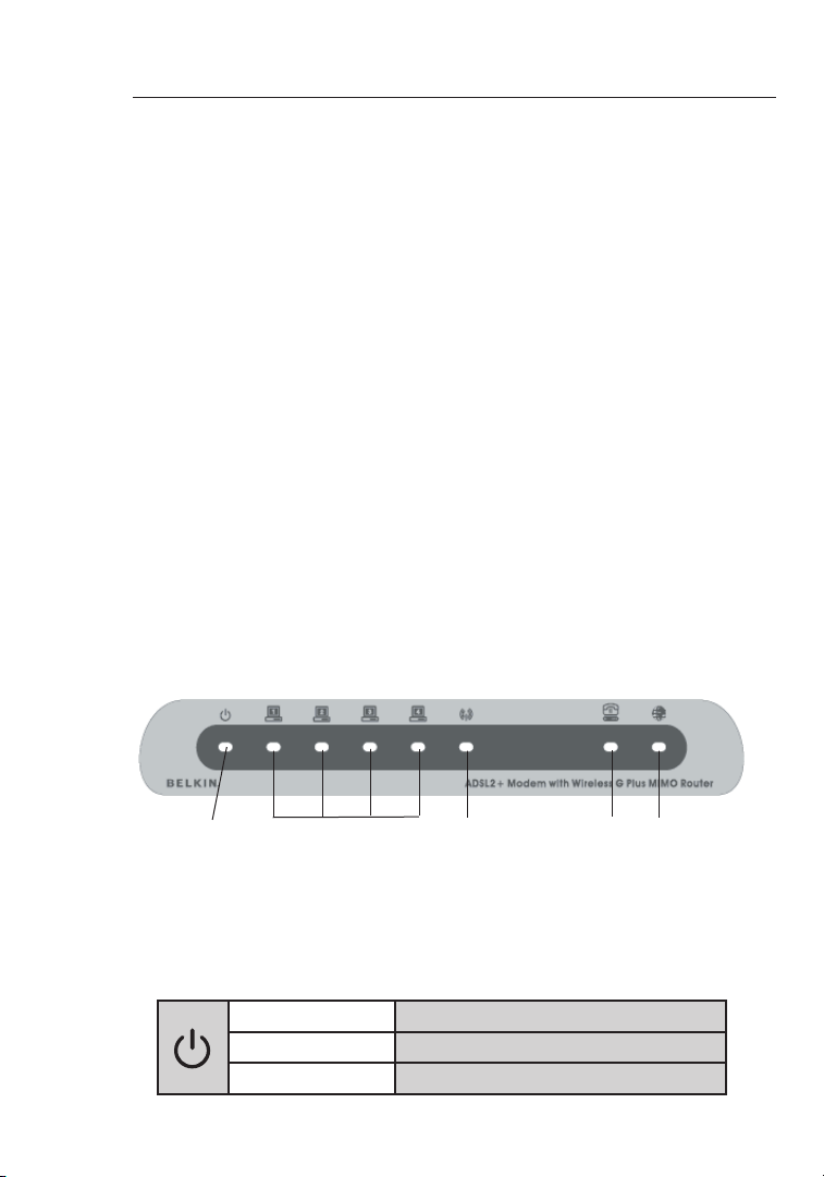
The Network Status Display
The Router has been designed to be placed on a desktop. All of the
cab les exit from the rear of t he Router for better organization and
uti lity. The Network Status Display i s easily visible on the FRONT of
the Router to provide you with information ab out network activity
and status. See the Network Status Display Gu ide for more detailed
inf ormation.
Front Panel
1. Power LED
Whe n you ap ply power to the Ro uter or restart it, a short period of time
ela pses while the Router boots up. When the Router ha s completely
boo ted up, the Power LED becomes a GREEN light, indic ating the
Rou ter is r eady for use.
OFF Route r is OFF
Green Route r is ON
Red Route r faile d to start
(1)
(4)
(3)
(5)
(2)
Page 11
9
Knowing your Router
9
section
2
1
3
4
5
6
7
8
9
10
12
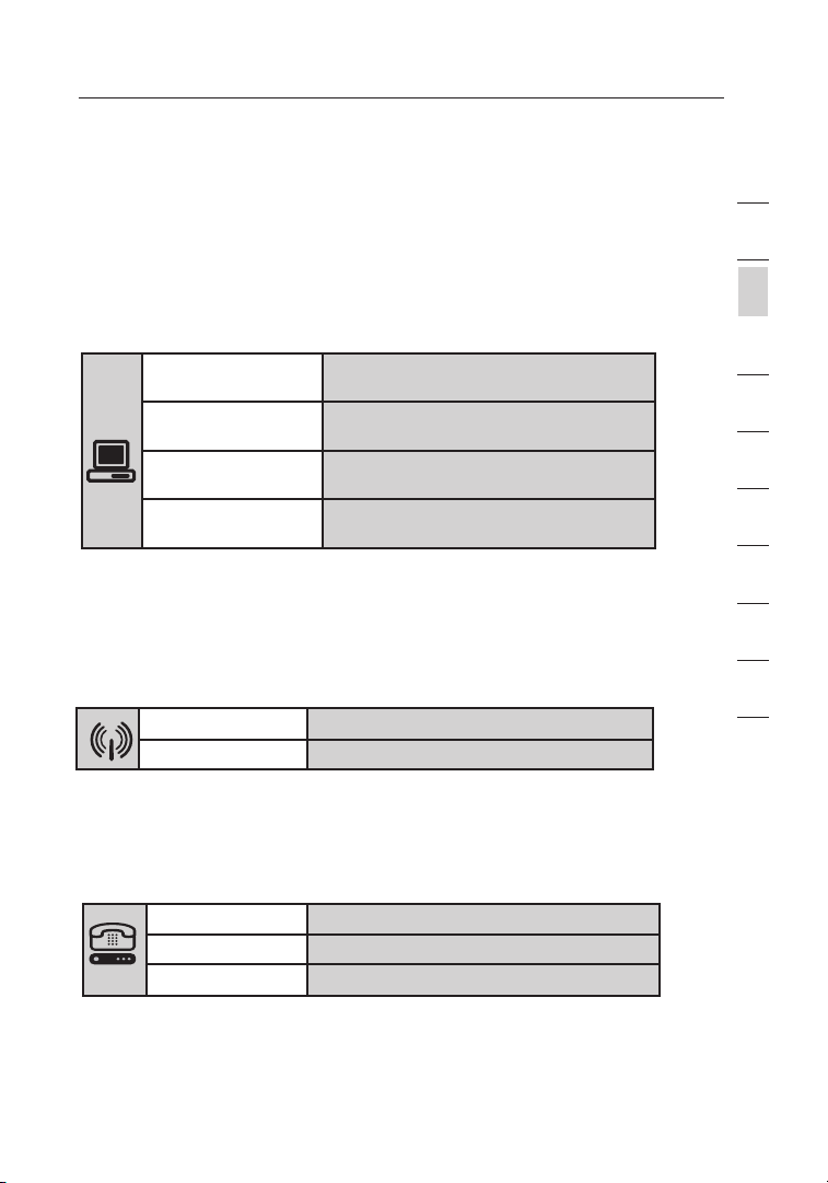
2. LAN Status LEDs
The se LAN S tatus LEDs are labeled 1–4 and correspond to the
num bered ports on the rear of the Router. When a computer is properly
con nected to one of the LAN po rts on t he rear of the R outer, the LED
wil l light. Solid GREEN means a computer or a network -enabled device
is connected. When informatio n is bei ng sent over the port, the LED
bli nks rapidly. ORANGE indica tes a 10 Base-T connecti on.
3. WLAN Status LED
The WLAN St atus LED is solid G REEN when you enable the wirele ss
LAN function. It flashes when the Router is transmitting or receiving
dat a wirelessly.
4. ADSL LED
The ADSL LE D flashes GREEN during negotiation with your ISP. It stays
GRE EN when the Router is connected properly t o your A DSL service.
Orang e Ethe rnet li nk is up an d 10Base-T
devic e conne cted
Orang e - blink ing 10B ase-T d evice i s trans mitti ng or
recei ving da ta
Green Ethe rnet link is up and 10 0Base -T
devic e is conn ected
Green - b linki ng 100Base-T devi ce is tra nsmit ting or
recei ving da ta
Green WLAN i s up and connected
Green - b linki ng Trans mitti ng or rec eivin g data
OFF No ADSL connection
Green - blinking Negotiating connection
Green ADSL link is up and conne cte d
Page 12
Knowing your Router
1110
5. Internet LED
The Internet LED shows you when the Router is connect ed to th e
Int ernet. When the LED is OFF, the Router is NOT connected to the
Int ernet. When the LED is solid GREEN, the Router is connected t o
the Internet. When the LED is blinking, the Router is transmitting or
rec eiving data from the Internet.
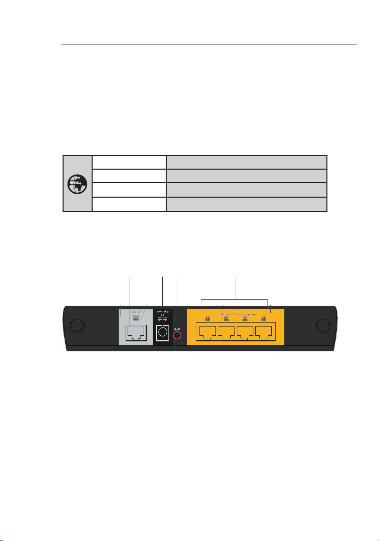
Back Panel
6. DSL Line
Thi s port i s for co nnection to your ADSL. Connect you r ADSL t o this
por t.
7. Ethernet Ports
The Ethernet ports are RJ45, 10/100 auto-negotiation . The ports are
lab eled 1 t hrough 4. These ports correspond t o the nu mbered LEDs on
the front o f the Ro uter. Connect your network -enabled computers or
any networking devices to one of these ports.
OFF No Intern et connection
Green Connected to the Internet
Green - blinking Transmitting or receiving data
Red Failed to connect to the Internet
(7)
(8)(9)
(6)
Page 13

11
Knowing your Router
11
section
2
1
3
4
5
6
7
8
9
10
12
8. Reset Button
The “Reset” button is used in rare cases when the Router may function
imp roperly. Resett ing the Rou ter will restore the Router’s norm al
ope ration while maintaining t he programmed settings. Yo u can al so
res tore the factory default settings by using the “Reset” button. Use
the restore option in instances where you may have fo rgotten your
cus tom password.
a. Res etting the Router
Push and hold the “Reset” button for one seco nd, then
rel ease it. When the “Power/Ready” li ght becomes solid
aga in, the reset is complete.
b. Re sto ring the Factory Defaul ts
Press and hold the “Reset” button for at leas t five s eco nds,
the n release it. When the “Power/Read y” light becomes solid
aga in, the restore is complete.
9. Power Plug
Con nect the included DC power supply to this inlet. U sing the wr ong
typ e of pow er adapter may cause damage to your Router .
Page 14

Connecting and Configuring your Router
1312
Verify the contents of your box. You should have the following:
• Bel kin Wireless G Plus MIMO ADSL2+ Modem Rout er
• RJ1 1 Telephone Cord
• RJ4 5 Ethernet Networking Cabl e
• Pow er Supply
• Bel kin Setup Assistant Softwa re CD
• Use r Manual
Setup Assistant
Bel kin has provided our Setup Assista nt software to make installing
you r Router a simple and easy task. You can use it to get your
Rou ter up a nd running in minutes. The Setup Assistant requires that
you r Windows 2000 ,XP or Vista computer be connected directly to
you r ADSL a nd that the Internet connection is active and work ing
at the time of inst allation. If it is not, you must use the “Alternate
Set up Method” section of this User Manual to configure your Router.
Add itionally, if you are using an operating s ystem other than Windows
200 0,XP, or Mac OS X you mu st set up the Route r using the “Alternate
Set up Method” section of this User Manual.
Step 1A: Hardware Connections – Follow the Quick Installation
Guide (QIG)
Brand-New Setup
Fol low these steps if you are not replacing an existi ng modem. I f you
are replacing an existing modem, skip to the next sec tion, “Replacing
an Existing Modem or Modem Router”, starting on page 13
1A.1 Unpack your new Router from the box and place i t next to your
com puter. Raise the Router’s antennas.
1A.2 Retrieve the yellow RJ4 5 cable that was included with your
Rou ter. First, connect one end to any yellow port lab eled “Wired
Com puters” on the back of your Router. Then, connect the other
end to the networking port on the back of your computer.
1A.3 Retrieve the included g ray RJ11 phone cord. Connect one end
to the gray port la beled “DSL” on the back of your Router. Then
con nect the other end to your ADSL connection (either a wall jac k
or an ADSL splitter).
Page 15

13
Connecting and Configuring your Router
13
section
2
1
3
4
5
6
7
8
9
10
12
Note: Some ADSL connections require a microfilter. Your ADSL provider
can tell you if you need one. Belkin includes a microfilter in regions
known to use them. You may or may not have received one in your box.
1A. 4 Plug your Router’s power supply into the black port labeled
“Po wer” on the back of your Router . Wait 30 secon ds for t he
Rou ter to s tart up. Look at th e front panel of the Router. Make
sur e one of the “LA N” and t he “POWER” LED’s are both lit up. If
the y are no t, recheck your connection s.
Step 1B: Replacing an Existing Modem or Modem Router
Fol low these steps if you currently have a modem or a modem router
tha t you wi ll be re placing with your new Router.
1B.1 Unpack your new Router from the box and place i t next to
you r old mo dem. Raise the Router’s antennas. Unplug your old
mod em’s power cord.
1B.2 Locate the cable that connects your old modem to y our
com puter. Unplug that cable from your old mod em, and plug it
int o any ye llow port labeled “Wired Computers” on the back of
you r new Ro uter.
1B.3 Locate the cable that connects your old modem to t he ADSL wall
jac k. Unplug it from your old modem and then connect it to the
gra y port l abeled “DSL” on the back of your Router.
1B.4 Plug your Router’s powe r supply into the black port labeled
“Po wer” on the back of your Ro uter.
1B.5 Wait 30 seconds for the Router to start up. Loo k at the front
pan el on th e Router. Make sure one of the “LAN” and the
“PO WER” icons are lit. If they are not, recheck your connections.
Step 2: Set Up the Router – Run the Setup Assistant Software
2.1 Shut down any progr ams that are running on your computer at this
tim e. Turn off any firewall or Intern et- connection-sharing software
on your com puter.
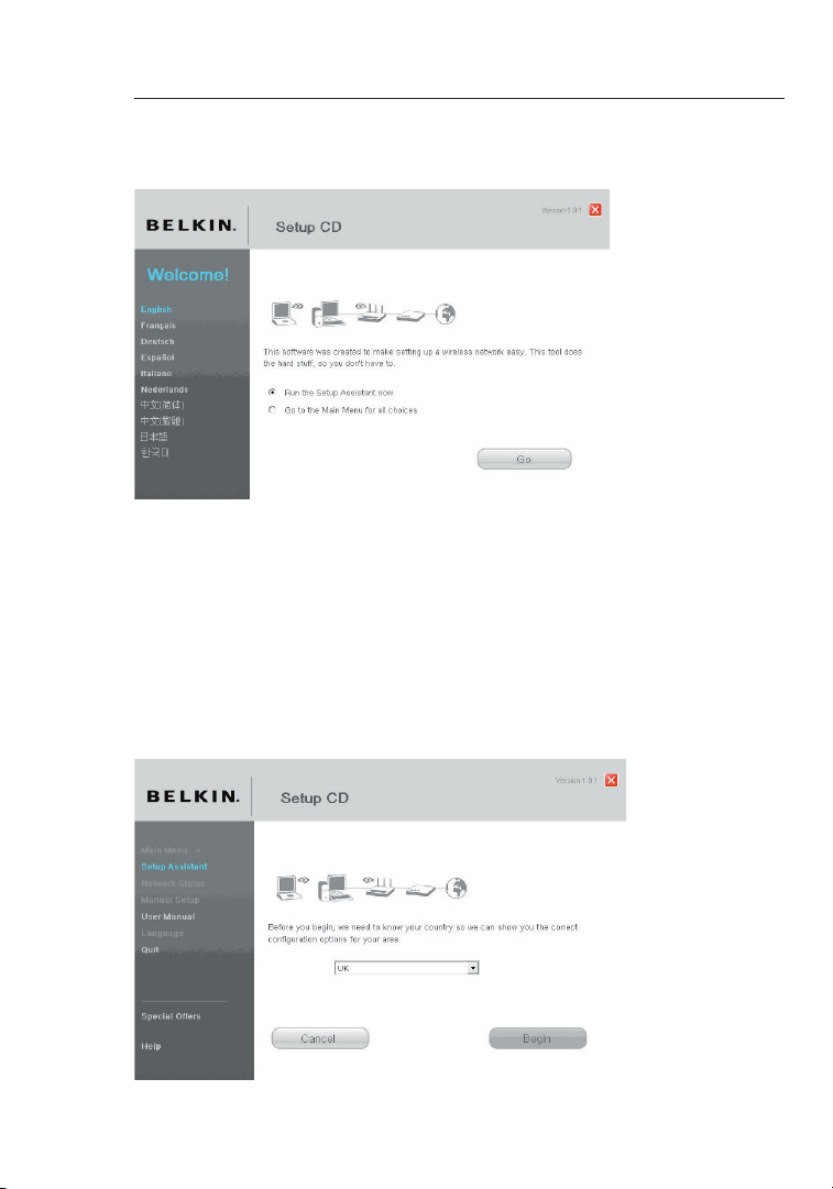
2.2 Insert the CD into your com puter. The Setup Assistant will
aut omatically appe ar on your computer’s screen withi n 15
sec onds. Click on “Go” to run the Setup Assistant. Fo llow the
ins tructions there .
Page 16
Connecting and Configuring your Router
1514
Note for Windows Users: If the Setup Assistant does not sta rt up
aut omatically, sel ect your CD -ROM drive from “My Computer” and
dou ble-click on the file named “Setup Assistant” to start the Setup
Ass istant.
NOTE TO MAC® USERS: Doub le-click on the “Easy Install” ico n to sta rt
the Setup A ssistant. Then, follow the prompts to complete the setup.
2.3 Select Coun try. Select your country from the drop-down box.
Cli ck “Begin” to continue.
Page 17
15
Connecting and Configuring your Router
15
section
2
1
3
4
5
6
7
8
9
10
12
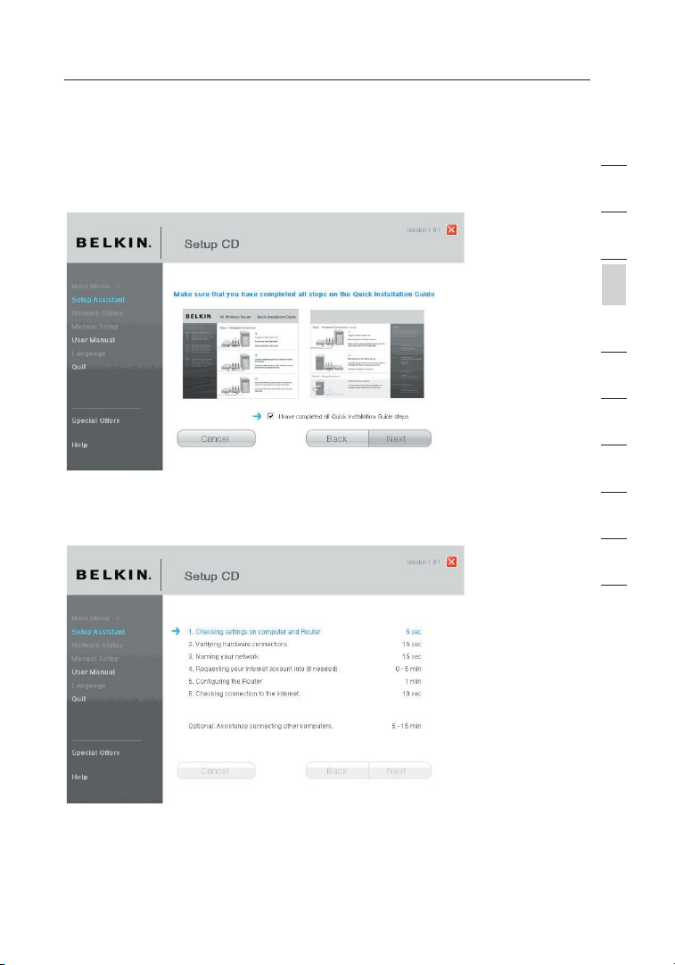
2.4 Confirmatio n Screen. Verify that you have completed a ll QIG s teps
by checking the box to the rig ht of th e arrow. Click “Next” to
con tinue.
2.5 Progress S creen. Setup Assistant wil l show y ou a pro gress screen
eac h time a step in the set up has been completed.
Page 18
Connecting and Configuring your Router
1716
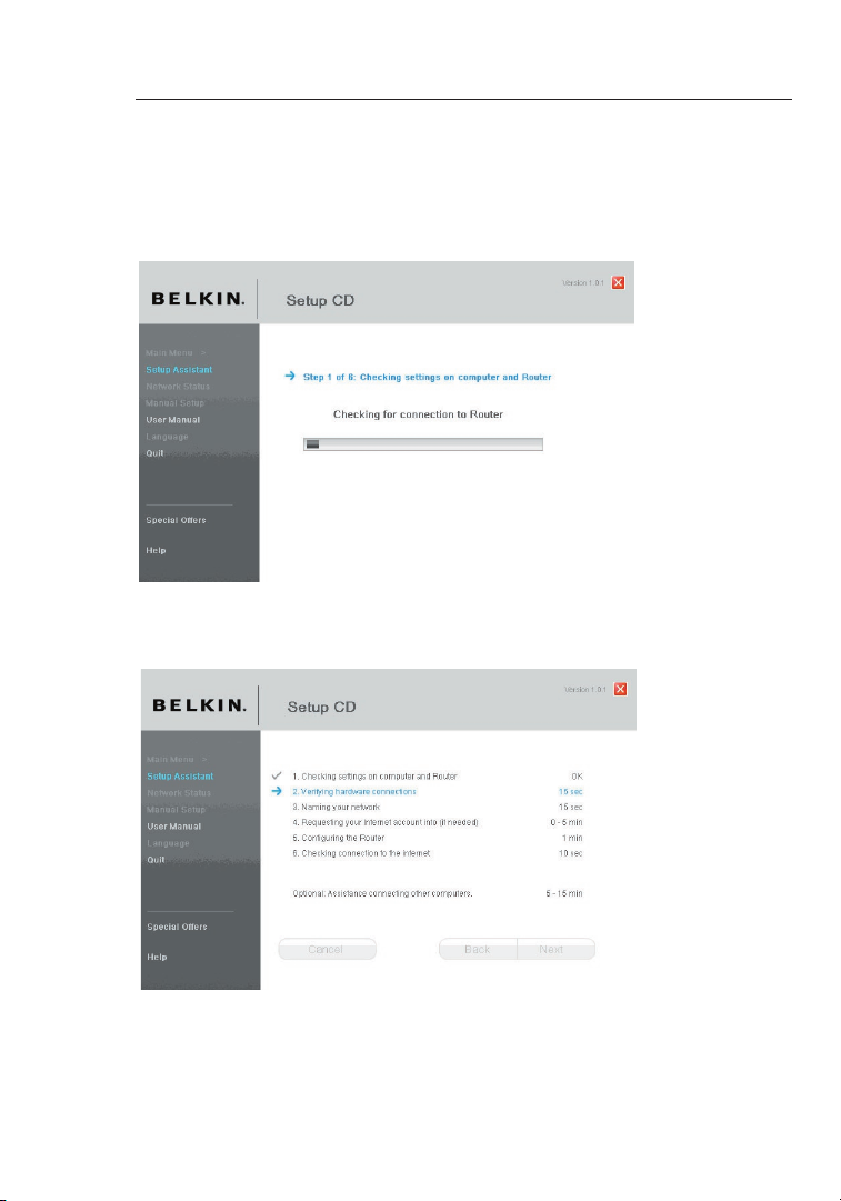
2.6 Checking S ettings. The Setup Assi sta nt will now examine your
com puter’s network settings a nd gather information n eed ed to
com plete the Router’s connect ion to t he Internet.
2.7 Verifying Hardware Connec tions. The Setup Assistant will no w
ver ify your hardware connecti on.
Page 19
17
Connecting and Configuring your Router
17
section
2
1
3
4
5
6
7
8
9
10
12
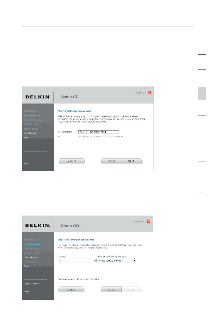
2.8 Naming you r Wireless Network. The Setup Assi stant will display the
def ault wireless network name or Serv ice Set Identifier (SSID). This
is the name of your wireless n etwork to which your computers or
dev ices with wireless network adapters will connect. You can either
use the def ault or change it t o something unique. Wri te down thi s
nam e for fu ture reference. Click “Nex t” to co ntinue.
2.9 Requesting Internet Accou nt Info (if needed). If your Internet
acc ount requires a login and password , you wi ll be pr ompted with
a screen si milar to the illustration below. S elect your country or ISP
fro m the dr op-down boxes.
Page 20
Connecting and Configuring your Router
1918
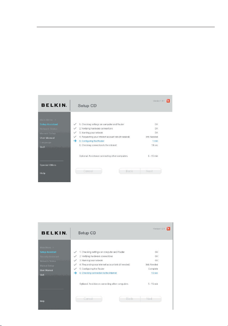
2.10 Configuring the Router. The Setup Assistant will now conf igure
you r Router by sending data to the Router and restart ing it. Wai t
for the on- screen instruction s.
Note: Do not disconnect any cab le or po wer off the Router while the
Rou ter is r ebooting. Doing so will render you r Router inoperable.
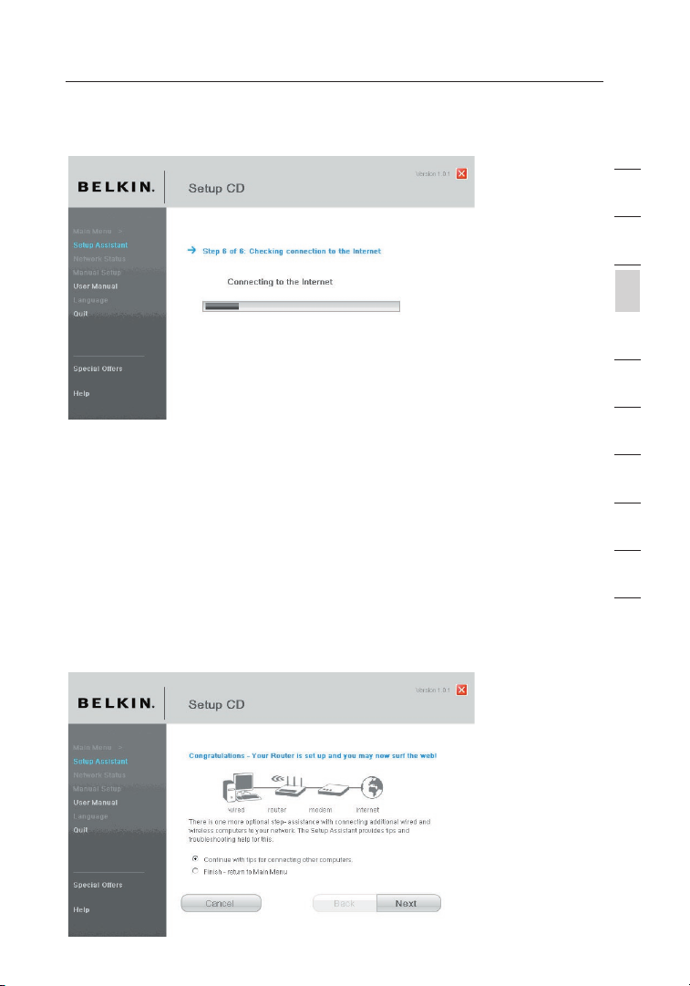
2.11 Checking Intern et Connection. We are almost do ne. The Set up
Ass istant will now check your connect ion to t he Internet.
Page 21
19
Connecting and Configuring your Router
19
section
2
1
3
4
5
6
7
8
9
10
12
Congr atula tions
You have fi nished installing your new Belkin Router. You will see the
Con gratulations sc ree n when y our Router can connect to the Internet.
You can beg in surfing by opening your browser and goi ng to an y
web site.
You can use the Set up Assistant to set up your other wired and
wir eless computers to connect to the Internet by clicking “Next”. If
you decide to add c omputers to your Router later, sel ect “Exit t he
Ass istant” and then click “Next”.
Page 22
Connecting and Configuring your Router
2120
Troubleshooting
If the Setu p Assistant is not able to connect to the Internet , you will see
the following screen. Follow the on-s creen instructi ons to go through
the troubleshootin g steps.
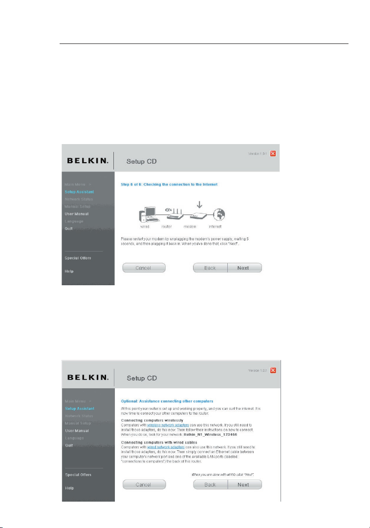
2.12 Optional: Assistance Connecting Other Computers
Thi s optional step will help you to connect additional wired and wireless
com puters to your network. Follow the on-screen instructions.
Page 23
21
Connecting and Configuring your Router
21
section
2
1
3
4
5
6
7
8
9
10
12
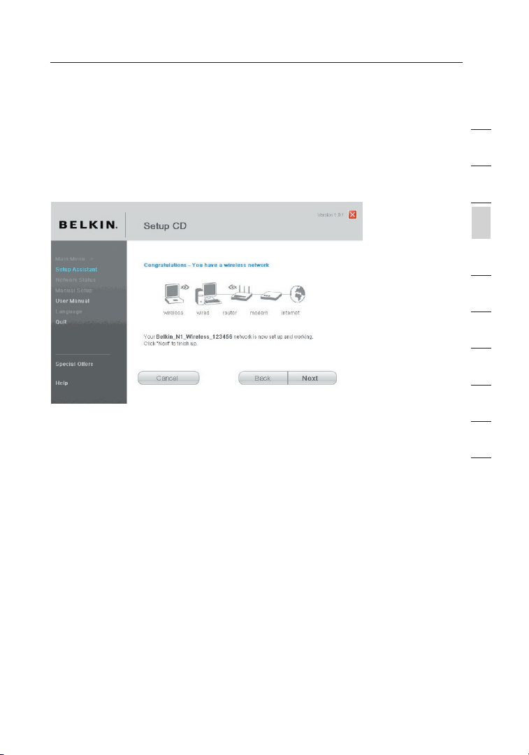
Congratulations
Onc e you ha ve verified that your other wired and wire less computers
are properly connected, your network is set u p and wo rking. You can
now surf th e Internet. Click “Next” to take you back to the main menu.
Page 24
Alternate Setup Method
2322
Step 1: Hardware Connections – Follow the Quick Installation
Guide
See the QIG or Step 1A/B: H ard ware Connection s from t he previous
sec tion.
Step 2: Set your Computer’s Network Settings to Work with a
DHCP Server
See the sec tion in this User M anual called “Manually Configuring
Net work Settings” for directi ons.
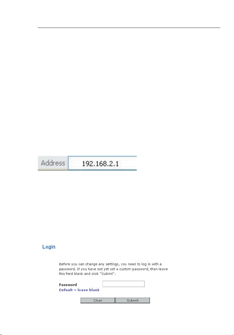
Step 3: Configuring the Router Using the Web-Based Advanced
User Interface
Usi ng your Internet browser, you can access t he Router’s Web-Based
Adv anced User Interface. In your brow ser, type “192.168.2.1” (d o
not type in anything else such as “http://” or “www”) . Then p res s the
“En ter” key.
Logging into the Router
You will se e the Ro uter’s home page in your browser window. T he
hom e page i s visible to any us er who w ants to see it. To make any
cha nges to the Router’s settings, you have to log in. Clicking t he
“Lo gin” button or clicking on any one of the links on the home page
wil l take y ou to th e login scr een. The Router ships with no password
ent ered. In the login screen, leave the passw ord blank and click the
“Su bmit” button to log in.
Page 25
23
23
section
2
1
3
4
5
6
7
8
9
10
12
Alternate Setup Method
Logging out of the Router
One computer at a t ime can log into th e Router for the purposes of
mak ing changes to the settings of the Router. Once a user has logged
in to make changes, there are two ways that the computer can be
log ged out. Clicking the “Logout” but ton will log the computer out. The
sec ond method is automatic. The login will ti me out a fter a s pec ified
per iod of t ime. The default login time-out is 10 minu tes. This c an be
cha nged from one to 99 minutes. For more information, see the se ction
in this man ual titled “Changing the Login Tim e-Out Setting”.
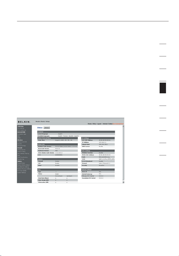
Understanding the Web-Based Advanced User Interface
The home pa ge is th e first pag e you wi ll see w hen you access the
Adv anced User Interface (UI). The hom e page s hows you a quick vi ew
of the Rout er’s status and settings. All adva nced setup pages can be
rea ched from this page.
1. Quick-Navigation Links
You can go directly to any of the Rout er’s advanced UI pages by
cli cking directly on these links. The links a re divided into logical
cat egories and grouped by tabs to make findin g a part icular setting
eas ier to f ind. Clicking on the purple header of each tab wil l show you
a short des cription of the tab’s function.
2. Home Button
The “Home” button is available in every page of the UI. Press ing this
but ton will take you back to t he home page.
Page 26

Alternate Setup Method
2524
3. Help Button
The “Help” button gives you access to the Router’s he lp pages. H elp
is also ava ilable on many pages by clicking “more inf o” next to certain
sec tions of each page.
4. Login/Logout Button
Thi s button enables you to log in and out of t he Router with the press
of one butt on. When you are lo gged into the Router, this butt on will
cha nge to r ead “Logout”. Logging into the Rou ter will take you t o a
sep arate login page where you will need to enter a password. Whe n
you are log ged into the Router, you can make changes to the settings.
Whe n you ar e finished making changes, you can log out of the Router
by clicking the “Logout” button. For more inf ormation about logging
int o the Ro uter, see the section called “Logg ing into the Router”.
5. Internet-Status Indicator
Thi s indicator is visible in all pages of the Router, indicating the
con nection status of the Router. When the ind icator says “Connected”
in blue, th e Router is connected to the Internet. Whe n the Ro ute r is not
con nected to the Internet, the indica tor will read “No Connection” in
RED . The in dicator is automatically u pdated when you make changes
to the sett ings of the Router.
6. Version Info
Sho ws the f irmware version, boot-code version, hardw are version, and
ser ial number of the Router.
7. LAN Settings
Sho ws you t he settings of the Local Area Network (LAN ) side o f the
Rou ter. Changes can be made to the settings by clicki ng on an y one
of the link s (IP Ad dress, Subnet Mask, DHCP Server) o r by cli cki ng the
“LA N” quick-naviga tio n link o n the le ft side of the s creen.
8. Internet Settings
Sho ws the s ettings of the Internet/WA N side o f the Ro uter that
con nects to the Internet. Changes to any of these set tings can b e
mad e by cli cking on the links or by cl icking on the “Internet /WA N”
qui ck-navigation l ink on the left sid e of the screen.
Page 27
25
Alternate Setup Method
25
section
2
1
3
4
5
6
7
8
9
10
12
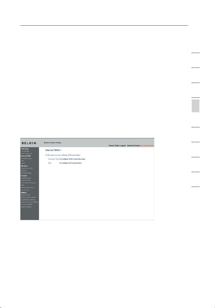
Step 4: Configuring your Router for Connection to your Internet
Service Provider (ISP)
The “Internet/WAN” tab is where you will set up your Router t o
con nect to your ISP. The Router is capable of connect ing to v irt ually
any ISP’s s ystem provided you have correctly configured the Router’s
set tings for your ISP’s connection ty pe. Your ISP connection settings
are provided to you by your IS P. To co nfigure the Router with the
set tings that your ISP gave you, click “Conne ction Type” (A ) on the
lef t side o f the sc reen. Select the connectio n type y ou use. If your ISP
gav e you DN S settings, clicking “DNS” (B) allows you to enter DNS
add ress entries for ISPs that require specific settings. Clicki ng “MAC
Add ress” (C) will let you clon e your c omputer’s MAC address or type
in a specif ic WAN M AC address, if required by your ISP. When you
hav e finished making settings , the “I nternet Status” indicator will read
“co nnection OK” if your Router is set up properly.
Connection Type
Fro m the “C onnection Type” page, you can sele ct one o f these fiv e
con nection types based on the instruc tion provided by your ISP:
• PPP oE
• PPP oA
• Dyn amic IP (1483 Bridged)
• Sta tic IP ( IPoA)
• Mod em Only (Disable Internet Sharing)
Page 28

Alternate Setup Method
2726
Sel ect the type of connection you use by clicking the radio b utt on (1)
nex t to you r connection type and then clickin g “Next” (2).
Setting your ISP Connection Type to PPPoE or PPPoA
PPP oE (Point-to-Po int Protocol over Ethernet ) is the standard m ethod
of connecting networked devic es. It r equires a user name and
pas sword to access the network of your ISP for connec ting to the
Int ernet. PPPoA (PPP over ATM) is similar to PPPoE, b ut is mo stl y
imp lemented in the UK. Select PPPoE or PPPoA and clic k “Next”. T hen
ent er the i nformation provide d by you r ISP, a nd click “Apply Changes”
to activate your settings.
(1)
(2)
(3)
(4)
(5)
(6)
(7)
(8)
(9)
Page 29

27
Alternate Setup Method
27
section
2
1
3
4
5
6
7
8
9
10
12
1. User N ame - Enter the user name (assigned by your ISP).
2. Pass word - Enter yo ur password (assigned by your ISP) .
3. Rety pe Pass word - Confirm the password (assigned by your ISP).
4. VPI/ VCI - Enter your Virtual Path Ident ifier (VPI) and Virtual Circuit
Ide ntifier. (VCI) parameter h ere (assigned by your ISP).
5. Enca psula tion - Select y our encapsulation type (su pplied by your
ISP ) to spe cify how to handle multiple protoc ols at t he ATM t ran sport
lay er.
VC-MU X: PP PoA Virtual Circuit Multip lexer (null encapsulation) allows
onl y one pr otocol running per virtual circuit with fewer overheads.
LLC: PPPoA Logical Link Control allo ws multiple protocols runn ing
ove r one vi rtual circuit (more overhe ad).
6. MTU – Enter th e MTU va lue for you r ISP.
7. Dial o n Demand - By selecting “ Dial on Demand”, your Router will
aut omatically conn ect to the Internet when a user opens up a web
bro wser.
8. Idle T ime (Minutes) - Enter the maxi mum idle time for the Internet
con nection. After this time has been exceeded, the connection will be
ter minated.
9. Use St atic Default Route – Check this box and use the static
IP address your ISP assigns for your line. Use this option on ly if
ins tructed by your ISP.
Cli ck “Apply Changes/Next” to save an d activate your settings. To
go back to the orig inal settings before savin g, click “Clear Changes”;
or click an y of the quick-navigation links fo r other options. Your new
set tings will not be saved unless you click “Apply Ch anges/Next”.
Page 30

Alternate Setup Method
2928
Setting your Connection Type to Dynamic IP (1483 Bridged)
Thi s connection method bridge s your n etwork and ISP’s network
tog ether. The Router will obtain an IP addres s automatically from your
ISP ’s DHCP server.
1. VPI/ VCI - Enter you r VPI an d VCI param eter here. These identi fiers
are assigned by your ISP.
2. Enca psula tion - Select L LC or VC MUX your ISP uses.
Cli ck “Apply Changes/Next” to save an d activate your settings. To
go back to the orig inal settings before savin g, click “Clear Changes”;
or click an y of the quick-navigation links fo r other options. Your new
set tings will not be saved unless you click “Apply Ch anges/Next”.
(1)
(2)
Page 31

29
Alternate Setup Method
29
section
2
1
3
4
5
6
7
8
9
10
12
Setting your ISP Connection Type to Static IP (IPoA)
Thi s connection type is also called “Classical IP over ATM” or “ CLIP”,
whi ch comprises a fixed IP address that your ISP prov ides for yo ur
Rou ter to c onnect to the Internet.
1. WAN IP Address – Enter an IP address as signed by your ISP for the
Rou ter WAN interface.
2. WAN Su bnet Mask - Enter a subnet mas k assigned by your ISP.
3. Defa ult Gat eway - Enter a default gat eway IP address. If the Router
can not find the destination address w ithin its local network, it will
for ward the packets to the default gateway as signed by your ISP.
4. VPI/ VCI - Enter your VPI and VCI parameter here . These identifiers
are assigned by your ISP.
5. Enca psula tion - Select L LC or VC MUX your ISP uses.
Cli ck “Apply Changes/Next” to save an d activate your settings. To
go back to the orig inal settings before savin g, click “Clear Changes”;
or click an y of the quick-navigation links fo r other options. Your new
set tings will not be saved unless you click “Apply Ch anges/Next”.
Setting your Connection Type to Modem Only (Disable Internet
Sharing)
In this mod e, the R outer simply acts as a bridge passing pack ets
acr oss the DSL port. It requires additional s oftware to be installed on
you r computers in order to access the Interne t.
(1)
(2)
(3)
(4)
(5)
Page 32

Alternate Setup Method
3130
1. VPI/ VCI - Enter your VPI and VCI parameter here (assigned by your ISP).
2. Enca psula tion - Select L LC or VC MUX your ISP uses.
Cli ck “Apply Changes” to save and activate yo ur settings. To go back
to the orig inal settings before savin g, click “Clear Changes”; or click
any of the quick-navigation links for other o ptions. Your new settings
wil l not be saved u nless you c lick “Apply Changes/Next”.
Setting Custom Domain Name Server (DNS) Settings
A “Domain Name Server” is a server located on the Internet that translates
Universal Resource Locaters (URLs) like “www.belkin.com” to IP
addresses. Many Internet Service Providers (ISPs) do not require you to
enter this information into the Router. The “Automatic from ISP” box (1)
should be checked if your ISP did not give you a specific DNS address.
If you are using a static IP connection type, then you may need to enter
a specific DNS address and secondary DNS address for your connection
to work properly. If your connection type is dynamic or PPPoE, it is likely
that you do not have to enter a DNS address. Leave the “Automatic
from ISP” box checked. To enter the DNS address settings, uncheck
the “Automatic from ISP” box and enter your DNS entries in the spaces
provided. Click “Apply Changes” (2) to save the settings.
(1)
(2)
(1)
(2)
Page 33

31
Alternate Setup Method
31
section
2
1
3
4
5
6
7
8
9
10
12
Using Dynamic DNS
The Dynamic DNS service allows you to create an alias dynamic IP
add ress to a static host name in any o f the ma ny domains DynDNS.org
off ers, allowing your network computers to be more easily accessed
fro m various locations on the Interne t. DynDNS.org provides this
ser vice, for up to five host n ames, free to the Internet comm uni ty.
The Dynamic DNS
SM
service is ideal f or a hom e website, file server, or
to make it easy to access y our home PC and sto red files while you’re
at work. Us ing the service can ensure that your host name alw ays
poi nts to y our IP a ddress, no matter how often your ISP chang es it.
Whe n your I P address changes, your friends an d associates can always
loc ate you by visiting yourname.dyndns.org instead.
To register free for your Dynamic DNS host name, plea se visit
http: //www .dynd ns.or g.
Setting up the Router’s Dynamic DNS Update Client
You must re gister with DynDNS.org’s f ree update service before using
thi s feature. Once you have your registration, follow the directions
bel ow.
1. Select “DynDNS.org” from the drop-down b ox. Click “Apply
Cha nges”.
2. Enter your DynDNS.org user name i n the “U ser Name” field (1).
3. Enter your DynDNS.org password in the “Password” field ( 2).
4. Enter the DynD NS.org domain name you set up with DynDNS. org in
the “Domain Name” field ( 3).
5. Click “Apply Changes” to update y our IP a ddress.
(1)
(2)
(3)
(4)
Page 34

Alternate Setup Method
3332
Whe never your IP address assigned by your ISP changes, the Router
wil l automatically update Dyn DNS.org’s serve rs with you r new
IP address. You can also do th is manually by clicking the “Ap ply
Cha nges” button ( 4)
.
(1)
(2)
(3)
(4)
Page 35

33
Using the Web-Based Advanced User Interface
33
section
2
1
3
4
5
6
7
8
9
10
12
Using the Web-Based Advanced User Interface
Usi ng your Internet browser, you can access t he Router’s Web-Based
Adv anced User Interface. In your brow ser, type “192.168.2.1” (d o not
typ e in any thing else such as “http://” or “www”) the n press the “Enter”
key .
You will se e the Ro uter’s home page in your browser window.
Viewing the LAN Settings
Cli cking on the header of the LAN tab (1) will take yo u to the LAN tab ’s
hea der page. A quick description of the funct ions can be found h ere.
To view the settings or make c hanges to any of the LAN settings, click
on “LAN Set tings” (2) or to view the list of connected computers, click
on “DHCP cl ient list” (3)
.
Page 36

Using the Web-Based Advanced User Interface
3534
Changing LAN Settings
All settings for the internal LAN setup of the Router can be viewed and
cha nged here.
1. IP Add ress
The “IP add ress” is the internal IP address of the Router. Th e default
IP address is “192.168.2.1”. To acces s the ad vanced setup interface,
typ e this I P address into the address bar of your browser. Th is address
can be chan ged if n eeded. To c hange the IP address, type in the new
IP address and click “Apply Changes”. The IP address you choose
sho uld be a non-routable IP. Examples of a non-routable IP are:
192 .168.x.x (where x is anything betw een 0 an d 255)
10. x.x.x (where x is anything between 0 and 255)
2. Subn et Mask
The re is no need to change the subnet mask. This is a unique,
adv anced feature of your Belkin Route r. It is possible to change the
sub net mask if necessary; however, do NOT mak e changes to the
sub net mask unless you have a specific reason to do so. The default
set ting is “255.255.255.0”.
3. DHCP S erver
The DHCP se rver function makes settin g up a network v ery easy
by assigning IP addresses to each computer on the net work
aut omatically. The default se tting is “On”. The DHCP server can be
tur ned OFF if necessary; however, in order to do so you must manually
set a stati c IP add ress for ea ch computer on your network. To turn off
the DHCP se rver, select “Off” and click “Appl y Changes”.
Page 37

35
Using the Web-Based Advanced User Interface
35
section
2
1
3
4
5
6
7
8
9
10
12
4. IP Poo l
The range o f IP add resses set aside for dynamic assig nment to th e
com puters on your network. The defaul t is 2–1 00 (99 c omputers). If
you want to change this number, you can do so by entering a new
sta rting and ending IP address and clicking o n “Apply Changes”. The
DHC P server can assign 100 IP addresses autom atically. This means
tha t you ca nnot specify an IP address pool larger tha n 100 co mpu ters.
For example, starting at 50 means you have to end at 150 or lower so
as not to exceed th e 100-client limit. The starting I P address m ust be
low er in nu mber than the ending IP address.
5. Leas e Time
The length of time the DHCP se rver will reserve the IP addres s for
eac h computer. We recommend that you leave th e lease time set to
“Fo rever”. The default settin g is “Fo rever”, meaning that any time
a computer is assigned an IP a ddress by the DHCP server, the IP
add ress will not change for that particular c omputer. Setting lease
tim es for s horter intervals such as one day or one hour frees IP
add resses after the specified period of time. This also means that a
par ticular compute r’s IP addr ess may change over time. If you have set
any of the other ad vanced features of the Router such as DMZ or client
IP filters, these are dependent on the IP address. Fo r this r eas on, you
wil l not wa nt the I P address t o change.
6. Loca l Domai n Name
The default setting is “Belkin”. You can set a local domain n ame
(ne twork name) for your network. Ther e is no need to change t his
set ting unless you have a specific advanced n eed to d o so. Yo u can
nam e the ne twork anything you want such as “MY NETWOR K”.
Viewing the DHCP Client List Page
You can vie w a list of the computers ( known as clients), whic h are
con nected to your network. You are able to view the IP addres s (1) of
the computer, the host name (2) (if th e computer has been assigned
one ), and t he MAC a ddress (3) of the computer’s network interfac e
car d (NIC). Pressing the “Refresh” (4) button will up dat e the li st. If
the re have been any changes, the list will be updated .
Page 38

Using the Web-Based Advanced User Interface
3736
Configuring the Wireless Network Settings
The “Wireless” tab lets you make changes to the wirel ess network
set tings. From this tab you can make changes to the wireless net work
nam e or Ser vice Set Identifier (SSID) , operating channel, encry ption
sec urity settings, and config ure the Router to be used as an acc ess
poi nt.
Wi-Fi® Multimedia (WMM®) Settings
Ena bling the WMM allows you to prioritize the data pa ckets of yo ur
net work. The prioritization c ategories are voice, vi deo , best e ffort,
and background. A WMM-enabled device delivers schedu led access.
It reserves network resources based o n the 80 2.1d tags of Wi-Fi
mul timedia applica tio ns.
Voi ce 6,7 Hig hest
Low est
Vid eo 4,5
Bes t Effort 0,3
Bac kground 1,2
Page 39

37
Using the Web-Based Advanced User Interface
37
section
2
1
3
4
5
6
7
8
9
10
12
Changing the Wireless Network Name (SSID)
To identify your wireless network, a name cal led the SSID is use d.
The SSID is your ne twork name. The default network na me of th e
Rou ter is “ Belkin Wireless G Plus MIMO”. Your network name will look
som ething like “Belkin_G Plus _MIMO_ADSL”. Yo u can ch ang e this t o
any thing you choose, or you can leave it unchanged. K eep in m ind , if
you decide to change your wireless network na me, and there are o ther
wir eless networks operating i n your a rea, your network name needs to
be different from other wireless netw orks that may be operating in your
are a. To ch ange the SSID, type in the SSID that you want to use in the
SSI D field (1) and click “Appl y Changes” (2). The change is immediate.
If you make a chang e to the SSID, your wireless-equip ped computers
may also ne ed to be reconfigured to connect to your new netwo rk
nam e. Refer to the documentation of your wire less network adapter for
inf ormation on making this change.
Note: Please periodically check for new Router firmware u pdates
fro m the “U tilities > Firmware update ” page. Newer firmware can fix
pro blems, add wireless featur es, and/or improve wire les s performance
(se e page 5 1).
Changing the Wireless Channel
The re are a number of operating channels from which y ou can
cho ose—in the United Kingdom (and mos t of Eur ope) and Australia,
the re are 1 3. In ot her countries, there are other cha nnel requirements.
You r Router is configured to operate on the proper ch annels for the
cou ntry in which you reside. The channel can be chang ed if ne ede d. If
the re are o ther wireless networks ope rating in your area, your network
sho uld be s et to op erate on a channel that is different than the other
wir eless networks.
Page 40

Using the Web-Based Advanced User Interface
3938
Using the Wireless Mode Switch
Thi s switch allows you to set the Router’s wireless m odes. There are
sev eral modes.
Note: Some modes may require fi rmware updates to be enabled.
1) 802.11g + 802.11b
Set ting the Router to this mode will allow 802.11g- a nd 802.11bcom pliant devices to join the network . 802.11g devices will operate at
the 802.11b speed only
2) 802. 11g onl y
Set ting the Router to this mode will allow only 802.1 1g-compliant
dev ices to join the network, keeping out 802. 11b devices.
Using the Broadcast SSID Feature
Note:
This advan ced feature should be employed by advanced users
onl y. For s ecurity, you can choose not to broadcast y our network’s
SSI D. Doing so will keep your network name hidden fro m computers
tha t are sc anning for the presence of wireles s networks. To turn off
the broadcast of the SSID, remove the check mark from the box next
to “Broadcast SSID”, and then click “Apply Ch anges”. The change is
imm ediate. Each computer now needs to be set to conne ct to yo ur
spe cific SSID; an SSID of “ANY” will no longer be accepted. R efe r to
the documentation of your wireless ne twork adapter for informat ion on
mak ing this change.
Changing the Wireless Security Settings
You r Router is equipped with the latest secur ity standard called Wi-Fi
Pro tected Access™ 2 (WPA2™). It also supports the legacy security
sta ndard called Wired Equival ent Privacy (WEP). By default, wir eless
sec urity is disabled. To enable secur ity, you will need to determine
whi ch standard you want to use. To access the securit y settings, click
“Se curity” on the “Wireless” tab.
Page 41

39
Using the Web-Based Advanced User Interface
39
section
2
1
3
4
5
6
7
8
9
10
12
The Router features WPA2, which is the second generation of the WPA™bas ed 802.11i standard. It offers a higher le vel of w ireless security by
com bining advanced network au thentication an d stronger Advanced
Enc ryption Standar d (AES) enc ryption methods .
WPA2 Requirements
IMPORTANT:
In order to use WPA2 secur ity , all yo ur computers and
wir eless client adapters must be upgr aded with patches, driver, and cli ent
uti lity software that support ed WPA2. At the time of this User M anual’s
pub lication, a couple securit y patches are available , for free download,
fro m Microsoft
®
. These pat ches work only with the Windows XP operati ng
sys tem. Other operating syste ms are n ot supported at this time.
For Windows XP computers that do not have Service Pac k 2 (SP2 ), a file
fro m Microsoft called “Window s XP Sup port Patch for Wireless Protected
Acc ess (KB 826942)” is available for free dow nload at http://support.
mic rosoft.com/?kbid=826942
For Windows XP with Service Pack 2, Microsoft has rel eased a fre e
dow nload to update the wireless clien t components to support WPA2
(KB 893357). The update is available f rom: http://sup por t.microsoft.com/
def ault.aspx?scid=kb;en-us;8 93357
IMPORTANT: You also need to ensure that all your wireless cli ent cards/
ada pters support WPA2, and that you have down loaded and installed
the latest driver. Most of the Belkin wireles s cards have driver updates
ava ilable for download from the Belki n support site: www.belkin .com/
net working.
Page 42

Using the Web-Based Advanced User Interface
4140
Setting WPA/WPA2-Personal (PSK)
Lik e WPA se curity, WPA2 is available in both WPA2-Personal (PSK)
mod e and WP A2-Enterprise (RAD IUS) mode. Typically, W PA2 -Personal
(PS K) is th e mode t hat will be used in a home environment, while
WPA 2-Enterprise (R ADI US) is i mplemented in a busines s environment
whe re an ex ternal radius server distr ibutes the network key to the
cli ents automatica lly . This g uide will focus on WPA2-Personal ( PSK)
usa ge. Please refer to the User Manual for more infor mation about
wir eless security and differe nt types of wireless security.
1. After you’ve set up your Route r, go to the “Secur ity” page under
“Wi reless” and select “WPA/WP A2-Personal (PS K)” from th e “Security
Mod e” drop-down menu.
2. For “Authentic ation”, select “WPA-PSK”, “WPA2-PSK”, or “WPAPSK + WPA2- PSK”. This setting will have to be identic al on th e
wir eless clients that you set up. “WPA-PSK + WPA2-PSK” mode
wil l allow the Router to support clients runn ing either WPA or W PA2
sec urity.
3. For “Encryption Technique”, sele ct “TKIP”, “AES”, or “TKIP+AES”.
Thi s setting will have to be i dentical on the wireles s clients t hat you set
up.
4. Enter your pre-shared key (PSK). This can be from eight to 63
cha racters and can be letters, number s, or sy mbols. This same
key must be used on all of the wireles s clients that you set up. For
exa mple, your PSK might be something like: “S mith family network
key ”. Click “Apply Changes” to finish . You mu st now s et all w ire less
cli ents to match these settings.
Page 43

41
Using the Web-Based Advanced User Interface
41
section
2
1
3
4
5
6
7
8
9
10
12
IMPORTANT: Make sure your wireless computers are updated to work
wit h WPA2 a nd have the correct settings to get proper connection to
the Router.
Setting WPA Security
Note: To use WPA security, your wireless network cards must be
equ ipped with software that supports WPA. At the time this User
Man ual was published, a security patc h from M icrosoft is available for
fre e download. This patch works only with Win dows XP.
You r Router supports WPA-PSK (no serv er). WPA-PSK uses what is
kno wn as a pre-shared key as t he security key. A pre-shared k ey is
bas ically a password that is between eight an d 39 cha racters long. It
can be a combination of letters, numbers, or characters. Each client
use s the sa me key t o access th e network. Typically th is is th e mode
tha t will b e used i n a home environment.
Setting WPA-PSK
1. From the “Security Mod e” drop-down menu, select “WPA-PSK (no
ser ver)”.
2. For “Encryptio n Technique”, select “TKIP ” or “AE S”. This setting will
hav e to be identical on the cl ients that you set up.
3. Enter your pre-shared key. This c an be fr om eight to 39 c haracters
and can be letters, numbers, or symbols. This same ke y must b e used
on all of the clien ts that you set up.
4. Click “Apply Changes” to finish. You must now set all clients to
mat ch these settings.
Page 44

Using the Web-Based Advanced User Interface
4342
WPA-E nterp rise (R ADIUS ) is a con figuration wherein a radiu s server
dis tributes the keys to the clients automatically. This is typically us ed
in a busine ss environment.
Setting WPA-Enterprise (RADIUS) Settings
If your net work uses a radius server to distribute ke ys to th e clients,
use this se tting.
1. From the “Security Mod e” drop-down menu, select “WPA/WPA2—
Ent erprise (RADIUS )”.
2. Select “WPA-RA DIUS” in the “Authenticati on” field.
3. In the “Encryption Tec hnique” field, select “TKI P”. This setting will
hav e to be identical on the cl ients that you set up.
4. Enter the IP address of the radius server into th e “Radius Server”
fie lds.
5. Enter the radius key into the “Radius Key ” field.
6. Enter the key interval . Key in ter val is h ow often the keys are
dis tributed (in packets).
7. Click “Apply Changes” to finish. You must now set all clients to
mat ch these settings.
Page 45

43
Using the Web-Based Advanced User Interface
43
section
2
1
3
4
5
6
7
8
9
10
12
Setting WPA2-Enterprise (RADIUS) Settings
If your net work uses a radius server to distribute ke ys to th e clients,
use this se tting.
1. From the “Security Mod e” drop-down menu, select “WPA/WPA2—
Ent erprise (RADIUS )”.
2. Select “WPA2-R ADIUS” in the “Authenticat ion” field.
3. In the “Encryption Tec hnique” field, select “AES ”. This setting will
hav e to be identical on the cl ients that you set up.
4. Enter the IP address of the radius server into th e “Radius Server”
fie lds.
5. Enter the radius key into the “Radius Key ” field.
6. Enter the key interval . Key in ter val is h ow often the keys are
dis tributed (in packets).
7. Click “Apply Changes” to finish. You must now set all clients to
mat ch these settings.
Setting WEP Encryption
Note to M ac users: The “Passphrase” option will not operate with
App le
®
AirPort®. To config ure encryption for your Mac comput er, set
the encryption using the manual metho d described in the next section.
1. Select “128-bi t WEP” o r “64-bit W EP” from the drop-down menu.
2. After selectin g your W EP encryption mode, you can enter you WEP
key manually by typing in the hex WEP key manually, or you can type
a passphrase in the “PassPhrase” fiel d and cl ick “Generate” to create
a WEP key from the passphrase. Click “Apply Changes” to finish. You
mus t now se t all of your cl ien ts to ma tch these settings.
Page 46

Using the Web-Based Advanced User Interface
4544
3. Encryption in the Rout er is no w set. Each of your computers on
you r wireless network will now need to be configured with the sa me
pas sphrase. Refer to the documentation of your wireless network
ada pter for information on making thi s change.
Using a Hexadecimal Key
A hexadecimal key is a mixture of numbers and letters from A– F and
0–9 . 64-bit keys are 10 digits long and can be divided into five twodig it numbers. 128-bit keys are 26 digits lon g and ca n be div ide d into
13 two-digit numbers.
For instance:
AF 0F 4B C3 D4 = 64-bit key
C3 03 0F AF 0F 4B B 2 C3 D4 4B C3 D 4 E7 = 128-b it key
In the boxe s below, make up yo ur key b y writing in two characters
bet ween A–F and 0–9. You will use this key to program the encryption
set tings on your Router and your wireless com puters.
Note to M ac users: Original Apple A irPort products support 64 -bit
enc ryption only. Apple AirPor t 2 prod ucts can support 64-bit or 128-bit
enc ryption. Please check your product to see which version you are
usi ng. If y ou cannot configure your network w ith 128-bit encryption, tr y
64- bit encryption.
Page 47

45
Using the Web-Based Advanced User Interface
45
section
2
1
3
4
5
6
7
8
9
10
12
Wireless Bridge
Wir eless bridging or Wireless Distribution System (W DS) is used to
con nect wireless routers and access p oints (APs) together to extend a
net work.
Cli ck on th e drop-down menu next to “Bridge Mode” to select e ith er:
Disab led: To di sable wireless bridging (d efault).
Manua l: To enter the wireless MAC address(es ) of the APs to which to
bri dge, manually.
1. Wireless chann els must match between the Router and AP.
2. Security setti ngs (WEP) must match between the Router an d AP.
3. If MAC filtering is enabled, t he user mus t be sur e to add the WLA N
MAC address(es) of the Router/AP in order to allow co mmunication with
eac h other.
4. If using a network protected b y WPA, the SSID on both APs must be
the same.
Page 48

Using the Web-Based Advanced User Interface
4746
Configuring the Firewall
You r Router is equipped with a firewall that will pro tect your n etwork
fro m a wide array o f common ha cker attacks including:
• IP Spoofing
• Lan d Attack Ping of Death (PoD)
• Den ial of S ervice (DoS)
• IP with zer o length
• Smu rf Attack
• TCP Null Sc an
• SYN flood
• UDP flooding
• Tea r Drop A ttack
• ICM P defect
• RIP defect
• Fra gment flooding
The firewall also masks common ports that are frequently used to
att ack networks. These ports appear t o be “st ealth” meaning that for all
int ents and purposes, they do not exist to a would-be hacker. Yo u can
tur n the fi rewall function off if needed; how ever, it is recommended that
you leave t he firewall enabled. Disab ling the firewall protecti on will not
lea ve your network completely vulnerable to hacker attacks, but it is
rec ommended that you leave the firewa ll enabled.
Configuring Internal Forwarding Settings
The Virtual Servers function will all ow you t o route external (Internet )
cal ls for s ervices such as a w eb server (port 80), FTP server (Port 21),
or other ap plications through your Ro uter to your internal network.
Page 49

47
Using the Web-Based Advanced User Interface
47
section
2
1
3
4
5
6
7
8
9
10
12
Sin ce your internal computers are pro tected by a firewall, computers
out side your network (over the Intern et) cannot get to them because
the y cannot be “seen”. A list of common applications has been
pro vided in case you need to c onfigure the Virtual Se rver function for
a specific application. If your appli cation is not listed, you will need to
con tact the application vendo r to fin d out wh ich port settings you need.
Choosing an Application
Sel ect your application from the drop -down list. Click “Add”. The
set tings will be transferred to the next avai lable space in the screen.
Cli ck “Apply Changes” to save the setting for that ap plication. To
rem ove an a pplication, select the num ber of t he row t hat you wan t to
rem ove then click “Clear”.
Manually Entering Settings into the Virtual Server
To manually enter settings, enter the IP addr ess in t he space pr ovided
for the int ernal (server) machine, th e port(s) required to pass (use a
com ma between multiple ports) , select the port type (TCP or UDP),
and click “ Apply Changes”. You can only pass one port per int ern al IP
add ress. Opening ports in your firewa ll can p ose a se curity risk. You
can enable and disable settings very quickly. It is r ecommended that
you disable the settings when you are not using a specific ap pli cation.
Page 50

Using the Web-Based Advanced User Interface
4948
Setting Client IP Filters
The Router can be c onfigured to restrict acce ss to th e Internet, e-mail,
or other network servic es at sp ecific days and time s. Restriction can be
set for a single co mputer, a r ange of computers, or multiple com puters.
To restrict Internet access to a single compu ter for example, enter the
IP address of the c omputer you wish to restrict acces s to in the IP
fie lds (1). Next, ente r “80” i n both t he port fields (2). Select “Both” (3).
Sel ect “Block” (4). You can also select “Alwa ys” to b lock access all
of the time . Select the day to start o n top (5 ), the t ime to s tart on top
(6), the day to end on the bottom (7), and the time to stop (8) on the
bot tom. Select “Enable” (9). Click “Apply Cha nges”. The computer at
the IP addr ess you specified will now be blocked from Internet a ccess
at the time s you sp ecified. Note: Be sure y ou have selected the correct
tim e zone u nder “Utilities> System Se ttings> Time Zone”.
Setting MAC-Address Control
The MAC-address filter is a powerful security feature that allows you
to specify which computers are allowe d on the network. Any computer
att empting to access the network that is not specified in the fi lter list
wil l be den ied access. When you enable this feature, you must en ter a
nam e for th e user a nd the M AC address of each client on your network
to allow ne twork access. Next, click “Add” to save th e settings.
Page 51

49
Using the Web-Based Advanced User Interface
49
section
2
1
3
4
5
6
7
8
9
10
12
Enabling the Demilitarized Zone (DMZ)
The DMZ fea ture allows you to specify one computer on your ne two rk
to be place d outside of the fi rewall. This may be necessary i f the
fir ewall is causing problems with an application such as a game or
vid eo conferencing application. Use this feature on a temporary basis.
The computer in the DMZ is NOT protect ed from hacker attacks.
To put a computer i n the DM Z, enter th e last d igits of its IP address in
the IP fiel d and se lect “Enable”. Click “Appl y Changes” for the change
to take eff ect. If you are usi ng multiple static WAN IP addre sse s, it is
pos sible to select which WAN IP address the DMZ host will be directed
to. Type in the WAN IP addr ess you wis h the DM Z host t o direct to,
ent er the l ast two digits of t he IP ad dress of the DMZ host computer,
sel ect “Enable” and click “Apply Chan ges”.
Blocking an ICMP Ping
Com puter hackers use what is known as “pingin g” to fi nd potential
vic tims on the Internet. By pinging a specifi c IP add ress and re ceiving
a response from the IP address, a hacker can de ter mine that something
of interest might be there. The Router can be set up so it will not
res pond to an ICMP ping from t he outside. This height ens your
Rou ter’s security level.
Page 52

Using the Web-Based Advanced User Interface
5150
To turn off the pin g response, select “Block ICMP Pin g” (1 ) and click
“Ap ply Changes”. The Router will not respond to an IC MP ping.
Security Log
The security log shows detailed syste m-monitoring in for mation. Users
can click t he “Save” button to store the log as a text file for later
ref erence purposes . The “Refr esh” button refreshes t he page wit h any
new logs an d the “C lear” button clears the page of any existi ng logs.
Page 53

51
Using the Web-Based Advanced User Interface
51
section
2
1
3
4
5
6
7
8
9
10
12
Utilities
The “Utilities” screen lets you manag e different parameters of the Rout er
and perform certain administr ative functions .
Restarting the Router
Som etimes it may be necessary to restart or reboot th e Router if it begi ns
wor king improperly . Restarting or rebooting the Rout er will NOT delete
any of your configuration settings.
Restarting the Router to Restore Normal Operation
1. Click the “Res tart Router” button.
2. The following message will appear. Click “OK”.
Page 54

Using the Web-Based Advanced User Interface
5352
3. The following message will appear. Restarting th e Router can take
up to 60 seconds. I t is imp ort ant not to turn off the power to the
Rou ter during the restart.
4. A 60-second countdown will appear on the screen. When the
cou ntdown reaches zero, the Router wi ll be re started. The Router home
pag e should appear automatica lly. If not, type in the Router’s address
(de fault = 192.168.2.1) into the navi gation bar of your browser.
Restoring Factory Default Settings
Usi ng this option will restore all of the settings in the Rou ter to the
fac tory (default) settings. I t is rec ommended that you back up your
set tings before you restore all of the defaul ts.
1. Click the “Res tore Defaults” button.
2. The following message will appear. Click “OK”.
3. The following message will appear. Restoring the defaults includes
res tarting the Router. It can take up to 60 seconds. It is important not
to turn the power t o the Ro ute r off du ring the restart.
Page 55

53
Using the Web-Based Advanced User Interface
53
section
2
1
3
4
5
6
7
8
9
10
12
4. A 60-sec ond countdown will appear on the screen. W hen the
cou ntdown reaches zero, the Router’s defaults will be restored. The
Rou ter home page should appear automa tically. If it does not, type in
the Router’s address (default = 192.1 68.2.1) into the navigatio n bar of
you r browser.
Saving a Current Configuration
You can sav e your c urrent configurati on by us ing this feature. Saving
you r configuration will allow you to restore it later if your se ttings are
los t or cha nged. It is recommended that you back up your curr ent
con figuration befo re performing a firmware update.
1. Click “Save”. A window called “Fi le Download” will open. Click
“Sa ve”.
2. A window will open that allows you to select the location where you
wan t to sav e the co nfiguration file. Select a location. You can name
the file an ything you want, or use the default name “Config”. Be sure
to name the file so you can locate it yourself later. When you have
sel ected the location and name of the file, click “Sa ve”.
Page 56

Using the Web-Based Advanced User Interface
5554
3. When the save is complete, you will see the windo w below. Click
“Cl ose”.
The configuration is now saved.
Restoring a Previous Configuration
Thi s option will allow you to restore a previously sa ved configuration.
1. Click “Browse” . A wind ow will ope n that a llows you to select the
loc ation of the configuration file. A ll configuratio n files end with a “.bin”.
Loc ate the configuration file you wan t to res tore and double-click on it.
2. You will be asked if you want to continue. Click “OK”.
Page 57

55
Using the Web-Based Advanced User Interface
55
section
2
1
3
4
5
6
7
8
9
10
12
3. A reminder window will appear. It will ta ke up to 60 seco nds for the
con figuration rest ora tion to complete. Click “OK”.
4. A 60-second countdown will appear on the screen. When the
cou ntdown reaches zero, the Router’s configuration w ill be rest ored.
The Router’s home page should appear automatically. If not, type in
the Router’s address (default = 192.1 68.2.1) into the navigatio n bar of
you r browser.
Updating the Firmware
Fro m time t o time, Belkin may release new versions of the Rou ter ’s
fir mware. Firmware updates co ntain feature improvements and fixes to
pro blems that may have existed. When Belkin r eleases new firmware,
you can dow nload the firmware from the Belkin update website and
upd ate your Router’s firmware to the latest v ersion.
Checking for a New Version of Firmware
The “Check Firmware” (1) button allows you to instant ly check fo r a
new version of firmware. When you click the button, a new bro wse r
win dow will appear informing you that either no new f irmware is
ava ilable or that there is a n ew version available. I f a new version is
ava ilable, you will have the option to downlo ad it.
Downloading a New Version of Firmware
If you clic k the “C heck Firmware” button and a new version of
fir mware is available, you will see a screen similar to the o ne below:
Page 58

Using the Web-Based Advanced User Interface
5756
1. To download the new version of firmware, click “Download ”.
A window wi ll open that allows you to select the location whe re you
wan t to sav e the fi rmware file. Select a location. Yo u can na me the file
any thing you want, or use the default name. Be sure to locate the file in
a place whe re you c an locate i t yourself later. When you have selected
the location, click “Save”.
2. When the save is complete, you will see the follo wing window. Click
“Cl ose”.
3. The download of the firmware i s complete. To update the firmware ,
fol low the next steps in “Updating the Router ’s Firmware”.
Page 59

57
Using the Web-Based Advanced User Interface
57
section
2
1
3
4
5
6
7
8
9
10
12
Updating the Router’s Firmware
1. In the “Firmware Updat e” page, cl ick “Browse”. A window will ope n
tha t allows you to select the location of the firmwar e update fi le.
2. Browse to the firmware file yo u downloaded. Select the file by
dou ble-clicking on the file name.
The “Update Firmware” box will now display th e location and name of
the firmware file you just selected. Click “U pdate”.
3. You will be asked if you are sure you want to continue. Click “OK ”.
Page 60

Using the Web-Based Advanced User Interface
5958
4. You will see one more message. This messa ge tells you that the
Rou ter may not respond for as long as one minute as the firmware is
loa ded into the Router and the Router is rebooted. Cl ick “OK”.
5. A 60-second countdown will appear on the screen. When the
cou ntdown reaches zero, the Router fi rmware update will be complete.
The Router home page should appear automatically. If not, type in the
Rou ter’s address (default = 192.168.2.1) into the navigation ba r of you r
bro wser.
Changing System Settings
The “System Settings” page is where you can enter a new
adm inistrator pass wor d, set t he time zone, enable remote
man agement, and turn on and off the NAT function of the Route r.
Setting or Changing the Administrator Password
The Router ships with NO password entered. If you wis h to add a
pas sword for greater security , you ca n set a password here. Write
dow n your p assword and keep it in a sa fe place, as you will need it if
you need to log int o the Ro ute r in the future. It is a lso recommended
tha t you se t a pass word if you plan to use the remote management
fea ture of your Router.
Changing the Login Time-Out Setting
Page 61

59
Using the Web-Based Advanced User Interface
59
section
2
1
3
4
5
6
7
8
9
10
12
The login t ime-out option allows you to set the perio d of tim e that you
can be logg ed into the Router’s advanced setu p interface. The timer
sta rts when there has been no activity. For example, imagine you have
mad e some c hanges in the advanced setup inter face, then left your
com puter alone without clicki ng “Logout”. Assuming t he time-out is set
to 10 minut es, 10 m inutes after you leave, the login session wil l expire.
You will ha ve to lo g into t he Router a gain to make any more changes.
The login t ime-out option is for security pur poses and the default is
set to 10 minutes. Note: Only one computer can be logged into the
Rou ter’s advanced setup inter face at one time.
Setting the Time and Time Zone
The Router keeps time by connecting to a Simple Netwo rk Time
Pro tocol (SNTP) server. This allows t he Router to synchronize the
sys tem clock to the global Internet. The sync hronized clock in the
Rou ter is u sed to r ecord the s ecurity log and control client fil tering.
Sel ect the time zone that you reside in. You have the option to select
a primary a nd a bac kup NTP ser ver to k eep your Router’s clock
syn chronized. Sele ct your des ired NPT server from the drop-down box,
or simply k eep it a s is.
If you resi de in an area th at observes daylight savin g, then pla ce a
che ck mark in the b ox next to “Enable Daylight Saving ”. The s yst em
clo ck may n ot update immediately. All ow at le ast 15 m inutes for the
Rou ter to c ontact the time servers on the Internet an d get a response.
You cannot set the clock yourself.
Enabling Remote Management
Bef ore you enable this advanced featu re of yo ur Belkin Router, MAKE
SURE YO U HAVE SET THE ADMINISTRATOR PAS SWORD . Remote
man agement allows you to make changes to your Router’s settings
fro m anywhere on the Internet. There are two methods of remotely
man aging the Router. The first is to allow access to the Rout er from
any where on the Internet by selecting “Any IP address can remotely
Page 62

Using the Web-Based Advanced User Interface
6160
man age the Router”. By typing in your WAN IP address from any
com puter on the Internet, you will be present ed with a login scr een
whe re you n eed to t ype in t he password of your Router.
The second method is to allow a specific IP address only to remotely
man age the Router. This is more secure, but less conv enient. To use
thi s method, enter the IP address you know you will be access ing the
Rou ter from in the space provided and select “Only th is IP ad dre ss
can remotely manage the Router”. Befo re you e nable this function, it is
STR ONGLY RECOMMEND ED that you set you r administrator password.
Lea ving the password empty will poten tially open your Router to
int rusion.
Adv anced Feature: The “Remote Access Port” option allows you to
con figure the desired “Remote Access Port for Remote Management ”
fea ture. The default access port is set to port 80.
Page 63

61
Using the Web-Based Advanced User Interface
61
section
2
1
3
4
5
6
7
8
9
10
12
Enabling/Disabling UPnP
UPn P (Universal Plug-and-Play) is yet another advanc ed feature offered
by your Bel kin Router. It is a technology that offers seamless o peration
of voice me ssaging, video messaging, games, and other applicati ons
tha t are UP nP-compliant. Some applications require t he Router’s
fir ewall to be configured in a specific way to operat e properly. This
usu ally requires opening TCP and UDP ports, a nd in so me instances,
set ting trigger ports. An application that is UPnP-compliant ha s the
abi lity to communicate with the Route r, basically “telling” the Router
whi ch way i t needs the firewall configured. T he Router ships with the
UPn P feature disabled. If you are using any applications that are UPnPcom pliant, and wish to take advantage of the UPnP fea tures, you can
ena ble the UPnP feature. Simply selec t “Enable” in the “UPnP Enabling”
sec tion of the “Utilities” page. Clic k “Apply Changes” to save the
cha nge.
Enabling/Disabling Auto Firmware Update
Thi s innovation provides the Router w ith the built-in capabilit y to
aut omatically chec k for a new version of firm ware and alert you that
the new fir mware is available. When you log into the Router’s ad vanced
int erface, the Router will perform a check to see if new firm war e is
ava ilable. If so, you will be notified. You can choos e to dow nlo ad the
new version or ignore it.
Page 64

Manually Configuring Network Settings
6362
Manually Configuring Network Settings
Set up the computer that is co nnected to the cable or DSL modem
FIR ST using these steps. You can also use these steps to add
com puters to your Router after the Router has been se t up to connect
to the Inte rnet.
Manually Configuring Network Settings in Mac OS up to 9.x
1. Pull down the Apple menu. Sele ct “Control Panels” and select
“TC P/IP”.
2. You will see the TCP/IP contro l panel. Se lect “Ethernet Built-In” o r
“Et hernet” in the “Connect via:” drop -down menu (1).
3. Next to “Configure” (2), if “Manually” is selected, your Router will
nee d to be set up for a static IP connection t ype. Write the address
inf ormation in the table below. You will need to ente r this i nfo rmation
int o the Ro uter.
4. If not already set, at “Config ure :”, choose “Using DHCP Server”.
Thi s will t ell the computer to obtain an IP address from the Router.
Page 65

63
63
section
2
1
3
4
5
6
7
8
9
10
12
5. Close the window. If you made any changes , the fo llowing window
wil l appear. Click “Save”.
Resta rt the co mpute r. When the computer rest arts, y our net work
setti ngs are n ow configured for use wit h the Rou ter.
Manually Configuring Network Settings in Mac OS X
1. Click on the “Sy stem Preferences” icon.
2. Select “Networ k” (1 ) from the “System Pre ferences” menu.
3. Select “Built- in Ethernet” ( 2) ne xt to “S how” in the Network menu.
Page 66

Manually Configuring Network Settings
6564
4. Select the “TCP/IP” ta b (3) . Next to “Configure” (4), you should see
“Ma nually” or “Using DHCP”. If you do not, check the PPPoE ta b (5)
to make sur e that “ Connect using PPPoE” is N OT selected. If it is, you
wil l need t o configure your Router for a PPPoE connec tion type u sing
you r user n ame and password.
5. If “Manually” is selec ted, your R outer will need to be set up for a
sta tic IP c onnection type. Write the address information in the table
bel ow. You will need to enter this informatio n into t he Router.
6. If not already selecte d, select “ Using DHCP” next to “Configure” (4),
the n click “Apply Now”.
Your ne twork s ettin gs are now configured for u se with t he Rout er.
Manually Configuring Network Settings in Windows 2000, NT, or XP
1. Click “Start”, “Settings”, then “Control Panel”.
2. Double-click o n the “N etwork and dial-up connect ions” icon
(Wi ndows 2000) or the “Network” icon (Windows XP).
3. Right-click on the “Lo cal Area Co nnection” assoc iated with your
net work adapter and select “Properties” from the drop-down menu .
4. In the “Local Area Connection Pro perties” window , click “Internet
Pro tocol (TCP/IP)” and click the “Pro perties” button . The follo wing
scr een will appear:
Page 67

65
Manually Configuring Network Settings
65
section
2
1
3
4
5
6
7
8
9
10
12
5. If “Use the following IP addre ss” (2) is selected , your R outer will
nee d to be set up for a static IP connection t ype. Write the address
inf ormation the table below. You will need to enter t his information into
the Router.
6. If not already selecte d, select “ Obtain an IP address automatically”
(1) a nd “Obtain DNS server address auto mat ically” (3). Click “OK”.
Your ne twork s ettin gs are now configured for u se with t he Rout er.
Manually Configuring Network Settings in Windows 98 or Me
1. Right-click on “My Net work Neighborhood” and sel ect “Properties”
fro m the dr op-down menu.
2. Select “TCP/IP -> sett ings” for y our installed network a dapter. You
wil l see th e following window.
Page 68

Manually Configuring Network Settings
6766
3. If “Specify and IP address” is selected, your Router will need to be
set up for a static IP conn ect ion type. Write the address inf orm ation in
the table b elow. You will need to enter this informat ion into th e Router.
4. Write the IP address and subne t mask from the “IP Address” tab (3).
5. Click the “Gateway” ta b (2) . Write the gateway ad dress down in the
cha rt.
6. Click the “DNS Configu ration” tab (1 ). Wr ite the DNS address(es) in
the chart.
7. If not already selecte d, select “ Obtain IP address autom atically” on
the IP addr ess tab. Click “OK”.
Resta rt the co mpute r. When the computer rest arts, y our net work
setti ngs are n ow configured for use wit h the Rou ter.
Page 69

67
Recommended Web Browser settings
67
section
2
1
3
4
5
6
7
8
9
10
12
Recommended Web Browser Settings
In most cas es, you will not ne ed to ma ke any c hanges to your web
bro wser’s settings . If you are having trouble accessing the Internet or
the Web-Based Advanced User Interface, then change your browser ’s
set tings to the recommended settings in this section.
Microsoft® Internet Explorer 4.0 or Higher
1. Start your web browser . Select “T ools” then “Internet Op tions”.
2. In the “Internet Optio ns” screen, there are three select ions: “Never
dia l a conn ection”, “Dial whenever a network connection is not
pre sent”, and “Always dial my default connection”. If you can make
a selection, select “Never dial a connection”. If you cannot make a
sel ection, go to the next step.
Page 70

Recommended Web Browser settings
6968
3. Under the “Internet Op tions” screen, click on “Connections” and
sel ect “LAN Settings…”.
4. Make sure there are no check marks next to any of the displayed
opt ions: “Automati cal ly detect settings”, “U se automatic configuration
scr ipt”, and “Use a proxy server”. Click “OK” . Then c lick “OK” a gain in
the “Internet Options” page.
Page 71

69
9
Recommended Web Browser settings
69
section
2
1
3
4
5
6
7
8
10
12
Netscape® Navigator® 4.0 or Higher
1. Start Netscape . Click on “Edit” t hen “Preference s”.
2. In the “Preferences” w indow, click on “Advanced” then se lect
“Pr oxies”. In the “Proxies” window, s elect “Direct connection t o the
Int ernet”.
Page 72

Troubleshooting
7170
Problem:
Setup Assi stant C D does no t autom atica lly start.
Solution:
If the CD -ROM does not start the Set up Assi stant a utoma tical ly, it
could b e that the computer is runn ing oth er appl icati ons tha t are
inter ferin g with th e CD drive.
1. If the Se tup Assistant Welcome screen d oes not a ppear w ithin 1 5-
20 seco nds, op en up your CD-ROM dr ive by do uble- click ing on th e
“My Com puter ” icon that is located on you r deskt op.
2. Next, d ouble -clic k on the CD-ROM drive that th e Setup A ssist ant
CD has be en placed in to star t the ins talla tion.
3. The Set up Assi stant should start within a few se conds . If, ins tead,
a windo w appea rs showing the files on the C D, doub le-cl ick on th e
icon la beled “ Setup Assis tant” .
4. If the Se tup Assistant still does not sta rt, ref erenc e the sec tion
title d “Manu ally Co nfigu ring Network Settings” (page 6 2) of thi s
User Ma nual fo r an alternative setup me thod) .
Problem:
Setup A ssist ant can not find my Router.
Solution:
If the Se tup Assistant is not able t o find th e Route r durin g the
insta llati on proc ess, pl ease check the following items :
1. If the Se tup Assistant is not able t o find th e Route r durin g the
insta llati on proc ess, th ere may be third-party fi rewal l softw are
insta lled on t he computer attempting to acce ss the In terne t.
Examp les of th ird-p arty firewall software are Zon eAlar m, Blac kICE
PC Prot ectio n, McAf ee Personal Firewall, and Nort on Pers onal
Firew all. If y ou do have firewall softw are ins talle d on your
compu ter, pl ease ma ke sure that you pro perly c onfig ure it. Y ou
can det ermin e if the firewall software is prev entin g Inter net acc ess
by temp orari ly turn ing it off. If, whil e the fir ewall i s disab led,
Inter net acc ess wor ks properly, you will nee d to chan ge the fi rewal l
setti ngs to fu nctio n properly when it i s turne d on. Ple ase ref er to
the ins truct ions pr ovide d by the publisher o f your fi rewal l softw are
for ins truct ions on configuring the firewall to all ow Inte rnet ac cess.
2. Unplu g power t o the Router for 10 se conds , and the n plug th e
Page 73

71
Troubleshooting
71
section
2
1
3
4
5
6
7
8
9
10
12
power b ack int o the Router. Ensure that t he Rout er’s “P ower”
LED is on ; it should be solid G REEN. I f not, ch eck to make sure
that th e AC adapter is connected t o the Rou ter and p lugge d into
a wall ou tlet
3. Ensur e that yo u have a cable conne cted be tween ( 1) the
netwo rk (Eth ernet ) port on the back of th e compu ter and ( 2) one
of the “C onnec tions to your computers” ports o n the bac k of the
Route r.
No te: The c omput er should NOT be con necte d to the po rt
label ed “DSL L ine” on the back of th e Route r.
4. Try shu tting d own and restarting your c omput er, the n rerun ning
the Set up Assi stant .
If the Se tup Assistant is still un able to f ind the R outer , refer ence
the sec tion ti tled “Manually Configuring Network Setti ngs” fo r
insta llati on step s.
Problem:
Setup A ssist ant can not connect my Router to th e Inter net.
Solution:
If the Se tup Assistant is not able t o conne ct the Ro uter to the
Inter net, pl ease ch eck the following items:
1. Use the t roubl eshoo ting suggestions within the Se tup Ass istan t.
2. If your I SP requires a user n ame and p asswo rd, mak e sure th at
you hav e typed in your user n ame and p asswo rd corr ectly .
Some us er name s require that the I SP’s do main ma y be at
the end o f the name. Example: “myn ame@m yisp. com”. T he
“@myi sp.co m” part o f the user name may ne ed to be ty ped as
well as y our user name.
If you co ntinu e to have no In terne t conne ction , refer ence th e
secti on titl ed “Man ually Configuring Network Settings” (pag e xx of
this Us er Manu al for an alternative set up meth od).
Problem:
• The Setup A ssistant completed installation, but my web browser
doe sn’t work.
• I am unable to conn ect to t he Internet. The “ADSL” LED on my
Rou ter is o ff, and the “Internet” LED is blinking.
Solution:
If you ca nnot connect to the Inter net, an d the “AD SL” LED i s off,
Page 74

Troubleshooting
7372
and the “ Inter net” LED is blinking, the p roble m may be th at your
modem a nd Rout er are not connected prop erly.
1. Make su re the network cable between the m odem an d the
Route r is conn ected . The cable should b e conne cted at o ne
end to th e Router’s “DSL Line” por t, and at t he othe r end to the
netwo rk port o n your modem.
2. Unplu g the cab le or DSL modem from i ts powe r sourc e for thr ee
minut es. Aft er thre e minutes, plug the modem b ack int o its
power s ource . This may force the m odem to p roper ly reco gnize
the Rou ter.
3. Unplu g the pow er to your Router, w ait 10 se conds , and the n
recon nect th e power . This will cause th e Route r to reat tempt
commu nicat ion wit h the modem. If the “A DSL” LE D on the
Route r is not lit after completing thes e steps , pleas e conta ct
Belki n Techn ical Su pport .
4. Try shu tting d own and restarting your c omput er.
Problem:
• The Setup A ssistant completed installation, but my web browser
doe sn’t work.
• I am unable to conn ect to t he Internet. The “ADSL” LED on my
Rou ter is o n, and t he “Internet” LED is blinking.
Solution:
1. If you ca nnot connect to the Inter net, th e “ADSL ” LED is on ,
and the “ Inter net” LED is blinking, the p roble m may be th at your
conne ction t ype may not match the ISP’s c onnec tion.
2. If you ha ve a “static IP addr ess” co nnect ion, yo ur ISP mu st
assig n you the IP address, subnet mask, a nd gate way add ress.
Pleas e refer t o the section entitled “A ltern ate Set up Meth od” for
detai ls on cha nging this setting.
3. If you ha ve a “PPPoE” connection, your IS P will as sign yo u a
user na me and password and sometimes a se rvice n ame. Ma ke
sure th e Route r’s connection type is co nfigu red to PP PoE and
the set tings a re entered properly. Please re fer to th e secti on
entit led “Al terna te Setu p Method” for details on ch angin g this
setti ng.
4. You may n eed to configure your Rou ter to me et the sp ecifi c
requi remen ts of you r ISP. To search our k nowle dge bas e for
ISP-s pecif ic issu es, go to: http://web.belkin.com/support and
Page 75

73
Troubleshooting
73
section
2
1
3
4
5
6
7
8
9
10
12
type in “ ISP”.
If yo u are sti ll unab le to access the Internet a fter ve rifyi ng thes e
setti ngs, pl ease co ntact Belkin Technical Support.
Problem:
• The Setup A ssistant completed , but my web bro wser doesn’t work.
• I am unable to conn ect to t he Internet. The “ADSL” LED on my
Rou ter is b linking, and the “Internet ” LED is solid.
Solution:
1. If the “A DSL” LED is blinking, and t he “Int ernet ” LED is so lid,
but you a re unable to access the Int ernet , there m ay be thi rdparty f irewa ll soft ware installed on the com puter a ttemp ting to
acces s the Int ernet . Examples of third-party fire wall so ftwar e are
ZoneA larm, B lackI CE PC Protection, McAfee Personal Fir ewall ,
and Nor ton Per sonal Firewall.
2. If you do have firewall software i nstal led on yo ur comp uter,
pleas e make su re that you properly conf igure i t. You ca n
deter mine if t he firewall software is p reven ting In terne t acces s
by temp orari ly turn ing it off. If, whil e the fir ewall i s disab led,
Inter net acc ess wor ks properly, you will nee d to chan ge the
firew all set tings t o function properly when it is tur ned on.
3. Pleas e refer t o the instructions provided by t he publ isher o f your
firew all sof tware f or instructions on configuring the fi rewal l to
allow I ntern et acce ss.
If you ar e still unable to ac cess th e Inter net aft er disa bling a ny
firew all sof tware , pleas e contact Belkin Technical Sup port.
Problem:
I can’t c onnec t to the Internet wi reles sly.
Solution:
If you ar e unable to connect to the In terne t from a wi reles s
compu ter, pl ease ch eck the following items:
1. Lo ok at the l ights o n your Router. If yo u’re us ing a Bel kin Rou ter,
the lig hts sho uld be as follows:
• The “Po wer” LED should be o n.
• The “AD SL” LED should be on , and not b linki ng.
• The “In terne t” LED should be on, a nd not bl inkin g.
Page 76

Troubleshooting
7574
* The “WLAN Status” LED should be on, not blinking.
2. Open yo ur wire less utility software by click ing on th e icon in t he
syste m tray at the bottom, right-hand c orner o f the scr een.
3. The exa ct wind ow that opens will v ary dep endin g on the mo del
of wire less ca rd you have; however, any o f the uti litie s shoul d
have a li st of “Available Networks”—those wi reles s netwo rks it
can con nect to .
Does th e name of your wireless net work ap pear in t he resu lts?
Yes, my ne twork name is listed—go to the troubleshooting solution
tit led “I c an’t connect to the Internet wirel essly, but my network
nam e is lis ted”.
No, my network name is not listed—go t o the tr oubleshooting
sol ution titled “I can’t connect to the Inter net wirelessly, and my
net work name is not listed”.
Problem:
I can’t c onnec t to the Internet wi reles sly, bu t my netw ork nam e is
liste d.
Solution:
If the na me of your network i s liste d in the “A vaila ble Net works ” list,
pleas e follo w the steps below to c onnec t wirel essly :
1. Cl ick on th e corre ct netw ork name in the “Ava ilabl e Netwo rks”
list.
2. If t he netw ork has s ecuri ty (encryption) enabled, you w ill nee d to
enter t he netw ork key. For more in forma tion re gardi ng secu rity,
see the s ectio n entitled “Changing the Wirel ess Sec urity
Setti ngs”.
3. Wi thin a fe w secon ds, the tray icon in t he lowe r, left -hand c orner
of your s creen should turn green, indic ation o f a succe ssful
conne ction t o the network.
Problem:
I can’t c onnec t to the Internet wi reles sly, an d my netw ork nam e is
not lis ted.
Solution:
If the co rrect network name is not l isted u nder “A vaila ble Net works ”
in the wi reles s utility, please attempt the fo llowi ng trou blesh ootin g
steps :
1. Te mpora rily mo ve comp uter, i f possi ble, five to 10 feet f rom the
Page 77

75
Troubleshooting
75
section
2
1
3
4
5
6
7
8
9
10
12
Route r. Clos e the wireless utility, and reop en it. If t he corr ect
netwo rk name n ow appears under “Available Ne twork s”, you
may hav e a range or interference p roble m. Plea se see th e
sugge stion s discu ssed in the section titled “Plac ement o f your
Wirel ess G Plu s MIMO ADSL2+ Modem Route r” of thi s User
Manua l.
2. Us ing a com puter t hat is connected to the Rou ter via a n etwor k
cable ( as oppo sed to wirelessly), ensure tha t “Broa dcast S SID”
is enab led. Th is setting is found on the Ro uter’ s wirel ess
“Chan nel and S SID” configuration page.
If you ar e still unable to ac cess th e Inter net aft er comp letin g these
steps , pleas e conta ct Belkin Technical Support.
Problem:
• My wireless network performan ce is in consistent.
• Dat a transfer is sometimes slow.
• Sig nal strength is poor.
• Dif ficulty establi shi ng and/or maintaining a Virtual Pr ivate Network
(VP N) connection.
Solution:
Wirel ess tec hnolo gy is radio-based, which means c onnec tivit y and
the thr oughp ut perf orman ce between devices decreases w hen
the dis tance b etwee n devices increases. Other fac tors th at will
cause s ignal d egrad ation (metal is generally the wo rst cul prit) a re
obstr uctio ns such a s walls and metal ap plian ces. No te also t hat
conne ction s peed ma y decrease as you mo ve fart her awa y from th e
Route r.
In orde r to determine if wireless issue s are rel ated to r ange, w e
sugge st temp orari ly movi ng the computer, if possi ble, fi ve to 10 fe et
from th e Route r.
Chang ing the w irele ss channel—Depending on local wirel ess tra ffic
and int erfer ence, s witch ing the wireless channel of your n etwor k
can imp rove pe rform ance and reliability. The defa ult cha nnel th e
Route r is ship ped with is channel 11; you m ay choo se from s evera l
other c hanne ls depe nding on your region. See t he sect ion on pa ge
XX [ins ert the correct pg no.] ent itled “C hangi ng the Wi reles s
Chann el” for i nstru ction s on how to cho ose oth er chan nels.
Limit ing the w irele ss transmit rate—Limiting the wirel ess
trans mit rat e can help improve the maxi mum wir eless r ange an d
Page 78

Troubleshooting
7776
conne ction s tabil ity. Mo st wireless cards have th e abili ty to lim it
the tra nsmis sion ra te. To change this p roper ty, go to t he Wind ows
Contr ol Pane l, open “Network Connections” and dou ble-c lick on
your wi reles s card’ s connection. In the prop ertie s dialo g, sele ct
the “Co nfigu re” but ton on the “General” tab (W indow s 98 user s
will ha ve to select the wireless c ard in th e list bo x and then click
“Prop ertie s”), th en choo se the “Advanced” tab and s elect t he rate
prope rty.
Wirel ess cli ent car ds are usually set t o autom atica lly adj ust the
wirel ess tra nsmit r ate for you, but doi ng so can c ause pe riodi c
disco nnect s when th e wireless signal is too we ak; as a ru le, slo wer
trans missi on rate s are more stable. Experiment wi th diff erent
conne ction r ates un til you find the bes t one for y our env ironm ent.
Note th at all available transmission rates s hould b e accep table f or
brows ing the I ntern et. For more assistance, see you r wirel ess car d’s
user ma nual.
Problem:
I am havi ng difficulty setting up Wired E quiva lent Pr ivacy ( WEP)
secur ity on my Belkin Router.
Solution:
1. Lo g into yo ur Rout er.
Open yo ur web browser and type in th e IP addr ess of th e Router.
(The Ro uter’ s defau lt is 192.168.2.1.) Log i nto you r Route r by
click ing on th e “Login” button in the top r ight- hand co rner of t he
scree n. You wi ll be asked to enter y our pas sword . If you ne ver set a
passw ord, le ave the “Password” field blank a nd clic k “Subm it”.
Click t he “Wir eless ” tab on the le ft of you r scree n. Sele ct the
“Encr yptio n” or “Se curit y” tab to get t o the sec urity s ettin gs page .
2.Select “ 128-b it WEP” f rom the d rop-d own menu.
3. Af ter sel ectin g your WE P encry ption mode, you can type in y our
hex WEP k ey manually, or you can typ e in a pass phras e in the
“Pass phras e” fiel d and click “Generate” to c reate a W EP key
from th e passp hrase . Click “Apply Changes” t o finis h. You
must no w set all of your clie nts to ma tch the se sett ings. A hex
(hexa decim al) key i s a mixture of numbe rs and le tters f rom A-F
and 0-9 . For 128-bit WEP, you need t o enter 2 6 hex key s.
For exa mple:
C3 03 0F AF 4B B2 C 3 D4 4B C3 D4 E 7 E4 = 128-bit key
Page 79

77
Troubleshooting
77
section
2
1
3
4
5
6
7
8
9
10
12
4.Click “A pply Ch anges ” to fini sh. Enc rypti on in the Router is no w
set. Ea ch of your computers on you r wirel ess net work wi ll now
need to b e configured with the sam e secur ity set tings .
WARNI NG: If yo u are configuring the Rou ter fro m a compu ter wit h
a wirel ess cli ent, you will need t o ensur e that se curit y is turn ed on
for thi s wirel ess client. If this is not do ne, you w ill los e your wireless
conne ction .
Note to M ac Users: Original Apple AirPort prod ucts su pport 6 4bit enc rypti on only . Apple AirPort 2 pr oduct s can sup port 64 -bit or
128-b it encr yptio n. Plea se check your Apple AirPo rt prod uct to se e
which v ersio n you are using. If yo u canno t confi gure yo ur netw ork
with 12 8-bit e ncryp tion, try 64-bit encryption.
Problem:
I am havi ng difficulty setting up Wired E quiva lent Pr ivacy ( WEP)
secur ity on a Belkin client card.
Solution:
The cli ent car d must use the same ke y as the Ro uter. F or instance,
if your R outer uses the key 0 01122 33445 56677 8899A ABBCC , then
the cli ent car d must be set t o the exa ct same k ey.
1. Do uble- click t he Sign al Indi cator i con to bring up the “W irele ss
Netwo rk” scr een.
2. Th e “Adva nced” b utton w ill all ow you to view and con figur e more
optio ns of you r card.
3. On ce the “A dvanc ed” but ton is clicked, the Belkin Wirel ess LAN
Utili ty will a ppear . This Utility will allow y ou to man age all t he
advan ced fea tures o f the Belkin Wireless Car d.
4. Un der the “ Wirel ess Net work Pr opert ies” tab, select a n etwor k
name fr om the “Available Networks” list and cl ick the
“Prop ertie s” butt on.
5. Un der “Da ta Encr yptio n”, sel ect “WE P”.
6. En sure th at the ch eck box “The key is pr ovide d for me
autom atica lly” at t he bottom is unchecked. I f you are u sing th is
compu ter to co nnect to a corporate netw ork, pl ease co nsult
your ne twork a dmini strat or if this box needs t o be chec ked.
7. Ty pe your W EP key in the “Network key” b ox.
Impor tant: A W EP key is a mix ture of n umber s and let ters fr om A-F
Page 80

Troubleshooting
7978
and 0-9 . For 128-bit WEP, you need t o enter 2 6 keys. T his network
key nee ds to match the key yo u assig n to your R outer .
For exa mple:
C3 03 0F AF 4B B2 C 3 D4 4B C3 D4 E 7 E4 = 128-bit key
8. Cl ick “OK ”, and th en “App ly” to save the sett ings.
If you ar e not using a B elkin w irele ss clie nt card , pleas e consu lt the
manuf actur er’s us er manu al for that wireless clie nt card .
Problem:
Do Belk in prod ucts support WPA?
Solution:
Note: T o use WPA security, all you r clien ts must b e upgra ded
to driv ers and software that support it . At the ti me of thi s FAQ
publi catio n, a secu rity patch download is av ailab le, for f ree, fr om
Micro soft. T his pat ch works only with t he Wind ows XP op erati ng
syste m.
You als o need to download the late st driv er for yo ur Belk in 802. 11g
Wirel ess Des ktop or Notebook Network Card fr om the Be lkin
suppo rt site . Other operating systems are no t suppo rted at t his
time. M icros oft’s p atch only supports devices wit h WPA-e nable d
drive rs such a s Belkin 802.11g products.
Downl oad the l atest driver at http://web.belkin.com/support for
the fol lowin g produ cts:
F5D70 00, F5D 7001, F 5D701 0, F5D9010, F5D9050, F5D7230-4,
F5D72 31-4, F 5D713 0, F5D9 230-4
Problem:
I am havi ng difficulty setting up Wirel ess Pro tecte d Acces s (WPA)
secur ity on my Belkin Router for a h ome net work.
Solution:
1. From th e “Secu rity Mode” drop-down menu, sel ect “WP A-PSK
(no ser ver)” .
2. For “En crypt ion Tec hniqu e”, select “TKIP” or “AES ”. This s ettin g
will ha ve to be identical on the cli ents th at you se t up.
3. Enter y our pre -shar ed key. This can be fr om eigh t to 63
chara cters a nd can be letters, numbers, symb ols, or s paces .
Page 81

79
Troubleshooting
79
section
2
1
3
4
5
6
7
8
9
10
12
This sa me key must be used on a ll of the c lient s that you set up.
For exa mple, y our PSK might be som ethin g like: “ Smith f amily
netwo rk key” .
4. Click “ Apply C hange s” to finish. You mu st now se t all cli ents to
match t hese se tting s.
Problem:
I am havi ng difficulty setting up Wirel ess Pro tecte d Acces s (WPA)
secur ity on a Belkin wireless client ca rd for a ho me netw ork.
Solution:
Clien ts must u se the same key that t he Rout er uses . For ins tance ,
if the ke y is “Smith Family N etwor k Key” in t he Rout er, the clients
must al so use that same key.
1. Doubl e-cli ck the Si gnal Indicator icon to br ing up th e “Wire less
Netwo rk” scr een. Th e “Advanced” button will allow y ou to vie w
and con figur e more options of your card .
2. Once th e “Adva nced” button is clicked, the Bel kin Wir eless
Utili ty will a ppear . This Utility will allow y ou to man age all t he
advan ced fea tures o f the Belkin Wireless Car d.
3. Under t he “Wir eless Network Properties” tab, sele ct a
netwo rk name f rom the “Available Networks” l ist and c lick th e
“Prop ertie s” butt on.
4. Under “ Netwo rk Auth entic ation ”, select “WPA-PSK (no se rver) .
5. Type yo ur WPA key in the “Net work ke y” box.
Impor tant: W PA-PS K is a mixture of numb ers and l etter s from A- Z
and 0-9 . For WPA-PSK you can enter e ight to 6 3 chara cters . This
netwo rk key ne eds to match the key y ou assi gn to you r Route r.
6. Click “ OK, the n “Apply” to save th e setti ngs.
I am NOT using a Belkin clien t card fo r a home ne twork and I
am havi ng diff icult y setting up Wireless Pro tecte d Acces s (WPA)
secur ity.
Solution:
If you ar e not using a B elkin W irele ss Desk top or Wi reles s Noteb ook
Netwo rk Card t hat is not equipped with WP A-ena bled so ftwar e, a
file fr om Micr osoft called “Windows XP Suppo rt Patc h for Wir eless
Prote cted Ac cess” i s available for free down load. D ownlo ad the
patch f rom Mic rosof t by searching the k nowle dge bas e for Win dows
Page 82

Troubleshooting
8180
XP WPA.
Note: T he file that Microsoft has made av ailab le work s only wi th
Windo ws XP. Ot her operating systems are not su pport ed at thi s
time. Y ou also need to ensure that t he wire less ca rd’s ma nufac turer
suppo rts WPA a nd that you have dow nload ed and in stall ed the
lates t drive r from their support site.
Suppo rted Op erati ng Syst ems:
• Windo ws XP Professional
• Windo ws XP Home Edition
1. Under W indow s XP, click “Start > C ontro l Panel > N etwor k
Conne ction s”.
2. Right -clic k on the “Wireless Networks”. Ensure th e “Use
Windo ws to con figur e my wireless network set tings ” check b ox
is chec ked.
3. Under t he “Wir eless Networks” tab, click the “ Confi gure” b utton .
4. For a hom e or small business user, s elect “ WPA-P SK” und er
“Netw ork Adm inist ratio n”.
Note: S elect W PA (with radius server) i f you are u sing th is comp uter
to conn ect to a corporate network that su pport s an auth entic ation
serve r such as a radius server. Pl ease co nsult y our net work
admin istra tor for f urthe r information.
5. Selec t “TKIP ” or “AES” under “Date Encr yptio n”. Thi s setti ng will
have to b e identical to the R outer t hat you s et up.
6. Type in y our encryption key in the “ Netwo rk key” b ox.
Impor tant: E nter yo ur pre-shared key. This c an be fro m eight t o 63
chara cters a nd can be letters, numbers, or sym bols. T his sam e key
must be u sed on all of t he clie nts tha t you set u p.
7. Click “ OK” to apply settings.
What’s the difference between 802.11b, 802.11g, 802.11a, and
draft 802.11n?
Cur rently there are four levels of wireless n etworking standard s, which
tra nsmit data at very different maxim um speeds. Each is based on
the designation for certifyin g network standards. Th e most comm on
wir eless networkin g standard, 802.11b, trans mits information at
11M bps; 802.11a and 802.11g work at 54Mbps; a nd draft 802.11n
wor ks at 10 8Mbps. See the following chart for more de tailed
inf ormation.
Page 83

81
Troubleshooting
81
section
2
1
3
4
5
6
7
8
9
10
12
Wir eless Compariso n Chart
Wir eless
Tec hnology
802 .11b
G ( 802. 11g)
G+ (802 .11g
wit h HS M)
G+
MIM O(802.11g
wit h MI MO
MRC )
N1 MIMO
(dr aft 802. 11n
wit h MIMO )
Speed*
11M bps
lin k rate /
Bas elin e
5x faster
tha n
802 .11b *
10x faster
tha n
802 .11b *
10x faster
tha n
802 .11b *
15x faster
tha n
802 .11b *
Fre quency
Com mon
hou seho ld
dev ices
suc h as
cor dles s
pho nes and
mic rowa ve
ove ns may
int erfe re
wit h the
unl icen sed
ban d
2.4 GHz
Com mon
hou seho ld
dev ices
suc h as
cor dles s
pho nes and
mic rowa ve
ove ns may
int erfe re
wit h the
unl icen sed
ban d
2.4 GHz
Com mon
hou seho ld
dev ices
suc h as
cor dles s
pho nes and
mic rowa ve
ove ns may
int erfe re
wit h the
unl icen sed
ban d
2.4 GHz
Com mon
hou seho ld
dev ices
suc h as
cor dles s
pho nes and
mic rowa ve
ove ns may
int erfe re
wit h the
unl icen sed
ban d
2.4 GHz
Com mon
hou seho ld
dev ices
suc h as
cor dles s
pho nes and
mic rowa ve
ove ns may
int erfe re
wit h the
unl icen sed
ban d
2.4 GHz
Com patibilit y
Compatible with
802.11g
Compatible with
802.11b/g
Compatible with
802.11b/g
Compatible with
802.11b/g
Compatible with
draft 802.11n**
and 802.11b/g
Cov erage*
typ ical ly
100 –200 ft .
ind oors
Up to
400 ft*
Up to
700 ft*
Up to
100 0ft*
Up to
1,4 00 ft.
Adv antage
Mat ure—
leg acy
tec hnol ogy
Com mon—
wid espr ead
use for
Int erne t
sha ring
Enh ance d
spe ed and
cov erag e
Bet ter
cov erag e
and
con sist ent
spe ed at
ran ge
Lea ding
edg e—
bes t
cov erag e
and
thr ough put
**D istance and conn ecti on speeds w ill vary de pend ing on your net work ing environm ent.
**T his Rout er is c ompa tibl e wi th prod ucts bas ed on t he same ver sion of the d raft 802 .11n
spe cificatio ns and may requir e a sof twar e up grad e f or b est result s.
Page 84

Troubleshooting
8382
Technical Support
Belkin Technical Support
For l atest s oftwa re upda tes or if you have any f urthe r quest ions
regar ding in stall ation o f this product, please vi sit
www.b elkin .com/ netwo rking
Page 85

83
Information
83
section
2
1
3
4
5
6
7
8
9
10
12
Caution: Exposure to Radio Frequency Radiation.
The radiated output power of this device is far below the FCC radio
frequency exposure limits. Nevertheless, the device shall be used in such a
manner that the potential for human contact during normal operation
is minimized.
When connecting an external antenna to the device, the antenna shall be
placed in such a manner to minimize the potential for human contact during
normal operation. In order to avoid the possibility of exceeding the FCC radio
frequency exposure limits, human proximity to the antenna shall not be less
than 20cm (8 inches) during normal operation.
Federal Communications Commission Notice
This equipment has been tested and found to comply with the limits for a
Class B digital device, pursuant to Part 15 of the FCC Rules. These limits are
designed to provide reasonable protection against harmful interference in a
residential installation. This equipment generates, uses, and can radiate radio
frequency energy. If this equipment does cause harmful interference to radio
or television reception, which can be determined by turning the equipment
off and on, the user is encouraged to try and correct the interference by one
or more of the following measures:
FCC Statement
DECLARATION O F CONFORMITY WITH FCC RULES FOR
ELECTROMAGNETIC COMPATIBILITY
We, Belkin Corporation, of 501 We st Wal nut
Street, Compt on, CA 902 20, declare under our sole
responsibility that the product,
F5D9630-4
to which this declarati on relates,
complies with Part 15 of the FCC Rules. Ope ration is
subject to the followin g two cond itions: (1) thi s devi ce
may not cause harmful interference, and (2) this device
must accept any interfe rence received, inclu ding
interference that may c ause undesired operat ion.
Page 86

Information
8584
• Reorient or relocate the receiving antenna.
• Increase the distance between the equipment and the receiver.
• Connect the equipment to an outlet on a circuit different from that to which the receiver is
connected.
• Consult the dealer or an experienced radio/TV technician for help.
Modifications
The FCC requires the user to be notified that any changes or modifications to this device that
are not expressly approved by Belkin Corporation may void the user’s authority to operate the
equipment.
Canada-Industry Canada (IC)
The wireless radio of this device complies with RSS 139 & RSS 210 Industry Canada. This Class
B digital apparatus complies with Canadian ICES-003.
Cet appareil numérique de la classe B conforme á la norme NMB-003 du Canada.
Europe-European Union Notice
Radio products with the CE 0560 or CE alert marking
comply with the R&TTE Directive (1995/5/EC) issued by the
Commission of the European Community.
Compliance with this directive implies conformity to the following European Norms (in brackets
are the equivalent international standards).
• EN 60950 (IEC60950) – Product Safety
• EN 300 328 Technical requirement for radio equipment
• ETS 300 826 General EMC requirements for radio equipment.
To determine the type of transmitter, check the identification label on your Belkin product.
Products with the CE marking comply with the EMC Directive (89/336/EEC) and the Low Voltage
Directive (72/23/EEC) issued by the Commission of the European Community. Compliance
with these directives implies conformity to the following European Norms (in brackets are the
equivalent international standards).
• EN 55022 (CISPR 22) – Electromagnetic Interference
• EN 55024 (IEC61000-4-2,3,4,5,6,8,11) – Electromagnetic Immunity
• EN 61000-3-2 (IEC610000-3-2) – Power Line Harmonics
• EN 61000-3-3 (IEC610000) – Power Line Flicker
• EN 60950 (IEC60950) – Product Safety
Products that contain the radio transmitter are labeled with CE 0560 or CE alert marking
and may also carry the CE logo.
This symbol on the product or on its packaging indicates that this product must not be
disposed of with your other household waste. Instead, it is your responsibility to dispose of your
waste equipment by handing it over to a designated collection point for the recycling of waste
electrical and electronic equipment. The separate collection and recycling of your waste
equipment at the time of disposal will help to conserve natural resources and ensure
that it is recycled in a manner that protects human health and the environment. For more
information about where you can drop off your waste equipment for recycling, please
contact your local city office, your household waste disposal service or the shop where
you purchased the product.
Belkin Corporation Limited Lifetime Product Warranty
What this warranty covers.
Belkin Corporation warrants to the original purchaser of this Belkin product that the product
shall be free of defects in design, assembly, material, or workmanship.
Page 87

85
Information
85
section
2
1
3
4
5
6
7
8
9
10
12
What the period of coverage is.
Belkin Corporation warrants the Belkin product for the lifetime of the product.
What will we do to correct problems?
Product Warranty.
Belkin will repair or replace, at its option, any defective product free of charge (except for shipping
charges for the product).
What is not covered by this warranty?
All above warranties are null and void if the Belkin product is not provided to Belkin Corporation
for inspection upon Belkin’s request at the sole expense of the purchaser, or if Belkin Corporation
determines that the Belkin product has been improperly installed, altered in any way, or tampered
with. The Belkin Product Warranty does not protect against acts of God (other than lightning)
such as flood, earthquake, war, vandalism, theft, normal-use wear and tear, erosion, depletion,
obsolescence, abuse, damage due to low voltage disturbances (i.e. brownouts or sags), nonauthorized program, or system equipment modification or alteration.
How to get service.
To get service for your Belkin product you must take the following steps:
1. Contact Belkin Corporation at 501 W. Walnut St., Compton CA 90220, Attn: Customer Service,
or call (800)-223-5546, within 15 days of the Occurrence. Be prepared to provide the following
information:
a. The part number of the Belkin product.
b. Where you purchased the product.
c. When you purchased the product.
d. Copy of original receipt.
2. Your Belkin Customer Service Representative will then instruct you on how to forward your
receipt and Belkin product and how to proceed with your claim.
Belkin Corporation reserves the right to review the damaged Belkin product. All costs of shipping
the Belkin product to Belkin Corporation for inspection shall be borne solely by the purchaser.
If Belkin determines, in its sole discretion, that it is impractical to ship the damaged equipment
to Belkin Corporation, Belkin may designate, in its sole discretion, an equipment repair facility to
inspect and estimate the cost to repair such equipment. The cost, if any, of shipping the equipment
to and from such repair facility and of such estimate shall be borne solely by the purchaser.
Damaged equipment must remain available for inspection until the claim is finalized. Whenever
claims are settled, Belkin Corporation reserves the right to be subrogated under any existing
insurance policies the purchaser may have.
How state law relates to the warranty.
THIS WARRANTY CONTAINS THE SOLE WARRANTY OF BELKIN CORPORATION, THERE
ARE NO OTHER WARRANTIES, EXPRESSED OR, EXCEPT AS REQUIRED BY LAW, IMPLIED,
INCLUDING THE IMPLIED WARRANTY OR CONDITION OF QUALITY, MERCHANTABILITY OR
FITNESS FOR A PARTICULAR PURPOSE, AND SUCH IMPLIED WARRANTIES, IF ANY, ARE
LIMITED IN DURATION TO THE TERM OF THIS WARRANTY.
Some states do not allow limitations on how long an implied warranty lasts, so the above
limitations may not apply to you.
IN NO EVENT SHALL BELKIN CORPORATION BE LIABLE FOR INCIDENTAL, SPECIAL,
DIRECT, INDIRECT, CONSEQUENTIAL OR MULTIPLE DAMAGES SUCH AS, BUT NOT
LIMITED TO, LOST BUSINESS OR PROFITS ARISING OUT OF THE SALE OR USE OF ANY
BELKIN PRODUCT, EVEN IF ADVISED OF THE POSSIBILITY OF SUCH DAMAGES.
This warranty gives you specific legal rights, and you may also have other rights, which may
vary from state to state. Some states do not allow the exclusion or limitation of incidental,
consequential, or other damages, so the above limitations may not apply to you.
Page 88

P75125uk_A
© 2007 Belkin International, Inc. All rights reserved. All trade names are
registered trademarks of respective manufacturers listed. Mac, Mac OS, Apple, and AirPort are trademarks
of Apple Computer, Inc., registered in the U.S. and other countries. Windows, Microsoft, and NT are either
registered trademarks or trademarks of Microsoft Corporation in the United States and/or other countries.
Free Tech Support*
You can find additional support information on our website www.belkin.com
through the tech-support area. If you want to contact technical support by phone,
please call the number you need from the list below*.
*Local rates apply
Belkin Ltd.
Express Business Park
Shipton Way, Rushden
NN10 6GL, United Kingdom
+44 (0) 1933 35 2000
+44 (0) 1933 31 2000 fax
Belkin B.V.
Boeing Avenue 333
1119 PH Schiphol-Rijk
Netherlands
+31 (0) 20 654 73 00
+31 (0) 20 654 73 49 fax
Belkin GmbH
Hanebergstrasse 2
80637 Munich
Germany
+49 (0) 89 14 34 05 0
+49 (0) 89 14 34 05 100 fax
Belkin SAS
130 rue de Silly
92100 Boulogne-Billancourt
France
+33 (0) 1 41 03 14 40
+33 (0) 1 41 31 01 72 fax
Belkin Iberia
Avda. Cerro del Aguila 3
28700 San Sebastián de los Reyes
Spain
+34 91 625 80 00
+34 902 02 00 34 fax
Belkin Sweden
Knarrarnäsgatan 7
164 40 Kista
Sweden
+46 (0) 8 5229 1870
+46 (0) 8 5229 1874 fax
Country Number Int ernet adres s
AUST RIA 0820 20 0766 http:// www.be lkin. com/u k/net working /
BELG IUM 07 07 00 073 ht tp://w ww.belk in.com /nl/n etwork ing/
CZECH REPUBLIC 239 00 0 406 htt p://w ww.belk in.com /uk/ne twork ing/
DENMARK 701 22 403 htt p://w ww.belk in.com /uk/ne twork ing/
FINLAND 0080 0 - 22 35 54 60 htt p://w ww.belk in.com /uk/ne twork ing/
FRANCE 08 - 25 5 4 00 26 htt p://w ww.belk in.com /fr/net workin g/
GERMANY 0180 - 500 57 0 9 htt p://w ww.belk in.com /de/net workin g/
GREECE 00800 - 44 14 23 90 htt p://w ww.belk in.com /uk/ne twork ing/
HUNGARY 06 - 17 77 4 9 06 htt p://w ww.belk in.com /uk/ne twork ing/
ICELAND 800 853 4 htt p://w ww.belk in.com /uk/ne twork ing/
IRELAND 0818 55 50 0 6 htt p://w ww.belk in.com /uk/ne twork ing/
ITALY 02 - 69 43 0 2 51 htt p://w ww.belk in.com /it/su pport /tech/ issue s_mo re.asp
LUXEMBO URG 34 20 80 85 60 htt p://w ww.belk in.com /uk/ne twork ing/
NETHERL ANDS 09 00 - 040 07 90 €0 .10 per m inute htt p://w ww.belk in.com /nl/net workin g/
NORWAY 81 50 0287 htt p://w ww.belk in.com /uk/n etwork ing/
POLAND 00800 - 4 41 17 37 http ://www. belki n.com/ uk/n etwor king/
PORTUGA L 707 200 676 htt p://w ww.belk in.com /uk/ne twork ing/
RUSSIA 495 580 9 541 htt p://w ww.belk in.com /networ king/
SOUTH AFRICA 0800 - 9 9 15 21 htt p://w ww.belk in.com /uk/ne twork ing/
SPAIN 902 - 0 2 43 66 http ://www. belki n.com/ es/s uppor t/tec h/netw orking suppor t.asp
SWEDEN 07 - 71 40 04 53 h ttp: //www. belkin .com/ se/sup port/ tech/n etwork ingsup port.a sp
SWITZER LAND 08 - 4 8 00 02 19 h ttp: //www. belkin. com/uk /netwo rking /
UNITED KINGDOM 0 845 - 607 77 87 http: //www. belkin .com/ uk/net workin g/
OTHER COUNTRIES +4 4 - 1933 35 20 00
Wireless G+ MIMO
ADSL2+ Modem Router
 Loading...