

Page 1

High Speed
High Speed
Belkin Tech Support
US: 877-736-5771
310-898-1100 ext. 2263
Europe: 00 800 223 55 460
Australia: 1800 235 546
New Zealand: 0800 235 546
Singapore: 800 616 1790
Belkin Corporation
501 West Walnut Street
Los Angeles, CA 90220-5221, USA
310-898-1100
310-898-1111 fax
ADSL2+ Modem
Belkin Ltd.
4 Pioneer Avenue
Tuggerah Business Park
Tuggerah NSW Australia 2259
+61 (0) 2 4372 8600
+61 (0) 2 4372 8603 fax
Belkin B.V.
Boeing Avenue 333
1119 PH Schiphol-Rijk, The Netherlands
+31 (0) 20 654 7300
+31 (0) 20 654 7349 fax
ADSL2+ Modem
Connect your PC for high-speed
Internet access
Belkin Ltd.
Express Business Park, Shipton Way
Rushden, NN10 6GL, United Kingdom
+44 (0) 1933 35 2000
+44 (0) 1933 31 2000 fax
© 2006 Belkin Corporation. All rights reserved. All trade names are registered trademarks of
respective manufacturers listed. 54g is a trademark of Broadcom Corporation in the United
States and/or other countries. Mac, Mac OS, AppleTalk, Apple, and AirPort are trademarks of
Apple Computer, Inc., registered in the U.S. and other countries. The mark Wi-Fi is a registered
mark of the Wi-Fi Alliance.
Connect
User Manual
F5D5730au
Page 2

Table of Contents
1. Introduction . . . . . . . . . . . . . . . . . . . . . . . . . . . . . . . . . . . . . . . . . . . . 1
Product Features . . . . . . . . . . . . . . . . . . . . . . . . . . . . . . . . . . . . . . . 1
2. Make sure you have the following. . . . . . . . . . . . . . . . . . . . . . . . . . 3
Package Contents . . . . . . . . . . . . . . . . . . . . . . . . . . . . . . . . . . . . . . 3
System Requirements . . . . . . . . . . . . . . . . . . . . . . . . . . . . . . . . . . . 3
Internet Connection Settings . . . . . . . . . . . . . . . . . . . . . . . . . . . . . . 3
3. Knowing your Modem . . . . . . . . . . . . . . . . . . . . . . . . . . . . . . . . . . . 4
4. Connecting your Modem . . . . . . . . . . . . . . . . . . . . . . . . . . . . . . . . . 7
Connecting your Computer via Ethernet . . . . . . . . . . . . . . . . . . . . . 7
Connecting your ADSL Line . . . . . . . . . . . . . . . . . . . . . . . . . . . . . . . 7
5. Setting up your computer . . . . . . . . . . . . . . . . . . . . . . . . . . . . . . . . 9
Manually Configuring Network Adapters in
Windows XP, 2000, or NT . . . . . . . . . . . . . . . . . . . . . . . . . . . . . . . . 11
Manually Configuring Network Adapters in Windows 98SE or Me . 11
Manually Configuring Network Adapters in Mac OS up to 9.x . . . . 12
Manually Configuring Network Adapters in Mac OS X . . . . . . . . . . 13
Recommended Web Browser Settings . . . . . . . . . . . . . . . . . . . . . . 14
6. Manually Configuring your Modem . . . . . . . . . . . . . . . . . . . . . . . . 17
Understanding the Web-Based User Interface . . . . . . . . . . . . . . . . 17
Navigating the Web Browser Interface . . . . . . . . . . . . . . . . . . . . . . 17
Setup Wizard . . . . . . . . . . . . . . . . . . . . . . . . . . . . . . . . . . . . . . . . . 18
System Settings . . . . . . . . . . . . . . . . . . . . . . . . . . . . . . . . . . . . . . . 21
WAN . . . . . . . . . . . . . . . . . . . . . . . . . . . . . . . . . . . . . . . . . . . . . . . 23
LAN . . . . . . . . . . . . . . . . . . . . . . . . . . . . . . . . . . . . . . . . . . . . . . . . 27
NAT . . . . . . . . . . . . . . . . . . . . . . . . . . . . . . . . . . . . . . . . . . . . . . . . 29
Route. . . . . . . . . . . . . . . . . . . . . . . . . . . . . . . . . . . . . . . . . . . . . . . 32
Firewall . . . . . . . . . . . . . . . . . . . . . . . . . . . . . . . . . . . . . . . . . . . . . 38
ADSL . . . . . . . . . . . . . . . . . . . . . . . . . . . . . . . . . . . . . . . . . . . . . . . 47
UPnP . . . . . . . . . . . . . . . . . . . . . . . . . . . . . . . . . . . . . . . . . . . . . . . 51
DDNS . . . . . . . . . . . . . . . . . . . . . . . . . . . . . . . . . . . . . . . . . . . . . . . 51
Tools . . . . . . . . . . . . . . . . . . . . . . . . . . . . . . . . . . . . . . . . . . . . . . . 52
Status . . . . . . . . . . . . . . . . . . . . . . . . . . . . . . . . . . . . . . . . . . . . . . 54
7. New Zealand Telepermit Special Conditions . . . . . . . . . . . . . . . . 56
Introduction
Thank you fo r p urchasing the Belkin ADSL 2+ Mod em. In minutes
you will be abl e to connect to the Inter net . The following is a list
of features that make you r M odem an ideal solut ion for your home
or small office. Please be sure to read thro ugh this User Manual
completely.
Product Features
Compatibilit y with both PC ’s a nd Mac® Computers
The Modem su ppo rts a variety of ne tworking environ ments including
Mac OS® 8.x, 9. x & v10.x, Apple Talk®, Linux®, W ind ows® 98SE,
ME, NT, 2000 and XP and o the rs. You need a n I nterne t b rowser and
a network ad apt er that supports TC P/IP (the standard language of t he
Internet).
Fro nt- Pan el LED Display
Lighted LED’s on the front of the Mo dem in dicate which fun cti ons
are in operation. You’l l k now at-a-glance whe ther your Modem
is connected to the Internet. This feat ure eliminate s t he need for
advanced sof twa re and sta tus -monitoring procedures.
Web-Based Ad vanced Us er Interf ace
You can set up the Modem advan ced functions easily t hrough your
web browser, without having to in stall additional so ftw are onto t he
computer. There are no dis ks to install or ke ep track of and, be st
of all, you can make changes an d p erform setup functi ons from any
computer on the network quickly an d easily.
Built-in Dynamic Host C onf igu ration Protocol (DHCP)
Built-In Dyn ami c Host Configura tio n Protocol (D HCP ) on-board ma kes
for the easi est possible connec tio n of a network. The DH CP server
will assign IP addresses to each computer autom ati cally so there is no
need for a c omp licated networki ng setup.
sec tion
1
2
3
4
5
6
7
1
Page 3

Introduction
Make sure you have the following
NAT IP Address Sh ari ng
Your Mod em employs Network Add ress Translation ( NAT) to share the
single IP ad dress assigne d t o you by your Inter net Se rvi ce Provide r w hile
saving the c ost of adding addit ion al IP address es to your Internet service
account.
SPI Firew all
Your Mod em is equipped with a firewall that wi ll protect yo ur network
fro m a wide array of comm on hacker attacks incl udi ng IP Spoofing,
Land Attack, Pi ng of Death (PoD ), Denial of Service ( DoS ), IP with zero
length, Smur f A ttack, TCP Null Sca n, SYN flood, UDP f loo ding, Tear Drop
Attack, ICMP de fect, RIP defect , a nd fragment floodin g.
MAC Addre ss Filtering
For added se cur ity, you ca n set up a list of MAC addresses (u nique client
identifiers) th at are all owe d access to your ne two rk. Every comput er
has its own MAC address. Sim ply enter these MAC ad dresses in to a list
using the we b-b ased user interf ace and you can control access to y our
network.
Universal Pl ug- and-Play (UPnP) Com pat ibility
UPnP (Univer sal Plug-and-Play) is a technology that o ffers seamles s
operation of vo ice messaging, v ide o messaging, games, an d other
applications th at are UPn P-c ompliant.
Support for VPN Pass-Thro ugh
If you co nne ct to your office network from home using a V PN connection,
your Modem w ill allow your VPN- equ ipped computer to p ass through t he
Modem and to yo ur office net work.
Package Conte nts
• ADSL Modem
• RJ11 Telephone Cable
• RJ45 Ethernet Networking Cable
• Power Adapter
• User Manual CD
System Requirements
• An active ADSL service with a telephone wall jack for connecting the
Modem
• At least one computer with a Network Interface Card (NIC) and Internet
browser installed and correctly configured
• TCP/IP networking protocol installed on each computer connected to
the Modem
• No other DHCP server on your local network assigning IP addresses to
computers and devices
Inter net Connection Settings
Please colle ct the following in for mation from y our Inter net Service
Pro vid er (ISP) before setting up the A DSL Modem.
• Internet connection protocol: _________ (PPPoE, PPPoA,1483 Bridged*)
• Multiplexing method or Encapsulation: __________ (LLC or VC MUX)
• Virtual circuit: VPI (Virtual Path Identifier) __________ (a number between
0 and 255)
• VCI (Virtual Channel Identifier) __________ (a number between 1 and
65535)
• For PPPoE and PPPoA users: ADSL account user name _____________
and password _______________
• IP address for Domain Name Server ___ . ___ . ___ . ___ (If specified by
your ISP)
*1483 Bridge d t urn s a ll advanced features off i n t he Modem, such a s
Firewa ll & Dynamic DNS. The usern ame and password is then sent vi a
PPPoE connec tio n software in stalled on your PC.
1
sec tion
2
3
4
5
6
7
32
3
Page 4
54
Knowing Your Modem
Knowing Your Modem
5
sec tion
2
1
3
4
5
6
7
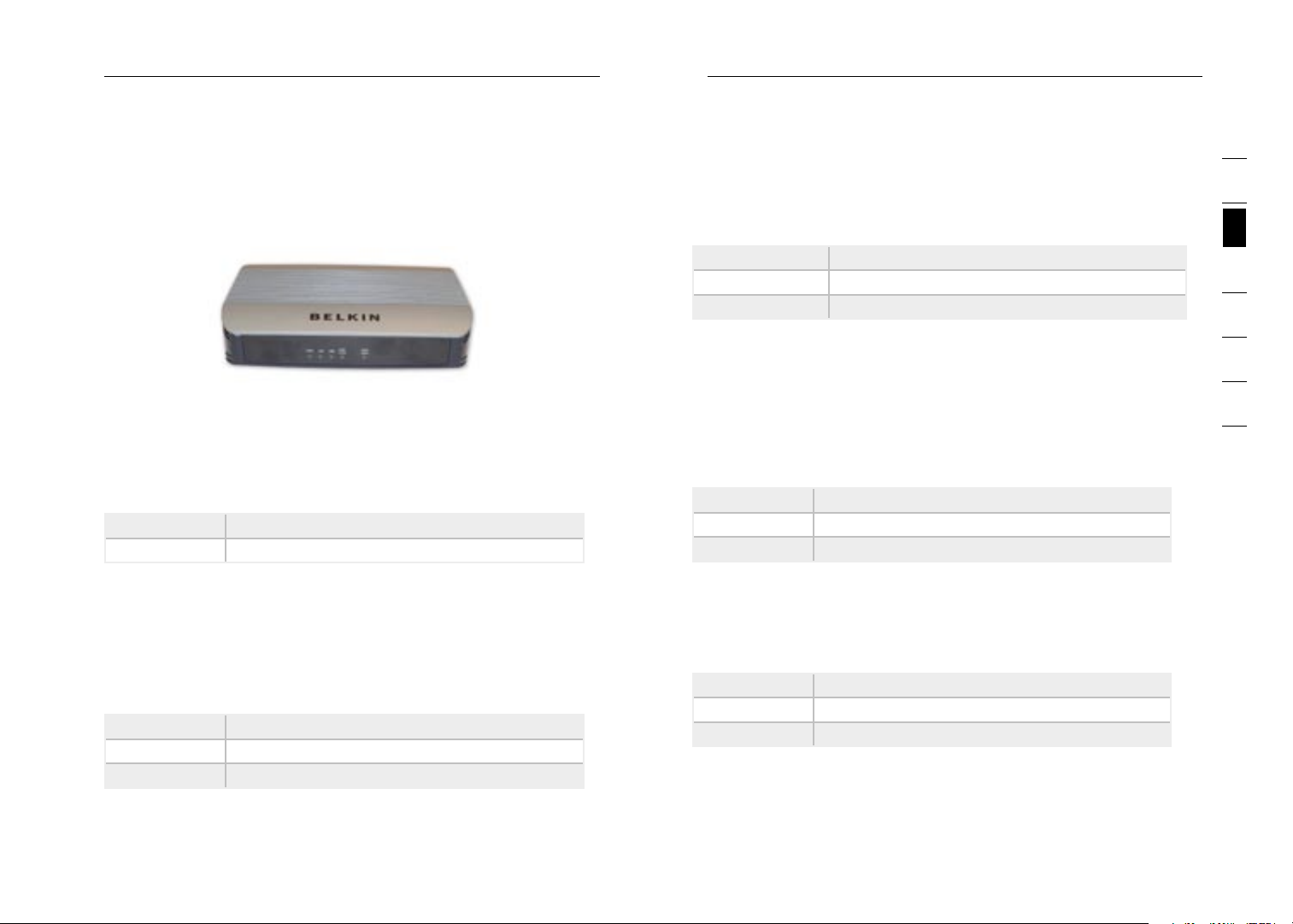
The Modem is de signed to be pla ced on a desktop. All of the cables
exit from the rear of the Modem for be tte r organ iza tion and utility. The
LED indicato rs are easily vi sible on the front of the Modem to provide
you with inf orm ation about netw ork activity and statu s.
Front Panel
1. Power LED
When you app ly power to the Mod em or restart it , a short period
of time elap ses while the Modem bo ots up. When the Mo dem has
completely b oot ed up, the Power LE D becomes a SOLID l igh t,
indicating t he Modem is read y for use.
Off Modem is off
On Modem is on
2. LAN Statu s L ED
When a compu ter is proper ly connected to the LA N p ort on the re ar
of the Modem , t he associated LE D w ill light. A solid lig ht means a
computer or a network-enable d d evice is connect ed. When informatio n
is being sen t o ver the port, th e L ED blinks rapidly.
Off Your com put er is not connected
On - blinkin g Connected an d t ransmitting or receiving data
On Your computer is connec ted
When a compu ter is proper ly connected to the US B p ort on the re ar
of the Modem , t he LED will ligh t. Solid GREEN means a co mputer is
connected an d t he drivers are installed. When i nfo rmation is being se nt
over the por t, the LED blinks r api dly.
Off Your com put er is not connected
Gre en - blinking Connected an d t ransmitting or receiving data
Gre en Your com put er is connected
4. ADSL DATA LE D
The ADSL Dat a L ED shows you whe n t he Modem is connect ed to
the Internet. When th e LED is OFF, the M ode m is NOT connected to
the Internet. When th e LED is solid ligh t, the Modem is con nec ted to
the Internet. When th e LED is blinking, the Modem is transm itt ing or
rec eiv ing data from th e Internet.
Off Not connecte d t o Internet
On - blinkin g Connected an d t ransmitting or receiving data
On Conne cte d to Internet
5. ADSL SYN C L ED
The ADSL LED fl ashes light duri ng negotiation with yo ur ISP. It st ays
light when t he Modem is connect ed properly to y our ADSL service.
Off No ADSL conn ect ion
On - blinkin g Negotiating con nection
On ADSL lin k is up and connect ed
Back Panel
3. USB DATA L ED
Page 5

Knowing your Modem Connecting your Modem
6. ADSL
This port is fo r connection to you r ADSL line. Connec t y our ADSL line
to this port .
7. Ethernet
The Ethernet port is RJ45, 10/100 auto-n ego tiation. Connect yo ur
network-enab led computers or an y n etworking devices t o t his port.
8. USB
Thi s po rt is for connecting your Modem to the computer via USB. I f yo u
do not have Ethernet or wish to us e US B, c onnect your computer here.
9. Reset
The “Reset” button is used in rare cases when the Modem may function
improperly. Resetting the Modem will restore the Modem’s normal
operation while maintaining the programmed settings. You can also restore
the factory default settings by using the Reset button. Use the restore
option in instances where you may have forgotten your custom password.
a. Resettin g t he Modem
Push and hol d t he Reset button for one second then release it.
When the PWR li ght becomes soli d a gain the rese t i s complete.
b. Restorin g t he Factory Defau lts
Push and hol d t he Reset button for ten seconds then release it.
When the PWR li ght becomes soli d a gain the rest ore is comple te.
Connecti ng yo ur Co mputer v ia Et hernet
1. P owe r off your computer and Mo dem
2. Connec t your computer t o the Ethernet po rt on the rear of the
Modem by using an Etherne t netw ork ing cable (an Ethern et
network cable is suppli ed) .
3. P owe r on your c omputer a nd Modem.
Connecti ng yo ur Co mputer v ia US B (Wi ndows ME o r later)
1. L oca te a USB ca ble.
2. Connec t one end to your P C’s USB Po rt
3. Connec t the other en d into the por t labelle d USB on the Modem
4. Power on your computer and M odem.
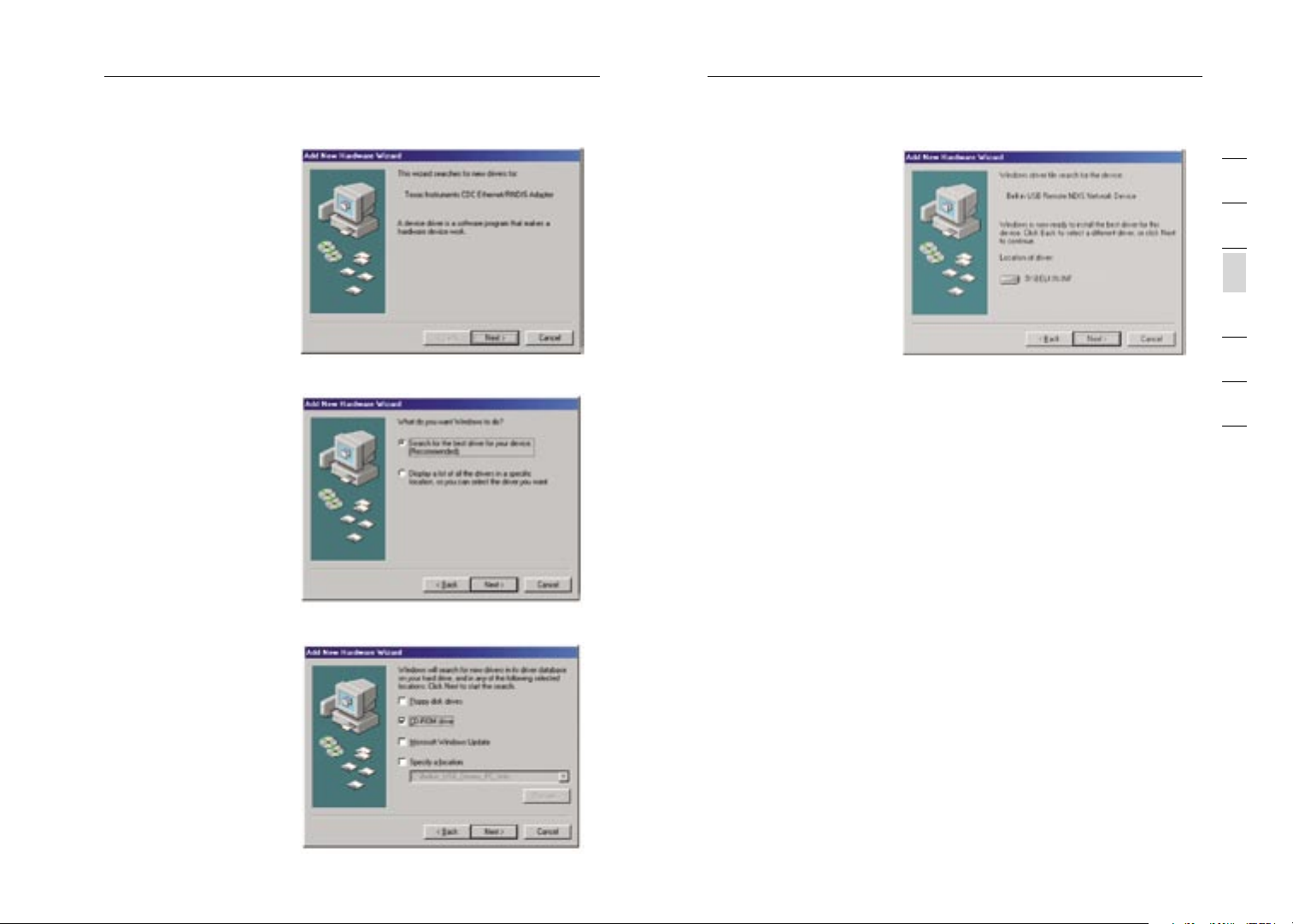
5. Windows will d ete ct new hardw are, i nsert the supplied CD i nto
the com puter the n click “Next”
6. Once the insta lle r has finished, click f inish.
Connecti ng yo ur Co mputer v ia US B (Wi ndows 98SE)
1. Locate a US B cable.
2. Connec t one end to your P C’s USB Po rt
3. Connec t the other en d into the por t labelle d USB on the Modem
4. Power on yo ur comput er and Modem.
5. Window s will detect new hardware, insert the suppl ied CD into
the c omputer t hen click “Next”.
1
2
3
sec tion
4
5
6
7
10. Power P lug
Connect the inc luded 12V 1A DC pow er supply to this i nle t. Using the
wro ng type of power adapt er may cause damage to yo ur Modem.
76
7
Page 6
98
Connecting your Modem
Connecting your Modem
9
sec tion
2
1
3
4
5
6
7
6. Select “Search
for t he best driver
for y our devic e.
(Recommended ).” and
click “Next”
7. Place a tic k next to
“CD-ROM drive” an d
click “Next”
8. Click “Next” on the
following scree n
9. Once the ins taller ha s
finished, click f inish.
Connecti ng yo ur AD SL Line
Connection f or the Modem to the AD SL line varies by c oun try and
reg ion . Typically it inv olv es line filter o r a line filter with b uil t-in splitter
to allow sim ult aneous use of AD SL service and telepho ne service on
the same tel eph one line. Please read the follow ing steps carefu lly and
select appropriate method .
1. If your tel ephone se rvi ce and ADSL service are on the same
telephone line, A DSL li ne filters are needed for eac h telephone
and d evice, su ch as answering machine, f ax machin e, and caller
ID di splay. Additional splitters may be used to se par ate telep hon e
lines for tele pho ne and the Modem.
Note: Do not connect the ADSL line filter b etween th e wall jack
and t he Modem— thi s will preve nt ADSL service from reaching the
Modem.
2. If your tel ephone se rvi ce and ADSL service are on the same
Page 7

Connecting your Modem Setting up your Computer
telephone line an d you are using a n ADSL line filter w ith built -in
splitter, connect t he splitt er to the tele pho ne wall jack p roviding
ADSL service. The n, con nec t the telephone cord from the AD SL
line filter RJ 11 port generally labelled “ADSL” t o the RJ11 por t
labelled “ADSL” o n the back of your Modem. Connect telephony
device to the other port on the ADSL sp lit ter co mmo nly label led
“Phone”. An ad dit ional ADS L line filter is needed for another
telephone and dev ice on the same line .
Note: One RJ11 telephone cord is su pplied. W hen insertin g an
RJ11 plug, be sure the tab o n the plug cli cks into position to
ensure that it is prope rly seate d.
3. If you h ave a dedicated A DSL se rvi ce teleph one line with an RJ11
wall jack, sim ply conne ct a telephone co rd from t he wal l jack to
the R J11 port labelled “ADSL” on the back of you r Modem.
In ord er for your compute r t o properly co mmunicate with your Mo dem,
you will nee d t o change your co mpu ter’s “TCP/ IP Ethern et” settings to
“Obtain an I P a ddress aut oma tically/Using DHCP” . T his is normally the
default sett ing in most home co mpu ters.
Manually Conf iguring Network Adapters in Windows XP,
2000, or NT
1. Click “Start”, “Settings”, and t hen “Cont rol Pa nel ”.
2. Double -cl ick on the “Ne twork and dial-up connections” icon
(Windows 2000) or the “Network Connections” icon (Wi ndows
XP).
3. Right- cli ck on
the “ Local Area
Connection”
associated with y our
network adapter a nd
select “Propert ies ”
fro m the drop-down
menu.
4. In the “ Loc al
Are a Connection
Pro per ties” win dow,
click “Internet
Pro toc ol (TCP/
IP)” and click the
“Prope rties” bu tto n.
5. If not a lready
selected, select “Obtain a n IP address automatical ly” and “Obtain
DNS s erver add ress a utomatically”. Click “OK”.
1
2
3
4
sec tion
5
6
7
1110
11
Page 8
1312
Setting up your Computer
Setting up your Computer
13
sec tion
2
1
3
4
5
6
7
Your net wor k adapter(s) are now configured for use with the Mo dem.
Manually Conf iguring Network Adapters in
Windows 98SE or Me
1. Right- cli ck on
“My N etwork
Neighbourhoo d” and
select “Propert ies ”
fro m the drop-down
menu.
2. Select “TCP/IP ->
settings” for you r
installed network
adapter.
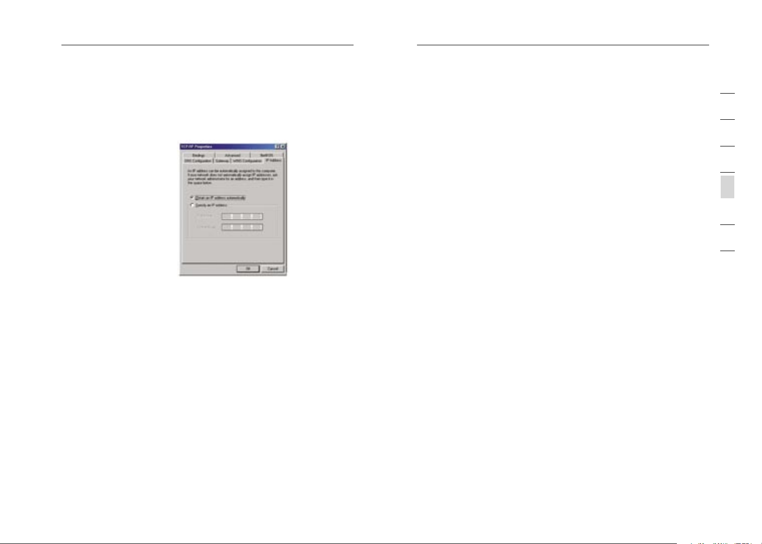
3. If not a lready
selected, select
“Obtain an IP addres s
automaticall y” on the
IP ad dress tab.
4. Click the “ Gateway” tab . Highlig ht anythi ng listed under “ Installed
Gateways”, and cl ick “R emo ve”
5. Click the “ DNS Confi gur ation” ta b. Click “Disable DNS”
6. Click “OK”.
Restart the com puter. When the compu ter restarts, yo ur network adapter( s) are
now configured for use wi th the Modem.
Manually Conf iguring Network Adapters in Mac OS up to 9.x
In ord er for your compute r t o properly co mmunicate with your Mo dem, you will
need to chan ge your Mac compute r’s TCP/IP set tin gs to DHCP.
1. Pull down t he Apple menu. Select “ Control Panels” an d sele ct “TCP/IP”.
2. You will s ee the TCP/IP control panel. Select “E therne t Built-I n” or
“Ethernet” in the “Connect via:” d rop-down menu.
3. Next to “Co nfigure”, if no t alre ady se t, choose “Using DHCP S erv er” . This
will tell the computer to ob tain an IP add ress from the M ode m.
Manually Conf iguring Network Adapters in Mac OS X
1. Click on th e “System Prefe rences” icon.
2. Select “Network” from the “System P referen ces ” menu .
3. Select “Built-in Ethernet” ne xt to “Show” i n the Network menu.
4. Select the “TCP/IP” tab . next to “ Configure”, you sh ould s ee “Manually ”
or “U sing DHCP ”. If you d o not, check t he PPPoE tab t o make sure that
“Connect using PP PoE” i s NOT selected.
5. If not a lready se lected, s elect “Us ing DHCP” next to “Conf igu re”, t hen cl ick
“Apply Now”.
Page 9
1514
Setting up your Computer
Setting up your Computer
15
sec tion
2
1
3
4
5
6
7
Your network adapter(s) a re now confi gured for use with t he Mod em.
Recommen ded Web Browse r Set tings
In most case s, you will not nee d t o make any changes to your web
bro wse r’s setting s. If you are ha ving troub le accessing the Inter net or th e
advanced web -ba sed user interfa ce, then change your b rowser’s settings
to the recommended settin gs in this section.
Internet Explorer 4.0 or Higher
1. Start your web browser. Sele ct “Tool s” then “Inter net Op tio ns” .
2. In the “ Int ern et Options” screen , there are three sel ect ions:
“Never di al a connection”, “Dial whenever a networ k connection is
not p resent”, and “A lways dia l my default c onnection”. If you can
make a selecti on, selec t “Never dial a connection ”. If you c ann ot
make a selecti on, go
to th e next step.
3. Under the “ Intern et
Options” screen , click
on “C onnections”
and s elect “LA N
Settings...” .
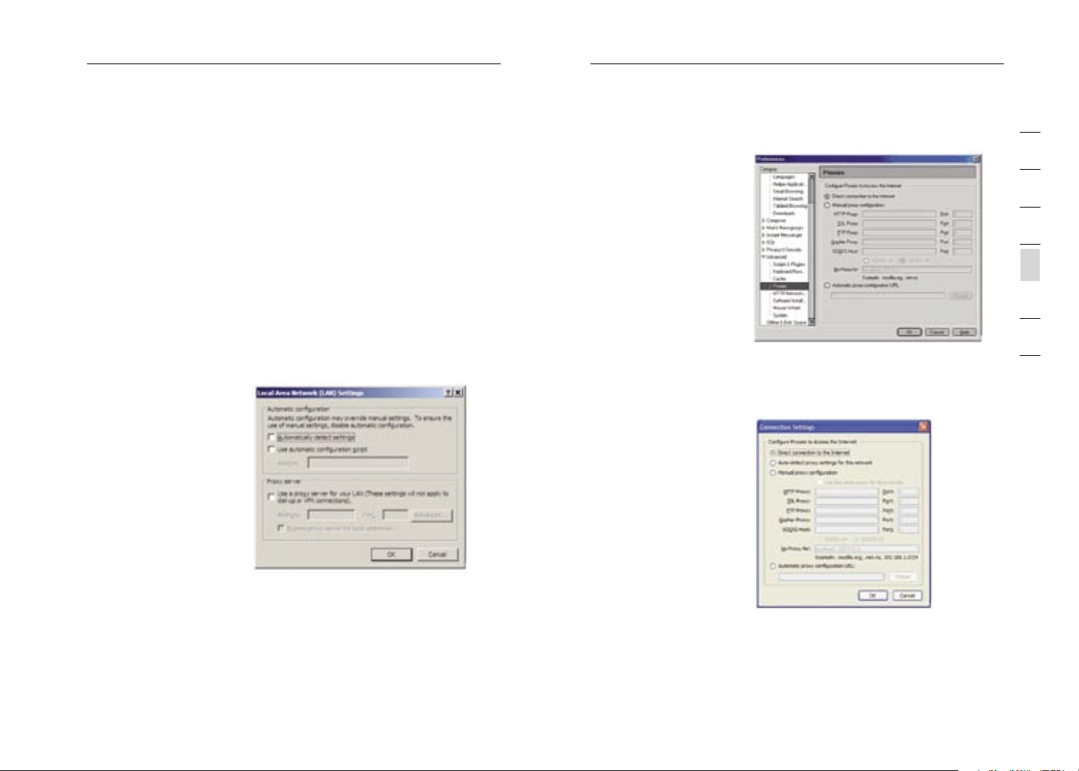
4. Make sure there
are no c heck mark s
next to any of t he
displayed options:
“Automatical ly
detect settings”,
“Use automatic
configuratio n script” ,
and “ Use a proxy
server”. Click “O K”. Then c lick “OK” again in t he “Internet O ptions”
page.
Netscape Nav iga tor 4.0
or Higher
1. Start Netscape,
click on “Edit ” then
“Prefe rences”.
2. In the “ Prefere nce s”
window, click o n
“Advanced” then
select “Proxies ”. In
the “ Proxies” window,
select “Direct
connection to the Inter net”.
Mozilla FireFox 1.0 or
Higher
1. Start FireFo x, click
on “Tools” th en
“Options”
2. In the “ Gen eral” tab ,
click “Connection
Settings”
3. Select “Dire ct
Page 10

Setting up your Computer Manually Configuring your Modem
connection to the Inter net” and th en click OK.
MAC OS – Saf ari
1. Start Safari
2. Click “Prefe rences”.
3. Click the “ Advanced” ta b.
4. Click “Change Settings”. The Net wor k pane l will open to the
Pro xie s tab.
5. Verify all b oxes a re unc hec ked. To rem ove a checkmark, click in
the b ox once.
6. Click the “ Apply Now ” button.
7. Close “System Preferences“
8. Close the “ Prefere nces”.
Understa nding the Web-Based User Interface
The Modem ca n b e configured by any bro wse r such as Internet
Explorer 4.0 or above. Us ing the web management in terface, you may
configure the Modem and v iew statistics to moni tor network activit y.
Type “10 .1. 1.1” (do not type i n a nything else such a s “ http://” or
“www”) in yo ur browser’s addre ss bar. Then press th e “Enter” key.
The followin g s creen will
appear in yo ur browser
to pro mpt you to log in.
The default Pas sword
is “admin”. Ent er the
Password, and then click
the “Log In” bu tton to log
in.
Navigati ng th e Web Browser Inter face
The Modem’s management int erface consists of a S etup Wizard a nd
an Advanced Set up section.
Setup Wizard
Use the Setu p W izard to q uic kly configure the Modem with you r
username and passw ord.
1
2
3
4
5
sec tion
6
7
Advanced Set up
Advanced Set up offers more advanced fu nct ions such as hacker
attack detec tio n, IP and MAC ad dress filtering, vi rtual server set up,
virtual DMZ hos t, and many more functions.
1716
17
Page 11

1918
Manually Configuring your Modem
Manually Configuring your Modem
19
sec tion
2
1
3
4
5
6
7
Making Confi gur ation Changes
Configurable pa rameters have a dia log box or a dro p-down list. Onc e
a configurat ion change has been ma de on a page, most tim es you will
need to clic k t he “SAVE SETTINGS” o r “ NEXT” button at the bo ttom
of the page to enable the new s ett ing. Some options m ay also have an
“ADD” button al so.
Note: To e nsure proper scre en refresh after a command en try, be sure
that Internet Expl orer 5.0 and abo ve is configured as follows: Und er
the menu Tools/Internet Options /Ge neral/Temp ora ry Intern et Files/
Settings, th e s etting for “Chec k f or newer versions o f s tored page s”
should be “E ver y visit to the p age .”
Setup Wizard
After succes sfu lly logging into th e Modem, you will b e p rompted wi th
the followin g s creen. You can quickly sele ct your country, add in your
username and passw ord for your ISP into the Modem. O nce you have
added all de tai ls correct ly, click “ Sav e S ettings”.
The status s ect ion shows:
• Line Status – detects if the telephone line has correct line sync
• Line Mode – This shows the current line mode, (G.DMT is common for
ADSL and ADSL2/ADSL2+)
• Connected/NO Connection – Shows current Internet connection status
• WAN IP – This is the IP Address that the ISP has assigned to the
Modem.
Advanced Set up
Clicking the Ho me icon
ret urns you to the home
page. The Ma in Menu links
are us ed to navigate to
other menus tha t display
configuratio n p arameters
and statisti cs.
The Modem’s advanced
management i nte rface
contains 14 mai n menu
items as des cri bed in the
following ta ble .
Page 12

2120
Manually Configuring your Modem
Manually Configuring your Modem
21
sec tion
2
1
3
4
5
6
7
Menu Descrip tio n
Menu Description
System Sets the loc al time zone, the p ass word for
administrato r a ccess, the IP ad dress of a PC th at
will be allo wed to manage the M ode m remotely,
and the IP a ddress of a D oma in Name Server.
WAN Specifies th e I nterne t connection settin gs.
LAN Sets the TCP /IP configuration f or the Modem LAN
interface an d D HCP clients.
NAT Shares a single ISP accou nt with multiple users ,
sets up Port fo rwarding.
Route Sets routing parameters a nd displays the current
rou tin g table.
Firewa ll Configures a variety of se cur ity and speciali zed
functions in clu ding: Access Con trol, URL blocki ng,
Internet access co ntrol schedul ing , Intruder
detection, a nd DMZ.
ADSL Sets the ADSL opera tio n type and shows th e
ADSL status.
UPnP Configures the Modem’s Universal Plug an d Play
features.
DDNS Configures the Dynamic DN S f unction.
Tools C ont ains options to bac k up and rest ore the
curren t configuration, restore a ll configuration
settings to the factory default s, update system
firmware, or reset the system.
Status Pro vid es WAN con nec tion type and st atu s,
firmware and hardwa re version nu mbe rs, system
IP settings, as well as DHCP, NAT, and firewall
information.
System Settin gs
Time Setting s
Set the t ime zone and tim e
server for t he Modem.
This informa tio n is used
for log entr ies and client
access control.
Check “Enabl e A utomatic
Time Server Mai ntenance”
to automatic all y maintain
the Modem’s system time
by synchronizing with a
public time ser ver over the
Internet. Then con fig ure
two different time ser vers by selectin g t he options in the P rim ary
Server and S eco ndary Server fie lds .
Password Settings
Use this pag e t o restrict
access based on a
password. By default, the
password is “admin”.
Passwords can contain
fro m 3 to12 alphanumeric
characters w hic h are case
sensitive.
Note: If you r p assword
is lost, or you cannot
gain access to the user
interface, p ress the reset
button on th e rear panel
(holding it dow n for at
least 10 sec ond s) to rest ore the facto ry defaults. (By defau lt the
password is “admin” passw ord.)
Enter a maxi mum Idle Time Out ( in minutes) to define a m aximum
period of ti me an inactive logi n s ession will be main tai ned. If the
connection i s i nactive for long er than the maximum id le time, it will be
logged out, and you will have t o l ogin to the web man age ment system
again. (Defa ult : 10 minutes)
Page 13

2322
Manually Configuring your Modem
Manually Configuring your Modem
23
sec tion
2
1
3
4
5
6
7
Remote Manag eme nt
By default, man agement
access is on ly available
to users on you r local
network. However, y ou can
also manage the Modem
fro m a remote host by
checking the En abled
check box, a nd if you
wish you can se t a HOST
ADDRESS, whi ch will only
allow that c omp uter to use
rem ote management. The
port field s hou ld be left as
the default set ting of 8080
unless you n eed to change it. A fte r any changes are made you must
click on “Sa ve Settings” to app ly them.
Note: If you ch eck “Enabled” an d s pecify an IP address of 0.0.0.0, an y
host can man age the Modem.
For re mote management via WAN IP ad dress you need t o c onnect
using port 8 080 . Simply enter WAN IP address followed by :8080 in the
addres s field of your web browser, for example, 123. 123 .123.123:8080.
This applies un less you change the port setting, in w hic h case you
need to subs tit ute the 8080 for wh atever port you ass ign .
DNS
Domain Name Ser vers are
used to map a d omain
name (e.g., www.somesite.
com) to the equ ivalent
numerical IP ad dress
(e.g., 64.14 7.2 5.20). Your
ISP should p rovide the IP
addres s of one or more
Domain Name Ser vers.
If your ISP require s y ou
to manually spe cify the
addres ses, enter them on
this page.
WA N
Specify the WAN (Wide Area Network) co nnection paramet ers provided
by your Inte rnet S erv ice Provid er (ISP).
ATM PVC
The Modem us es
ATM (Asynchronous
Transfer Mode) as it s
WAN in terface. Click o n
each ATM VC for WAN
configuratio n.
See the tabl e b elow
for a descri pti on of the
parameters.
Parameter Description
Description Click on the VC to set the valu es for the
connection.
VPI/VCI Vir tua l Path Identifier ( VPI ) and Virt ual Circuit
Identifier ( VCI ).
Encapsulatio n Specifies ho w t o handle multipl e p rotocols at t he
ATM transport lay er.
• VC-MUX - Point-to-Point Protocol over ATM Virtual
Circuit Multiplexer (null encapsulation) allows only
one protocol running per virtual circuit with less
overhead.
• LLC - Point-to-Point Protocol over ATM Logical
Link Control (LLC) allows multiple protocols
running over one virtual circuit (using slightly more
overhead).
Pro toc ol Pro toc ol used for the con nec tion
Page 14

2524
Manually Configuring your Modem
Manually Configuring your Modem
25
sec tion
2
1
3
4
5
6
7
ATM Int erface
Clicking on the ATM VC
brings up th e f ollowing
screen . The Modem
uses ATM as its WAN
interface. P rotocols
including 14 83 Routing,
1483 Bridgin g, MAC
Encapsulated Ro uting
(MER), PPPoA an d PPPoE
with LLC-SNA P a nd VCMux encapsul ati ons are
supported fo r e ach ATM
PVC.
When you hav e f inished
entering you r c onnection parame ter s, click “SAVE SETINGS” . You
can verify t hat you have establ ish ed an ADSL connecti on by clicking
Status at th e b ottom of the lef t-h and menu.
See the tabl e f or a description of the parameters.
Parameter Description
Pro toc ol • Disable: Disables the connection.
• 1483 Bridging: Bridging is a standardized layer
2 technology. It is typically used in corporate
networks to extend the physical reach of a single
LAN segment and increase the number of stations
on a LAN without compromising performance.
Bridged data is encapsulated using the RFC1483
protocol to enable data transport.
• PPPoA: Point-to-Point Protocol over ATM is a
method of encapsulating data for transmission to
a far point.
• 1483 Routing: 1483 Routing allows a simple, lowcost connection to the Internet via a standard
Ethernet port. The Modem looks up the network
address for each packet seen on the LAN port. If
the address is listed in the routing table as local, it
is filtered. If the address is listed under the ADSL
port, it is forwarded. Or if the address is not found,
then it is automatically forwarded to the default
Modem (i.e., the Modem at the head end).
• PPPoE: Point-to-Point over Ethernet is a common
connection method used for xDSL.
• MAC Encapsulated Routing: If your ADSL service
is a Bridged mode service and you want to share
the connection to multiple PC’s, please select
MAC Encapsulated Routing. MER is a protocol
that allows you do IP routing with NAT enabled.
VPI/VCI See Vi rtual Path Identifi er (VPI) and Vir tual Circuit
Identifier ( VCI ). Data flows are broke n u p into fixed
length cells , e ach of which con tai ns a Virtual Pat h
Identifier ( VPI ) that identifie s t he path between two
nodes, and a Virtual Circuit Identifie r ( VCI) that
identifies t he data channel wit hin that virtual path.
Each virtual ci rcuit main tai ns a constant flow of
cells betwee n t he two end point s. When there is
no data to t ran smit, empty cell s a re sent. When
data needs t o b e transmitted, i t i s immediately
inserted int o t he cell flows.
Page 15

2726
Manually Configuring your Modem
Manually Configuring your Modem
27
sec tion
2
1
3
4
5
6
7
Encapsulatio n Shows the pa cke t encapsulation typ e.
Packet encap sul ation specifies how to handle
multiple protocols at the ATM tra nsport layer.
• VC-MUX: Point-to-Point Protocol over ATM Virtual
Circuit Multiplexer (null encapsulation) allows only
one protocol running per virtual circuit with less
overhead.
• LLC: Point-to-Point Protocol over ATM Logical
Link Control allows multiple protocols running over
one virtual circuit (using slightly more overhead).
QoS Class ATM QoS classes i ncl uding CBR, UBR a nd VBR .
PCR/SCR/MBS QoS Paramete rs - PCR (Peak Cell Ra te), SCR
(Sustainable Ce ll Rate) and MBS (M aximum Burst
Size) are configurable.
IP Address If your I P a ddress is assigned by the ISP each time
you connect, le ave this field a ll zeros. Otherw ise ,
enter your I SP supplied static IP address here.
Subnet Mask If your subnet mask is as signed by the IS P
each time yo u c onnect, leave th is field all zeros.
Otherwise, e nte r your subnet ma sk here.
Connect Ty pe Sets connect ion mode to always con nected,
automatic or ma nual connection.
Idle Time En ter the maximum idl e t ime for the
Internet connectio n. (minutes) After thi s t ime has
been exceede d t he connection wi ll be terminated.
Username Enter user n ame .
Password Enter passwo rd
Confirm
password
MTU Lea ve the Maximum Tran smi ssion Unit (MTU)
Confirm Pass word
at the defau lt value (1500) unl ess you have a
particular reason to chan ge it.
Clone MAC Ad dress
Clicking on the Clone
MAC Address brings up
the followin g s creen.
Some ISPs ma y require
that you register your
MAC address with them. If
this is the cas e, the MAC
addres s of the Modem
must be chan ged manually
to the MAC a ddress that
you have registered wi th
your ISP. Most I SP’s in
Australia an d N ew Zealand
do not require this op tion.
LAN
Use the LAN (Lo cal
Are a N etwork) menu to
configure the LAN IP
addres s and to enable the
DHCP server for dynamic
client address allocation .
Page 16

2928
Manually Configuring your Modem
Manually Configuring your Modem
29
sec tion
2
1
3
4
5
6
7
Parameter Description
IP Address The IP address of the Mod em.
IP Subnet Ma sk The subnet m ask of the Modem.
DHCP Server To dy namically assign an IP addres s t o client PCs,
enable the D HCP (Dynamic Host C onf iguration
Pro toc ol) Server.
Lease Time Set the DHCP Lea se Time
DHCP Option
60 Vendor ID
Lease Time Specify the leng th of time that the DH CP will
Start IP Sp ecify the start IP address of th e D HCP pool.
End IP Spec ify the end IP address of the DH CP poo l.
Domain Name If your ne two rk uses a domain na me, enter it here.
If you wish you can Specify the Na me of your
DHCP Server (Op tional)
assign an IP ad dress to a co mputer for.
Do not inclu de the gateway address of the
Modem in the cl ient addre ss pool. (See “TCP/IP
Configuratio n”) . If you attempt to include the
Modem gatewa y a ddress (10 .1. 1.1 by default) in
the DHCP poo l, an error d ial og box will appear.
If you chang e t he pool range, m ake sure the fir st
three octets match the ga tew ay’s IP add ress, i.e.,
10.1.1.xxx.
Otherwise, l eav e this field bla nk.
DHCP Client Lis t
The DHCP Cli ent s List
displays the IP Address,
Host Name an d M AC
Addres s of each client
that has requested an IP
addres s since the last
reb oot of the Modem.
Check the FI X b ox to have
the IP address and the
MAC address linked so
that the IP add ress will
always be as sig ned as it is
on this screen.
NAT
Fro m t his section you can co nfigure th e Virtual Server, and Sp ecial
Application fea tures that provide cont rol over the TCP / U DP port
openings in the Modem’s fi rewall. Th is sec tion can be used to support
several Inte rnet b ase d applications such as web, email, FTP, and
Telnet.
NAT Set tings
NAT allows one or mo re
public IP ad dresses to be
shared by multiple internal
users. Yo u c an enable
or disable N AT he re.
Recommended set ting =
Enable.
Page 17

3130
Manually Configuring your Modem
Manually Configuring your Modem
31
sec tion
2
1
3
4
5
6
7
Addres s M apping
Use Address Mapping to
allow a limi ted number of
public IP ad dresses to be
translated i nto multiple
private IP a ddresses for
use on the i nte rna l L AN
network. Thi s a lso hides
the internal netwo rk for
increa sed privacy and
security.
Port Forwarding
If you confi gure the Port
Forwarding settings,
rem ote users accessing
services suc h a s web
or FTP at yo ur local site
via public I P a ddresses
can be autom ati cally
red irected to local se rvers
configured with private
IP addresses. In other
words, depending on
the re quested service
(TCP/UDP por t n umber),
the Modem redirects th e
external service request to the ap propriate ser ver (located at ano the r
internal IP address).
For example, if you set Type /Public Port to TCP /80 (HTTP or web)
and the LAN IP Address/LA N P ort to 10.1.1.3/80, th en all HTTP
req ues ts from outsi de users will be tr ans ferred to 10. 1.1 .3 on port 80.
Theref ore, by just ent ering the IP add ress provi ded by the ISP, Inter net
users can ac ces s the service th ey need at the local a ddress to whi ch
you re direct them.
The more common TCP servi ce ports include:
HTTP: 80, FT P: 21, Telnet: 23, an d POP3: 110.
Special Appl ica tions
Some applica tio ns, such
as Internet gaming ,
video conferencing,
Internet telephony an d
others, require mul tip le
connections. Th ese
applications ca nnot work
with Network Ad dress
Translation (NAT) enab led .
If you need to run
applications th at require
multiple con nec tions,
use the foll owi ng screen
to specify t he additional
public ports to be opened for e ach application.
Specify the pub lic port number nor mally associated wi th an
application in the Trigger Port fiel d. Set the proto col type to TCP
or UDP, and then enter the por ts that the appl ica tion requires. The
ports may be in the format 7, 1 1, 57, or in a range, e.g ., 72-96, or a
combination of both, e.g., 7, 1 1, 57, 72-96.
Popular appl ica tions
req uir ing multiple ports
are li sted in the Popular
Applications fi eld. From
the drop-down li st, choose
the applicat ion and then
choose a row number to
copy this da ta into.
Note: Choosi ng a row
that already contains dat a
will overwri te the curren t
settings.
Page 18

3332
Manually Configuring your Modem
Manually Configuring your Modem
33
sec tion
2
1
3
4
5
6
7
NAT Map ping Table
NAT Mapping Tabl e
displays the cu rrent
NAPT (Networ k A ddress
Port Transla tio n) address
mappings. Th e N AT
addres s mappings are
listed 20 li nes per page,
click the co ntrol buttons
to move forw ards and
backwards. As the NAT
mapping is d yna mic, a
Refres h button is prov ided
to ref resh the NAT
Mapping Ta ble with the
most up-to-d ate values.
The content of the NAT Mapping Tabl e i s described as foll ows :
• Protocol - protocol of the flow.
• Local IP - local (LAN) host’s IP address for the flow.
• Local Port - local (LAN) host’s port number for the flow.
• Pseudo IP - translated IP address for the flow.
• Pseudo Port - translated port number for the flow.
• Peer IP - remote (WAN) host’s IP address for the flow.
• Peer Port - remote (WAN) host’s port number for the flow.
Route
These pages def ine routin g related par ame ters, including sta tic routes
and Routing Inf ormation Prot ocol (RIP) paramete rs.
Static Route Pa rameters
Static routing is the man ual method used to set up routing. A n etwork
administrato r e nters rout es into the Modem usin g t he following
screen s. This method has the advantage of being predictable, an d
simple to se t u p. It is easy to ma nage in small netwo rks but does not
scale well.
Parameter Description
Index Displays the n umb er of the rou te.
Network
Addres s
Subnet Mask Dis plays the subnet ma sk of the rem ote network
Gateway Displays the WAN IP ad dress of the gat ewa y to
Configure A llows you to modify or delete configur ati on
Displays the IP address o f t he remote com puter
for which to se t a static ro ute.
for which to se t a static ro ute.
the re mote network.
settings
Page 19

3534
Manually Configuring your Modem
Manually Configuring your Modem
35
sec tion
2
1
3
4
5
6
7
Click Add or Ed it to display th e f ollowing page and a dd a new static
rou te to the list.
Parameter Description
Index Displays the n umb er of the rou te.
Network
Addres s
Subnet Mask Ent er the subnet mask of the remote ne twork for
Gateway Enter the WAN IP address of the gat ewa y t o the
Enter the IP ad dress of t he remote com put er for
which to set a static rou te.
which to set a static rou te.
rem ote network.
RIP Paramete r
The device s upp orts Routing Inf orm ation Protoco l ( RIP) v1 and v2 t o
dynamically exc hange rout ing information with a dja cent Modems.
Parameter Description
RIP mode Globally enables o r d isables RIP.
Auto summary If Auto summary is dis abl ed, then RIP pac ket s will
include sub- net work information from all sub¬ne t
works connec ted to the ADSL Mod em. If enabled,
this sub-net wor k information wi ll be summarized
to one piece of information cov eri ng all subnetworks.
Interface The WA N interface to b e c onfigured.
Operation
Mode
Version Se ts the RIP versi on to use on this inte rfa ce.
Poison Rever se A method for preventing l oop s that would cause
Disable: RIP di sabled on this i nte rface.
Enable: RIP ena bled on this int erf ace.
Silent: List ens for route broadcasts a nd updates
its ro ute table. It does not participate in sen din g
rou te broadcasts.
endless retransmission of da ta traffic .
Page 20

3736
Manually Configuring your Modem
Manually Configuring your Modem
37
sec tion
2
1
3
4
5
6
7
Authenticati on
Required
Authenticati on
Code
RIP sends routing-update mes sages at regu lar intervals and w hen
the network top ology changes. W hen a Modem rece ive s a routin g
update that inc ludes changes to an entry, it upd ates its rout ing table
to ref lect the new rou te. RIP Modems m ain tain only the best route to
a destinatio n. After updating i ts routing table , t he Modem immedia tel y
begins trans mit ting routi ng updates to inform o the r network Modems
of the chang e.
None: No aut hen tication.
Password: A password a uthentication ke y i s
included in the packet. If this do es not match
what is expe cte d, the packet wi ll be discarded.
This method provides very li ttle security as it
is possible to learn the authentication key by
watching RIP pa ckets.
MD5: An algo rit hm that is used to verify data
integrity th rough the creation of a 12 8-b itmessage
digest from data input (w hic h may be a message
of any lengt h) that is claimed to be as unique to
that specifi c d ata as a fingerp rin t is to a specific
individual.
Password or MD5 Authentic ati on key.
Routing Ta ble
Parameter Description
Flags Indicates th e route statu s:
C = Direct connection on the same subnet.
S = Static M ode m
R = RIP (Rou tin g Information Protocol) assigned
rou te.
I = ICMP (In ter net Co ntrol Mess age Protocol)
Redire ct route.
Network
Addres s
Netmask T he subnetwork associat ed with the destinatio n.
Gateway The IP address of the Mod em at the next hop to
Interface The local in ter face throu gh which the next hop of
Metric When a Modem receives a routing update t hat
Destination IP address
This is a te mpl ate that identif ies the address bit s
in the desti nat ion addres s u sed for ro uti ng to
specific sub net s. Each bit that co rresponds to a
“1” is part of the subnet mask num ber; each bit
that corresponds to “0” i s p art of the host num ber.
which frames are forwarded.
this route is reach ed.
contains a n ew or changed desti nat ion network
entry, the Modem adds 1 to the metric value
indicated in th e update and ent ers the network in
the ro uting table.
Page 21

3938
Manually Configuring your Modem
Manually Configuring your Modem
39
sec tion
2
1
3
4
5
6
7
Firewa ll
The Modem’s firew all
enables acce ss control
of client PC s, blocks
common hacke r a ttacks,
including IP Sp oofing,
Land Attack, Pi ng of
Death, IP wi th zero lengt h,
Smurf Attack , U DP port
loopback, Sn ork Attack,
TCP null sca n, and TCP
SYN flooding .
Access Control
Access Control allows use rs to define the outgo ing traffic p erm itted or
not-permitte d t hrough the WAN inter fac e.
The Modem ca n a lso limit the ac ces s of hosts within t he local area
network (LAN ). The MAC Filterin g Table allows the Mo dem to enter up
to 32 MAC ad dresses that are not allow ed access to the WAN port.
The followin g i tems are d isp layed on the Access Co ntrol screen:
Parameter Description
Enable Filte rin g Enables or dis ables the filter ing function. Function
Normal Fi ltering
Table
Click Add PC on the Access Cont rol screen to view the follow ing page.
Displays the IP address ( or an IP address range)
filtering ta ble .
Access Control Add PC
The settings in the scree n
shot below w ill block
all email se ndi ng and
rec eiv ing.
Define the a ppropriate
settings for cl ient PC
services (as sh own
above). Clic k “ OK” to save
your setting s. The added
PC will now app ear in the
Access Control page.
MAC Filter
Use this pag e t o block
access to yo ur network
using MAC ad dresses.
The Modem ca n a lso limit
the access o f h osts within
the local area network
(LAN). The M AC Filtering
Table al low s the Modem
to enter up to 32 MAC
addres ses that a re allo wed
access to th e WAN port .
All other de vic es will be
denied acces s.
Page 22

4140
Manually Configuring your Modem
Manually Configuring your Modem
41
sec tion
2
1
3
4
5
6
7
URL Blocking
To confi gure the URL
Blocking fea ture, use the
table below to specify the
web sites (w ww.somesite.
com) and/or key words
you want to fil ter on your
network.
To compl ete this
configuratio n, you will
need to create or modify
an access ru le in “Access
Contro l”. To modify an
existing rul e, click the Edit
option next to the rule you
want to modi fy. To c reate a ne w r ule, click on the A dd PC option.
Fro m t he Access Contro l Page, Add PC s ect ion, check the opti on for
“WWW with UR L B locking” in the Cli ent PC Service tabl e t o filter out
the web site s a nd keyword s s elected below, on a specific PC.
The Modem al low s the user to bl ock access to web site s f rom a
particular P C b y entering eithe r a full URL addres s or just a keyw ord.
This feature can be used to protect ch ild ren fro m accessing violent or
pornographic web s ite s.
Schedule Rul e
You may fil ter Inter net
access for l oca l clients
based on rul es.
Each access con trol rule
may be activ ate d at a
scheduled ti me. Define the
schedule on the Schedule
Rule page, a nd apply the
rule on the Acc ess Contro l
page.
Click Add Sc hed ule Rule.
Edit Schedul e R ule
You can create and edit
schedule rul es on this
page.
Define the a ppropriate
settings for a schedule
rule (as sho wn on the
above screen). The rule
in the screen shot above
pro hib its emailing after
8.00am to 11 .59 pm. Upon
completion, cli ck “OK” to
save your sc hed ule rules.
Intrusion De tec tion
The Modem’s firew all
inspects pac ket s at
the applicat ion layer,
maintains TC P a nd UDP
session info rma tion
including ti meo uts and
number of ac tiv e sessions,
and provides the ability to
detect and p revent certai n
types of net wor k attacks
such as Deni al- of-Service
(DoS) attack s.
Page 23

4342
Manually Configuring your Modem
Manually Configuring your Modem
43
sec tion
2
1
3
4
5
6
7
Net work attacks that deny
acc ess to a network device
are called DoS attacks.
DoS att acks are aimed
at devi ces and networks
wit h a connection to the
Int ernet. Their goal is not
to stea l information, but
to disa ble a device or
net work so users no longer
hav e ac cess to network
resources.
The Modem protects
against DoS att acks
including: P ing of Death
(Ping flood) at tack, SYN
flood attack , I P fragment
attack (Te ardrop Att ack),
Brute-force attack, Land
Attack, IP S poo fing
attack, IP w ith zero leng th,
TCP null sca n ( Port
Scan Attack) , U DP port
loopback, Sn ork Attack.
Note: The fi rewall does n ot
significantl y a ffect syst em
performance, so we advise
enabling the prevention
features to protect yo ur
network.
Parameter Defaults Des cri pti on
Enable SPI
and AntiDoS firewall
pro tec tion
Yes The Intrusion D ete ction feature of
the VoIP M ode m limits the access
of incoming tra ffic at th e WAN port .
When the Sta tef ul Packet Inspec tio n
(SPI) feature is turned on, all in coming
packets are blocked excep t t hose
types marked wi th a check in th e
Stateful Pac ket Inspection sect ion at
the top of t he screen.
Stateful Pac ket
Inspection
Discard Ping
fro m WAN
Discard
This option all ows you to selec t
different applicati on types that are
using dynami c p ort numbers. If you
wish to use Sta teful Packet Ins pec tion
(SPI) for bl ock ing packets, cli ck on the
Yes radi o b utton in the “Enabl e S PI and
Anti-DoS firewall prot ection” field an d
then check t he inspection type tha t you
need, such a s P acket Fragmentat ion ,
TCP Connecti on, UDP Session, FT P
Service, H.3 23 Service, and TFT P
Service. It is called a “Statef ul” packet
inspection b eca use it examines the
contents of the packet to deter min e
the state of th e communication; i. e.,
it ensures that the state d d estination
computer has previously requested the
curren t communication. Th is is a way
of ensuring tha t all communicat ion s are
initiated by th e recipien t c omputer and
are ta king place only wit h s ources tha t
are kn own and trusted from previ ous
interactions . I n addition to be ing more
rigoro us in their inspect ion of packets,
stateful ins pec tion firew all s also
close off ports until a c onn ection to
the specific po rt is requ est ed. When
particular t ype s of traff ic are checke d,
only the par tic ular type of tra ffic
initiated from the internal LAN wi ll be
allowed. For ex ample, if the us er only
checks FTP S erv ice in the State ful
Packet Inspe cti on section, all inc oming
traffi c will be blocked e xce pt for FTP
connections ini tiated fro m t he local
LAN.
Pre ven ts a ping on the Mo dem ’s WAN
port from being rou ted to the network.
Page 24

4544
Manually Configuring your Modem
Manually Configuring your Modem
45
sec tion
2
1
3
4
5
6
7
RIP Defect Enabled If the Modem do es not rep ly to an
IPX RIP request packet, i t w ill stay in
the input qu eue and not be released.
Accumulated pac kets could cause
the input qu eue to fill, causin g s evere
pro ble ms for all proto cols. Enabling
this feature preven ts the packets
accumulating .
Your E-m ail
Addres s
SMTP Server
Addres s
POP3 Server
Addres s
User Name Enter your e mai l account user n ame .
Password Enter your e mai l account passwo rd.
Fragmentatio n
half-open wa it
TCP SYN wait 30 secs Defines ho w l ong the software will
TCP FIN wait 5 secs Specifi es how long a TCP s ess ion will
TCP connection
idle timeout
UDP session
idle timeout
10 secs Con figures th e n umb er of seconds
30 secs The length of time for wh ich a UDP
Enter your e mai l address.
Enter your S MTP server addre ss
(usually the pa rt of the email add ress
following th e “ @” sign).
Enter your P OP3 server addre ss
(usually the pa rt of the email add ress
following th e “ @” sign).
that a packe t s tate structure remains
active. When th e timeout value exp ires,
the Modem drops the unass emb led
packet, freeing that stru ctu re for use
by another p ack et.
wait for a T CP session to re ach an
established sta te before dropping the
session.
be managed a fte r the fire wal l detects a
FIN-exchange .
3600 secs (1 ho ur) The length o f
time for whi ch a TCP session wi ll be
managed if t here is no ac tiv ity.
session will be managed if there is no
activity.
H.323 data
channel idle
timeout
Total
incomplete
TCP/UDP
sessions HIG H
Total
incomplete
TCP/UDP
sessions LOW
Incomplete
TCP/UDP
sessions (pe r
min.) HIGH
Incomplete
TCP/UDP
sessions (pe r
min.) LOW
Maximum
incomplete
TCP/UDP
sessions
number from
same host
Incomplete
TCP/UDP
sessions det ect
sensitive ti me
period
Maximum
half-open
fragmentatio n
packet numbe r
fro m s ame host
180 secs T he len gth of time for whi ch an H.323
session will be managed if there is no
activity.
300
sessions
250
sessions
250
sessions
200
sessions
10 M aximum half-open fr agm entation
300 secs L eng th of time before an incomplete
30 M aximum number of ha lf- open
Defines the rat e of new un-esta bli shed
sessions tha t w ill cause the so ftw are to
start deleti ng half-open sessio ns.
Defines the rat e of new un-esta bli shed
sessions tha t w ill cause the so ftw are to
stop deletin g h alf-open session s.
Maximum numb er of allowed
incomplete T CP/ UDP sessions per
minute.
Minimum numb er of allowed
incomplete T CP/ UDP sessions per
minute.
packet numbe r f rom same h ost
TCP/UDP sess ion is detected as
incomplete
fragmentatio n p ackets fro m t he same
host.
Page 25

4746
Manually Configuring your Modem
Manually Configuring your Modem
47
sec tion
2
1
3
4
5
6
7
Maximum
number of
half-open
fragmentatio n
packets from
the same hos t.
Flooding
cracker bloc k
time
DMZ
If you have a c lient PC
that cannot run an Internet
application properly from
behind the f irewall, you
can open the cl ient up
to unrestricted two-way
Internet access. E nte r
the IP address of a DMZ
(Demilitariz ed Zone) host
on this screen. Adding
a client to the DMZ
may expose y our local
network to a va riety of
security ris ks, so it is only
rec omm ended that this is use d option as a last resort.
It is also recommended th at you disable and sof twa re fire wall installed
on your PC, thi s will continue to block ports even if th e PC is entered
into the DMZ .
1 secs Length of time before a ha lf-open
fragmentatio n s ession is detect ed as
half-open.
300 secs L eng th of time from detecting a floo d
attack to bl ock ing the attack.
ADSL
ADSL Paramet ers
We recommend leaving
the Operatio n M ode at
the default Aut omatic
setting, to aut omatically
negotiate wi th remote
DSLAM (Digit al Subscriber
Line Access Mul tiplexer).
A DSLAM is o wne d and
managed by y our ISP,
if the Modem is having
pro ble ms connecting to
the Internet, it m ay be
necessary to fo rce the
Operation Mo de to your ISP’s preferred connection.
Operation Mo de
• Automatic
• T1.413 Issue 2
• G.992.1 (G.DMT)
• G.922.2 (G.Lite)
Page 26

4948
Manually Configuring your Modem
Manually Configuring your Modem
49
sec tion
2
1
3
4
5
6
7
Status
The Status p age displays
ADSL status inf ormation.
Parameter Description
Line Status S hows the current status of the A DSL line.
Data Rate:
Upstre am
Downstream Actual and m axi mum downstrea m data rate.
Operation Da ta/ Defect Indicatio n:
Actual and m axi mum upstre am data rate.
Noise Margin :
Upstre am
Downstream Minimum nois e m argin d own stream. Ma xim um
Output Power At tenuation:
Upstre am Maximum reduction in the st rength of the
Downstream Maximum reduction in the strength of t he
Fast Path FE C
Correc tion
Interleaved
Path FEC
Correc tion
Fast Path CR C
Error
Interleaved
Path CRC Error
Loss of Sign al
Defect
Loss of Fram e
Defect
Loss of Powe r
Defect
Fast Path HE C
Error
Interleaved
Path HEC Error
Minimum nois e m argin u pst ream.
fluctuation in the output power
upstre am signal.
downstream signal.
There are two laten cy paths that may b e u sed: fast
and interlea ved . For either pat h a forward error
correc tion (FEC) scheme i s e mployed to ensure
higher da ta integrity. For max imu m noise im mun ity,
an interleav er may be used to s upp lement FEC.
An interleav er is basically a b uffer used to
introd uce a delay, a llowing for addi tio nal error
correc tion techniques to han dle noise Interleav ing
slows the da ta flow and may not be optimal for
rea l-t ime signals such as vi deo transmission.
Indicates th e n umber of Fast Pa th Cyclic
Redundancy C hec k errors.
Indicates th e n umber of Interle ave d Path Cyclic
Redundancy C hec k errors.
Momentary si gna l discontinuitie s.
Failures due to loss of f ram es.
Failures due to loss of p owe r.
Fast Path He ade r Error Co nce alment errors .
Interleaved Pat h Header Erro r Concealment errors.
Page 27

5150
Manually Configuring your Modem
Manually Configuring your Modem
51
sec tion
2
1
3
4
5
6
7
Statistics (Superframes repres ent the highest level of data
pre sen tation.
Each superfr ame contains reg ular ADSL frames,
one of which is used to prov ide superframe
synchronization, identify ing the start of a
superframe. Som e of the rema ining frames are
also used fo r s pecial functions .)
Received
Superframes
Interleaved
Transmitted
Superframes
Interleaved
Received
Superframes
Fast
Transmitted
Superframes
Fast
Number of in ter leaved superfram es received.
Number of in ter leaved superfram es transmitted.
Number of fa st superframes received.
Number of fa st superframes tran smi tted.
UPnP
UPnP (Univer sal Plug-andPlay) is a t ech nology that
off ers seamless operation
of voice mes sag ing, video
messaging, g ame s, and
other applic ati ons that
are UP nP-compliant.
Some applica tio ns require
the Modem’s firew all
to be config ured in a
specific way to operate
pro per ly. This us ual ly
req uires opening TC P
and UDP port s, and in
some instanc es, setting trigger po rts. An application th at is UPnP
compliant ha s t he ability to co mmu nicate with the Mod em, basically
“telling” th e M odem which way i t n eeds the fire wal l configured. The
Modem ships wit h the UPnP featu re disabled. If you are using an y
applications th at are UPn P-c ompliant, and wish to take advantage
of the UPnP fea tures, you ca n enable the UPnP f eat ure. Click on the
“Enable” but ton then click on t he “SAV E SETTINGS” button to save
your setting s.
DDNS
DDNS (Dynami c D omain
Name Server) provides a
way to tie a do main name
to the Modem s WAN IP.
DDNS allows you r domain
name to foll ow your IP
Addres s automatically by
having your DNS record s
changed when yo ur IP
Addres s changes.
With a DDNS con nection
you can host yo ur own
web site, em ail server,
FTP site and mo re at your
own location ev en if you have a dy namic IP Address .
Page 28

5352
Manually Configuring your Modem
Manually Configuring your Modem
53
sec tion
2
1
3
4
5
6
7
This Modem s upp orts both DynDNS (w ww.dyndns.org) and TZO
(www.TZO.c om) DDNS connections o nly. You wil l need to reg ister an
account with ei ther of these Dy nam ic DNS websites in order to util ize
this functio n.
Parameter Description
Pro vid er Selec t e ither DynDNS or TZO
Dynamic DNS Enable or Disa ble DDNS Function
DDNS Domain
Name
DDNS Account /
Email
DDNS
Password/Key
Tools
Use the To ols menu to back-up th e c urrent set tin gs, to restore
pre vio usly saved settings , o r to resto re the factory d efa ult settings.
Configuratio n Tools
Check Backup Mo dem
Configuratio n a nd click
“NEXT” to sa ve your
Modem’s configurat ion to
a file named “b ackup.cfg”
on your PC.
You can the n check
Restore from saved
Configuratio n f ile (backup.
cfg) to restore the sa ved
backup confi gur ation file.
To re store the fac tory
settings, ch eck Restore M ode m to Factory Defaul ts and click “NEXT.”
You will be asked to confirm y our decision. Click “A PPLY” to pro ceed,
or “CANCEL” to go back.
Type in you r domain name (e .g. mydns.dyndns .org)
Add your acc oun t user name or email address
(DDNS Provider will speci fy)
Add your acc oun t password
Firmware Upgrade
Use this screen to
update the f irm ware or
user interfa ce to the
latest versi ons . You
can download th e latest
firmware from http: //w ww.
belkin.com/d slM odems.
It is recommended
that you bac k u p your
Modem’s settings p rio r
to updating the firmware,
you may loos e a ll your
curren t settings. Refer
to “Backup M ode m
Configuratio n”.
Please note: If your Modem is f unc tio ning corre ctl y, we do not
rec omm end you update the fir mware. Bel kin is not respo nsi ble for
any conseque nce as result of a firmware u pda te. Please cons ult
Belkin Tech nic al Support prior to updating the Modem ’s firmware.
Download the fi le to your hard drive. Then clic k B rowse... t o f ind the
file on your co mputer. Select the fi rmw are file and cli ck “Open.” Click
“BEGIN UPGRA DE” to start the up gra de process.
Reset
This functio n w ill reboot
the Modem, n o s ettings
will be lost du ring this
pro cce ss.
Should your uni t become
unresp onsive for any
rea son , you can simply
perform a reset fro m t his
page. Perfor min g a reset
will reboot the device.
Your con fig uration settings
will remain the same.
Page 29

5554
Manually Configuring your Modem
Manually Configuring your Modem
55
sec tion
2
1
3
4
5
6
7
Status
The Status s creen
displays WAN/LAN
connection s tat us,
firmware and hardwa re
version numb ers , as well
as informati on on DHCP
clients conn ect ed to your
network.
The followin g i tems are i ncl uded on the Status screen:
Parameter Description
INTERNET Displays WAN connectio n t ype and status.
Release Clic k o n this button to di sconnect from
the WA N. Renew Click o n t his button to estab lis h
a connection to the WA N.
GATEWAY Disp lays system IP s ett ings, as well as DH CP
Server and F irewall statu s.
INFORMATION Di spl ays the number of a tta ched clients, th e
firmware versions, and th e p hysical MAC address
for each med ia interface and fo r t he Modem, as
well as the hardware v ersion and seria l n umber.
ATM PVC D isp lays ATM connection t ype and status.
DHCP Client Lis t
Security Log
The security lo g may be
saved to a f ile by clicking
“Save” and c hoo sing a
location. D HCP Client
Log displays in formation
on DHCP clie nts on your
network.
Parameter Description
Security Log Displ ays illegal attempts t o a ccess your netwo rk.
Save Click on thi s b utton to save th e s ecurity log file.
Refres h Click on thi s b utton to refresh the sc reen.
Clear Click on this but ton to delete th e a ccess log.
Page 30

5756
New Zealand Telepermit Special Conditions
57
sec tion
2
1
3
4
5
6
7
New Zealand Telepermit Special Conditions
PTC General Warning
The grant of a Telepermit fo r any item of termi nal equipment indic ate s
only that Telecom has accepted th at the item complie s w ith minimum
conditions f or connection to it s n etwork. It indicate s n o endorsement
of the product by Tele com, nor does it provide any sor t of warranty.
Above all, i t p rovides no as surance that any it em will work correctly in
all re spects with another it em of Tele per mitted equipment of a differe nt
make or mode l, nor does it impl y t hat any produ ct is compatible wi th
all of Tele com’s netwo rk services.
This Belkin F5D 5730au ADSL Rout er on Long Lines
This Belkin F5D 5730au ADSL Rout er may not achieve the ty pe of
“high speed” op eration expected wh en attached to a li ne that is
longer than int ended by the ITU -T ADSL standard i. e. >3 km of 0.4m m
cable or a s hor ter cable length wi th several tails or mu ltiples. If the
Router is in sta lled in such con dit ions and does not g ive the expected
performance do not refer the matter to the Te lec om Fault Service.
The Service Cov ered by Th ese Telepermits
This Telepermit shows tha t t his Belkin F5D5730a u A DSL Router is
suitable for co nnection to Telecom’s ex isting ADSL1 servic e. This
service is d efi ned by the speci fic ation PTC270. When com pliance with
the specific ati on is prov ed a PTC272 Tele permit is issued fo r e ach
pro duc t. This Telepermit do es not show suit abi lity for connection to a
new ADSL2 se rvi ce when Telecom in troduces i t. Telecom wi ll require
pro of of compliance with a n ew PTC specificatio n w hen the new
ADSL2 servic e i s introduc ed. This note should b e a ttached to each of
the boxes co nta ining these Belk in F5D5730au ADSL Rout ers :
ADSL2 & ADSL 2+ Services
ADSL2 and AD SL2 + services are only available from the networ k
of the ADSL Ser vice Provi der. Telecom does not currently provide
either of th e s ervices to custo mer s from its Broadband netwo rk.
When Telecom introd uce s either ADSL2 a nd/ or ADSL2+ service t his
Belkin F5D57 30a u ADSL Router wi ll have to prove it self suitable fo r
connection t o t he service.
 Loading...