

4-Port Cable/DSL
Gateway Router
Share your broadband Internet
connection and files
User Manual
F5D5231-4

TABLE OF CONTENTS
Introduction . . . . . . . . . . . . . . . . . . . . . . . . . . . . . . . . . . . . . . . 1
Overview . . . . . . . . . . . . . . . . . . . . . . . . . . . . . . . . . . . . . . . . . 1
Key Features . . . . . . . . . . . . . . . . . . . . . . . . . . . . . . . . . . . . 3
Package Contents . . . . . . . . . . . . . . . . . . . . . . . . . . . . . . . . . 3
System Requirements . . . . . . . . . . . . . . . . . . . . . . . . . . . . . . . 3
Easy Install Wizard Software System Requirements . . . . . . . . . . . . 3
Knowing Your Belkin Router . . . . . . . . . . . . . . . . . . . . . . . . . . . . . 4
Connecting and Configuring your Cable/DSL Gateway Router . . . . . . . . 7
Alternate Setup Method . . . . . . . . . . . . . . . . . . . . . . . . . . . . . . . 18
Using the Web-Based Advanced User Interface . . . . . . . . . . . . . . . . 32
Manually Configuring Network Settings . . . . . . . . . . . . . . . . . . . . . 59
Recommended Web Browser Settings . . . . . . . . . . . . . . . . . . . . . . . 64
Troubleshooting . . . . . . . . . . . . . . . . . . . . . . . . . . . . . . . . . . . . 67
Information . . . . . . . . . . . . . . . . . . . . . . . . . . . . . . . . . . . . . . .69

INTRODUCTION
Thank you for purchasing the Belkin Cable/DSL Gateway Router (the Router).
In minutes you will be able to share your Internet connection and network your
computers. The following is a list of features that make your new Router an ideal
solution for your home or small office network.
Key Features
Easy Install Wizard
The Easy Install Wizard takes the guesswork out of setting up your Router.
This automatic software determines your network settings for you and sets up
the Router for connection to your Internet Service Provider (ISP). In a matter
of minutes, your Router will be up and running on the Internet.
NOTE: Easy Install Wizard software is compatible with Windows 98, Me, 2000,
and XP. If you are using another operating system, the Router can be set up
using the Alternative Method described in this manual.
Works with Both PCs and Mac® Computers
The Router supports a variety of networking environments including
Mac® OS 8.x, 9.x, X v10.x, AppleTalk®, Linux®, Windows® 95, 98, Me, NT®,
2000, and XP, and others. All that is needed is an Internet browser and a
network adapter that supports TCP/IP (the standard language of the Internet).
Front-Panel Connected LED Display
Lighted LEDs on the front of the Router indicate which functions are in
operation. You’ll know at-a-glance whether your Router is connected to the
Internet. This feature eliminates the need for advanced software and
status-monitoring procedures.
Vertical or Horizontal Desktop Application
Your Router can stand vertically on the desktop to save space, or lay down
flat on a shelf or under your modem. The included vertical mounting base lets
you decide how to position the Router.
Web-Based Advanced User Interface
You can set up the Router’s advanced functions easily through your web
browser, without having to install additional software onto the computer.
There are no disks to install or keep track of and, best of all, you can make
changes and perform setup functions from any computer on the network
quickly and easily.
NAT IP Address Sharing
Your Router employs Network Address Translation (NAT) to share the single IP
address assigned to you by your Internet Service Provider while saving the
cost of adding additional IP addresses to your Internet service account.
1

INTRODUCTION
SPI Firewall
Your Router is equipped with a firewall that will protect your network from a
wide array of common hacker attacks including IP Spoofing, Land Attack, Ping
of Death (PoD), Denial of Service (DoS), IP with zero length, Smurf Attack,
TCP Null Scan, SYN flood, UDP flooding, Tear Drop Attack, ICMP defect, RIP
defect, and fragment flooding.
Integrated 10/100 4-Port Switch
The Router has a built-in, 4-port network switch to allow your wired
computers to share printers, data and MP3 files, digital photos, and much
more. The switch features automatic detection so it will adjust to the speed
of connected devices. The switch will transfer data between computers and
the Internet simultaneously without interrupting or consuming resources.
Universal Plug-and-Play (UPnP) Compatibility
UPnP (Universal Plug-and-Play) is a technology that offers seamless operation
of voice messaging, video messaging, games, and other applications that are
UPnP-compliant.
Support for VPN Pass-Through
If you connect to your office network from home using a VPN connection,
your Router will allow your VPN-equipped computer to pass through the
Router and to your office network.
Built-In Dynamic Host Configuration Protocol (DHCP) on-board makes for
the easiest possible connection of a network. The DHCP server will assign IP
addresses to each computer automatically so there is no need for a
complicated networking setup.
MAC Address Filtering
For added security, you can set up a list of MAC addresses (unique client
identifiers) that are allowed access to your network. Every computer has its
own MAC address. Simply enter these MAC addresses into a list using the
web-based user interface and you can control access to your network.
Applications and Advantages
• Economically connect multiple computers to a single Internet connection
• SOHO (Small Office/Home Office) networking needs
Provides the easy and quick small network installation SOHO users need.
2

INTRODUCTION
Package Contents
• Belkin Cable/DSL Gateway Router
• Vertical Mounting Base (optional use)
• Category 5 Networking Cable
• Power Supply
• Belkin Easy Install Wizard Software CD
• User Manual
System Requirements
• Broadband Internet connection such as a cable or DSL modem with RJ45
(Ethernet) connection
• At least one computer with an installed network interface adapter
• TCP/IP networking protocol installed on each computer
• CAT5 networking cable (or better)
• Microsoft® Internet Explorer 4.0 or later, or Netscape® 4.0 or later
Easy Install Wizard Software System Requirements
• A PC running Windows 98, Me, 2000, or XP
• Minimum 64MB RAM
• Internet Browser
NOTE: At the time of printing, a version of the Easy Install Wizard was not
available for Mac OS users. Please check www.networking.belkin.com to see if a
Mac OS version of the Easy Install Wizard is now available.
3
KNOWING YOUR BELKIN ROUTER
The Router has been designed to be placed on a desktop vertically or
horizontally, or it may be mounted to a wall. The slim design minimizes the
desktop space required when placed vertically. All of the cables exit from the rear
of the Router for better organization and utility. The LED indicators are easily
visible on the front of the Router to provide you with information about network
activity and status.
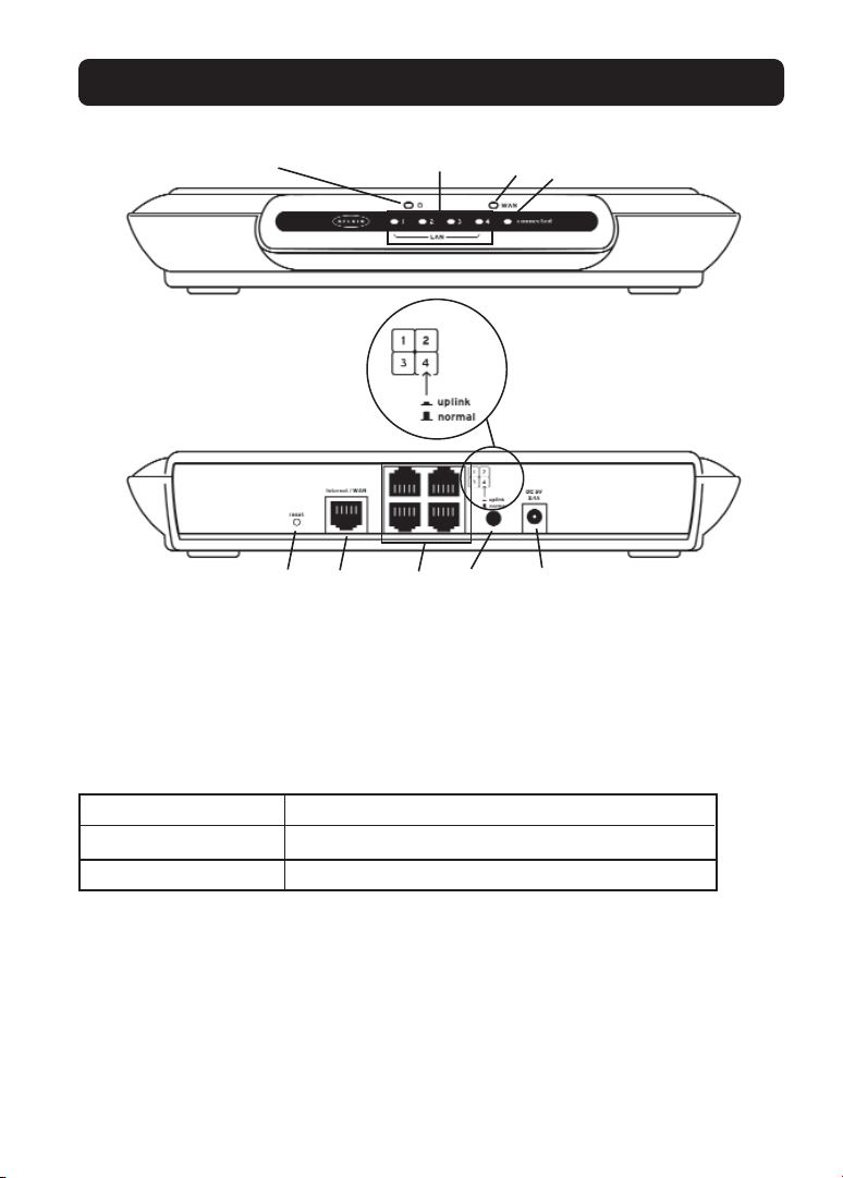
1. Power/Ready LED
When you apply power to the Router or restart it, a short period of time
elapses while the Router boots up. During this time, the “Power/Ready” LED
blinks. When the Router has completely booted up, the Power/Ready LED
becomes a SOLID light, indicating the Router is ready for use.
OFF Router is OFF
Blinking Green Router is Booting Up
Solid Green Router is Ready
2. LAN Port-Status LEDs
These LEDs are labeled 1–4 and correspond to the numbered ports on the rear
of the Router. When a computer is properly connected to one of the LAN ports
on the rear of the Router, the LED will light. GREEN means a 10Base-T device
is connected, AMBER means a 100Base-Tx device is connected. When
information is being sent over the port, the LED blinks rapidly.
OFF No Device is Linked to the Port
Green 10Base-T Device Connected
Orange 100Base-Tx Device Connected
Blinking (Orange or Green) Port Activity
3. WAN Status LED
This LED lights in GREEN to indicate that your modem is connected properly
to the Router. It blinks rapidly when information is being sent over the port
between the Router and the modem.
OFF No WAN Link
Solid Green Good WAN Link
Blinking Green WAN Activity
4
KNOWING YOUR BELKIN ROUTER
(1)
(5)
(6) (7) (8) (9)
(2) (3)
(4)
4. Connected LED
This unique LED shows you when the Router is connected to the Internet.
When the light is OFF, the Router is NOT connected to the Internet. When the
light is blinking, the Router is attempting to connect to the Internet. When
the light is solid GREEN, the Router is connected to the Internet. When using
the “Disconnect after x minutes” feature, this LED becomes extremely useful
in monitoring the status of your Router’s connection.
OFF Router is not Connected to the Internet
Blinking Green Router is Attempting to Connect to the Internet
Solid Green Router is Connected to the Internet
5. Reset Button
The “Reset” button is used in rare cases when the Router may function
improperly. Resetting the Router will restore the Router’s normal operation
while maintaining the programmed settings. You can also restore the factory
default settings by using the Reset button. Use the restore option in
instances where you may have forgotten your custom password.
a. Using the Reset Button to Reset the Router
Push and release the Reset button. The lights on the Router will
5

KNOWING YOUR BELKIN ROUTER
momentarily flash. The Power/Ready light will begin to blink. When the
Power/Ready light becomes solid again, the reset is complete.
b. Using the Reset Button to Restore the Factory Defaults
Press and hold the Reset button for five seconds then release it. The
lights on the Router will momentarily flash. The Power/Ready light will
begin to blink. When the Power/Ready light becomes solid again, the
restore is complete.
6. Internet/WAN Port
This port is for connection to your cable or DSL modem. To ensure proper
functioning, use the cable that was provided with your modem to connect the
modem to this port.
NOTE: Using a cable other than the cable supplied with your cable or DSL
modem may cause malfunctioning.
7. LAN Ports
The LAN ports are RJ45, 10/100 auto-negotiation ports for standard UTP
category 5 or 6 Ethernet cable. The ports are labeled 1–4. These ports
correspond to the numbered LEDs on the front of the Router. Note that
Port 4 can be made into an uplink port. This means that by pressing the
uplink button in, Port 4 will become an uplink port for the addition of a
switch or hub. For more information about the uplink button, see “Uplink
Button” below.
8. Uplink Button
The “Uplink” button is provided for use of Port 4 to connect to a hub or a
switch for expanding the number of network ports on the Router. If you are
connecting a switch or hub to the Router, connect a straight-through
(standard) network cable to this port and to a port on the switch or hub.
Press the Uplink button IN. This will switch Port 4 into an uplink port.
NOTE: If you connect a computer to Port 4, and the link LED for Port 4 will not
turn on, check the Uplink button to make sure that it is in the “Normal”
position (OUT).
9. Power Jack
Connect the included 5V DC power supply to this jack.
6

CONNECTING AND CONFIGURING YOUR CABLE/DSL GATEWAY ROUTER
Verify the contents of your box. You should have the following:
• Belkin Cable/DSL Gateway Router
• Vertical Mounting Base (optional use)
• Category 5 Networking Cable (for connection of the Router to the computer)
• Power Supply
• Belkin Easy Install Wizard Software CD
• User Manual
Modem Requirements
Your cable or DSL modem must be equipped with an RJ45 Ethernet port. Many
modems have both an RJ45 Ethernet port and a USB connection. If you have a
modem with both Ethernet and USB, and are using the USB connection at this
time, you will be instructed to use the RJ45 Ethernet port during the installation
procedure. If your modem has only a USB port, you can request a different type
of modem from your ISP, or you can, in some cases, purchase a modem that has
an RJ45 Ethernet port on it.
Ethernet USB
Easy Install Wizard
Belkin has provided our Easy Install Wizard software to make installing your
Router a simple and easy task. You can use it to get your Router up and running
in minutes. The Easy Install Wizard requires that your Windows 98, Me, 2000, or
XP computer be connected directly to your cable or DSL modem and that the
Internet connection is active and working at the time of installation. If it is not,
you must use the “Alternative Setup Method” section of this manual to configure
your Router. Additionally, if you are using an operating system other than
Windows 98, Me, 2000, or XP, you must set up the Router using the “Alternative
Setup Method” section of this manual.
7
CONNECTING AND CONFIGURING YOUR CABLE/DSL GATEWAY ROUTER
IMPORTANT: Run the Easy Install Wizard from the computer
that is directly connected to the cable or DSL modem.
DO NOT CONNECT THE ROUTER AT THIS TIME.
Step 1: Run the Easy Install Wizard Software
1. Shut down any programs that are running on your computer at this time.
2. Make sure you have the following items at the computer that is now directly
connected to the cable or DSL modem. DO NOT CONNECT THE ROUTER AT
THIS TIME.
• The Easy Install Wizard CD-ROM
• The Router
• The Router power supply
• Category 5 networking cable
• This User Manual
3. Turn off any firewall or Internet connection sharing software on
your computer.
4. Insert the Easy Install Wizard software CD into your CD–ROM Drive. The Easy
Install Wizard screen will automatically appear on your screen within 15
seconds. If it does not, select your CD-ROM drive from “My Computer” and
double-click on the file named “Setup” on the CD-ROM.
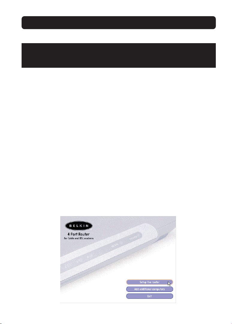
Step 2: Follow the Easy Install Wizard to Complete the Installation
2.1 Click on “Set Up the Router” to begin.
8

CONNECTING AND CONFIGURING YOUR CABLE/DSL GATEWAY ROUTER
2.2 Welcome Screen
The Wizard welcome screen will appear. Make sure you have not connected the
Router at this point. If you have connected your Router, please reconnect your
computer directly to the modem. Click “Next” when you are ready to move on.
2.3 License Agreement
Please read the license agreement in the window. When you are finished, select
“I agree” if you want to continue using the software. Click “I disagree” if you do
not want to continue. Click “Next” to move on.
CORPORATION
Corporation
9

CONNECTING AND CONFIGURING YOUR CABLE/DSL GATEWAY ROUTER
2.4 Examining Settings
The Wizard will now examine your computer’s settings and gather information
needed to complete the Router’s connection to the Internet.
2.5 Multi-NICs Screen
This screen will appear ONLY if you have more than one network adapter
installed in your computer. If you have more than one network adapter installed
in your computer, the Wizard will need to know which adapter is connected to
your modem. Select the network card that is connected to your modem from the
list and click “Next”. If you are not sure which adapter to choose, select the
adapter at the top of the list. If you mistakenly choose the wrong adapter now,
you will be able to choose a different one later.
10
CONNECTING AND CONFIGURING YOUR CABLE/DSL GATEWAY ROUTER
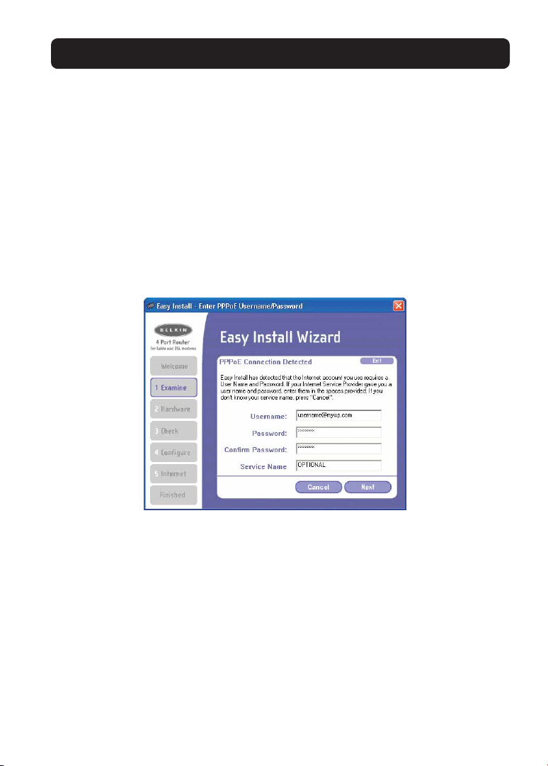
2.6 PPPoE Connection Detected
If you have a connection type that requires a user name and a password, the
Wizard will ask you to type in your user name and password. If your connection
type does not require a user name and password, you will not see this screen.
Your user name and password is provided to you by your Internet Service
Provider. If you have to type in a user name and password to connect to the
Internet, then type that same user name and password in here. Your user name
looks something like “myname@myISP.com” or simply “myname”. The service
name is optional and is very rarely required by your ISP. If you don’t know your
service name, leave this blank. When you have entered your information, click
“Next” to move on.
Step 3: Connect the Router to your Modem and Computer
The Wizard will ask you to connect your Router. Follow the steps on the screen,
or do the following:
3.1 Turn off the power to your modem by unplugging the power supply from
the modem.
3.2 Locate the network cable that is connected between your modem and your
computer and unplug it from your computer, leaving the other end
connected to your modem.
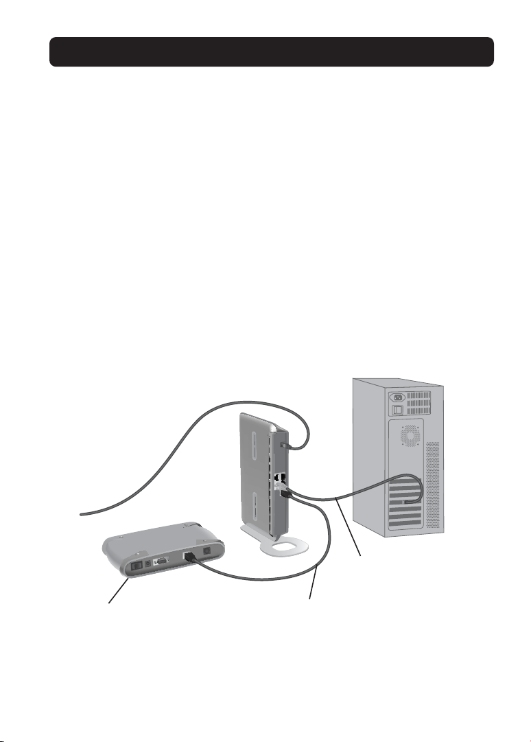
3.3 Plug the loose end of the cable you just unplugged into the port on the back
of the Router labeled “Internet/WAN”.
11
CONNECTING AND CONFIGURING YOUR CABLE/DSL GATEWAY ROUTER
3.4 Connect the new network cable from the back of the computer to one of
the ports labeled “1–4”.
NOTE: It does not matter which numbered port you choose.
3.5 Turn on your cable or DSL modem by reconnecting the power supply to
the modem.
3.6 Before plugging the power cord into the Router, plug the cord into the wall,
then plug the cord into the Router’s power jack.
3.7 Verify that your modem is connected to the Router by checking the lights on
the front of the Router. The green light labeled “WAN” should be ON if your
modem is connected correctly to the Router. If it is not, recheck
your connections.
Computer that was originally
connected to the cable or
DSL modem
To power
adapter
New network cable
(to computer)
Cable or
DSL modem
3.8 Verify that your computer is connected properly to the Router by checking
the lights labeled “LAN 1,2,3,4”. The light which corresponds to the
numbered port that you connected your computer to should be ON if your
computer is connected properly.
Existing network cable
(that came with modem)
12
CONNECTING AND CONFIGURING YOUR CABLE/DSL GATEWAY ROUTER
Step 4: Continue Following the Wizard’s Instructions
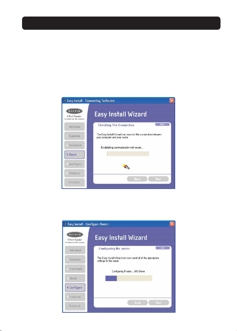
4.1 Checking the Connection
Once you have completed the connection of your Router, the Wizard will check
the connection to the Router. If the Router is not detected, use the
“Troubleshooting” button or refer to the “Troubleshooting” section of this guide
to obtain help about how to correct the problem. If the Wizard is able to
communicate with the Router, the Wizard will move on to the next step.
4.2 Configuring the Router
The Wizard will now transfer all of the configuration information to the Router.
This will take approximately one minute.
13

CONNECTING AND CONFIGURING YOUR CABLE/DSL GATEWAY ROUTER
4.3 When the transfer is complete, the Wizard will tell you that it is done and
may reboot (restart) the Router.
4.4 When configuration is complete, the Wizard will tell you “Router Setup
Complete” and it will move to the next step.
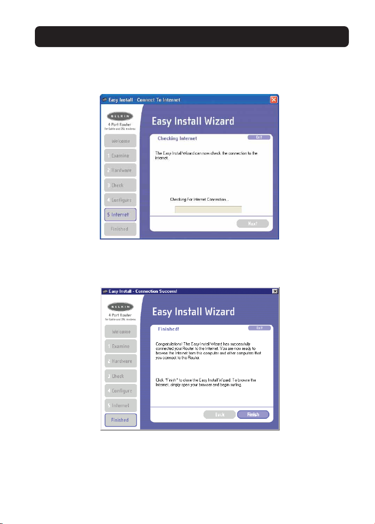
4.5 Checking Internet
The Wizard will now check for an Internet connection. This can take a few
minutes. The Wizard may not detect a connection right away. If not, it will retry
a number of times. The “Connected” light on the front panel of the Router will
flash during this time. Please be patient through this process. If at the end of
this process the Wizard cannot connect to the Internet, use the Troubleshooting
14
CONNECTING AND CONFIGURING YOUR CABLE/DSL GATEWAY ROUTER
button or refer to the Troubleshooting section of this guide to obtain help about
how to correct the problem.
4.6 Finished
When the Internet connection is complete, the Wizard will tell you that you are
finished. The “Connected” LED on the front of the Router will be solid GREEN,
indicating that the Router is now connected to the Internet.
Your Router is now connected to the Internet. Now you can begin surfing the
Internet by opening your browser and going to your favorite web page.
Congratulations! You have finished installing your new Belkin Router. You are
ready to set up the other computers in your home. You can also add computers
to your Router any time you want. Simply follow step 5 to learn how to add
more computers.
15

CONNECTING AND CONFIGURING YOUR CABLE/DSL GATEWAY ROUTER
Step 5: Adding Other Computers to your Network Using the Easy Install Wizard
If you have other computers in your home that are already equipped with a
network adapter, you can use the Easy Install Wizard to set up those computers to
connect to your Router. If you are adding a Belkin network adapter your other
computers, install the adapter per the instructions for the adapter. When the
installation of the adapter is finished, your computer will be set up to connect to
the Router. You do not need to use the Easy Install Wizard to set up the computer.
For Computers Already Equipped with a Network Adapter
5.1 Connect an Ethernet cable between the computer you want to add to the
network and the Router.
5.2 Insert the CD into your CD-ROM drive. The Easy Installation Wizard screen will
automatically pop-up on your screen within 15 seconds. If it does not, select
your CD-ROM drive and double-click on the file named “Setup” on the CD-ROM.
5.3 Click “Add computers”.
5.4 The Wizard will make the changes needed to add your computer to the
network. When finished, it will prompt to reboot your computer. Click “Yes”.
5.5 When your computer reboots, your computer will be connected to the
network. To begin surfing the Internet, open your browser and go to your
favorite web page.
You are finished adding the computer to the network. To add more computers,
repeat this process on each computer you wish to add.
16

17

ALTERNATE SETUP METHOD
Alternate Setup Method
The Advanced User Interface is a web-based tool that you can use to set up the
Router if you don’t want to use the Easy Install Wizard. You can also use it to
manage advanced functions of the Router. From the Advanced User Interface, you
can perform the following tasks:
• View the Router’s current settings and status.
• Configure the Router to connect to your ISP with the settings that they
provided you.
Change the current network settings such as the Internal IP address, the IP
address pool, DHCP settings, and more.
• Set the Router’s firewall to work with specific applications
(port forwarding).
• Set up security features such as client restrictions and MAC
address filtering.
• Enable the DMZ feature for a single computer on your network.
• Change the Router’s internal password.
• Enable/Disable UPnP (Universal Plug-and-Play).
• Reset the Router.
• Back up your configuration settings.
• Reset the Router’s default settings.
• Update the Router’s firmware.
Step 1: Connecting your Gateway/Router
1.1 Turn off the power to your modem by unplugging the power supply
from the modem.
1.2 Locate the network cable that is connected between your modem and your
computer and unplug it from your computer, leaving the other end
connected to your modem.
1.3 Plug the loose end of the cable you just unplugged into the port on the back
of the Router labeled “Internet/WAN”.
1.4 Connect a new network cable (not included) from the back of the
computer to one of the ports labeled “1–4”.
NOTE: It does not matter which numbered port you choose.
1.5 Turn your cable or DSL modem on by reconnecting the power supply to
the modem.
18

ALTERNATE SETUP METHOD
1.6 Before plugging the power cord into the Router, plug the cord into the wall,
then plug the cord into the Router’s power jack.
Mac or PC computer that was
originally connected to the
cable or DSL modem
To power
adapter
Supplied Ethernet
cable (to computer)
Cable or
DSL modem
1.7 Verify that your modem is connected to the Router by checking the lights
on the front of the Router. The green light labeled “WAN” should be ON if
your modem is connected correctly to the Router. If it is not, recheck
your connections.
1.8 Verify that your computer is connected properly to the Router by checking
the lights labeled “LAN 1,2,3,4”. The light which corresponds to the
numbered port connected to your computer should be ON, if your computer
is connected properly. If it is not, recheck your connections.
Step 2: Set your Computer’s Network Settings to Work with a DHCP Server
See the section in this manual called “Manually Configuring Network Settings”
for directions.
Step 3: Configuring the Router Using the Web-Based Advanced User Interface
Using your Internet browser, you can access the Router’s Web-Based Advanced
Existing network cable
(that came with modem)
19

ALTERNATE SETUP METHOD
User Interface. In your browser, type “192.168.2.1” (do not type in anything else
such as “http://” or “www”). Then press the “Enter” key.
Logging into the Router
You will see the Router’s home page in your browser window. The home page is
visible to any user who wants to see it. To make any changes to the Router’s
settings, you have to log in. Clicking the “Login” button or clicking on any one
of the links on the home page will take you to the login screen. The Router ships
with no password entered. In the login screen, leave the password blank and
click the “Submit” button to log in.
Logging out of the Router
One computer at a time can log in to the Router for the purposes of making
changes to the settings of the Router. Once a user has logged in to make
changes, there are two ways that the computer can be logged out. Clicking the
“Logout” button will log the computer out. The second method is automatic. The
login will time out after a specified period of time. The default login time out is
10 minutes. This can be changed from 1 to 99 minutes. For more information,
see the section in this manual titled “Changing the Login Timeout Setting”.
20
 Loading...