

Page 1
User Manual
16-Port Gigabit Switch
24-Port Gigabit Switch
Share large files at faster
network speeds, with
maximum efficiency
F5D5141uk16
F5D5141uk24
SV
FI
DA
NO
PL
CZ
HU
UK
FR
DE
NL
ES
IT
PT
Page 2

1 Introduction. . . . . . . . . . . . . . . . . . . . . . . . . . . . . . . . . . . . . . . . . . . . . . 1
Features . . . . . . . . . . . . . . . . . . . . . . . . . . . . . . . . . . . . . . . . . . . . . .
2
Package Contents . . . . . . . . . . . . . . . . . . . . . . . . . . . . . . . . . . . . . .
2
2 Getting to Know your Switch. . . . . . . . . . . . . . . . . . . . . . . . . . . . . . . . 3
3 Connecting Networking Devices to your Switch. . . . . . . . . . . . . . . . 4
4 Applications. . . . . . . . . . . . . . . . . . . . . . . . . . . . . . . . . . . . . . . . . . . . . . 6
5 Placement of the Switch . . . . . . . . . . . . . . . . . . . . . . . . . . . . . . . . . . . 7
6 Product Specifications . . . . . . . . . . . . . . . . . . . . . . . . . . . . . . . . . . . . . 8
7 Troubleshooting . . . . . . . . . . . . . . . . . . . . . . . . . . . . . . . . . . . . . . . . . 10
8 Information . . . . . . . . . . . . . . . . . . . . . . . . . . . . . . . . . . . . . . . . . . . . . 12
Table of Contents
Page 3

Introduction
section
1
2
3
4
5
6
7
8
Congratulations on your purchase of this high-quality Belkin 16- or
24-Port Gigabit Switch. Backward-compatible with 10/100 networks,
each Switch easily integrates into a new or existing network for
instant high performance. It delivers dedicated 100Mbps links to
each directly attached LAN segment or PC, enabling your servers
and workstations to transfer large AV and graphic files efficiently
throughout your network. This makes the Switch an excellent way to
increase the throughput of interconnected Ethernet and Fast Ethernet
hubs or server farms.
Engineered for compact convenience, each Switch features a durable
metal chassis that can be placed on the desktop or integrated
into a 19-inch rack, using the included rack-mount kit. All ports
auto-negotiate between a 10-, 100-, or 1000Mbps network and
adjust for straight-through or crossover cables, so you don’t have
to worry about cable type.
1
Page 4

Getting to Know your Switch
Features
- High-speed, dedicated 10/100/1000 Ethernet ports
• 16 ports (Belkin 16-Port Gigabit Switch F5D5141-16)
• 24 ports (Belkin 24-Port Gigabit Switch F5D5141-24)
- Standards
• IEEE 802.3 z/ab 1000Base-T
• IEEE 802.3u 100Base-Tx
• IEEE 802.3 10Base-T
- Place on your desk or 19-inch rack
- Internal power supply (100–240VAC/50–60Hz universal input)
- Auto MDI/MDIX ports
- Auto-negotiation between 10-, 100-, and 1000Mbps on all ports
- Auto-negotiation for full and half duplex on all ports
- Collision detection on all ports
- IEEE 802.3x PAUSE frames flow control in full-duplex operation
- Back-pressure flow control in half-duplex operation
- Support for up to 8K MAC address entries
- A Belkin Limited Lifetime Warranty and free, 24-hour
technical support
Package Contents
• Belkin 16- or 24-Port Gigabit Switch
• AC Power Cord
• Kit for 19
• Self-Adhesive Rubber Pads for Desktop
• User Manual
" Rack Installation
Page 5
3
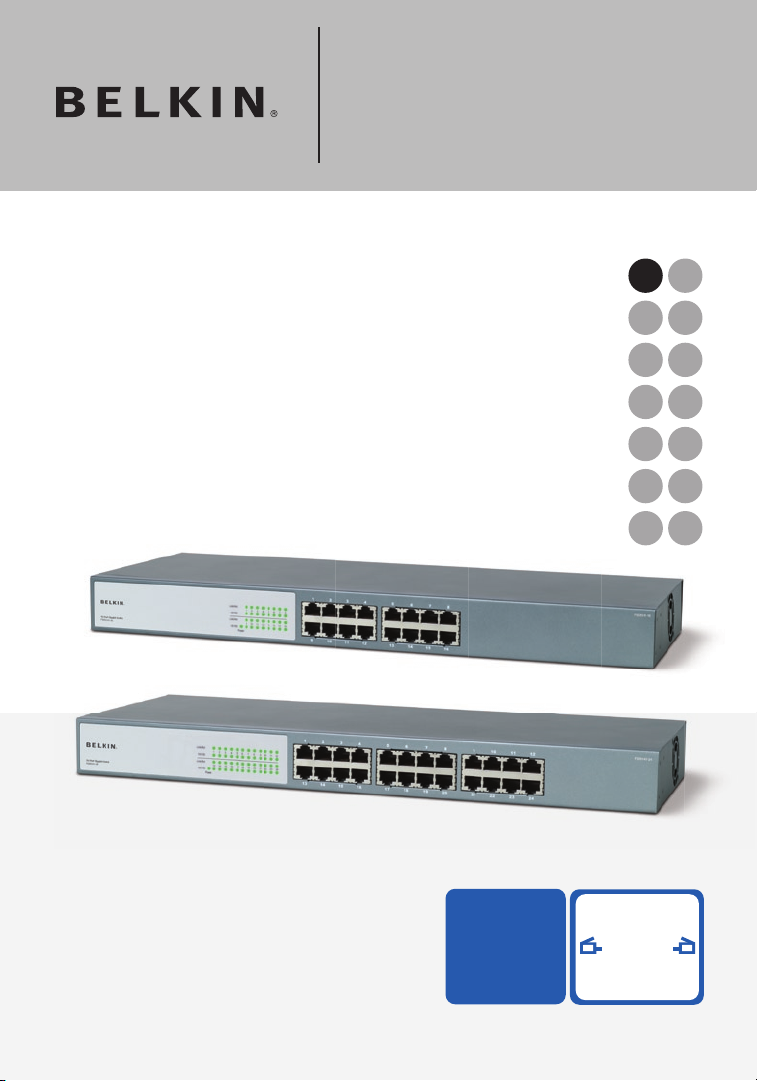
Front-Panel LEDs
Belkin 16- or 24-Port Gigabit Switches feature two rows of LEDs
that provide information about connection speed, link/activity, plus
a separate Power LED.
(a) Power (POWER) LED
• Green – Power on, normal operation
• Off – Power off, no power to the Switch
(b) Link and Activity (Link/Act) LED
• Solid Green – Network device is correctly connected to the
Switch through this port
• Blinking Green – Data is being transmitted and received
through this port
• Off – No link is established
(c) 100M/1000M LED
• Solid Green – A valid 1000Mbps link is established on
the port
• Solid Yellow – A valid 100Mbps link is established on
the port
• Off – A valid 10Mbps link is established on the port
(b)
(c)
(a)
Getting to Know your Switch
3
section
1
2
3
4
5
6
7
8
Page 6
Connecting Networking Devices to your Switch
54
Connecting your Switch to your Computers
1. Power down all your equipment.
2. Connect a Category 5e or 6 Ethernet cable between each
computer’s network interface card (NIC) and one of the
numbered ports on the front of the Switch.
3. All switch ports can automatically negotiate speeds at full- and
half-duplex modes to allow users to attach 10Base-T,
100Base-Tx, and 1000Base-T network devices.
4. Connect the power cord into the power socket in the rear of the
Switch; now plug the other end of the power cord into a power
source (wall jack or power strip).
Page 7

5
Connecting Networking Devices to your Switch
5
section
1
2
3
4
5
6
7
8
Connecting your Switch to another Switch
1. Connect a Category 5e or 6 cable between one of the numbered
ports on the front of the Switch and one of the numbered ports
on the other Switch to which you are cascading or connecting.
2. All switch ports can automatically negotiate speeds at
full-and half-duplex modes to allow users to attach 10Base-T,
100Base-Tx, and 1000Base-T network switches or hubs.
3. All ports support auto MDI and MDIX functionality. When
cascading or connecting switches or hubs, the user can use a
straight-through or crossover cable.
Important: When connecting two switches together, use a single
cable. If multiple cables are used, loops may occur resulting in
unwanted collisions. This will result in poor network performance.
Cabling Distances
• 328 ft. (100m)
Recommended Cabling Standard
• Category 5e or 6 for Gigabit connections (1000Mbps)
• Category 5 for Ethernet (10Mbps) and Fast Ethernet
connections (100Mbps)
Page 8

Applications
This Switch segments your network, significantly increasing both
bandwidth and throughput. Each port on the Switch can be attached
to any Ethernet, Fast Ethernet, or Gigabit Ethernet device, such as
another switch, or a server’s network adapter. All ports operate at
10/100Mbps full and half duplex, or 1000Mbps full duplex, providing
up to 2Gbps of bandwidth to the attached device.
Bridging Functions
This Switch provides fully transparent bridging functions. It
automatically learns node addresses that are subsequently used to
filter and forward all traffic based on the destination address. When
traffic passes between devices attached to the same shared collision
domain, those packets are filtered from the Switch. But when traffic
must be passed between unique segments (i.e., different ports on the
Switch), the high-speed switching fabric forwards the packets at
near-zero latency.
Switching Functions
Store-and-forward switching is used to forward traffic to other ports.
This scheme ensures data integrity and provides a clean data stream.
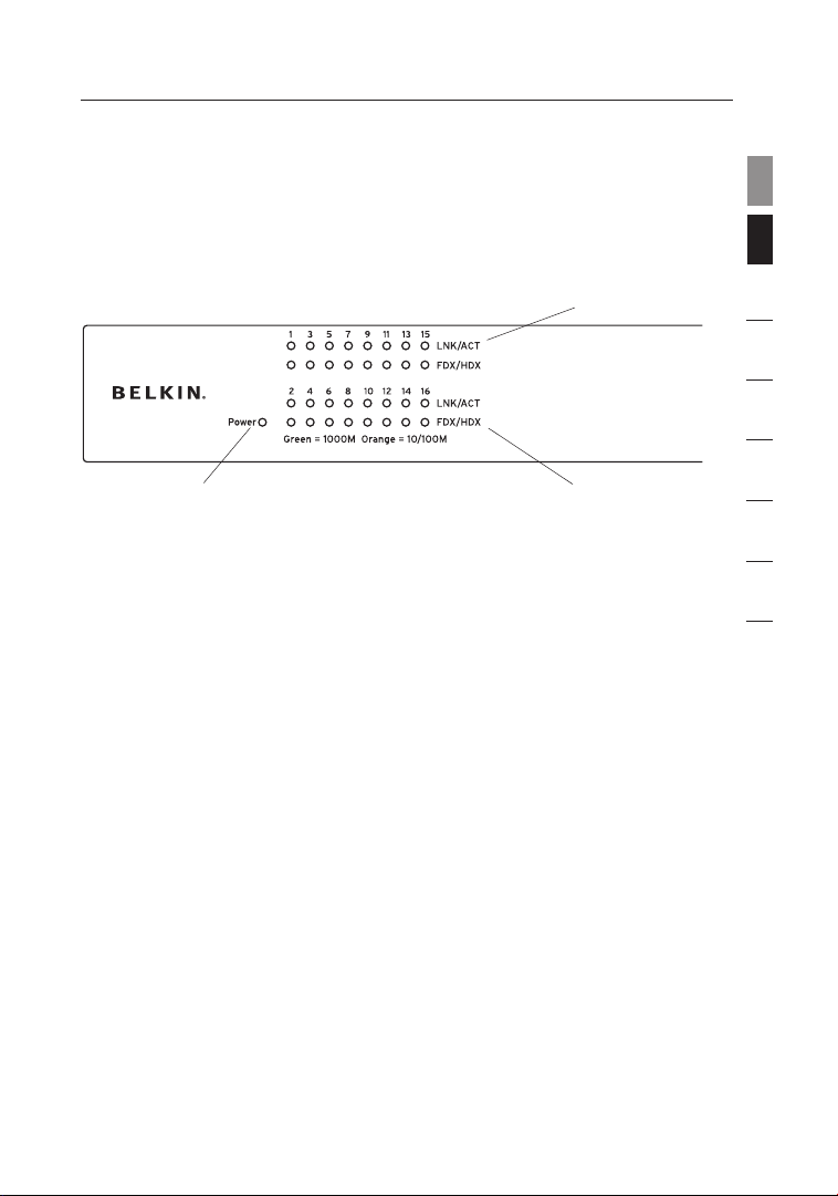
Sample Application
This Switch is designed to operate as a small workgroup switch. It
can provide 10-, 100-, or 1000Mbps connections to workstations, or
1000Mbps full-duplex links to high-speed servers. It can also provide
a high-bandwidth uplink to the network backbone.
Page 9

7
The Switches can be placed on a flat surface or in a 19-inch rack.
Placement on a Flat Surface
1. Affix the four included rubber feet on the bottom of the Switch in
the area that is clearly marked on each of the four corners.
2. Make sure the Switch is placed in an area that allows for
proper ventilation.
3. Place on a flat surface.
Placement in a 19-Inch Rack
1. Do not affix the four rubber feet on the Switch when
rack-mounting. If already affixed, remove.
2. Attach the mounting bracket to each side of the Switch with
the included screws.
3. Place the Switch in the rack and align the holes of the mounting
bracket with the correct hole in the rack.
4. Place and tighten the screws of each mounting bracket into
the rack.
Placement of the Switch
7
section
1
2
3
4
5
6
7
8
Page 10
Product Specifications
98
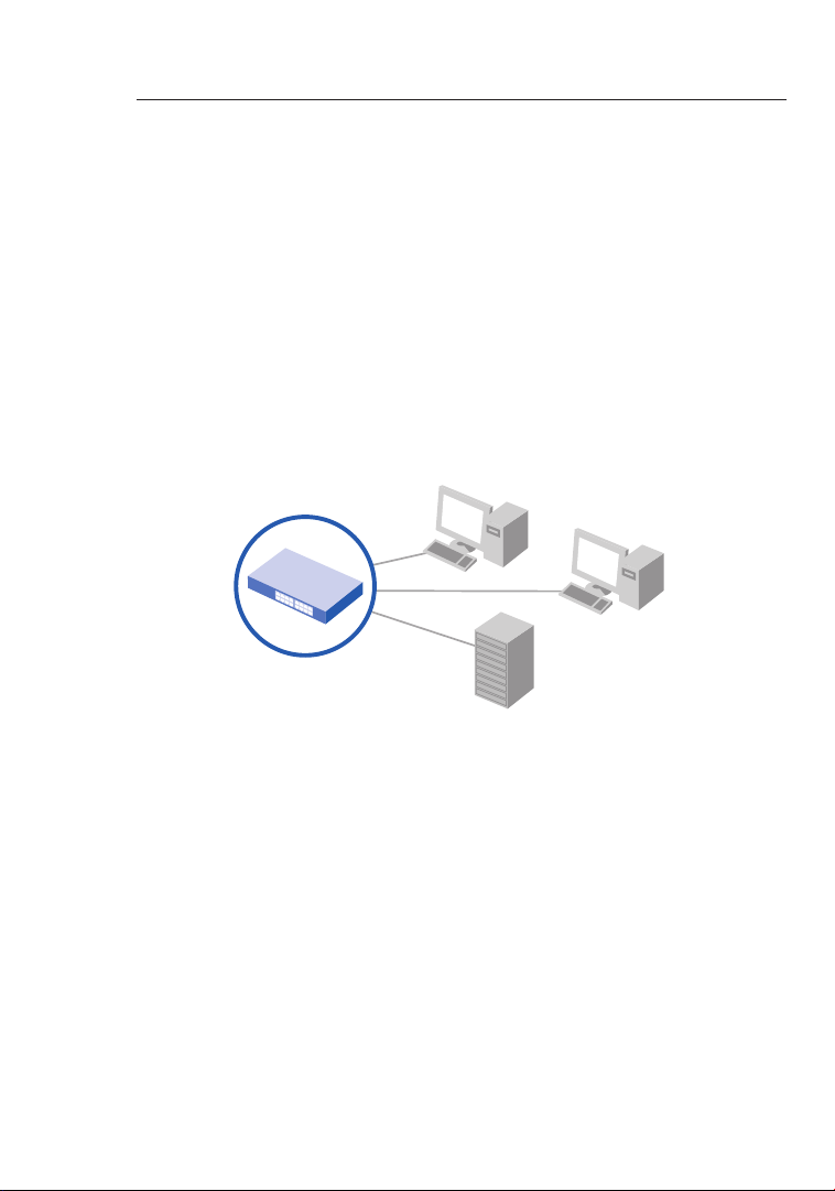
Physical Characteristics
Standards Conformance IEEE Std 802.3-2002
Communication Rate 10-, 100-, and 1000Mbps
Communication Mode Full or half duplex at 10/100Mbps
Full duplex at 1000Mbps
Media Supported 10Base-T: 100-Ohm Category 3 or
better twisted-pair
100Base-Tx: 100-Ohm Category 5 or
better twisted-pair
1000Base-T: 100-Ohm Category 5, 5e,
or 6 twisted-pair
Number of Ports F5D5141-16: 16 RJ45 1000Base-T ports
F5D5141-24: 24 RJ45 1000Base-T ports
Indicator Panel Power
Ports: Link/Act & 100M/1000M
Power Requirement Input Voltage: 100–240V AC @ 50–60Hz
Power Consumption 28W maximum
Temperature Operating: 0 ~ 40
˚ C (32 ~ 98˚ F)
Storage: -40 ~ 70
˚ C (-40 ~ 158˚ F)
Humidity 10% to 90% non-condensing
Immunity EN 61000-4-2/3/4/5/6/8/11
Emissions FCC Class A, CISPR Class A,
EN 61000-3-2/3
Safety CSA/CUS (CSA 60950-1 & UL 60950-1)
TÜV/GS (EN 60950-1) CB (IEC 60950-1)
Physical Dimensions 17.32 x 6.77 x 1.69 in. (44 x 17.1 x 4.4cm)
Page 11

9
Product Specifications
9
section
1
2
3
4
5
6
7
8
Switching Criteria
Network Bridging Function Filtering, forwarding, and learning
Switching Method Store-and-forward
MAC Address Table F5D5141-16: 8K entries
F5D5141-24: 8K entries
Packet Buffer F5D5141-16: 320Kb
F5D5141-24: 480Kb
Page 12

Troubleshooting
1110
Diagnosing Switch Indicators
Symptom
Power LED does not light after power on.
Probable Causes
AC power cord may be defective.
Possible Solutions
• Check for loose connections.
• Check the power outlet by using it for another device.
• Replace the AC power cord.
Symptom
Port (Link/Act) LED does not light after connection is made.
Probable Causes
Switch port, network card, or cable may be defective.
Possible Solutions
• Check that the Switch and attached device are both
powered on.
• Be sure the network cable is connected to both devices.
• Verify that Category 5 or better cable is used for 10/100Mbps
connections; Category 5, 5e, or 6 cable for 1000Mbps
connections; and that the length of any cable does not
exceed 328 feet (100m).
• Check the network card and cable connections for defects.
• Replace the defective card or cable if necessary.
Page 13

11
Troubleshooting
Installation
Verify that all system components have been properly
installed. If one or more components (e.g., the power cord or
network cabling) appear to be malfunctioning, test them in an
alternate environment where you are sure that all the other
components are functioning properly.
Free Tech Support*
*National call rates may apply
Country Number Internet adress
AUSTRIA
CZECH REPUBLIC
DENMARK
FINLAND
FRANCE
GERMANY
GREECE
HUNGARY
ICELAND
IRELAND
ITALY
LUXEMBOURG
NETHERLANDS
NORWAY
POLAND
PORTUGAL
RUSSIA
SOUTH AFRICA
SPAIN
SWEDEN
SWITZERLAND
UK
08 - 20 20 07 66
23 900 0 4 06
701 22 4 03
008 00 - 22 35 54 6 0
08 - 25 54 00 26
018 0 - 5 00 57 09
008 00 - 44 14 23 9 0
06 - 17 77 49 06
800 8534
081 8 55 50 06
02 - 69 43 02 51
34 20 80 8560
090 0 - 0 40 07 90
815 00 2 87
008 00 - 441 1 7 37
707 200 676
495 580 9541
080 0 - 9 9 15 21
90 - 202 43 6 6
07 - 71 40 04 53
08 - 48 00 02 19
084 5 - 6 07 77 87
http://w ww.belkin.com /uk/networkin g/
http://w ww.belkin.com /uk/networkin g/
http://w ww.belkin.com /uk/networkin g/
http://w ww.belkin.com /uk/networkin g/
http://w ww.belkin.com /fr/networkin g/
http://w ww.belkin.com /de/networkin g/
http://w ww.belkin.com /uk/networkin g/
http://w ww.belkin.com /uk/networkin g/
http://w ww.belkin.com /uk/networkin g/
http://w ww.belkin.com /uk/networkin g/
http://w ww.belkin.com /it/support/t ech/issues_mo re.asp
http://w ww.belkin.com /uk/networkin g/
http://w ww.belkin.com /nl/networkin g/
http://w ww.belkin.com /uk/networkin g/
http://w ww.belkin.com /uk/networkin g/
http://w ww.belkin.com /uk/networkin g/
http://w ww.belkin.com /networking/
http://w ww.belkin.com /uk/networkin g/
http://w ww.belkin.com /es/support/t ech/networkin gsupport.asp
http://w ww.belkin.com /se/support/t ech/networkin gsupport.asp
http://w ww.belkin.com /uk/networkin g/
http://w ww.belkin.com /uk/networkin g/
1
2
3
4
5
6
section
7
8
Before you Call
If possible, turn on your system before you call Belkin for
technical assistance and call from a telephone at or near the
computer. You may be asked to describe detailed information
during operation.
11
Page 14

Information
1312
EMI Certification
FCC Class A Certification (USA)
This equipment has been tested and found to comply with the limits
for a Class A digital device, pursuant to Part 15 of the FCC Rules.
These limits are designed to provide reasonable protection against
harmful interference in a residential installation. This equipment
generates, uses, and can radiate radio frequency energy and, if not
installed and used in accordance with instructions, may cause harmful
interference to radio communications. However, there is no guarantee
that the interference will not occur in a particular installation. If this
equipment does cause harmful interference to radio or television
reception, which can be determined by turning the equipment off and
on, the user is encouraged to try to correct the interference by one or
more of the following measures:
• Reorient the receiving antenna
• Increase the separation between the equipment and receiver
• Connect the equipment into an outlet on a circuit different
from that to which the receiver is connected
• Consult the dealer or an experienced radio/TV technician
for help
Industry Canada – Class A
This digital apparatus does not exceed the Class A limits for radio
noise emissions from digital apparatus as set out in the interferencecausing equipment standard entitled “Digital Apparatus,” ICES-003 of
the Department of Communications.
CE Mark Declaration of Conformance for EMI and Safety (EEC)
This information technology equipment complies with the
requirements of the Council Directive 89/336/EEC on the
Approximation of the laws of the Member States relating to
Electromagnetic Compatibility and 73/23/EEC for electrical equipment
used within certain voltage limits and the Amendment Directive 93/68/
EEC. For the evaluation of the compliance with these Directives, the
following standards were applied:
Page 15

13
Information
13
section
1
2
3
4
5
6
7
8
RFI Emission:
• Limit class A according to EN 55022:1998, IEC 60601-1-2
(EMC, medical)
• Limit class A for harmonic current emission according to
EN 61000-3-2/1995
• Limitation of voltage fluctuation and flicker in low-voltage supply
system according to EN 61000-3-3/1995
Immunity:
• Product family standard according to EN 55024:1998
• Electrostatic Discharge according to EN 61000-4-2:1995
(Contact Discharge: ±4kV, Air Discharge: ±8kV)
• Radio-frequency electromagnetic field according to EN 61000-43:1996 (80–1000MHz with 1kHz AM 80% Modulation: 3V/m)
• Electrical fast transient/burst according to EN 61000-4-4:1995
(AC/DC power supply: ±1kV, data/signal lines: ±0.5kV)
• Surge immunity test according to EN 61000-4-5:1995 (AC/DC line
to line: ±1kV, AC/DC line to earth: ±2kV)
• Immunity to conducted disturbances, induced by radio-frequency
fields: EN 61000-4-6:1996 (0.15–80MHz with 1kHz AM 80%
modulation: 3V/m)
• Power frequency magnetic field immunity test according to EN
61000-4-8:1993 (1A/m at frequency 50Hz)
• Voltage dips, short interruptions, and voltage variations immunity
test according to EN 61000-4-11:1994 (>95% reduction @ 10ms,
30% reduction @ 500ms, >95% reduction @ 5000ms)
LVD:
• EN 60950-1:2001
Page 16

Information
1514
Safety Compliance
Please read the following safety information carefully before installing
the Switch:
Warning: Do not plug a phone-jack connector into the RJ45 port. This
may damage this device.
Warning: This product does not contain any user-serviceable parts.
Warning: When connecting this device to a power outlet, connect
the field ground lead on the tri-pole power plug to a valid earth
ground AC-outlet line to prevent electrical hazards and to comply with
international safety standards. The appliance coupler (the connector
to the unit and not the wall plug) must have a configuration for mating
with an EN 60320/IEC 320 appliance inlet. The socket outlet must be
near to the unit and easily accessible. You can only remove power
from the unit by disconnecting the power cord from the outlet.
Caution:
Use only twisted-pair cables with RJ45 connectors that
conform to FCC standards.
Wear an anti-static wrist strap or take other suitable measures to
prevent electrostatic discharge when handling this equipment.
This unit operates under SELV (Safety Extra Low Voltage) conditions
according to IEC 60950. The conditions are only maintained
if the equipment to which it is connected also operates under
SELV conditions.
Page 17

15
Information
15
1
2
3
4
5
6
7
8
section
Belkin Corporation Limited Lifetime Product Warranty
What this warranty covers.
Belkin Corporation warrants to the original purchaser of this Belkin
product that the product shall be free of defects in design, assembly,
material, or workmanship.
What the period of coverage is.
Belkin Corporation warrants the Belkin product for the lifetime of the product.
What will we do to correct problems?
Product Warranty.
Belkin will repair or replace, at its option, any defective product free of charge
(except for shipping charges for the product).
What is not covered by this warranty?
All above warranties are null and void if the Belkin product is not provided to
Belkin Corporation for inspection upon Belkin’s request at the sole expense
of the purchaser, or if Belkin Corporation determines that the Belkin product
has been improperly installed, altered in any way, or tampered with. The
Belkin Product Warranty does not protect against acts of God (other than
lightning) such as flood, earthquake, war, vandalism, theft, normal-use wear
and tear, erosion, depletion, obsolescence, abuse, damage due to low
voltage disturbances (i.e. brownouts or sags), non-authorized program, or
system equipment modification or alteration.
How to get service.
To get service for your Belkin product you must take the following steps:
1. Contact Belkin Corporation at 501 W. Walnut St., Compton CA 90220,
Attn: Customer Service, or call (800)-223-5546, within 15 days of the
Occurrence. Be prepared to provide the following information:
a. The part number of the Belkin product.
b. Where you purchased the product.
c. When you purchased the product.
d. Copy of original receipt.
2. Your Belkin Customer Service Representative will then instruct you on
how to forward your receipt and Belkin product and how to proceed with
your claim.
Page 18

Information
1716
Belkin Corporation reserves the right to review the damaged Belkin product.
All costs of shipping the Belkin product to Belkin Corporation for inspection
shall be borne solely by the purchaser. If Belkin determines, in its sole
discretion, that it is impractical to ship the damaged equipment to Belkin
Corporation, Belkin may designate, in its sole discretion, an equipment repair
facility to inspect and estimate the cost to repair such equipment. The cost,
if any, of shipping the equipment to and from such repair facility and of such
estimate shall be borne solely by the purchaser. Damaged equipment must
remain available for inspection until the claim is finalized. Whenever claims
are settled, Belkin Corporation reserves the right to be subrogated under any
existing insurance policies the purchaser may have.
How state law relates to the warranty.
THIS WARRANTY CONTAINS THE SOLE WARRANTY OF BELKIN
CORPORATION, THERE ARE NO OTHER WARRANTIES, EXPRESSED
OR, EXCEPT AS REQUIRED BY LAW, IMPLIED, INCLUDING THE IMPLIED
WARRANTY OR CONDITION OF QUALITY, MERCHANTABILITY OR FITNESS
FOR A PARTICULAR PURPOSE, AND SUCH IMPLIED WARRANTIES, IF
ANY, ARE LIMITED IN DURATION TO THE TERM OF THIS WARRANTY.
Some states do not allow limitations on how long an implied warranty lasts,
so the above limitations may not apply to you.
IN NO EVENT SHALL BELKIN CORPORATION BE LIABLE FOR INCIDENTAL,
SPECIAL, DIRECT, INDIRECT, CONSEQUENTIAL OR MULTIPLE DAMAGES
SUCH AS, BUT NOT LIMITED TO, LOST BUSINESS OR PROFITS ARISING
OUT OF THE SALE OR USE OF ANY BELKIN PRODUCT, EVEN IF ADVISED
OF THE POSSIBILITY OF SUCH DAMAGES.
This warranty gives you specific legal rights, and you may also have other
rights, which may vary from state to state. Some states do not allow the
exclusion or limitation of incidental, consequential, or other damages, so the
above limitations may not apply to you.
Page 19

17
Information
17
1
2
3
4
5
6
7
8
section
Following information is only for EU-member states:
The use of the symbol indicates that this product may not be treated as
household waste. By ensuring this product is disposed of correctly, you will
help prevent potential negative consequences for the environment and human
health, which could otherwise be caused by inappropriate waste handling of
this product. For more detailed information about recycling of this product,
please visit our web at www.belkin.com (or contact your local city office,
your household waste disposal service or the shop where you purchased the
product)
Page 20

F5D5141fr16
F5D5141fr24
SV
FI
DA
NO
PL
CZ
HU
UK
FR
DE
NL
ES
IT
PT
Partagez des fi chiers
volumineux sur des réseaux
plus rapides
avec une effi cacité maximale
Manuel de
l’utilisateur
Switch Gigabit à 16 Ports
Switch Gigabit à 24 Ports
Page 21

Table des matières
1 Introduction .................................................................................... 1
Caractéristiques .................................................................................
Contenu de l’emballage ....................................................................
2 Présentation du switch .................................................................. 3
3 Branchement de vos dispositifs sur votre switch ...................... 4
4 Applications .................................................................................... 6
5 Choix de l’emplacement du switch .............................................. 7
6 Caractéristiques techniques du produit ...................................... 8
7 Dépannage .................................................................................... 10
8 Information .................................................................................... 12
2
2
Page 22

Introduction
section
1
2
3
4
5
6
7
8
Félicitations! Vous avez fait l’achat du Switch Gigabit à 16 ou 24
ports de Belkin. Compatible avec les réseaux 10/100, ce switch
s’intègre parfaitement à un nouveau réseau ou un réseau existant.
Il offre une liaison de 100 Mbps à chaque segment du réseau LAN
ou chaque PC, permettant à vos serveurs et postes de travail de
transférer des fichiers audio/vidéo ou images efficacement grâce
à votre réseau. Le Switch représente ainsi une excellente solution
pour augmenter le débit et la performance des hubs ou des parcs de
serveurs Ethernet et Fast Ethernet.
Conçu pour s’installer et s’utiliser de façon conviviale, le Switch
possède un boîtier métallique résistant et peut être placé sur un
bureau ou monté dans une baie de 19 pouces au moyen du kit de
montage en baie. Chaque port auto-négocie et auto-détecte un
réseau 10/100/1000 Mbps et s’ajuste automatiquement aux câbles
réseau intermédiaires ou inverseurs : nul besoin de vous préoccuper
du type de câble.
1
Page 23

Présentation du switch
Caractéristiques
• Ports Ethernet 10/100/1000 à haut débit
• 16 ports (Switch réseau à 16 ports Belkin F5D5141-16)
• 24 ports (Switch réseau à 24 ports Belkin F5D5141-24)
• Normes
• IEEE 802.3 z/ab 1000Base-T
• IEEE 802.3u 100Base-Tx
• IEEE 802.3 10Base-T
• Boîtier de 1U, pouvant être placé sur un bureau ou monté dans
une baie de 19 pouces
• Source d’alimentation interne (entrée universelle 100 – 240 VCA /
50 – 60 Hz)
• Ports MDI/MDIX automatiques
• Négociation automatique 10/100/1000 Mbps sur chaque port
• Négociation automatique duplex intégral ou semi-duplex sur
chaque port
• Détection de collisions sur chaque port
• Contrôle de flux « Pause Frames » IEEE 802.3x en mode duplex
intégral
• Contrôle du flux par contre-pression lors du fonctionnement en
mode semi-duplex
• Prise en charge de 8000 adresses MAC
• Garantie à vie limitée de Belkin et assistance technique gratuite
Contenu de l’emballage
• Switch réseau Gigabit à 16 ou à 24 ports de Belkin
• Cordon d’alimentation CA
• Kit de montage en baie de 19
”
• Coussinets en caoutchouc adhésifs pour installation sur une
surface de travail
• Manuel de l’utilisateur
Page 24

3
Témoins de la face avant
Les Switchs Gigabit à 16 ou 24 ports de Belkin possèdent deux
rangées de témoins, vous informant à propos du débit de connexion,
la liaison et l’activité, ainsi qu’un témoin d’alimentation.
(a) Témoin d’alimentation (POWER)
• Vert – Sous tension, fonctionnement normal
• Éteint – Hors tension, le switch n’est pas alimenté
(b) Témoin Liaison/Activité (Link/Act)
• Vert continu – Dispositif réseau connecté au port
• Vert clignotant – Transmission de données au port
• Éteint – Aucune liaison n’est établie
(c) Témoin 100 M/1000 M
• Vert continu – Une liaison 1000 Mbps est établie à ce port
• Vert continu – Une liaison 1000 Mbps est établie à ce port
• Éteint – Une liaison 10 Mbps est établie à ce port
(b)
(c)
(a)
Présentation du switch
3
section
1
2
3
4
5
6
7
8
Page 25

Branchement de vos dispositifs sur votre switch
54
Branchement du switch sur les ordinateurs
1. Mettez tout l’équipement hors tension.
2. Branchez un câble Ethernet de Catégorie 5e ou 6 entre chaque
carte d’interface réseau (CIR) des ordinateurs et l’un des ports
numérotés à l’avant du switch.
3. Tous les ports du switch peuvent autonégocier le débit et le
mode duplex (duplex intégral ou semi-duplex) afin de permettre
aux utilisateurs d’y relier des dispositifs réseau 10/100/1000
Base-Tx.
4. Branchez le cordon d’alimentation dans la prise prévue à cet
effet à l’arrière du switch. Branchez maintenant l’adaptateur sur
une source électrique (prise secteur murale ou bloc multiprise).
Page 26

5
Branchement de vos dispositifs sur votre switch
5
section
1
2
3
4
5
6
7
8
Branchement du switch sur un autre switch
1. Branchez un câble Ethernet de catégorie 5e ou 6 entre l’un des
ports numérotés à l’avant du switch et l’un des ports numérotés
de l’autre switch avec lequel vous désirez réaliser un montage en
série ou sur lequel vous désirez le brancher.
2. Tous les ports du switch peuvent autonégocier le débit et le
mode duplex (duplex intégral ou semi-duplex) afin de permettre
aux utilisateurs d’y relier des switchs ou hubs 10/100/1000 BaseTx.
3. Tous les ports prennent en charge la fonction MDI/MDIX.
Lorsque vous montez en série ou branchez des switchs ou des
hubs, vous pouvez utiliser un câble intermédiaire ou inverseur.
Important : Lorsque vous reliez deux switchs ensemble,
n’utilisez qu’un seul câble. Si vous utilisez plusieurs câbles, des
boucles peuvent survenir et ainsi causer des collisions. Ceci
entraîne des performances réseau médiocres.
Distances de câblage
• 100 mètres
Catégorie de câbles recommandée
• Catégorie 5e ou 6 pour les connexions Gigabit (1000 Mbps)
• Catégorie 5 ou 6 pour les connexions Ethernet (10 Mbps) et
le Fast Ethernet (100 Mbps)
Page 27

Applications
Le switch segmente votre réseau, ce qui augmente la bande passante
et la performance. Chaque port du switch peut être relié à un
dispositif Ethernet, Fast Ethernet ou Gigabit Ethernet, tel qu’un switch
ou l’adaptateur réseau d’un serveur. Tous les ports fonctionnent
en mode duplex intégral et semi-duplex à 10/100 Mbps ou duplex
intégral à 1000 Mbps, procurant une bande passante allant jusqu’à
2 Gbps au dispositif qui y est relié.
Fonctions de pontage
Ce switch offre des fonctions de pontage entièrement transparentes.
Il apprend automatiquement les adresses des nœuds, qui sont
ensuites utilisées pour le filtrage et la retransmission du trafic de
données vers l’adresse de destination. Lorsque les données transitent
entre les dispositifs reliés au même domaine de collision partagé, ces
paquets sont filtrés par le switch. Cependant, lorsque les données
doivent transiter entre des segments uniques, c’est à dire des ports
différents sur le switch, la matrice de commutation à haut débit
retransmet les paquets avec un temps de retard presque nul.
Fonctions de commutation
La commutation en mode différé est utilisée pour retransmettre le
trafic de données aux autres ports. Ce mécanisme garantit l’intégrité
des données et procure un flux de données continu.
Applications
Ce switch est conçu pour opérer dans un petit réseau de travail. Il
offre une connexion à 10, 100 ou 1000 Mbps aux postes de travail ou
une liaison à duplex intégral de 1000 Mbps aux serveurs haut débit.
Il offre également une liaison haut débit en amont vers la dorsale du
réseau.
Page 28

7
Les switchs peuvent être placés sur une surface plane ou dans une
baie de 19 pouces.
Placement sur une surface plane
1. Apposez les quatre coussinets fournis avec votre switch sous
celui-ci, aux quatre coins, aux endroits clairement indiqués.
2. Assurez-vous que votre Switch est placé dans un endroit
permettant une ventilation adéquate.
3. Placez-le sur une surface plane.
Placement dans une baie de 19 pouces
1. N’apposez pas les quatre coussinets sur le switch lorsque vous le
montez dans une baie. S’ils sont déjà en place, retirez-les.
2. Fixez les supports de montage de chaque côté du switch, à l’aide
des vis fournies.
3. Placez le switch dans la baie, et alignez les trous du support de
montage avec les trous correspondants de la baie.
4. Placez et serrez les vis de chaque support de montage dans la
baie.
Choix de l’emplacement du switch
7
section
1
2
3
4
5
6
7
8
Page 29

Caractéristiques techniques du produit
98
Caractéristiques physiques
Conformité IEEE 802.3-2002
Débit de communication 10, 100 et 1000 Mbps
Mode de communication Duplex intégral ou semi-duplex à
10/100 Mbps
Duplex intégral à 1000 Mbps
Câbles pris en charge 10Base-T : Paires torsadées 100 Ohm
de catégorie 3 ou mieux
100Base-Tx : Paires torsadées 100 Ohm
de catégorie 5 ou mieux
1000Base-Tx : Paires torsadées 100 Ohm
de catégorie 5, 5e ou 6
Nombre de ports F5D5141-16 : 16 ports RJ45 1000Base-Tx
F5D5141-24 : 24 ports RJ45 1000Base-Tx
Panneau à voyants Ports d’alimentation : Liaison/activité et
100 M/1000 M
Alimentation Tension d’entrée : 100 - 240 VAC, 50-60 Hz
Consommation électrique 28 W maximum
Température Fonctionnement : 0 ~ 40 °C
Stockage : -40 ~ 70 °C
Humidité 10 % à 90 % sans condensation
Immunité EN 61000-4-2/3/4/5/6/8/11
Émission FCC Classe A, CISPR Classe A, EN 61000-
3-2/3
Sécurité CSA/CUS (CSA 60950-1 & UL 60950-1)
TÜV/GS (EN 60950-1) CB (IEC 60950-1)
Page 30

9
Caractéristiques techniques du produit
9
section
1
2
3
4
5
6
7
8
Critères de commutation
Fonction de pontage réseau Filtrage, retransmission et apprentissage
Méthode de commutation Stockage et retransmission
Liste d’adresses MAC F5D5141-16 : 8000 entrées
F5D5141-24 : 8000 entrées
Mémoire tampon : F5D5141-16 : 320 Kb
F5D5141-24 : 480 Kb
Page 31

Dépannage
1110
Diagnostic des voyants du switch
Le témoin d’alimentation ne s’allume pas après avoir mis
l’appareil sous tension.
Causes probables
L’adaptateur de courant CA est peut-être défectueux.
Solutions possibles
• Vérifiez le branchement des câbles.
• Vérifiez la prise murale en y branchant un autre appareil.
• Remplacez l’adaptateur CA.
Problème
Le témoin Port (Link/Act) ne s’allume pas lorsqu’une connexion
est établie.
Causes probables
Le port du switch, la carte réseau ou le câble est peut-être
défectueux.
Solutions possibles
• Assurez-vous que le switch et le dispositif qui y est relié sont
sous tension.
• Assurez-vous que le câble réseau est bien branché aux deux
appareils.
• Assurez-vous d’utiliser un câble de catégorie 5 ou mieux
pour les connexions 10/100Mbps, de catégorie 5, 5e ou 6
pour les connexions 1000 Mbps, et que la longueur du câble
ne dépasse pas 100 mètres.
• Vérifiez la carte réseau et les connexions pour tout
problème.
• Remplacez la carte ou le câble défectueux, s’il y a lieu.
Page 32

11
Dépannage
Problèmes d’alimentation et de refroidissement
Si le témoin d’alimentation ne s’allume pas lorsque le câble
d’alimentation est bien branché, il se peut que la prise,
le câble ou la source d’alimentation soit défectueux, tel
qu’expliqué à la section précédente. Toutefois, si l’unité
s’éteint après avoir fonctionné pendant un certain temps,
vérifiez les connexions et la présence de coupures de courant
ou de surtensions au niveau de la prise secteur, et assurezvous que le ventilateur situé à la droite de l’unité (F5D5141-24)
n’est pas obstrué et fonctionne avant que l’unité ne s’éteigne.
Si vous ne pouvez toujours pas isoler le problème, il se peut
que l’alimentation interne soit défectueuse.
Assistance technique gratuite*
*Hors coût de communication nationale
Country Number Internet adress
AUSTRIA
CZECH REPUBLIC
DENMARK
FINLAND
FRANCE
GERMANY
GREECE
HUNGARY
ICELAND
IRELAND
ITALY
LUXEMBOURG
NETHERLANDS
NORWAY
POLAND
PORTUGAL
RUSSIA
SOUTH AFRICA
SPAIN
SWEDEN
SWITZERLAND
UK
08 - 20 20 07 66
23 900 0 4 06
701 22 4 03
008 00 - 22 35 54 6 0
08 - 25 54 00 26
018 0 - 5 00 57 09
008 00 - 44 14 23 9 0
06 - 17 77 49 06
800 8534
081 8 55 50 06
02 - 69 43 02 51
34 20 80 8560
090 0 - 0 40 07 90
815 00 2 87
008 00 - 441 1 7 37
707 200 676
495 580 9541
080 0 - 9 9 15 21
90 - 202 43 6 6
07 - 71 40 04 53
08 - 48 00 02 19
084 5 - 6 07 77 87
http://w ww.belkin.com/ uk/networking/
http://w ww.belkin.com/ uk/networking/
http://w ww.belkin.com/ uk/networking/
http://w ww.belkin.com/ uk/networking/
http://w ww.belkin.com/ fr/networking/
http://w ww.belkin.com/ de/networking/
http://w ww.belkin.com/ uk/networking/
http://w ww.belkin.com/ uk/networking/
http://w ww.belkin.com/ uk/networking/
http://w ww.belkin.com/ uk/networking/
http://w ww.belkin.com/ it/support/tec h/issues_more. asp
http://w ww.belkin.com/ uk/networking/
http://w ww.belkin.com/ nl/networking/
http://w ww.belkin.com/ uk/networking/
http://w ww.belkin.com/ uk/networking/
http://w ww.belkin.com/ uk/networking/
http://w ww.belkin.com/ networking/
http://w ww.belkin.com/ uk/networking/
http://w ww.belkin.com/ es/support/tec h/networkingsu pport.asp
http://w ww.belkin.com/ se/support/tec h/networkingsu pport.asp
http://w ww.belkin.com/ uk/networking/
http://w ww.belkin.com/ uk/networking/
1
2
3
4
5
6
section
7
8
Avant de nous appeler
Avant d’appeler Belkin pour obtenir de l’aide, éteignez
votre système (dans la mesure du possible) et appelez d’un
téléphone situé près de votre switch. Il est possible que l’on
vous demande des informations détaillées pendant l’appel.
11
Page 33

Information
1312
Certification EMI
Certification FCC Classe A (États-Unis)
L’appareil a été testé et satisfait aux limites de la classe A
des appareils numériques, conformément à l’alinéa 15 de la
réglementation de la FCC. Ces limites sont conçues de manière à
assurer une protection raisonnable contre les interférences nuisibles
au sein d’une installation domestique. L’appareil génère, utilise et
peut irradier une énergie de fréquence radio. S’il n’est pas installé et
utilisé conformément aux instructions, il peut causer des interférences
nuisibles sur le plan de la réception radio ou télévision. Toutefois,
il n’est nullement garanti que des interférences ne se produiront
pas dans certaines installations. Si cet équipement cause des
interférences nuisibles sur le plan de la réception radio ou télévision,
pouvant être déterminées en mettant l’appareil sous et hors tension,
l’utilisateur est invité à tester et à corriger l’interférence en prenant
une des mesures suivantes :
• Réorienter l’antenne de réception.
• Augmenter la distance entre l’appareil et le récepteur.
• Connecter l’appareil à une prise située sur un circuit différent
de celui sur lequel le récepteur est connecté.
• Consulter le revendeur ou un technicien radio/TV pour
obtenir de l’aide.
Industrie Canada – Classe A
Cet appareil numérique respecte les limites bruits radioélectriques
applicables aux appareils numériques de Classe A prescrites dans la
norme sur le matériel brouilleur : « Appareils Numériques », NMB-003
édictée par le ministère des Communications du Canada.
Homologation CE : Déclaration de conformité en matière de
compatibilité électromagnétique (EEC)
Cet appareil de traitement de l’information est conforme aux
exigences de la directive du Conseil 89/336/EEC applicables à
l’approximation de la législation des Etats membres en ce qui
concerne la compatibilité des équipements électromagnétiques.Ce
produit est conforme à la Directive 72/23/EEC sur l’harmonisation
des lois des états membres relativement au matériel électrique
devant être utilisé dans des limites de tension spécifiques, ainsi que
l’amendement à la Directive 93/68/EEC. Aux fins d’évaluation de la
conformité à ces Directives, les normes suivantes ont été appliquées :
Page 34

13
Information
13
section
1
2
3
4
5
6
7
8
Émission IRF :
• Limites de classe A EN 55022:1998, IEC 60601-12<SoftReturn>(EMC, médical)
• Limites classe A pour l’émission de courant harmonique EN
61000-3-2/1995
• Limitation des fluctuations de tension et du papillottement dans
les réseaux publics d’alimentation basse tension EN 61000-33/1995
Immunité :
• Norme famille de produit EN 55024:1998
• Décharge électrostatique EN 61000-4-2:1995
(Décharge de contact : ±4 kV, Décharge atmosphérique : ±8 kV)
• Champ électromagnétique et radiofréquences EN 61000-4-3:1996
(80–1000 MHz avec 1 kHz AM 80 % Modulation : 3 V/m)
• Transitoires électriques rapides en salves EN 61000-4-4:1995
(Source d’alimentation CA/CC : ±1 kV, lignes données/signal :
±0,5 kV)
• Essai d’immunité aux ondes de choc EN 61000-4-5:1995 (CA/CC
phase à phase : ±1 kV, CA/CC line to earth : ±2 kV)
• Immunités aux perturbations induites par des champs
radioélectriques : EN 61000-4-6:1996 (0.15–80 MHz avec 1kHz
AM 80 % modulation : 3 V/m)
• Essai d’immunité au champ magnétique à la fréquence du réseau
EN 61000-4-8:1993 (1 A/m à une fréquence de 50 Hz)
• Essais d’immunité aux creux de tension, coupures brèves et
variations de tension EN 61000-4-11:1994 (>95 % réduction @
10 ms, 30 % réduction @ 500 ms, >95 % réduction @ 5000 ms)
LVD :
• EN 60950-1:2001
Page 35

Information
1514
Conformité - Sécurité
Veuillez prendre connaissance des informations suivantes relatives à
la sécurité avant d’installer le switch :
Avertissement : Ne tentez pas de brancher une fiche téléphonique
RJ-11 dans un port RJ-45. Ceci peut endommager l’appareil.
Avertissement : Ce produit ne contient aucune pièce dont l’utilisateur
peut assurer l’entretien.
Avertissement : Lorsqu’on connecte cet appareil à une prise
d’alimentation électrique, il faut connecter le conducteur de terre du
champ magnétique sur la fiche d’alimentation électrique tripole à une
prise de terre valide afin d’eviter de créer des dangers électriques. La
prise de courant femelle (celle connectée à l’unité et non pas celle qui
se branche dans la prise de courant murale) doit être configurée afin
de se brancher dans une prise d’entrée EN 60320/IEC 320. La prise
de courant doit se trouver à proximité de l’unité et doit être facile
d’accès. On peut couper l’alimentation électrique de l’unité seulement
en déconnectant le cordon d’alimentation de la prise.
Attention : Utilisez uniquement des câbles à paire torsadée dotés de
connecteurs RJ45 conformes aux normes de la FCC.
Porter un poignet antistatique ou prendre d’autres mesures de
sécurité afin d’éviter la décharge électrostatique en manipulant cet
équipement.
Cette unité fonctionne sous les conditions de très basse tension de
sécurité (SELV) conformément à la norme IEC 60950. Ces conditions
se maintiennent si l’équipement auquel cette unité est connectée
fonctionne aussi sous des conditions de très basse tension de
sécurité.
Page 36

15
Information
15
1
2
3
4
5
6
7
8
section
Garantie limitée à vie du produit de Belkin Corporation
Couverture offerte par la garantie.
Belkin Corporation garantit à l’acheteur initial de ce produit Belkin que le
produit est exempt de défauts de conception, de montage, de matériau et de
fabrication.
Période de garantie.
Belkin Corporation garantit le produit Belkin pour toute la durée de vie du
produit.
Mesures correctives.
Garantie du produit.
Belkin s’engage à réparer ou à remplacer gratuitement, à sa convenance, tout
produit défectueux (à l’exception des frais d’expédition du produit).
Limites de la couverture offerte par la garantie.
Toutes les garanties susmentionnées sont caduques si le produit Belkin
n’est pas retourné à Belkin Corporation à la demande expresse de celui-ci,
l’acheteur étant responsable de l’acquittement des frais d’expédition, ou si
Belkin Corporation détermine que le produit Belkin a été installé de façon
inadéquate, a été modifié d’une quelconque façon ou falsifié. La garantie du
produit Belkin ne protège pas contre des calamités naturelles (autre que la
foudre) comme les inondations, les tremblements de terre ou la guerre, le
vandalisme, le vol, l’usure normale, l’érosion, l’épuisement, l’obsolescence,
l’abus, les dommages provoqués par des perturbations de basse tension
(baisses ou affaissements de tension, par exemple), un programme non
autorisé ou une modification de l’équipement du système.
Entretien et réparation.
Vous devez prendre les mesures suivantes pour faire réparer ou entretenir
votre produit Belkin :
1. Écrivez à Belkin Corporation au 501 W. Walnut St., Compton CA 90220,
États-Unis, à l’attention de : Customer Service (service client) ou appelez
le (800)-223-5546 15 jours maximum après l’événement. Préparez-vous à
fournir les informations suivantes :
a. Référence du produit Belkin.
b. Lieu d’achat du produit.
c. Date d’achat du produit.
d. Copie de la facture d’origine.
2. Le représentant du service client Belkin vous donnera alors toutes les
instructions sur la façon d’expédier votre facture et le produit Belkin et la
façon de présenter votre réclamation.
Page 37

Information
1716
Belkin Corporation se réserve le droit d’examiner le produit Belkin
endommagé. Tous les frais d’expédition du produit Belkin à Belkin
Corporation pour inspection seront entièrement à la charge de l’acheteur. Si
Belkin détermine, à son entière discrétion, qu’il est peu pratique d’expédier
l’équipement endommagé à Belkin Corporation, elle peut désigner, à son
entière discrétion, un atelier de réparation pour inspecter l’équipement et
évaluer le coût des réparations. Les coûts, s’il en est, pour l’expédition de
l’équipement jusqu’à l’atelier de réparation et le retour, et pour l’estimation,
seront entièrement assumés par l’acheteur. L’équipement endommagé doit
être disponible pour inspection jusqu’à ce que la demande de réclamation
soit réglée. Lorsqu’un règlement intervient, Belkin Corporation se réserve le
droit d’être subrogé en vertu de quelque police d’assurance que l’acheteur
pourrait avoir.
Relation entre le Droit national et la garantie.
BELKIN REJETTE PAR LE PRÉSENT DOCUMENT TOUTES LES AUTRES
GARANTIES, EXPLICITES OU IMPLICITES, Y COMPRIS MAIS SANS S’Y
LIMITER, LES GARANTIES IMPLICITES AFFÉRENTES À LA QUALITÉ
LOYALE ET MARCHANDE ET À L’ADÉQUATION À UNE FIN DONNÉE, ET
CES GARANTIES IMPLICITES, S’IL Y A LIEU, SONT D’UNE DURÉE LIMITÉE
AU CONDITIONS DE LA PRÉSENTE GARANTIE.
Certains pays ne permettent pas d’imposer de limite à la durée de validité
des garanties implicites. Il se peut donc que les limites ci-dessus ne
s’appliquent pas dans votre cas.
BELKIN COMPONENTS NE PEUT EN AUCUN CAS ÊTRE TENU
RESPONSABLE DE DOMMAGES ACCESSOIRES, DIRECTS, INDIRECTS
OU MULTIPLES, Y COMPRIS, MAIS SANS S’Y LIMITER, LA PERTE
DE REVENUS OU D’AFFAIRES DÉCOULANT DE LA VENTE OU DE
L’UTILISATION DE TOUT PRODUIT BELKIN, MÊME LORSQU’IL A ÉTÉ
AVISÉ DE LA PROBABILITÉ DES DITS DOMMAGES.
La garantie vous confère des droits légaux spécifiques. Vous pouvez
Page 38

17
Information
17
1
2
3
4
5
6
7
8
section
également bénéficier d’autres droits qui varient d’un pays à l’autre. Some
states do not allow limitations on how long an implied warranty lasts, so the
above limitations may not apply to you.
L’information suivante ne concerne que les États membres de
l’UE :
L’utilisation de ce symbole indique que ce produit ne peut être considéré
comme un déchêt domestique. En vous assurant que ce produit est jeté
de façon adéquate, vous évitez des conséquences pouvant être néfastes
pour l’environnement et la santé humaine, qui autrement seraient causées
par une mauvaise manutention des déchêts de ce produit. Pour en savoir
plus sur le recyclage de ce produit, visitez notre site Web à www.belkin.com
(ou communiquez avec votre mairie, votre service de collecte de déchêts
domestique ou le détaillant où vous avez fait l’achat du produit).
Page 39

User Manual
F5D5141de16
F5D5141de24
16-Port Gigabit Switch
24-Port Gigabit Switch
SV
FI
DA
NO
PL
CZ
HU
UK
FR
DE
NL
ES
IT
PT
Nutzen Sie große Dateien
gemeinsam – bei größeren
Netzwerkgeschwindigkeiten,
mit maximaler Effizienz
Page 40

Inhaltsverzeichnis
1 Einleitung .......................................................................................1
Merkmale ...........................................................................................
Verpackungsinhalt .............................................................................
2 Übersicht über den Switch ..............................................................3
3 Anschluss der Netzwerkgeräte an den Switch ...............................4
4 Anwendungen .................................................................................6
5 Platzierung des Switches ...............................................................7
6 Technische Daten ............................................................................8
7 Fehlerbehebung ............................................................................10
8 Informationen ...............................................................................12
2
2
Page 41

Einleitung
Kapitel
1
2
3
4
5
6
7
8
Wir beglückwünschen Sie zum Kauf dieses hochwertigen 16- bzw.
24-Port Gigabit Switches von Belkin. Jeder Switch ist zu Ihrem
bestehenden 10/100-Netzwerk abwärtskompatibel und lässt sich
einfach in ein neues oder bereits bestehendes Netzwerk integrieren
und erreicht sofort eine hohe Leistung. Der Switch verfügt über
dedizierte Verbindungen für alle angeschlossenen PCs oder LANSegmente, die eine Datenübertragung von 100 Mbit/s erzielen. So
können Server und Workstations überall im Netzwerk große Audio/Video- und Grafikdateien effizient übertragen. Der Switch bietet
Ihnen somit eine praktische Möglichkeit, den Datendurchsatz von
verknüpften Ethernet- und Fast Ethernet-Hubs oder Serverfarmen zu
erhöhen.
Jeder Switch ist mit einem stabilen Metallgehäuse ausgestattet,
das sich einfach auf dem Schreibtisch aufstellen oder mit dem
enthaltenen Rack-Einbausatz in einem 19-Zoll-Rack anbringen
lässt. Alle Ports verfügen über eine Auto-Negotiate-Funktion zum
Umschalten zwischen 10- oder 100- oder 1000-Mbit/s-Netzwerken.
Es können sowohl 1:1-verdrahtete als auch Crossover-Kabel
verwendet werden, da der Switch sich automatisch an die Kabeltypen
anpasst.
1
Page 42

Übersicht über den Switch
Merkmale
- Dedizierte Hi-Speed 10/100/1000 Ethernet-Ports
• 16 Ports (Belkin 16-Port Gigabit-Switch F5D5141-16)
• 24 Ports (Belkin 24-Port Gigabit Switch F5D5141-24)
- Standards
• IEEE 802.3 z/ab 1000Base-T
• IEEE 802.3u 100Base-Tx
• IEEE 802.3 10Base-T
-
Aufstellen auf dem Schreibtisch oder Anbringen in einem 19-ZollRack
-
Integrierte Stromversorgung (100-240 VAC/50-60 Hz
Universaleingang)
- Auto-MDI/MDIX Ports
-
Auto-Negotiation zwischen 10, 100 und 1000 Mbit/s an allen
Ports
- Auto-Negotiation zwischen Voll- und Halbduplex an allen Ports
- Kollisionserkennung an allen Ports
-
IEEE 802.3x PAUSE Frames Datenflusskontrolle bei
Vollduplexbetrieb
-
Back-Pressure (Zurückweisung) Datenflusskontrolle bei
Halbduplexbetrieb
- Unterstützt bis zu 8 K MAC-Adressen-Einträge
- Eingeschränkte lebenslange Garantie von Belkin und kostenloser
technischer Support
Verpackungsinhalt
• Belkin 16- oder 24-Port Gigabit-Switch
• AC-Netzkabel
• Einbausatz für 19-Zoll-Rack
”
• Selbsthaftende Gummifüße für den Schreibtisch
• Benutzerhandbuch
Page 43

3
LED-Anzeigen an der Vorderseite
Zur Übersicht über Verbindungsgeschwindigkeit und Verbindung/
Aktivität sind Belkin 16- und 24-Port Gigabit Switches mit zwei
Reihen LED-Anzeigen ausgestattet und verfügen zudem über eine
separate Betriebsanzeige.
(a) Betriebsanzeige (POWER)
• Grün – eingeschaltet, normaler Betrieb
• Aus – ausgeschaltet, Switch nicht in Betrieb
(b) Verbindungs- und Aktivitätsanzeige (Link/Act)
• Daueranzeige (grün) – Netzwerk-Gerät ist korrekt über
diesen Port an den Switch angeschlossen
• Blinkanzeige (grün) – Daten werden über diesen Port
gesendet und empfangen
• Aus – Keine bestehende Verbindung
(c) 100 M / 1000 M Anzeige
• Daueranzeige (grün) – Eine 1000-Mbit/s-Verbindung ist an
diesem
Port hergestellt worden
• Daueranzeige (gelb) – Eine 100-Mbit/s-Verbindung ist an
diesem
Port hergestellt worden
• Aus – Eine 10-Mbit/s-Verbindung ist an diesem Port
hergestellt worden
Übersicht über den Switch
3
Kapitel
1
2
3
4
5
6
7
8
(b)
(c)
(a)
Page 44

Anschluss der Netzwerkgeräte an den Switch
54
Anschluss des Switches an die Computer
1. Fahren Sie alle Computer und Geräte herunter und unterbrechen
Sie die Stromversorgung.
2. Schließen Sie jeweils ein Ende des CAT5e- oder CAT6-Ethernet-
Kabels an die Netzwerkkarte des Computers und das andere
Kabelende an eine der nummerierten Schnittstellen an der
Vorderseite des Switches an.
3. Alle Ports des Switches verfügen über eine Auto-Negotiate-
Funktion für die Einstellung von Geschwindigkeiten im Voll- und
Halbduplexmodus, so dass der Anschluss von Netzwerkgeräten
mit 10Base-T-, 100Base-Tx- und 100Base-T-Standard ermöglicht
wird.
4. Schließen Sie ein Ende des Netzkabels an die Netzbuchse an
der Rückseite des Switches an. Schließen Sie dann das andere
Ende des Kabels an eine Steckdose an (Wandsteckdose oder
Steckdosenleiste).
Page 45

5
Anschluss der Netzwerkgeräte an den Switch
5
Kapitel
1
2
3
4
5
6
7
8
Anschluss Ihres Switches an einen anderen Switch
1. Schließen Sie ein Ende eines CAT5e- oder CAT6-Kabels an einen
der nummerierten Ports an der Vorderseite des Switches an und
das andere Ende an einen der nummerierten Ports des anderen
Switches, den Sie für eine Verbindung oder zum Kaskadieren
nutzen wollen, an.
2. Alle Ports des Switches verfügen über eine Auto-Negotiate-
Funktion für die Einstellung von Geschwindigkeiten im Voll- und
Halbduplexmodus, so dass der Anschluss von Switches oder
Hubs mit 10Base-T-, 100Base-Tx- und 1000Base-T-Standard
ermöglicht wird.
3. Alle Ports unterstützen Auto-MDI/MDIX-Funktionalität. Zum
Anschluss oder zur Kaskadierung von Switches oder Hubs
können 1:1-verdrahtete Kabel oder Crossover-Kabel verwendet
werden.
Wichtiger Hinweis: Verwenden Sie ein Kabel, wenn Sie zwei
Switches miteinander verbinden. Bei der Verwendung mehrerer
Kabel können Schleifen entstehen, die zu unerwünschten
Kollisionen führen können. Hierdurch wird die Leistungsfähigkeit
des Netzwerks vermindert.
Kabellänge
• 100 m
Geeignete Kabel und Kabelnormen
• Cat5e oder 6 für Gigabit-Verbindungen (1000 Mbit/s)
• CAT5 für Ethernet (10 Mbit/s) und Fast Ethernet (100 Mbit/s)
Verbindungen
Page 46

Anwendungen
6
Platzierung des Switches
Der Switch unterteilt Ihr Netzwerk in verschiedene Segmente, wodurch
Bandbreite und Durchsatz erheblich erhöht werden. Jeder Port am
Switch kann zum Anschluss eines beliebigen Ethernet-, Fast Ethernet, oder Gigabit Ethernet-Geräts verwendet werden, z. B. für andere
Switches oder Server-Netzwerkadapter. Alle Ports werden mit 10/100
Mbit/s im Voll- oder Halbduplexmodus oder mit 1000 Mbit/s im
Vollduplexmodus betrieben, wodurch den angeschlossenen Geräten
eine Bandbreite von bis zu 2 Gbit/s zur Verfügung steht.
Bridging-Funktionen
Dieser Switch bietet Ihnen volltransparente Bridging-Funktionen.
Er lernt automatisch Knoten-Adressen, die dann entsprechend der
Zieladresse zum Filtern und Weiterleiten des gesamten Datenverkehrs
verwendet werden. Beim Datenverkehr zwischen den angeschlossenen
Geräten zur selben gemeinsamen Kollisionsdomäne werden
diese Pakete vom Switch gefiltert. Beim Datenverkehr zwischen
verschiedenen Segmenten (d. h. unterschiedlichen Ports am Switch),
leitet die Hi-Speed Switching-Fabric die Pakete nahezu ohne
Verzögerung weiter.
Switching-Funktionen
Store-and-Forward Switching (Speicher n und weiterleiten) wird
verwendet, um den Datenverkehr an andere Ports weiterzuleiten.
Dieses Verfahren sichert die Datenintegrität und sorgt für einen
sauberen Datenfluss.
Musteranwendung
Dieser Switch ist für den Betrieb in kleinen Gruppen konstruiert. Er
kann Verbindungen mit 10, 100 oder 1000 Mbit/s zu Workstations
herstellen oder 1000-Mbit/s-Vollduplex-Verbindungen zu Hi-Speed
Servern. Er kann auch einen Uplink mit hoher Bandbreite zum
Basisnetz herstellen.
Page 47

7
Die Switches können auf einer ebenen Oberfläche aufgestellt oder in
einem 19-Zoll-Rack angebracht werden.
Aufstellung auf einer ebenen Oberfläche
1. Bringen Sie die vier mit dem Switch mitgelieferten Gummifüße an
den markierten Stellen in den Ecken der Unterseite des Switches
an.
2. Stellen Sie sicher, dass der Switch an einer Stelle mit
angemessener Belüftung aufgestellt wird.
3. Aufstellung auf einer ebenen Oberfläche.
Anbringung in einem 19-Zoll-Rack
1. Bringen Sie die vier Gummifüße bei der Rackmontage nicht am
Switch an. Wenn Sie bereits befestigt sind, entfernen Sie sie.
2. Bringen Sie die Montagehalterung mit den mitgelieferten
Schrauben an beiden Seiten des Switches an.
3. Bringen Sie den Switch im Rack an und passen Sie die Löcher
der Halterung an die entsprechenden Löcher des Racks an.
4. Bringen Sie die Schrauben jeder Halterung am Rack an und
ziehen Sie sie an.
Platzierung des Switches
7
Kapitel
1
2
3
4
5
6
7
8
Page 48

Technische Daten
98
Physische Merkmale
Normerfüllung IEEE Std 802.3-2002
Datenrate 10, 100 und 1000 Mbit/s
Kommunikationsmodus: Voll- oder Halbduplex bei 10/100 Mbit/s
Vollduplex bei 1000 Mbit/s
Unterstützte Medien 10Base-T: 100-Ohm CAT3 oder
besseres verdrilltes Leitungspaar 100BaseTx: 100-Ohm CAT5 oder
besseres verdrilltes Leitungspaar
1000Base-Tx: 100-Ohm CAT5, 5e oder 6
verdrilltes Leitungspaar
Anzahl der Anschlüsse F5D5141-16: 16 RJ45 1000Base-T Ports
F5D5141-24: 24 RJ45 1000Base-T Ports
Anzeigefeld Betrieb
Schnittstellen: Link/Act (Verbindung/
Aktivität) und 100 M/1000 M
Leistungsbedarf Eingangsspannung: 100-240 V
Wechselstrom bei 50-60 Hz
Leistungsaufnahme max. 28 W
Temperatur Betrieb: 0 ~ 40
˚ C
Lagerung: -40 ~ 70
˚ C
Relative Luftfeuchtigkeit 10 bis 90%, nicht kondensierend
Störfestigkeit EN 61000-4-2/3/4/5/6/8/11
Störaussendung FCC Klasse A, CISPR Klasse A, EN 61000-
3-2/3
Sicherheit CSA/CUS (CSA 60950-1 und UL 60950-1)
TÜV/GS (EN 60950-1) CB (IEC 60950-1)
Page 49

9
Technische Daten
9
Kapitel
1
2
3
4
5
6
7
8
Switching-Eigenschaften
Netzwerk-Bridging-Funktion Filtern, weiterleiten und lernen
Switching-Methode Store-and-Forward (Speichern und
weiterleiten)
MAC-Adresstabelle F5D5141-16: 8 K Einträge
F5D5141-24: 8 K Einträge
Paketpuffer F5D5141-16: 320 Kb
F5D5141-24: 480 Kb
Page 50

Fehlerbehebung
1110
Switch-Anzeigen-Diagnose
Problem
Betriebsanzeige leuchtet nach dem Einschalten nicht.
Mögliche Ursachen
AC-Netzteil ist möglicherweise defekt.
Lösungsvorschläge
• Stellen Sie sicher, dass es keine losen Verbindungen gibt
• Schließen Sie ein anderes Gerät an die Steckdose an, um sie
zu testen.
• Wechseln Sie das Netzkabel aus.
Problem
Verbindungs-/Aktivitätsanzeige (Link/Act) leuchtet nach
Herstellung der Verbindung nicht auf.
Mögliche Ursachen
Switch-Port, Netzwerkkarte oder Kabel sind möglicherweise
defekt.
Lösungsvorschläge
• Überprüfen Sie, ob Switch und angeschlossenes Gerät
eingeschaltet sind.
• Stellen Sie sicher, dass das Netzwerkkabel an beide Geräte
angeschlossen ist.
• Sorgen Sie dafür, dass für 10/100 Mbit/s-Verbindungen
CAT5 oder bessere Kabel und für 1000-Mbit/s-Verbindungen
CAT5-, CAT5e- oder CAT6-Kabel verwendet werden, die nicht
länger als 100 m sind.
• Überprüfen Sie die Netzwerkkarte und die
Kabelverbindungen auf mögliche Fehler.
• Ersetzen Sie ggf. die defekte Karte oder das defekte Kabel.
Page 51

11
Fehlerbehebung
Belüftungs- und Stromversorgungsprobleme
Wenn die Betriebsanzeige nicht aufleuchtet, wenn das
Netzkabel angeschlossen wird, ist das Problem möglicherweise
auf die Steckdose, das Netzkabel oder die integrierte
Stromversorgung zurückzuführen, wie im vorigen Abschnitt
beschrieben. Wenn sich die Einheit jedoch ausschaltet, wenn
Sie bereits eine Zeit lang in Betrieb gewesen ist, überprüfen
Sie, ob es lose Kabel gibt und ob an der Steckdose
Spannungsabfälle oder Überspannungen auftreten. Der Lüfter
an der rechten Seite des Geräts (F5D5141-24) darf nicht
blockiert sein und muss vor dem Herunterfahren in Betrieb
sein. Wenn das Problem trotz dieser Maßnahmen nicht
gelöst werden konnte, ist die integrierte Stromversorgung
möglicherweise defekt.
Kostenloser technischer Support*
*Zum normalen Telefontarif
Country Number Internet adress
AUSTRIA
CZECH REPUBLIC
DENMARK
FINLAND
FRANCE
GERMANY
GREECE
HUNGARY
ICELAND
IRELAND
ITALY
LUXEMBOURG
NETHERLANDS
NORWAY
POLAND
PORTUGAL
RUSSIA
SOUTH AFRICA
SPAIN
SWEDEN
SWITZERLAND
UK
08 - 20 20 07 66
23 900 0 4 06
701 22 4 03
008 00 - 22 35 54 6 0
08 - 25 54 00 26
018 0 - 5 00 57 09
008 00 - 44 14 23 9 0
06 - 17 77 49 06
800 8534
081 8 55 50 06
02 - 69 43 02 51
34 20 80 8560
090 0 - 0 40 07 90
815 00 2 87
008 00 - 441 1 7 37
707 200 676
495 580 9541
080 0 - 9 9 15 21
90 - 202 43 6 6
07 - 71 40 04 53
08 - 48 00 02 19
084 5 - 6 07 77 87
http://w ww.belkin.com /uk/networkin g/
http://w ww.belkin.com /uk/networkin g/
http://w ww.belkin.com /uk/networkin g/
http://w ww.belkin.com /uk/networkin g/
http://w ww.belkin.com /fr/networkin g/
http://w ww.belkin.com /de/networkin g/
http://w ww.belkin.com /uk/networkin g/
http://w ww.belkin.com /uk/networkin g/
http://w ww.belkin.com /uk/networkin g/
http://w ww.belkin.com /uk/networkin g/
http://w ww.belkin.com /it/support/t ech/issues_mo re.asp
http://w ww.belkin.com /uk/networkin g/
http://w ww.belkin.com /nl/networkin g/
http://w ww.belkin.com /uk/networkin g/
http://w ww.belkin.com /uk/networkin g/
http://w ww.belkin.com /uk/networkin g/
http://w ww.belkin.com /networking/
http://w ww.belkin.com /uk/networkin g/
http://w ww.belkin.com /es/support/t ech/networkin gsupport.asp
http://w ww.belkin.com /se/support/t ech/networkin gsupport.asp
http://w ww.belkin.com /uk/networkin g/
http://w ww.belkin.com /uk/networkin g/
Vor dem Anruf
Schalten Sie Ihre Geräte, wenn möglich, ein, bevor Sie den
technischen Support von Belkin anrufen. Benutzen Sie ein
Telefon, das in der Nähe des Computers steht. Möglicherweise
müssen Sie genaue Angaben während des Betriebs machen.
1
2
3
4
5
6
Kapitel
7
8
11
Page 52

Informationen
1312
EMI-Zertifizierung
FCC Klasse A Zertifizierung (USA)
Dieses Gerät entspricht nachweislich den Grenzwerten für digitale
Geräte der Klasse A gemäß Teil 15 der FCC-Bestimmungen. Diese
Grenzwerte dienen dem angemessenen Schutz vor schädlicher
Strahlung beim Betrieb von Geräten im Wohnbereich. Durch
dieses Gerät wird hochfrequente Energie erzeugt, genutzt und
unter Umständen abgestrahlt, und es kann daher bei nicht
vorschriftsmäßiger Installation und Nutzung Funkstörungen
verursachen. Eine Garantie dafür, dass entsprechende Störungen
am konkreten Installationsort ausgeschlossen sind, kann nicht
abgegeben werden. Verursacht das Gerät Störungen des Radio- oder
Fernsehempfangs (was sich durch Ein- und Ausschalten des Geräts
feststellen lässt), so können Sie versuchen, die Störung auf folgende
Weise zu beseitigen:
• Neuausrichtung der Empfangsantenne
• Vergrößerung des Abstands zwischen Gerät und Empfänger
• Anschluss des Geräts an eine Steckdose in einem anderen
Stromkreis als dem des Empfängers
• Den Händler oder einen erfahrenen Rundfunk- und
Fernsehtechniker hinzuziehen
Industry Canada – Klasse A
Dieses digitale Gerät entspricht den Grenzwerten der Klasse A
in Bezug auf Störaussendungen von digitalen Geräten, die in
den Funkstörungsvorschriften „Digital Apparatus” ICES-003 der
Fernmeldebehörde festgelegt sind.
CE-Zeichen Konformitätserklärung für elektromagnetische
Störbeeinflussung und Sicherheit (EWG)
Dieses Gerät entspricht den Richtlinien des Rates der Mitgliedstaaten
zur elektromagnetischen Verträglichkeit 89/336/EWG von
Einrichtungen der Informationstechnik und den Richtlinien für
elektrische Betriebsmittel zur Verwendung innerhalb bestimmter
Spannungsgrenzen 72/23/EWG (Niederspannungsrichtlinie), geändert
durch die Richtlinie 93/68/EWG des Rates. Für die Beurteilung, ob
das Gerät den obigen Richtlinien entspricht, wurden die folgenden
Standards zugrunde gelegt:
Page 53

13
Informationen
13
Kapitel
1
2
3
4
5
6
7
8
Hochfrequenzstörung:
• Grenzwerte der Klasse A entsprechend EN 55022:1998, IEC
60601-1-2 (EMV, Medizin)
• Grenzwerte der Klasse A für Oberschwingungsströme
entsprechend EN 61000-3-2/1995
• Begrenzung von Spannungsschwankungen und Flicker in Nieders
pannungsversorgungsnetzen gemäß EN 61000-3-3/1995
Störfestigkeit:
• Standard der Produktfamilie gemäß EN 55024:1998
• Entladung statischer Elektrizität gemäß EN 61000-4-2:1995
(Kontaktentladung: ± 4 kV, Luftentladung: ± 8 kV)
• Hochfrequente elektromagnetische Felder gemäß EN 61000-43:1996 (80–1000 MHz mit 1kHz AM 80% Modulation: 3 V/m)
• Schnelle transiente elektrische Störgrößen/Burst entsprechend
EN61000-4-4:1995 (Wechselstrom/Gleichstrom Stromversorgung:
± 1 kV, Daten-/Signalleitungen: ± 0,5 kV)
• Prüfung der Störfestigkeit gegen Stoßspannungen gemäß EN
61000-4-5:1995 (Wechselstrom/Gleichstrom Leitung zu Leitung: ±
1 kV, Wechselstrom/Gleichstrom Leitung zu Erde: ± 2 kV)
• Störfestigkeit gegen leitungsgeführte Störgrößen, induziert durch
hochfrequente Felder: EN 61000-4-6:1996 (0,15 – 80 MHz mit 1
kHz AM 80% Modulation: 3 V/m)
• Prüfung der Störfestigkeit gegen Magnetfelder mit
energietechnischen Frequenzen gemäß EN 61000-4-8:1993 (1 A/
m bei Frequenz 50 Hz)
• Prüfung der Störfestigkeit gegen Spannungseinbrüche,
Kurzzeitunterbrechungen und Spannungsschwankungen gemäß
EN 61000-4-11:1994 (>95% Reduktion bei 10 ms, 30% Reduktion
bei 500 ms, > 95% Reduktion bei 5000 ms)
LVD:
• EN 60950-1:2001
Page 54

Informationen
1514
Sicherheitsnormerfüllung
Lesen Sie sich bitte vor der Installation des Switches die folgenden
Sicherheitshinweise genau durch:
Achtung: Stecken Sie keinen Telefonstecker in einen RJ45-Port.
Dadurch kann das Gerät beschädigt werden.
Achtung: Dieses Produkt enthält keine Komponenten, die
benutzerseitig gewartet werden können.
Achtung:Wenn das Gerät an eine Steckdose angeschlossen wird,
muss der Masseanschluss am dreipoligen Netzstecker mit Schutzerde
verbunden werden, um elektrische Gefahren zu vermeiden und die
internationalen Sicherheitsvorschriften einzuhalten. Der Gerätestecker
(Der Anschluss an das Gerät und nicht der Wandsteckdosenstecker)
muss den Anforderungen an Gerätesteckvorrichtungen gemäß EN
60320/IEC 320 entsprechen. Die Steckdose muss sich in der Nähe
des Geräts befinden und leicht zugänglich sein. Die Stromversorgung
des Geräts kann nur unterbrochen werden, indem das Netzkabel von
der Steckdose entfernt wird.
Achtung: Verwenden Sie daher auch nur Kabel mit verdrilltem
Leitungspaar und RJ45-Steckern, die den FCC-Standards
entsprechen.
Beim Hantieren mit diesem Gerät sollten Sie ein antistatisches
Pulsband tragen oder andere Maßnahmen ergreifen, um
elektrostatische Entladungen zu verhindern.
Der Betrieb dieses Geräts erfolgt unter den SELV-Bedingungen (Safety
Extra Low Voltage: Sicherheitskleinstspannung) gemäß IEC 60950.
Diese Bedingungen sind nur gegeben, wenn auch die an das Gerät
angeschlossenen Geräte unter SELV-Bedingungen betrieben werden.
Page 55

15
Informationen
15
1
2
3
4
5
6
7
8
Kapitel
Eingeschränkte lebenslange Produktgarantie von Belkin
Garantieleistung.
Belkin Corporation garantiert dem ursprünglichen Käufer dieses BelkinProdukts, dass dieses Produkt frei von Material-, Verarbeitungs-, und
Konstruktionsfehlern ist.
Garantiedauer.
Belkin Corporation gewährt für dieses Belkin-Produkt eine lebenslange
Garantie.
Problembehebung.
Produktgarantie.
Belkin wird das Produkt nach eigenem Ermessen entweder kostenlos
(abgesehen von den Versandkosten) reparieren oder austauschen.
Garantieausschluss.
Alle oben genannten Garantien verlieren ihre Gültigkeit, wenn das BelkinProdukt der Belkin Corporation auf Anfrage nicht auf Kosten des Käufers zur
Überprüfung zur Verfügung gestellt wird oder wenn die Belkin Corporation
feststellt, dass das Belkin-Produkt nicht ordnungsgemäß installiert worden
ist, und dass unerlaubte Änderungen daran vorgenommen worden sind.
Die Produktgarantie von Belkin gilt nicht für (Natur)gewalten (mit Ausnahme
von Blitzeinschlägen) wie Überschwemmungen und Erdbeben sowie Krieg,
Vandalismus, Diebstahl, normalen Verschleiß, Erosion, Wertminderung,
Veralterung, schlechte Behandlung, Beschädigung durch Störungen aufgrund
von Unterspannung (z. B. Spannungsabfall oder -Senkung) oder nicht
erlaubte Programm- oder Systemänderungen.
Service.
Um Unterstützung von Belkin zu bekommen, befolgen Sie die folgenden
Schritte:
1. Schreiben Sie an die Belkin Corporation, 501 W. Walnut St., Compton CA
90220, Attn: Customer Service oder wenden Sie sich innerhalb von 15
Tagen nach dem Vorfall telefonisch unter (800)-223-5546 an Belkin. Halten
Sie die folgenden Informationen bereit:
a. Die Artikelnummer des Belkin-Produkts.
b. Wo Sie das Produkt erworben haben.
c. Das Kaufdatum.
d. Kopie der Originalquittung.
2. Die entsprechenden Mitarbeiter/innen informieren Sie darüber, wie Sie
Ihre Rechnung und das Belkin-Produkt versenden müssen und wie Sie
fortfahren müssen, um Ihre Ansprüche geltend zu machen.
Page 56

Informationen
1716
Die Belkin Corporation behält sich vor, das beschädigte Belkin-Produkt zu
überprüfen. Alle Kosten, die beim Versand des Belkin-Produkts an die Belkin
Corporation zum Zweck der Überprüfung entstehen, sind vollständig durch
den Käufer zu tragen. Wenn Belkin nach eigenem Ermessen entscheidet,
dass es unpraktisch ist, das beschädigte Gerät an die Belkin Corporation
zu schicken, kann Belkin nach eigenem Ermessen eine Reparaturstelle
damit beauftragen, das Gerät zu überprüfen und einen Kostenvoranschlag
für die Reparaturkosten des Gerätes zu machen. Die Kosten für den
Versand zu einer solchen Reparaturstelle und die eventuellen Kosten
für einen Kostenvoranschlag gehen vollständig zu Lasten des Käufers.
Beschädigte Geräte müssen zur Überprüfung zur Verfügung stehen, bis
das Reklamationsverfahren abgeschlossen ist. Wenn Ansprüche beglichen
werden, behält sich die Belkin Corporation das Recht vor, Ersatzansprüche
an eine bestehende Versicherung des Käufers zu übertragen.
Garantiegesetze.
DIE GARANTIE IST DIE ALLEINIGE GARANTIE VON BELKIN. ES GIBT KEINE
ANDERE GARANTIE, EXPLIZIT ERWÄHNT ODER IMPLIZIERT, AUSSER
WENN DIES VOM GESETZ VORGESCHRIEBEN IST, EINSCHLIESSLICH
DER IMPLIZIERTEN GARANTIE ODER DES QUALITÄTSZUSTANDS, DER
ALLGEMEINEN GEBRAUCHSTAUGLICHKEIT ODER EIGNUNG FÜR EINEN
BESTIMMTEN ZWECK, UND SOLCHE IMPLIZITE GARANTIEN, WENN ES
SOLCHE GIBT, BEZIEHEN SICH AUSSCHLIESSLICH AUF DIE DAUER, DIE
IN DIESER GARANTIE ZUGRUNDE GELEGT WIRD.
In manchen Ländern sind Einschränkungen bezüglich der Dauer der
Garantie nicht zulässig. Die oben erwähnten Einschränkungen treffen für Sie
dementsprechend nicht zu.
UNTER KEINEN UMSTÄNDEN HAFTET DIE BELKIN CORPORATION FÜR
ZUFÄLLIGEN, BESONDEREN, DIREKTEN, INDIREKTEN, MEHRFACHEN
SCHADEN ODER FOLGESCHÄDEN WIE, ABER NICHT AUSSCHLIESSLICH,
ENTGANGENES GESCHÄFT ODER PROFITE, DIE IHNEN DURCH DEN
VERKAUF ODER DIE BENUTZUNG VON EINEM BELKIN-PRODUKT
Page 57

17
Informationen
17
1
2
3
4
5
6
7
8
Kapitel
ENTGANGEN SIND, AUCH WENN SIE AUF DIE MÖGLICHKEIT SOLCHER
BESCHÄDIGUNGEN AUFMERKSAM GEMACHT WORDEN SIND.
Diese Garantie räumt Ihnen spezifische Rechte ein, die von Land zu
Land unterschiedlich ausgestaltet sein können. Da in manchen Ländern
der Ausschluss oder die Beschränkung der Haftung für durch Zufall
eingetretene oder Folgeschäden nicht zulässig ist, haben die vorstehenden
Beschränkungen und Ausschlussregelungen für Sie möglicherweise keine
Gültigkeit.
Die folgenden Hinweise beziehen sich nur auf EUMitgliedstaaten:
Dieses Symbol zeigt an, dass dieses Produkt nicht über den Hausmüll
entsorgt werden darf. Wenn Sie dieses Produkt ordnungsgemäß entsorgen,
vermeiden Sie Umwelt- und Gesundheitsschäden, die durch unsachgemäße
Entsorgung dieses Produkts verursacht werden können. Weitere
Informationen darüber, wo Sie alte Elektrogeräte zum Recyceln abgeben
können, erhalten Sie bei den örtlichen Behörden, Wertstoffhöfen oder dort,
wo Sie das Gerät erworben haben.
Page 58

Handleiding
F5D5141du16
F5D5141du24
16-Poorts Gigabit Switch
24-Poorts Gigabit Switch
SV
FI
DA
NO
PL
CZ
HU
UK
FR
DE
NL
ES
IT
PT
Deel op efficiënte wijze
grote bestanden bij
hogere netwerksnelheden
Page 59

1 Inleiding ..........................................................................................1
Productkenmerken ............................................................................
2
Inhoud van de verpakking ................................................................ 2
2 De werking van de switch ...............................................................3
3 Netwerkapparaten op de switch aansluiten ...................................4
4 Toepassingen ..................................................................................6
5 Plaatsing van de switch ..................................................................7
6 Technische gegevens ......................................................................8
7 Problemen oplossen .....................................................................10
8 Informatie .....................................................................................12
Inhoud
Page 60

Inleiding
1
2
3
4
5
6
7
8
Gefeliciteerd met de aanschaf van deze 16- of 24-poorts Gigabitswitch van hoge kwaliteit. Deze switch is “backward-compatible” met
10/100-netwerken en kan op eenvoudige wijze worden opgenomen in
een bestaand netwerk ten behoeve van betere netwerkprestaties. De
switch verzorgt toepassingsgerichte verbindingen van 100 Mbps met
alle rechtstreeks aangesloten pc’s en LAN-segmenten waardoor de
betreffende servers en werkstations grote audiovisuele en grafische
bestanden efficiënt over het netwerk kunnen versturen. Hierdoor
vormt de switch een uitstekende oplossing ter verhoging van de
verwerkingscapaciteit van onderling verbonden Ethernet- en Fast
Ethernet-hubs en serverfarms.
Het technische concept van de switch gaat uit van een probleemloze
installatie en bediening, gevat in een duurzaam metalen chassis dat
geschikt is voor plaatsing op een tafelblad of – met gebruikmaking
van de meegeleverde montageset – inbouw in een 19-inch rek. Alle
poorten kunnen met behulp van auto-negotiation zelf de toepasselijke
snelheid van 10, 100 of 1000 Mbps bepalen en zich instellen op
straight-through- of crossover-kabels zodat u zich over het type kabel
geen zorgen hoeft te maken.
1
Page 61

De werking van de switch
Productkenmerken
- Hi-speed, dedicated 10/100 Ethernet-poorten
• 16 poorten (16-poorts Gigabit-switch van Belkin, F5D5141-16)
• 24 poorten (24-poorts Gigabit-switch, F5D5141-24)
- Standaarden
• IEEE 802.3 z/ab 1000Base-T
• IEEE 802.3u 100Base-Tx
• IEEE 802.3 10Base-T
- Geschikt voor plaatsing op een bureau of in een 19-inch rek
- Interne voeding (100–240 V AC / 50–60 Hz universele invoer)
- Auto MDI/MDIX-poorten
- Auto-negotiation tussen 10-, 100- en 1000Mbps op alle poorten
- Auto-negotiation voor full- en half-duplex op alle poorten
- Conflict-detectie op alle poorten
- IEEE 802.3x PAUSE frames flow-control bij full-duplex bedrijf
- Back-pressure flow-control bij half-duplex bedrijf
- Ondersteuning van tot 8000 MAC-adressen
- Beperkte levenslange garantie van Belkin en gratis
technische ondersteuning (tijdens kantooruren)
Inhoud van de verpakking
• 16- of 24-poorts 10/100 Gigabit-switch
• Netvoedingskabel
• Montageset voor montage in een 19-inch rek
”
• Zelfklevende rubber voetjes voor plaatsing op een tafelblad
• Handleiding
Page 62

3
LED’s op het frontpaneel
De 16- en 24-poorts Gigabit-switches van Belkin zijn voorzien van
twee rijen LED’s, die informatie geven over de verbindingssnelheid,
verbinding/activiteit, en een afzonderlijke LED voor de voeding.
(a) Voedings-LED (POWER)
• Groen – Voeding ingeschakeld, normaal bedrijf
• Uit – Voeding uitgeschakeld, de stroom naar de switch is
onderbroken
(b) LED voor Verbinding en Activiteit (Link/Act)
• Continu groen – Netwerkapparaat is via deze poort correct
op de switch aangesloten
• Knipperend groen – Via deze poort worden gegevens
verzonden en ontvangen
• Uit – Er is geen verbinding tot stand gebracht
(c) 100 M / 1000 M LED
• Continu groen – Er is voor deze poort een 1000Mbpsverbinding tot stand gebracht
• Continu geel – Er is voor deze poort een 100Mbpsverbinding tot stand gebracht
• Uit – Er is voor deze poort een 10Mbps-verbinding tot stand
gebracht
(b)
(c)
(a)
De werking van de switch
3
1
2
3
4
5
6
7
8
Page 63

Netwerkapparaten op de switch aansluiten
54
De switch op uw computers aansluiten
1. Schakel alle apparaten uit.
2. Sluit de netwerkinterfacekaart (NIC) van elke computer met een
Cat5e of Cat6 Ethernet-kabel aan op een van de genummerde
poorten aan de voorzijde van de switch.
3. Alle schakelpoorten kunnen met behulp van auto-negotiation zelf
de correcte snelheid bij full- en half-duplex modus bepalen zodat
u 10Base-T, 100Base-Tx en 1000Base-T netwerkapparaten kunt
aansluiten.
4. Sluit de netvoedingskabel aan op de voedingsaansluiting aan de
achterzijde van de switch. Vervolgens sluit u het andere uiteinde
van de netvoedingskabel aan op een voedingsbron (stopcontact
of stekkerdoos).
Page 64

5
Netwerkapparaten op de switch aansluiten
5
1
2
3
4
5
6
7
8
De switch op een andere switch aansluiten
1. Sluit een van de genummerde poorten aan de voorzijde van
de switch met een Cat5e- of Cat6-kabel aan op een van de
genummerde poorten van de andere switch die u rechtstreeks of
in cascadeschakeling wilt aansluiten.
2. Alle poorten op de switch kunnen met behulp van auto-
negotiation zelf de correcte snelheid bij full- en half-duplex
modus bepalen zodat u 10Base-T, 100Base-Tx en 1000Base-T
netwerkswitches en hubs kunt aansluiten.
3. Alle poorten ondersteunen auto MDI- en MDIX-functionaliteit.
Voor het rechtstreeks of in cascadeschakeling aansluiten van
switches en hubs kunt u straight-through- of crossover-kabels
gebruiken.
Belangrijk: Gebruik voor het onderling aansluiten van twee
switches slechts één kabel. Bij gebruik van meerdere kabels
kunnen lussen ontstaan met conflicten als gevolg. Dit leidt weer
tot slechte netwerkprestaties.
Lengte van de kabels
• 100 m
Aanbevolen kabelstandaard
• Category 5e of 6 voor Gigabit-verbindingen (1000 Mbps)
• Category 5 voor Ethernet (10 Mbps) en Fast Ethernet (100
Mbps) verbindingen
Page 65

Toepassingen
De switch verdeelt uw netwerk in segmenten waardoor zowel de
bandbreedte als de verwerkingscapaciteit aanzienlijk toenemen. Elke
poort van de switch kan worden aangesloten op elk Ethernet-, Fast
Ethernet- of Gigabit Ethernet-apparaat als bijvoorbeeld een andere
switch of de netwerkadapter van een server. Alle poorten hebben
een capaciteit van 10/100 Mbps full- en half-duplex of 1000 Mbps
full-duplex, waardoor het aangesloten apparaat beschikt over een
bandbreedte tot 2 Gbps.
Overbruggingsfuncties (Bridging)
Deze switch biedt volledig transparante overbruggingsfuncties. De
switch leert automatisch knooppuntadressen die vervolgens worden
gebruikt voor het filteren en doorsturen (filter-and-forward) van al
het verkeer dat op het bestemmingsadres is gebaseerd. Wanneer
netwerkverkeer tussen op hetzelfde gedeelde conflictdomein
aangesloten apparaten passeert, worden deze pakketten uit de
switch gefilterd. Maar wanneer netverkeer tussen unieke segmenten
(d.w.z. verschillende poorten op de switch) moet worden doorgelaten,
stuurt de high-speed schakelconstructie de pakketten door met
verwaarloosbare vertraging.
Schakelfuncties
Voor het doorsturen van netwerkverkeer naar andere poorten maakt
de switch gebruik van store-and-forward switching. Deze structuur
staat garant voor data-integriteit en een schone datastroom.
Toepassing
De switch is ontworpen voor gebruik als kleine werkgroepswitch. Hij
maakt 10-, 100- en 1000Mbps-verbindingen mogelijk met werkstations
en 1000Mbps full-duplex verbindingen met hi-speed servers. De
switch biedt ook een uplink met een hoge bandbreedte naar de
backbone van het netwerk.
Page 66

7
Beide switches zijn geschikt voor plaatsing op een vlakke ondergrond
of in een 19-inch rek.
Plaatsing op een vlakke ondergrond
1. Bevestig de vier meegeleverde rubber voetjes aan de onderzijde
van de switch op de plaats die duidelijk op elke van de vier
hoeken is aangegeven.
2. Zorg ervoor dat de switch op een plaats komt te staan waar
voldoende ventilatie mogelijk is.
3. Plaats de switch op een vlakke ondergrond.
Montage in een 19-inch rek
1. Als de switch in een rek wordt gemonteerd zijn de vier rubber
voetjes overbodig. Verwijder ze als ze zijn aangebracht.
2. Bevestig de montagebeugel met de bijbehorende schroeven aan
beide zijden van de switch.
3. Plaats de switch in het rek en zorg ervoor dat de openingen in de
montagebeugel precies op de corresponderende openingen in het
rek passen.
4. Breng de schroeven van elke montagebeugel aan en zet ze op het
rek vast.
Plaatsing van de switch
7
1
2
3
4
5
6
7
8
Page 67

Technische gegevens
98
Technische gegevens
Standaardconformiteit IEEE Std 802.3-2002
Communicatiesnelheid 10, 100 en 1000 Mbps
Communicatiemodus Full- of half-duplex bij 10 / 100 Mbps
Full-duplex bij 1000 Mbps
Ondersteunde media 10Base-T: 100 ohm Category 3 of
beter twisted-pair (gedraaide aderparen)
100Base-Tx: 100 ohm Category 5 of
beter twisted-pair (gedraaide aderparen)
1000Base-T: 100 ohm Category 5, 5e,
of 6 twisted-pair (gedraaide aderparen)
Aantal poorten F5D5141-16: 16 RJ45 1000Base-T-poorten
F5D5131-24: 24 RJ45 1000Base-T-poorten
LED-paneel Voeding
Poorten: Verbinding/Activiteit (Link/Act) &
100 M / 1000 M
Voedingsvereisten Ingangsspanning: 100–240 V wisselstroom
bij 50–60 Hz
Opgenomen vermogen 28 W max.
Temperatuur In bedrijf: 0 ~ 40 ˚
C
In opslag: -40 ~ 70 °
C
Luchtvochtigheidsgraad 10 tot 90% niet-condenserend
Immuniteit EN 61000-4-2/3/4/5/6/8/11
Emissies FCC Klasse A, CISPR Klasse A,
EN 61000-3-2/3
Veiligheidsnormen CSA/CUS (CSA 60950-1 & UL 60950-1)
TÜV/GS (EN 60950-1) CB (IEC 60950-1)
Page 68

9
Technische gegevens
9
1
2
3
4
5
6
7
8
Schakelcriteria
Netwerkoverbruggings Filteren, doorsturen en aanleren
functie (Bridging)
Schakelmethode Store-and-forward
MAC-adressentabel F5D5141-16: 8000 ingangen
F5D5141-24: 8000 ingangen
Buffergeheugen pakketten F5D5141-16: 320 Kb
F5D5141-24: 480 Kb
Page 69

Problemen oplossen
1110
Switchdiagnostiekindicators
Probleem
Voedings-LED licht niet op bij inschakeling van het apparaat.
Vermoedelijke oorzaken
Voedingskabel functioneert mogelijk niet naar behoren.
Mogelijke oplossingen
• Controleren op losse aansluitingen.
• Stopcontact controleren door het voor een ander apparaat te
gebruiken.
• Voedingskabel vervangen.
Probleem
Na inschakeling van de switch licht de poort-LED voor
Verbinding/Activiteit (Link/Act) niet op.
Vermoedelijke oorzaken
De switchpoort, netwerkkaart of kabel is wellicht defect.
Mogelijke oplossingen
• Controleren of de switch en het daarop aangesloten apparaat
allebei zijn ingeschakeld.
• Nagaan of de netwerkkabel op de beide apparaten is
aangesloten.
• Controleren of Category 5 (of betere) kabel voor 10/100
Mbps verbindingen wordt gebruikt; controleren of Category
5-, 5e- of 6-kabels voor 1000Mbps-verbindingen worden
gebruikt; controleren of de kabels niet langer zijn dan de
toegestane 100 meter.
• Netwerkkabel en kabelaansluitingen op eventuele defecten
controleren.
• Defecte kaart of kabel zo nodig vervangen.
Page 70

11
Problemen oplossen
Problemen met voeding en koeling
Als de LED voor voeding niet oplicht nadat de
netvoedingskabel op de switch en het stopcontact
is aangesloten, kan dit wijzen op een probleem bij
het stopcontact, de netvoedingskabel of het interne
voedingscircuit zoals in het vorige hoofdstuk aangegeven.
Als de unit echter uitvalt nadat hij enige tijd heeft gewerkt,
controleer dan of er wellicht losse verbindingen in het
voedingscircuit of spanningsverlies of spanningsstoten in het
stopcontact zijn en of de ventilator aan de rechter zijde van de
unit (F5D5141-24) niet wordt belemmerd en draait voordat de
unit uitvalt. Als u de oorzaak van het probleem nog steeds niet
kunt vaststellen, is de interne voeding wellicht defect.
Gratis technische ondersteuning*
*tegen standaard telefoontarief
Country Number Internet adress
AUSTRIA
CZECH REPUBLIC
DENMARK
FINLAND
FRANCE
GERMANY
GREECE
HUNGARY
ICELAND
IRELAND
ITALY
LUXEMBOURG
NETHERLANDS
NORWAY
POLAND
PORTUGAL
RUSSIA
SOUTH AFRICA
SPAIN
SWEDEN
SWITZERLAND
UK
08 - 20 20 07 66
23 900 0 4 06
701 22 4 03
008 00 - 22 35 54 6 0
08 - 25 54 00 26
018 0 - 5 00 57 09
008 00 - 44 14 23 9 0
06 - 17 77 49 06
800 8534
081 8 55 50 06
02 - 69 43 02 51
34 20 80 8560
090 0 - 0 40 07 90
815 00 2 87
008 00 - 441 1 7 37
707 200 676
495 580 9541
080 0 - 9 9 15 21
90 - 202 43 6 6
07 - 71 40 04 53
08 - 48 00 02 19
084 5 - 6 07 77 87
http://w ww.belkin.com /uk/networkin g/
http://w ww.belkin.com /uk/networkin g/
http://w ww.belkin.com /uk/networkin g/
http://w ww.belkin.com /uk/networkin g/
http://w ww.belkin.com /fr/networkin g/
http://w ww.belkin.com /de/networkin g/
http://w ww.belkin.com /uk/networkin g/
http://w ww.belkin.com /uk/networkin g/
http://w ww.belkin.com /uk/networkin g/
http://w ww.belkin.com /uk/networkin g/
http://w ww.belkin.com /it/support/t ech/issues_mo re.asp
http://w ww.belkin.com /uk/networkin g/
http://w ww.belkin.com /nl/networkin g/
http://w ww.belkin.com /uk/networkin g/
http://w ww.belkin.com /uk/networkin g/
http://w ww.belkin.com /uk/networkin g/
http://w ww.belkin.com /networking/
http://w ww.belkin.com /uk/networkin g/
http://w ww.belkin.com /es/support/t ech/networkin gsupport.asp
http://w ww.belkin.com /se/support/t ech/networkin gsupport.asp
http://w ww.belkin.com /uk/networkin g/
http://w ww.belkin.com /uk/networkin g/
1
2
3
4
5
6
7
8
Telefoongesprek voorbereiden
Schakel indien mogelijk het systeem in voordat u
Belkin om telefonische ondersteuning vraagt en gebruik
een telefoon dichtbij de computer. De betreffende
ondersteuningsmedewerker kan u om gedetailleerde informatie
vragen terwijl de unit in bedrijf is.
11
Page 71

Informatie
1312
EMI-certificatie
FCC Klasse A certificering (Verenigde Staten)
Deze apparatuur is getest en voldoet aan de grenswaarden voor
digitale apparaten van Klasse A zoals vastgelegd in Deel 15 van de
FCC-voorschriften. Deze grenswaarden zorgen bij de installatie in
een woonomgeving voor een redelijke bescherming tegen schadelijke
interferentie. Deze apparatuur genereert, gebruikt en verspreidt
radiofrequente energie en kan als het apparaat niet volgens de
aanwijzingen wordt geïnstalleerd en gebruikt schadelijke storing
op radioverbindingen veroorzaken. Er zijn echter geen garanties
dat de storing zich niet in bepaalde installaties zal voordoen. Als
deze apparatuur de radio- of televisieontvangst stoort, wat u kunt
vaststellen door de apparatuur in- en uit te schakelen, kunt u
proberen de storing op te heffen met een of meer van de volgende
maatregelen:
• Door het verdraaien van de ontvangstantenne
• Door de afstand tussen de installatie en de ontvanger te
vergroten
• Door de apparatuur aan te sluiten op een stopcontact dat
niet tot dezelfde groep behoort als het stopcontact waarop
de ontvangende apparatuur is aangesloten
• Vraag de leverancier of een deskundige radio/tv-technicus
om hulp
Industry Canada – Klasse A
Dit digitale apparaat overschrijdt niet de grenswaarden van Klasse
A voor radiostoring door digitale apparatuur zoals bepaald in de
normen voor storing veroorzakende apparatuur onder de titel “Digital
Apparatus,” ICES-003 van het Department of Communications.
CE-merk verklaring van conformiteit met de richtlijnen voor
elektromagnetische storingen en veiligheid (EEG)
Deze apparatuur voor informatietechnologie voldoet aan de vereisten
van de richtlijn van de Raad 89/336/EEC inzake de naleving
van de wetten van de Lidstaten betreffende elektromagnetische
compatibiliteit en 73/23/EEG voor elektrische apparatuur gebruikt
binnen bepaalde spanningslimieten en de aanvullende richtlijn 93/68/
EEG. Voor de evaluatie van het voldoen aan deze richtlijnen werden
de volgende normen toegepast:
Page 72

13
Informatie
13
1
2
3
4
5
6
7
8
RFI-emissie:
• Limiet Klasse A conform EN 55022:1998, IEC 60601-1-2
(EMC, medisch)
• Limiet klasse A voor de emissie van harmonische stromen
conform EN 61000-3-2/1995
• Begrenzing van spanningsfluctuaties en -scintillatie in laagspanni
ngsvoedingsinstallaties conform EN 61000-3-3/1995
Immuniteit:
• Productfamilienorm conform EN 55024:1998
• Elektrostatische ontlading conform conform EN 61000-4-2:1995
(Contactontlading: ±4 kV, luchtontlading: ±8 kV)
• Radiofrequent elektromagnetisch veld conform EN 610004-3:1996 (80–1000 MHz bij 1 kHz amplitudemodulatie 80%
Modulatie: 3 V/m)
• Elektrische snelle transiënten/salvo’s conform EN 61000-4-4:1995
(Wisselstroom/gelijkstroomvoeding: ±1 kV, data/signaallijnen:
±0,5 kV)
• Immuniteitstest voor spanningsstoten conform EN 610004-5:1995 (Wisselstroom/gelijkstroom ader-ader: ±1 kV,
wisselstroom/gelijkstroom ader-aarde: ± 2 kV)
• Immuniteit voor storingsgeleiding geïnduceerd door
radiofrequente velden: EN 61000-4-6:1996 (0,15–80 MHz met 1
kHz amplitudemodulatie 80% modulatie: 3 V/m)
• Immuniteitstest vermogensfrequentie magnetisch veld conform
EN 61000-4-8:1993 (1 A/m over 50 Hz)
• Immuniteitstest voor spanningsverlaging, korte
spanningsonderbrekingen en spanningsschommelingen conform
EN 61000-4-11:1994 (>95% reductie bij 10 ms, 30% reductie bij
500 ms, >95% reductie bij 5000 ms)
LVD:
• EN 60950-1:2001
Page 73

Informatie
1514
Veiligheid
Lees aandachtig de volgende informatie over veiligheid voordat u de
switch installeert:
Waarschuwing: Steek geen telefoonstekker in de RJ45-poort.
Hierdoor kan het apparaat worden beschadigd.
Waarschuwing: Dit product bevat geen onderdelen die door de
gebruiker kunnen worden gerepareerd of vervangen.
Waarschuwing: Bij aansluiting van dit apparaat op een stopcontact
moet de veldaardekabel van de driepolige netstekker met een geldige
aardleiding van het netstopcontact worden verbonden om elektrische
schokken te voorkomen en aan de internationale veiligheidsnormen
te voldoen. De apparaatkoppelingskabel (de verbinding met de unit
en niet met het stopcontact) moet geschikt zijn voor paring met een
apparaatingang conform EN 60320/IEC 320. De wandcontactdoos
moet zich op korte afstand van de unit bevinden en gemakkelijk
bereikbaar zijn. U kunt de unit alleen stroomloos maken door de
netvoedingskabel uit de wandcontactdoos te trekken.
Let op: Gebruik uitsluitend twisted-pair kabels (kabels met gedraaide
aderparen) met RJ45-connectors die voldoen aan de FCC-normen.
Draag een antistatische polsband of neem andere geschikte
maatregelen om elektrostatische ontladingen bij het ter hand nemen
van deze apparatuur te voorkomen.
Deze unit werkt onder SELV (Safety Extra Low Voltage) condities
conform IEC 60950. Deze condities blijven uitsluitend in stand als
de apparatuur waarop de unit wordt aangesloten ook onder SELVcondities werkt.
Page 74

15
Informatie
15
1
2
3
4
5
6
7
8
Beperkte levenslange productgarantie van Belkin Corporation
Deze garantie dekt het volgende.
Belkin garandeert de oorspronkelijke koper van dit Belkin-product dat het
product vrij is van ontwerp-, assemblage-, materiaal- en fabricagefouten.
De geldigheidsduur van de dekking is als volgt.
Belkin Corporation garandeert het Belkin product voor de levensduur van het
product.
Hoe worden problemen opgelost?
Productgarantie.
Belkin zal het product dat een defect vertoont naar eigen keus kosteloos (met
uitzondering van transportkosten) repareren of vervangen.
Wat valt buiten deze garantie?
Alle hierin versterkte garanties zijn niet van toepassing als het product van
Belkin op verzoek van Belkin niet op kosten van de koper voor onderzoek
aan Belkin Corporation ter beschikking is gesteld of als Belkin Corporation
besluit dat het product van Belkin verkeerd is geïnstalleerd, op enige
wijze is veranderd of vervalst. De -productgarantie van Belkin biedt geen
bescherming tegen van buiten komend onheil (anders dan blikseminslag),
zoals overstromingen, aardbevingen en oorlogsmolest, vandalisme, diefstal,
normale slijtage, afslijting, depletie, veroudering, misbruik, beschadiging
door netspanningsdalingen (z.g. “brown-outs” en “sags”), ongeoorloofde
programmering en/of wijziging van de systeemapparatuur.
Hoe wordt service verleend?
Om voor serviceverlening door Belkin in aanmerking te komen, moet u het
volgende doen:
1. Neem binnen 15 dagen na het voorval contact op met de afdeling
Customer Service, Belkin Corporation, 501 W. Walnut St., Compton CA
90220, Customer Service, of bel (800)-223-5546. U moet de volgende
gegevens kunnen verstrekken:
a. Het artikelnummer van het Belkin-product.
b. Waar u het product hebt gekocht.
c. Wanneer u het product hebt gekocht.
d. Het originele aankoopbewijs.
2. De medewerker/ster van de klantenservice van Belkin zal u vervolgens
instructies geven hoe u het aankoopbewijs en het product moet verzenden
en hoe u de claim verder af moet wikkelen.
Page 75

Informatie
1716
Belkin Corporation behoudt zich het recht voor het defecte Belkin-product te
onderzoeken. De kosten voor verzending van het Belkin-product naar Belkin
Corporation komen volledig voor rekening van de koper. Als Belkin naar
eigen bevinding tot de conclusie komt dat het onpraktisch is de beschadigde
apparatuur naar Belkin Corporation te verzenden, kan Belkin naar eigen
goeddunken een deskundige reparatie-inrichting aanwijzen en deze opdragen
de betreffende apparatuur te inspecteren en de reparatiekosten ervan te
begroten. De eventuele verzendkosten van het product naar de reparatieinrichting en van de terugzending naar de koper en van de kostenbegroting
komen geheel voor rekening van de koper. Het beschadigde product moet
voor onderzoek beschikbaar blijven totdat de claim is afgehandeld. Belkin
Corporation behoudt zich bij de vereffening van claims het recht voor tot inde-plaatstreding bij alle geldige verzekeringspolissen waarover de koper van
het product beschikt.
De garantie en de wet.
DEZE GARANTIE OMVAT DE ENIGE GARANTIE VAN BELKIN
CORPORATION EN ER ZIJN GEEN ANDERE GARANTIES, NADRUKKELIJK
OF TENZIJ WETTELIJK BEPAALD IMPLICIET, MET INBEGRIP VAN
IMPLICIETE GARANTIES OF VOORZIENINGEN VAN VERHANDELBAARHEID
OF GESCHIKTHEID VOOR EEN BEPAALD DOEL, EN ZULKE IMPLICIETE
GARANTIES, MITS VAN TOEPASSING, ZIJN WAT HUN GELDIGHEID
BETREFT TOT DE DUUR VAN DEZE GARANTIE BEPERKT.
In sommige staten of landen is het niet toegestaan de duur van impliciete
garanties te beperken in welk geval de bovenstaande garantiebeperkingen
wellicht niet voor u gelden.
Onder toepasselijk recht is Belkin Corporation niet aansprakelijk voor
incidentele, bijzondere, directe, indirecte, bijkomende of meervoudige schade
waartoe zonder enige beperking te rekenen schade ten gevolge van gederfde
winst en/of gemiste opbrengsten voortkomend uit de verkoop of het gebruik
van Belkin producten, zelfs als de betrokkene van mogelijkheid van zulke
schade tevoren op de hoogte was gesteld.
Page 76

17
Informatie
17
1
2
3
4
5
6
7
8
Deze garantie verleent u specifieke wettelijke rechten en wellicht hebt u
andere rechten die van staat tot staat kunnen verschillen. In sommige staten
en landen is het niet toegestaan incidentele, gevolg- en andere schade uit
te sluiten, reden waarom de bovenstaande garantiebeperkingen wellicht niet
voor u gelden.
De volgende informatie is uitsluitend bedoeld voor lidstaten van
de EU.
Het gebruik van dit symbool wijst erop dat dit product niet als huishoudelijk
afval mag worden verwerkt. Door dit product naar het inzamelingspunt
te brengen, werkt u mee aan het behoud van natuurlijke hulpbronnen
en het voorkomen van potentiële negatieve effecten op het milieu en de
volksgezondheid, die anders veroorzaakt zouden kunnen worden door
onjuiste afvalverwerking van dit product. Uitgebreide informatie over het
hergebruik van dit product vindt u op www.belkin.com (of neem contact
op met het plaatselijke gemeentehuis, de milieutechnische dienst of de
leverancier van het product).
Page 77

F5D5141es16
F5D5141es24
SV
FI
DA
NO
PL
CZ
HU
UK
FR
DE
NL
ES
IT
PT
Comparta archivos de gran
tamaño a altas velocidades de
red
con la máxima efi cacia
Manual del usuario
Conmutador Gigabit de 16 puertos
Conmutador Gigabit de 24 puertos
Page 78

1 Introducción ....................................................................................1
Características ...................................................................................
2
Contenido del paquete ......................................................................
2
2 Conozca su conmutador ..................................................................3
3 Conexión de dispositivos de red a su conmutador ..........................4
4 Aplicaciones ....................................................................................6
5 Colocación del Conmutador ............................................................7
6 Especificaciones del producto ........................................................8
7 Resolución de problemas .............................................................10
8 Información ..................................................................................12
Índice de contenidos
Page 79

Introducción
sección
1
2
3
4
5
6
7
8
Enhorabuena por haber adquirido este producto de gran calidad
de Belkin, el Conmutador Gigabit de 16 ó 24 puertos. Compatibles
con las redes 10/100 anteriores, este Conmutador se integra
fácilmente en una red nueva o existente para lograr al instante
un alto rendimiento. Proporciona vínculos de 100 Mbps a cada
PC o segmento LAN conectado directamente, permitiendo que
sus servidores y estaciones de trabajo puedan transferir de forma
eficiente y por toda su red, archivos con gran tamaño, gráficos y de
audio o vídeo. Esto hace que el Conmutador sea un excelente medio
para aumentar la tasa de transferencia de granjas de servidores o
hubs Fast Ethernet y Ethernet interconectados.
Diseñados con un práctico formato compacto, cada Conmutador
incorpora un duradero chasis de metal que puede colocarse sobre el
escritorio, o integrarse en un bastidor de 19 pulgadas, mediante el kit
de montaje en bastidor que se incluye. Todos los puertos negocian
automáticamente entre una red de 10, 100 o 1000 Mbps y se adaptan
a cables directos o de cruce, por lo que no necesita preocuparse por
el tipo de cable.
1
Page 80

Conozca su Conmutador
Características
- Puertos de alta velocidad, Ethernet 10/100/1000
• 16 puertos (Conmutador Gigabit de 16 puertos de Belkin
F5D5141-16)
• 24 puertos (Conmutador Gigabit de 24 puertos de Belkin
F5D5141-24)
- Estándares
• IEEE 802.3 z/ab 1000Base-T
• IEEE 802.3u 100Base-Tx
• IEEE 802.3 10Base-T
- Colóquelo en el escritorio o en un bastidor de 19 pulgadas
- Fuente de alimentación interna (entrada universal 100-240 V
AC/50-60 Hz)
- Puertos Auto MDI/MDIX
- Negociación automática entre 10, 100 y 1000 Mbps en todos los
puertos
- Negociación automática entre full duplex y half duplex en todos
los puertos
- Detección de colisiones en todos los puertos
- Control de flujo basado en “IEEE 802.3x PAUSE frame” en
funcionamiento full duplex
- Control de flujo basado en “back-pressure” en funcionamiento
half duplex
- Soporte para hasta 4.000 entradas de direcciones MAC
- Garantía de por vida de Belkin y asistencia técnica gratuita
Contenido del paquete
• Conmutador Gigabit de 16 ó 24 puertos de Belkin
• Cable de alimentación AC
• Kit para montaje en bastidor de 19
• Protectores de goma autoadhesivos para el escritorio
• Manual del usuario
”
Page 81

3
Indicadores LED del panel frontal
Los Conmutadores Gigabit de 16 ó 24 puertos de Belkin disponen de
dos filas de indicadores LED que proporcionan información sobre la
velocidad de conexión y vínculo/actividad, además de un indicador
LED de alimentación separado.
(a) Indicador LED de alimentación (POWER)
• Verde – Suministro de alimentación, funcionamiento normal
• Apagado – alimentación desconectada, el Conmutador no
recibe alimentación
(b) Indicador LED de vínculo y actividad (Link/Act)
• Verde fijo – El dispositivo de red está correctamente
conectado al Conmutador a través de este puerto
• Verde intermitente – Se reciben y transmiten datos a través
de este puerto
• Apagado – No se ha establecido vínculo
(c) Indicador LED 100M/1000M
• Verde permanente – Se ha establecido un vínculo de 1000
Mbps válido en el puerto
• Amarillo permanente – Se ha establecido un vínculo de 100
Mbps válido en el puerto
• Apagado – Se ha establecido un vínculo de 10 Mbps válido
en el puerto
(b)
(c)
(a)
Conozca su conmutador
3
sección
1
2
3
4
5
6
7
8
Page 82

Conexión de dispositivos de red a su conmutador
54
Conexión del Conmutador a sus ordenadores
1. Desconecte todos sus equipos.
2. Conecte un cable Ethernet Category 5e o 6 entre la tarjeta
de interfaz de red de cada ordenador y uno de los puertos
numerados de la parte frontal del Conmutador.
3. Todos los puertos del Conmutador pueden negociar
automáticamente las velocidades y los modos full duplex y half
duplex, para permitir a los usuarios conectar dispositivos de red
tanto 10Base-T y 100Base-Tx, como 1000Base-T.
4. Conecte el cable de alimentación en la toma de alimentación de
la parte posterior del Conmutador; luego inserte el otro extremo
del cable de alimentación en una fuente de alimentación (un
enchufe en la pared, regleta, etc.).
Page 83

5
Conexión de dispositivos de red a su conmutador
5
sección
1
2
3
4
5
6
7
8
Conexión de su Conmutador con otro conmutador
1. Conecte un cable Ethernet 5e o 6 entre uno de los puertos
numerados de la parte frontal del Conmutador y uno de los
puertos numerados del otro conmutador que está conectando o
uniendo en cascada.
2. Todos los puertos del Conmutador pueden negociar
automáticamente las velocidades y los modos full duplex
y half duplex, para permitir a los usuarios conectar hubs o
conmutadores de red tanto 10Base-T y 100Base-Tx, como
1000Base-T.
3. Todos los puertos admiten la funcionalidad auto MDI y MDIX.
Cuando se conectan o unen en cascada conmutadores o hubs,
el usuario puede emplear un cable directo o de cruce.
Importante: Cuando conecte dos conmutadores, emplee
un único cable. Si emplea varios cables, pueden generarse
bucles que provoquen colisiones no deseadas. Esto reducirá el
rendimiento de la red.
Distancias de cableado
• 100 m
Estándar de cableado recomendado
• Category 5e o 6 para conexiones Gigabit (1000 Mbps)
• Category 5 para conexiones Ethernet (10 Mbps) y Fast
Ethernet (100 Mbps)
Page 84

Aplicaciones
6
Colocación del conmutador
Este Conmutador segmenta su red, aumentando de manera
significativa tanto el ancho de banda como la tasa de transferencia.
Cada puerto del Conmutador se puede conectar a cualquier
dispositivo Ethernet, Fast Ethernet o Gigabit Ethernet, como por
ejemplo otro conmutador, o un adaptador de red del servidor. Todos
los puertos funcionan a 10/100 Mbps, full duplex y half duplex, o
1000 Mbps full duplex, proporcionando un ancho de banda de hasta 2
Gbps al dispositivo conectado.
Funciones de puente
Este Conmutador dispone de funciones puente totalmente
transparentes. Reconoce automáticamente las direcciones de los
nodos, que de forma subsiguiente se utilizan para filtrar y reenviar
todo el tráfico con base en la dirección de destino. Cuando el tráfico
pasa entre dispositivos conectados al mismo dominio de colisión
compartido, esos paquetes se filtran desde el Conmutador. Pero
cuando el tráfico debe pasar entre segmentos únicos (p.ej. diferentes
puertos del Conmutador), el tejido de conmutación de alta velocidad
reenvía los paquetes con una latencia cercana a cero.
Funciones de conmutación
La conmutación para almacenar y reenviar se utiliza para reenviar el
tráfico a otros puertos. Este esquema asegura la integridad de los
datos y proporciona un flujo de datos limpio.
Aplicación de muestra
Este Conmutador está diseñado para funcionar como conmutador
para un entorno de trabajo pequeño. Puede proporcionar conexiones
a 10, 100, ó 1000 Mbps a estaciones de trabajo, o vínculos full
duplex a 1000 Mbps a servidores de alta velocidad. También puede
proporcionar un puerto de enlace a de elevado ancho de banda al
backbone de la red.
Page 85

7
Los Conmutadores pueden ser colocados sobre una superficie plana
o en un bastidor de 19 pulgadas.
Colocación sobre una superficie plana
1. Fije los cuatro protectores de goma adjuntos en la parte inferior
del Conmutador, en las áreas que están claramente marcadas en
cada una de las cuatro esquinas.
2. Asegúrese de que el Conmutador esté colocado en una zona que
permita una ventilación suficiente.
3. Colóquelo sobre una superficie plana.
Colocación en un bastidor de 19 pulgadas
1. No fije los cuatro protectores goma al Conmutador cuando vaya
a montarlo en un bastidor. Si ya están fijados, retírelos.
2. Fije el soporte de montaje a cada lateral del Conmutador con los
tornillos que se incluyen.
3. Coloque el Conmutador en el bastidor y alinee los orificios del
soporte de montaje con el orificio correspondiente del bastidor.
4. Coloque y apriete los tornillos de cada soporte de montaje en el
bastidor.
Colocación del conmutador
7
sección
1
2
3
4
5
6
7
8
Page 86

Especificaciones del producto
98
Características físicas
Conforme a los estándares IEEE Std 802.3-2002
Tasa de comunicación 10, 100, y 1000 Mbps
Modo de comunicación Full duplex o half duplex a 10/100 Mbps
Full duplex a 1000 Mbps
Medios compatibles 10Base-T: 100 Ohm Category 3 o
mejor, par trenzado 100Base-Tx: 100
Ohm Category 5 o mejor, par trenzado
1000Base-T: 100 Ohm Category 5, 5e, o de
6 pares trenzados
Número de puertos F5D5141-16: 16 puertos RJ45 1000Base-T
F5D5141-24: 24 puertos RJ45 1000Base-T
Panel de indicadores Puertos de alimentación: Link/Act y
100M/1000M
Requisitos de alimentación Voltaje de entrada: 100–240 V AC a 50 - 60
Hz
Consumo de energía Máximo 28 W
Temperatura Funcionamiento: 0 ~ 40
˚C
Almacenamiento: -40 ~ 70
˚C
Humedad 10% y 90% sin condensación
Inmunidad EN 61000-4-2/3/4/5/6/8/11
Emisiones FCC Clase A, CISPR Clase A,
EN 61000-3-2/3
Seguridad CSA/CUS (CSA 60950-1 & UL 60950-1)
TÜV/GS (EN 60950-1) CB (IEC 60950-1)
Dimensiones físicas 44 x 17,1 x 4,29 cm
Page 87

9
Especificaciones del producto
9
sección
1
2
3
4
5
6
7
8
Criterios de conmutación
Función de puenteo de red Filtrado, reenvío y reconocimiento
Método de conmutación Almacenamiento y reenvío
Tabla de direcciones MAC F5D5141-16: 8.000 entradas
F5D5141-24: 4.000 entradas
Memoria intermedia F5D5141-16: 320 Kb
F5D5141-24: 480 Kb
Page 88

Resolución de problemas
1110
Indicadores de diagnóstico de Conmutador
El indicador LED de alimentación no se ilumina después de
conectarlo.
Causas probables
Puede que el cable de alimentación CA sea defectuoso.
Soluciones posibles
• Compruebe si existen conexiones sueltas.
• Compruebe si el enchufe funciona utilizando otro dispositivo.
• Sustituya el cable de alimentación CA.
Síntoma
El indicador de vínculo/actividad de un puerto (Link/Act) LED no
se ilumina después de haber realizado la conexión.
Causas probables
El puerto del Conmutador, la tarjeta de red o el cable pueden ser
defectuosos.
Soluciones posibles
• Compruebe que tanto el Conmutador como el dispositivo
conectado estén encendidos.
• Asegúrese de que el cable de red conecta los dos
dispositivos.
• Verifique que se está utilizando un cable Category 5, u otro
cable de mejores características, para las conexiones 10/100
Mbps, o cable Category 6 para conexiones 1000 Mbps y que
la longitud de cualquier cable no supere los 100 m.
• Compruebe las conexiones del cable y la tarjeta de red por
si existen defectos.
• Si es necesario, sustituya la tarjeta o cable defectuosos.
Page 89

11
Resolución de problemas
Problemas de refrigeración y alimentación
Si el indicador de alimentación no se enciende cuando
se enchufa el cable de alimentación, puede que exista
un problema en el enchufe, el cable de alimentación o el
suministro interno, como se explicó en la sección anterior. Sin
embargo, si la unidad se apaga después de haber funcionado
un rato, compruebe si existen conexiones sueltas, subidas de
tensión del suministro eléctrico o alteraciones en el enchufe, y
verifique que el ventilador que se encuentra en el lado derecho
de la unidad ( (F5D5141-24) no esté obstruido y que funciona
antes del apagado. Si aun así no puede aislar el problema,
puede que la fuente de alimentación interna sea defectuosa.
Asistencia técnica gratuita*
*Pueden aplicarse tarifas de llamada nacional
Country Number Internet adress
AUSTRIA
CZECH REPUBLIC
DENMARK
FINLAND
FRANCE
GERMANY
GREECE
HUNGARY
ICELAND
IRELAND
ITALY
LUXEMBOURG
NETHERLANDS
NORWAY
POLAND
PORTUGAL
RUSSIA
SOUTH AFRICA
SPAIN
SWEDEN
SWITZERLAND
UK
08 - 20 2 0 07 66
23 900 04 06
701 22 40 3
008 00 - 2 2 35 54 60
08 - 25 5 4 00 26
018 0 - 50 0 57 09
008 00 - 4 4 14 23 90
06 - 17 7 7 49 06
800 8534
081 8 55 5 0 06
02 - 69 4 3 02 51
34 20 80 8560
090 0 - 04 0 07 90
815 00 28 7
008 00 - 4 41 17 37
707 200 6 76
495 580 9 541
080 0 - 99 15 2 1
90 - 202 43 66
07 - 71 4 0 04 53
08 - 48 0 0 02 19
084 5 - 60 7 77 87
http://w ww.belkin.com/ uk/networking/
http://w ww.belkin.com/ uk/networking/
http://w ww.belkin.com/ uk/networking/
http://w ww.belkin.com/ uk/networking/
http://w ww.belkin.com/ fr/networking/
http://w ww.belkin.com/ de/networking/
http://w ww.belkin.com/ uk/networking/
http://w ww.belkin.com/ uk/networking/
http://w ww.belkin.com/ uk/networking/
http://w ww.belkin.com/ uk/networking/
http://w ww.belkin.com/ it/support/tec h/issues_more. asp
http://w ww.belkin.com/ uk/networking/
http://w ww.belkin.com/ nl/networking/
http://w ww.belkin.com/ uk/networking/
http://w ww.belkin.com/ uk/networking/
http://w ww.belkin.com/ uk/networking/
http://w ww.belkin.com/ networking/
http://w ww.belkin.com/ uk/networking/
http://w ww.belkin.com/ es/support/tec h/networkingsu pport.asp
http://w ww.belkin.com/ se/support/tec h/networkingsu pport.asp
http://w ww.belkin.com/ uk/networking/
http://w ww.belkin.com/ uk/networking/
1
2
3
4
5
6
sección
7
8
Antes de llamar
Si es posible, encienda su sistema antes de llamar a Belkin
para solicitar asistencia técnica y llame desde un teléfono
cercano al ordenador. Es posible que se le solicite información
detallada durante la operación.
11
Page 90

Información
1312
Certificación sobre interferencias electromagnéticas
Certificación Clase A de la FCC (EE.UU.)
Las pruebas realizadas con este equipo dan como resultado el
cumplimiento con los límites establecidos para un dispositivo digital
de la Clase A, de acuerdo a la sección 15 de las normativas de la
FCC. Estos límites se han establecido con el fin de proporcionar
una protección suficiente contra interferencias nocivas en zonas
residenciales. Este equipo genera, emplea y puede irradiar energía
de radiofrecuencias y, si no se instala y se emplea de acuerdo
con las instrucciones, puede causar interferencias nocivas para
las comunicaciones por radioemisión. De todos modos, no existen
garantías de que las interferencias no ocurrirán en una instalación
en particular. Si este equipo provoca interferencias nocivas en la
recepción de radio y televisión, las cuales se pueden determinar
encendiendo y apagando seguidamente el dispositivo, el propio
usuario puede intentar corregir dichas interferencias tomando una o
más de las siguientes medidas:
• Reorientar la antena de recepción.
• Aumentar la separación entre el equipo y el receptor.
• Conectar el equipo a la toma de un circuito distinto de aquel
al que está conectado el receptor.
• Solicitar la ayuda del vendedor o de un técnico experto en
radio o televisión.
Industry Canada – Clase A
Este aparato digital no excede los límites de la clase A para las
emisiones de ruidos de radioemisión de los aparatos digitales
establecidos en el estándar sobre equipamiento que causa
interferencias titulado “Aparatos digitales”, ICES-003, del
Departamento Canadiense de Comunicaciones.
Marca CE Declaración de conformidad sobre interferencias
electromagnéticas y seguridad (CEE)
Este equipo de tecnología de la información cumple con los requisitos
de la Directiva 89/336/CEE del Consejo, relativa a la aproximación
de las legislaciones de los Estados Miembros en materia de
compatibilidad electromagnética, la Directiva 73/23/CEE del Consejo
sobre el material eléctrico destinado a utilizarse con determinados
límites de tensión y la Rectificación a la Directiva 93/68/CEE. Para
la evaluación del cumplimiento de estas Directivas, se aplicaron los
estándares siguientes:
Page 91

13
Información
13
sección
1
2
3
4
5
6
7
8
Emisiones de radiofrecuencia:
• Límite de clase A según EN 55022:1998, IEC 60601-1-2
(CEM, médico)
• Límite de clase A para las emisiones de corriente armónica según
EN 61000-3-2/1995
• Limitación de las fluctuaciones de tensión y flicker en sistemas
de suministro de baja tensión según EN 61000-3-3/1995
Inmunidad:
• Norma de familia de producto según EN 55024/1998
• Descarga electrostática según EN 61000-4-2:1995
(Descarga de contacto: ±4 kV, Descarga de aire: ± 8 kV)
• Campo electromagnético de radiofrecuencia según EN 61000-43:1996 (80 - 1000 MHz con Modulación AM 1 kHz 80%: 3 V/m)
• Transitorios rápidos/ráfagas según EN 61000-4-4:1995
(suministro eléctrico CA/CC: ± 1 kV, líneas de señal/datos: ± 0,5
kV)
• Prueba de inmunidad a subida repentina de tensión según EN
61000-4-5:1995 (AC/DC línea a línea: ± 1 kV, AC/DC línea a
tierra: ± 2 kV)
• Inmunidad a interferencias conducidas, producidas por campos
de radiofrecuencia: EN 61000-4-6:1996 (0,15 – 80 MHz con
modulación AM 1 kHz 80%: 3 V/m)
• Prueba de inmunidad en campo magnético de frecuencia según
EN 61000-4-8:1993 (1 A/m a 50 Hz de frecuencia)
• Prueba de inmunidad a cortes de voltaje, interrupciones breves
y variaciones de voltaje según EN 61000-4-11:1994 (> 95%
reducción a 10 ms, 30% reducción a 500 ms, > 95% reducción a
5000 ms)
LVD:
• EN 60950-1:2001
Page 92

Información
1514
Cumplimiento de seguridad
Lea atentamente la siguiente información de seguridad antes de
instalar el Conmutador:
Advertencia: No conecte un enchufe de teléfono a un puerto RJ45.
Esto podría dañar este dispositivo.
Advertencia: Este producto no contiene ninguna pieza que pueda
sustituir el propio usuario.
Advertencia: Cuando conecte este dispositivo a un enchufe, conecte
el cable de masa en una enchufe AC con toma de masa a tierra para
evitar que se produzcan accidentes eléctricos y cumplir con las
normas de seguridad internacionales. El acoplador del dispositivo
(el conector a la unidad y no el enchufe de la pared) debe tener una
configuración compatible con una entrada para dispositivo EN 60320/
IEC 320. La salida del enchufe debe estar cerca de la unidad y ser
fácilmente accesible. Solo puede desconectar la alimentación de la
unidad desconectando el cable de alimentación del enchufe.
Precaución:
Utilice solo cables de pares trenzados y conectores
RJ45 que cumplan con los estándares FCC.
Lleve una muñequera antiestática o tome otras medidas adecuadas
para evitar descargas electrostáticas mientras maneja este
equipamiento.
Esta unidad funciona cumpliendo las condiciones SELV (Safety Extra
Low Voltage), voltaje muy bajo de seguridad, según IEC 60950. Estas
condiciones se mantiene solamente si el equipamiento al que está
conectada también funciona en condiciones SELV.
Page 93

15
Información
15
1
2
3
4
5
6
7
8
sección
Garantía del producto de por vida Belkin Corporation Limited
Cobertura de la presente garantía.
Belkin Corporation otorga una garantía al comprador original según la cual el
producto no tendrá defectos en cuanto a diseño, montaje, materiales o mano
de obra.
El período de cobertura.
Belkin Corporation otorga una garantía a su producto durante toda su vida
útil.
¿Qué haremos para solventar los problemas?
Garantía del producto.
Belkin reparará o sustituirá, según decida, cualquier producto defectuoso, sin
ningún tipo de cargo (excepto los gastos de envío del producto).
¿Qué excluye la presente garantía?
Todas las garantías mencionadas anteriormente resultarán nulas y sin valor
alguno si el producto Belkin no se le proporciona a Belkin Corporation
para su inspección bajo requerimiento de Belkin con cargo al comprador
únicamente, o si Belkin Corporation determina que el producto Belkin se ha
instalado de un modo inadecuado, alterado de algún modo o manipulado.
La garantía del producto de Belkin no lo protege de los desastres naturales
(que no sean relámpagos) tales como inundaciones, terremotos, guerras,
vandalismo, robos, mal uso, erosión, agotamiento, desuso o daño a causa de
interrupciones en la alimentación (p. ej. apagones) modificación o alteración
no autorizadas de programas o sistemas.
Cómo obtener asistencia.
Para obtener asistencia sobre algún producto de Belkin, debe seguir los
siguientes pasos:
Póngase en contacto con Belkin Corporation en 501 W. Walnut St.,
Compton CA 90220, A la atención de Servicio de atención al cliente, o
llame al� (800)-223-5546, en un plazo de 15 días desde el momento de la
incidencia. Tenga preparada la siguiente información:
a. El número de artículo del producto Belkin.
b. El lugar de compra del producto.
c. Cuándo compró el producto.
d. Copia de la factura original.
2. El servicio de atención al cliente de Belkin le informará sobre cómo enviar
el recibo y el producto Belkin y sobre cómo proceder con su reclamación.
Page 94

Información
1716
Belkin Corporation se reserva el derecho de revisar el producto Belkin
dañado. Todos los costes de envío del producto Belkin a Belkin Corporation
para su inspección correrán a cargo del comprador exclusivamente. Si Belkin
determina, según su propio criterio, que resulta poco práctico el envío de
los equipos dañados a Belkin Corporation, Belkin podrá designar, según su
propio criterio, una empresa de reparación de equipos para que inspeccione
y estime el coste de la reparación de dichos equipos. El coste, si existe, del
envío de los equipos hacia y desde dicha empresa de reparaciones, y de la
estimación correspondiente, correrá exclusivamente a cargo del comprador.
Los equipos dañados deberán permanecer disponibles para su inspección
hasta que haya finalizado la demanda. Siempre que se solucionen las
demandas por negociación, Belkin Corporation se reserva el derecho de
ser subrogada en cualquier póliza de seguros existente de la que pueda
disponer el comprador.
Relación de la garantía con la legislación estatal.
ESTA GARANTÍA CONTIENE LA GARANTÍA EXCLUSIVA DE BELKIN
CORPORATION, NO EXISTE NINGÚN OTRO TIPO DE GARANTÍAS,
EXPRESAS O, EXCEPTO LAS REQUERIDAS POR LA LEY, IMPLÍCITAS,
INCLUYENDO LA GARANTÍA O CONDICIÓN IMPLÍCITA DE CALIDAD,
COMERCIABILIDAD E IDONEIDAD PARA UN FIN PARTICULAR, Y TALES
GARANTÍAS, EN CASO DE EXISTIR, ESTÁN LIMITADAS EN DURACIÓN A
LOS TÉRMINOS DE LA PRESENTE GARANTÍA.
Algunas jurisdicciones no permiten la limitación de la duración de las
garantías implícitas, por lo que cabe la posibilidad de que las anteriores
limitaciones no le afecten.
EN NINGÚN CASO BELKIN CORPORATION SERÁ RESPONSABLE DE
LOS DAÑOS IMPREVISTOS, ESPECIALES, DIRECTOS, INDIRECTOS,
CONSECUENTES O MÚLTIPLES, INCLUYENDO, AUNQUE NO
EXCLUSIVAMENTE, LA PÉRDIDA DE NEGOCIO O BENEFICIOS QUE
PUEDA SURGIR DE LA VENTA O EL EMPLEO DE CUALQUIER PRODUCTO
BELKIN, INCLUSO SI BELKIN HA SIDO INFORMADA DE LA POSIBILIDAD
Page 95

17
Información
17
1
2
3
4
5
6
7
8
sección
DE DICHOS DAÑOS.
Esta garantía le proporciona derechos legales específicos y también
podría beneficiarse de otros derechos que pueden variar entre las distintas
jurisdicciones. Algunas jurisdicciones no permiten la exclusión o limitación de
los daños fortuitos, consecuentes, o de otro tipo, por lo que puede que las
limitaciones mencionadas anteriormente no le afecten.
La siguiente información es válida únicamente para los estados
miembros de la UE:
Este símbolo indica que este producto no debe desecharse junto con la
basura. Al asegurarse que este producto sea desechado como corresponde,
ayudará a prevenir las consecuencias negativas para el medio ambiente y
la salud humana que podrían ocurrir si este producto se desechara de una
manera no apropiada. Para obtener más información acerca del reciclaje de
este producto, consulte nuestra página web www.belkin.com (o póngase en
contacto con su ayuntamiento, su servicio de recolección de la basura o la
tienda donde ha adquirido este producto)
Page 96

Manuale d’uso
F5D5141it16
F5D5141it24
Switch Gigabit a 16 porte
Switch Gigabit a 24 porte
SV
FI
DA
NO
PL
CZ
HU
UK
FR
DE
NL
ES
IT
PT
Per condividere file di grandi
dimensioni a velocità di
connessione più elevate e
con la massima efficienza
Page 97

1 Introduzione ....................................................................................1
Caratteristiche ....................................................................................
2
Contenuto della confezione ..............................................................
2
2 Informazioni sullo Switch ...............................................................3
3 Collegamento dei dispositivi di rete allo Switch .............................4
4 Applicazioni ....................................................................................6
5 Collocazione dello Switch ...............................................................7
6 Specifiche del prodotto ...................................................................8
7 Risoluzione delle anomalie ...........................................................10
8 Informazioni ..................................................................................12
Indice
Page 98

Introduzione
sezione
1
2
3
4
5
6
7
8
Grazie per aver acquistato questo Switch di rete 10/100 a 16 o
24 porte, un altro prodotto Belkin di alta qualità. Ogni switch è
retrocompatibile con la rete esistente a 10/100 Mbps e, pertanto,
può essere integrato a questa o a una nuova rete assicurandovi
immediatamente prestazioni elevate. Instaura un collegamento
dedicato a 100 Mbps su ogni segmento LAN o PC collegato
direttamente, consentendo ai server e alle postazioni di lavoro di
trasferire file audio/video e grafici di grandi dimensioni sulla vostra
rete senza nessun problema. È per questa ragione che lo Switch
rappresenta un modo eccellente per aumentare l’effettiva velocità
di trasferimento di server farm o hub Ethernet o Fast Ethernet
interconnessi.
Progettato per garantire la massima facilità di installazione e utilizzo,
questo switch è rivestito da un telaio in metallo che può essere
collocato sulla scrivania o inserito in un armadio rack da 19’’
utilizzando il kit per il montaggio su rack in dotazione. Tutte le porte
consentono l’autonegoziazione tra reti da 10, 100 o 1000 Mbps e
scelgono automaticamente se usare un cavo a scambio diretto o
incrociato, così non vi dovrete più preoccupare di che tipo di cavo
usare.
1
Page 99

Informazioni sullo switch
Caratteristiche
- Porte Ethernet 10/100/1000 dedicate ad alta velocità
• 16 porte (Switch di rete 10/100 a 16 porte - Belkin - F5D5141-
16)
•
24 porte (Switch di rete 10/100 a 24 porte - Belkin - F5D5141-
24)
- Standard
• IEEE 802.3 z/ab 1000Base-T
• IEEE 802.3u 100Base-Tx
• IEEE 802.3 10Base-T
- Collocare su tavolo o su rack da 19’’
-
Alimentatore di corrente interno (100-240VCA/50-60Hz entrata
universale)
- Porte MDI/MDIX Auto
- Autonegoziazione tra 10, 100 e 1000 Mbps su tutte le porte
- Autonegoziazione full e half duplex su tutte le porte
- Rilevamento delle collisioni su tutte le porte
- IEEE 802.3x controllo di flusso pause in modalità full-duplex
- Controllo di flusso con contropressione in modalità half-duplex
- Supporta fino a 8000 indirizzi MAC
- Garanzia a vita offerta da Belkin e assistenza tecnica
24 ore su 24
Contenuto della confezione
• Switch Gigabit a 16 o 24 porte - Belkin
• Adattatore di corrente alternata
• Kit per montaggio su rack da 19
• Tamponi in gomma autoadesivi per collocazione su tavolo
• Manuale d’uso
”
Page 100

3
Indicatori LED sul pannello frontale
Gli switch Gigabit a 16 e 24 porte prodotti da Belkin dispongono
di due serie di indicatori LED che forniscono informazioni riguardo la
velocità di connessione, il collegamento, l’attività e
l’alimentazione.
(a) LED di alimentazione
• Verde – Acceso, funzionamento normale
• Off – Spento, lo switch non riceve corrente
(b) Indicatori LED per il collegamento e l’attività (Link/Act)
• Verde fisso – Il dispositivo di rete è collegato in modo
corretto allo switch attraverso questa porta
• Verde lampeggiante – I dati sono trasmetti e ricevuti
attraverso questa porta
• Off - Non è stato stabilito alcun collegamento
(c) LED 100M/1000M
• Verde fisso – Il collegamento a 1000 Mbps è stato stabilito
in modo corretto
• Giallo fisso – Il collegamento a 100 Mbps è stato stabilito
in modo corretto
• Off – Il collegamento a 10 Mbps è stato stabilito in modo
corretto
(b)
(c)
(a)
Informazioni sullo Switch
3
sezione
1
2
3
4
5
6
7
8
 Loading...