

Page 1

Page 2
Bitronics AutoSwitch Kit
User Manual
En
Guide de l’utilisateur du kit de
l’autocommutateur Bitronics
Bitronics AutoSwitch Set
Benutzerhandbuch
Handleiding Bitronics
AutoSwitch Kit
Manuale utente Kit
AutoSwitch Bitronics
Fr
De
Ne
It
P73121
F1U126-KIT
Page 3

Page 4

Table of Contents
English . . . . . . . . . . . . . . . . . . . . . . . . . . . . . . . . . . . . . . . . . 1
Français . . . . . . . . . . . . . . . . . . . . . . . . . . . . . . . . . . . . . . . 29
Deutsche . . . . . . . . . . . . . . . . . . . . . . . . . . . . . . . . . . . . . . . 59
En
Fr
De
Nederlands . . . . . . . . . . . . . . . . . . . . . . . . . . . . . . . . . . . . . 89
Italiano . . . . . . . . . . . . . . . . . . . . . . . . . . . . . . . . . . . . . . . 119
Ne
It
Page 5

Page 6

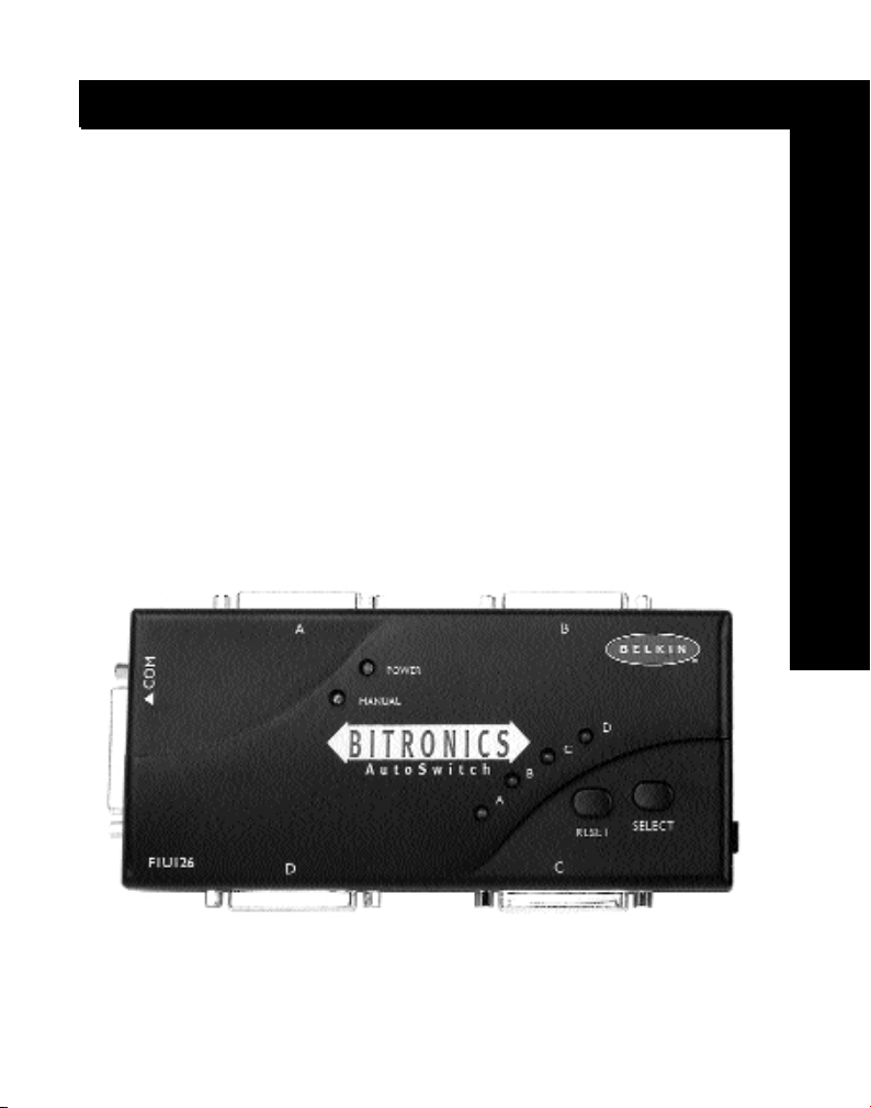
Introduction
Thank you for purchasing the Belkin Components Bitronics AutoSwitch Kit!
Now, you can select between four different parallel devices from your
desktop, or share one device between four computers. Plus, if you are using
Windows
®
95/98 or Windows NT®, you will be able to take advantage of
Bitronics Software, which allows you to print automatically even if you have
more than one printer!
Features
• Allows four computers to share one parallel device or have one computer
select between any four parallel devices
• Virtual Port printer driver software allows fully automatic printer selection
through Windows
• File transfer feature between two PCs compatible with Windows®Direct
Cable Connection, LapLink
• Includes 1.8m IEEE 1284-compliant cable
• Adjustable timeout
Package Contents:
Bitronics AutoSwitch 4-port F1U126
IEEE 1284-compliant cables F2A047-06
Windows
Windows
User manual P73121
®
95/98 and Windows NT
®
and DOS Interlink
®
95/98/NT/DOS software P72735
®
3.x software P72736
®
™
En
Other Parts Needed (if necessary)
• IEEE 1284 printer cable, Belkin Part# F2A046-XX. You will need this
cable to connect a printer to the AutoSwitch. Your current printer
cables may work, but IEEE-compliant cables are recommended.
• IEEE 1284 device cable, Belkin Part# F2A046-XX. You will need this
cable to connect a computer to the AutoSwitch.
Note: "XX" is the length in feet.
1
Page 7

Technical Specifications
Compatible Standards:
IEEE 1284 Parallel Port Communication Standard
Electrical:
Input Voltage: 9VDC
Max Input Current: 600mA
Max Power Consumption: 5.4W
Max Heat Dissipation: 0.31 BTU/min
Environmental:
Storage Temperature: -10ºC to 50ºC
Working Temperature: 0ºC to 40ºC
Relative Humidity: 0 to 95%, Non-condensing
Unit Dimensions:
Width: 18.42cm
Height: 10.8cm
Depth: 2.54cm
Weight: 222g
2
Page 8
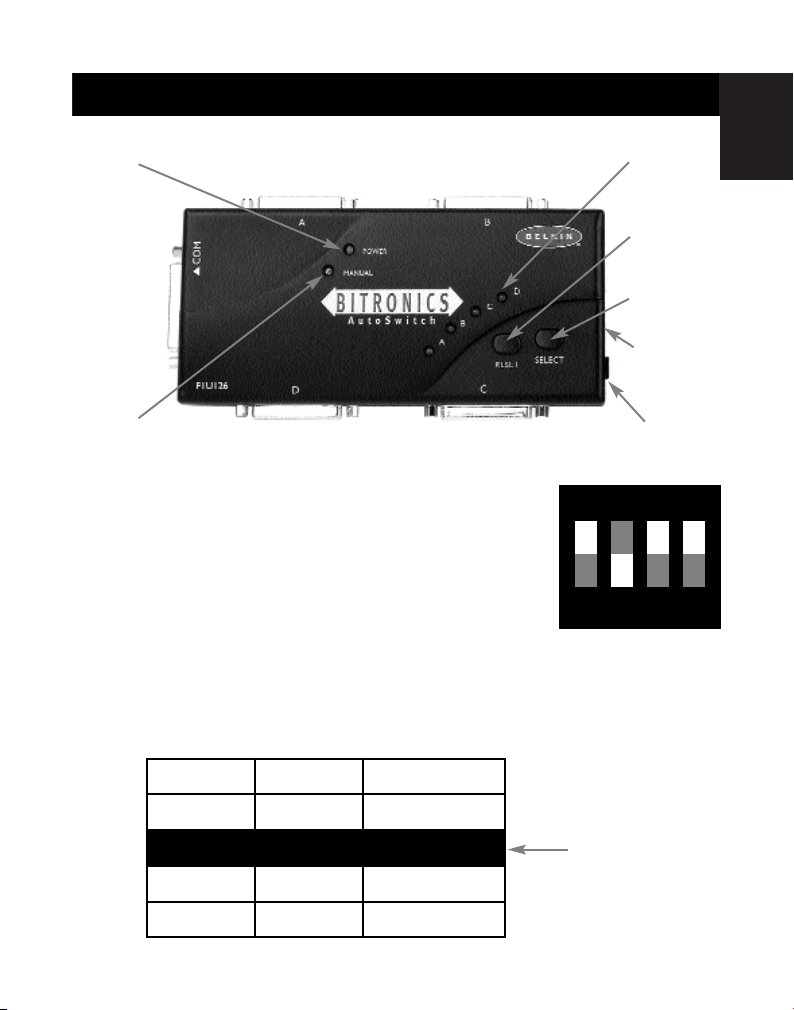
External Power LED
Product Detail
En
Port activity LEDs
Port A Connector
COMMON
Connector
Manual Switching
LED
Port C Connector
DIP switch settings (located on the side of
the switch):
Port B Connector
Port D Connector
RESET
button
SELECT
button
DIP switches
(side)
DC power
jack (side)
ON DIP
SW1: Mode Switch
OFF 4 PCs share 1 device
ON 1 PC selects between 4 devices
ON is DOWN. SW4 is not used.
1234
SW2 and SW3: TimeOut Setting
TimeOut is the amount of time the switch remains locked on a PC port after
data transfer. Use a longer TimeOut when connecting to scanners, mass
storage devices and for large print jobs.
SW2
SW3 TimeOut
ON ON 5 seconds
ON OFF 10 seconds
OFF ON 20 seconds
OFF OFF 40 seconds
3
Recommended
Page 9
Hardware Installation
Make sure all computers, devices, printers and other components are
powered off.
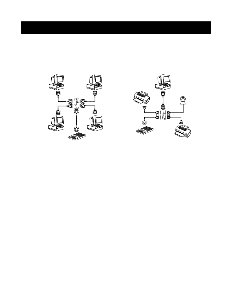
First, you must determine your setup mode:
Four PCs sharing one device One PC using four devices
This is "4 to 1" mode. This is "1 to 4" mode.
You must then set DIP switch #1 according to your mode. Refer to the
previous page for more info.
• For “4 to 1” mode, DIP switch #1 is set to OFF
• For “1 to 4” mode, DIP switch #1 is set to ON
Set DIP switches 2 and 3 to your preference. See previous page.
Next, connect the computer(s), the device(s) and the Bitronics AutoSwitch
together using the proper cables. From a computer to the AutoSwitch, use an
IEEE DB25 M/M cable, such as the one included in the package. For
connecting a printer to the AutoSwitch, use an IEEE printer cable, such as
Belkin Part# F2A046-XX, where XX is the length in feet.
4
Page 10

Setting up your Parallel Port – ECP/EPP Mode
Make sure that the printer port on your computer is set to ECP mode. To do
this, you must go into your computer’s BIOS or CMOS setup. Instructions on
how to do this differ from one computer to the next. Please consult your
computer manufacturer’s manual, tech support, or website for
information regarding how to do this. Please do not call Belkin Tech
Support regarding this because each computer’s BIOS setup routine is
different. Refer to the Appendices at the end of this manual for
information on several models of computers.
The BIOS setup routine prompt is displayed a few seconds after you turn on
your computer and hear its first beeps. Again, this varies from PC to PC.
Please consult the Appendices and/or your computer manufacturer’s
manual or their tech support for information on how to do this properly.
Usually you will see a message that reads Press DEL to enter setup or Press F2
to enter setup. When in the setup program, there maybe a selection for
Integrated Peripherals, or Peripheral Setup. Then, look for Parallel Port Type or
LPT port type. Change that setting to say ECP or ECP/EPP. Save your settings
then exit. When Windows
you for the Windows
®
restarts, it may find new hardware, and it may ask
®
CD. Be prepared to provide this to the computer.
En
5
Page 11

Software Installation
There are two driver disks included with the package. Make sure you put in
the correct disk in your computer depending on your operating system.
When the setup program asks you what model switch you have, make sure
you select F1U126.
• For Windows
then click RUN. In the space, enter “a:\BITRONIX.exe”. The setup
program will commence. Follow the on-screen instructions.
• For MS-DOS (disk P72735), enter the following at the command prompt:
copy a:\DOS\swport.com c:\
• For Windows
space, enter “a:\Setup.exe”. The setup program will commence. Follow
the on-screen instructions.
For proper operation, make sure that:
• The Bitronics software is loaded on both computers. Note that it is not
necessary that both computers be of the same operating system. Just
make sure that the correct Bitronics software is installed based on the
operating system.
• The software and drivers of the device to be shared (i.e. printer,
scanner, etc…) is also loaded on both computers. This is necessary for
each computer to access and use the shared device properly.
Usage – 4 PCs to 1 device mode
When you have four PCs sharing one device (such as a printer, scanner or Zip
Drive), you do not need to use the software. The AutoSwitch automatically
scans all four computers waiting for a print job or requests access to the
shared device. When a computer needs access, the AutoSwitch automatically
connects the device to that computer. After the computer is done accessing
the device, then the AutoSwitch returns to its normal polling mode.
Sharing one scanner, one Zip
the Bitronics AutoSwitch. And since it is automatic, operating systems such
as Windows
AutoSwitch such as a Zip
the computer.
You will see the LEDs flashing back and forth on all the ports on the Bitronics
AutoSwitch. When it locks onto a port, the LED on that port remains lit.
®
95/98 and Windows NT®(disk P72735), click on START,
®
3.x (disk P72736), click on FILE, then click RUN. In the
®
Drive, or one printer is easy and seamless with
®
95 and higher will automatically detect devices through the
®
Drive, as if it was connected directly to
®
6
Page 12
File Transfer Function
When two PCs are connected to the AutoSwitch, they can exchange files
through any standard file transfer program such as Windows
Connection, Interlink
™
or LapLink®.
®
Direct Cable
En
NOTE: Port A can only file transfer to Port B and Port C to Port D only.
If a pair of computers are in file transfer mode (example: A to
B), computers C and D still have access to the shared device.
See the examples below for the different operating systems:
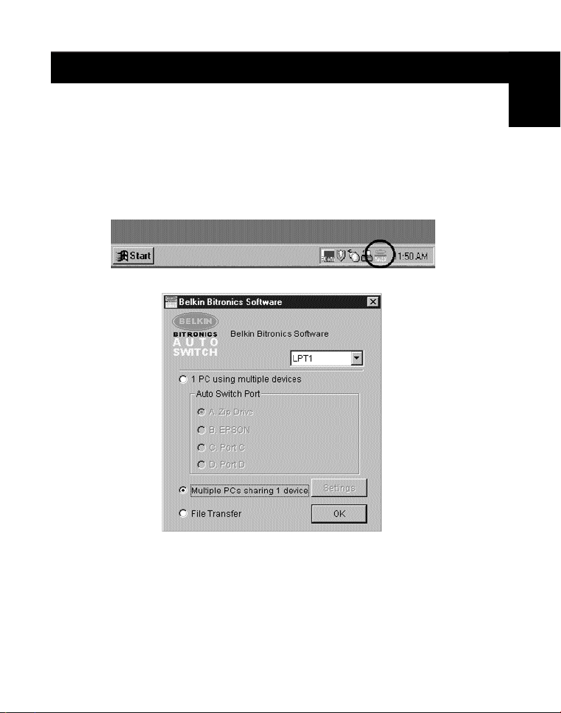
A. Windows®95/98 and Windows NT®:
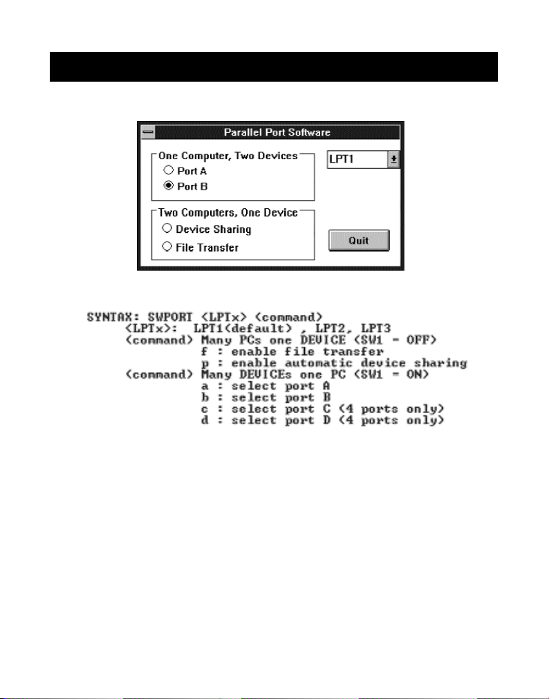
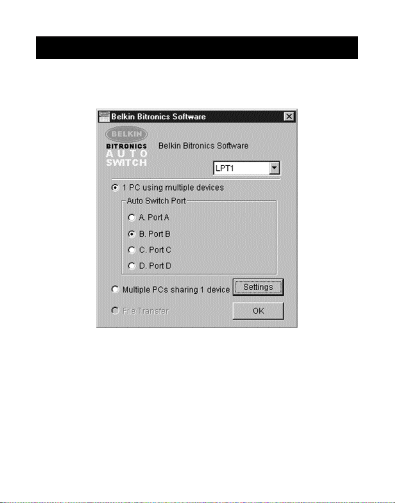
To do this, double-click on the “Bitronics” icon shown in the system tray:
The Bitronics Software will pop-up:
• Click on the pull-down menu on the upper right side if the Bitronics
switch is connected to LPT2 or LPT3. The default and most common
setting is LPT1.
• Click on “Multiple PCs sharing 1 Device”.
• Click on “File Transfer”.
7
Page 13
Windows®95 / 98 and NT
B. Windows®3.x:
• Click on “File Transfer”.
C. MS-DOS:
• At the command prompt, enter “SWPORT f”.
You will see the LED of the port you are connected to on the Bitronics
AutoSwitch turn GREEN. This means that your computer is set to be in File
Transfer mode. However, you also need to set the other computer to File
Transfer mode before you can run your file transfer program. Hence, you must
repeat the above procedure on the other computer. When both LEDs are
green, you are all set to run your file transfer program. The cables and the
AutoSwitch acts like a parallel file transfer cable.
When you are done performing your file transfers, you can resume back to
normal autoswitching mode by pressing the RESET button on the AutoSwitch
or by clicking on “Multiple PCs sharing 1 device” in the Bitronics Software.
®
8
Page 14
Windows®95 / 98 and NT
®
(continued)
Setting up the Bitronics Software for use with 1 PC to 4 Devices
Before anything else, make sure that the drivers of the four devices are
installed on the computer already, and that each device has been tested
and works on its own.
When one computer is switching between four devices, the AutoSwitch
communicates to one device at a time only, and does not know which
device to connect to unless instructed by the user. Through the use of the
Bitronics software, the AutoSwitch receives commands from the computer,
instructing it to switch to a particular port.
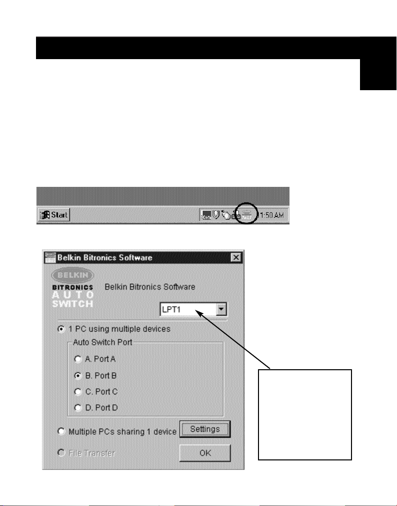
Double-click on the Bitronics icon in the system tray:
The Bitronics Software will pop up:
En
Select the correct
LPT port the
Bitronics switch is
connected to. If you
only have ONE
parallel port (usually
that is the case),
leave this in LPT1.
9
Page 15
Windows®95 / 98 and NT
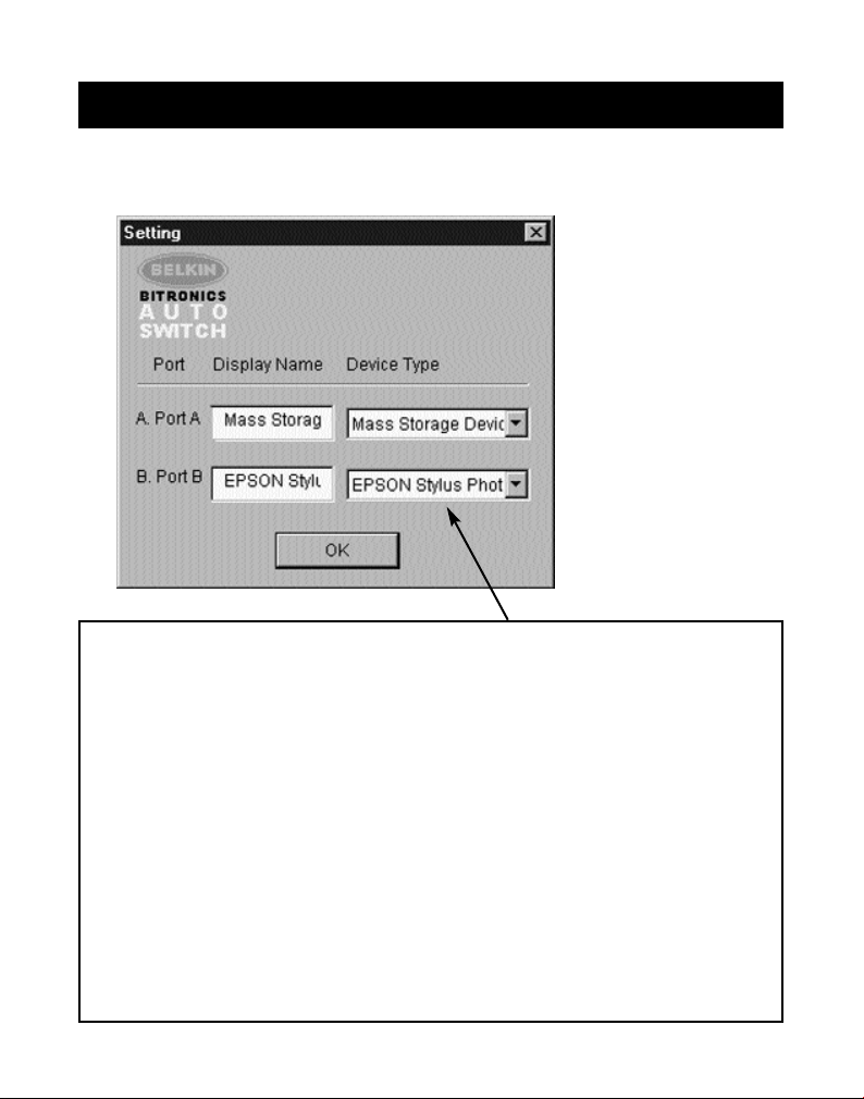
Click on “Settings” button, configure the ports as shown:
“Device Type” gives you a pull-down menu showing the types of printers
installed on your computer and other possible parallel device types as well.
Here, you must select the correct type for the device connected to that port.
• If you are using a device which adds a drive letter to your system (like a
®
Zip
Drive, CD-ROM, LS-120, etc...), use the “Mass Storage Device” setting.
• If you are using a printer, use the printer driver used for that particular
printer on that port of the Bitronics switch. If it does not show up in this
menu, that means the printer drivers have not been installed. (In that
case, reinstall the printer drivers and repeat this step after rebooting
your computer.) If you have more than one printer installed, make sure
that the correct driver is used for the printer connected to that port on
the Bitronics switch.
• For any other parallel device, just use “Scanner”, and change the
“Display Name” accordingly. For example, if you have a parallel tape
drive, use “Scanner” for “Device Type”, then enter “Tape Drive” in
“Display Name”.
®
(continued)
10
Page 16
Windows®95 / 98 and NT
In this example, we have a Zip®Drive on Port A, so we chose “Mass Storage
Device” for Port A. And in Port B, we have the Epson printer installed, so we
chose that driver in the Device Type for Port B.
“Display Name” is a free text field. You can enter
any description here for the attached devices. For
instance, Port A has the Zip
Port B has the InkJet connected. You can rename
these fields to say "My Zip Drive" and "Color
Printer #2".
®
Drive connected and
®
(continued)
En
Click “OK” when finished.
11
Page 17
Windows®95 / 98 and NT
®
(continued)
Change printer port from LPT1 to AutoSwitch port:
(Windows®95/98 only, for Windows NT®go to Page 15)
If one of the four devices being shared is a printer, you must follow the
procedure below to reconfigure the port connected to the printer. If none of
the devices are printers, then you can skip to page 17.
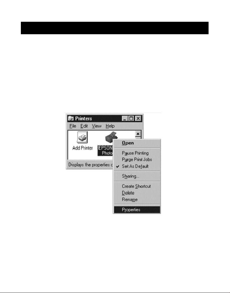
• Click on “Start”, select “Settings”, and double-click on “Printers”.
• Right-click on the printer installed on the Bitronics switch, and click
on “Properties”:
12
Page 18
Windows®95 / 98 and NT
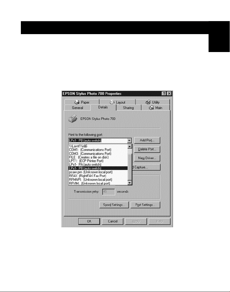
Click on the “Details” tab. In the pull-down menu “Print to the following port:”,
select the correct port this printer is connected to on the Bitronics switch:
• LPx1 – PA (autoswitch) – Select this if the printer is connected to
Port A of the Bitronics switch.
• LPx1 – PB (autoswitch) – Select this if the printer is connected to
Port B of the Bitronics switch. The same occurs for Ports C and D.
®
(continued)
En
In the image above, the printer is connected to Port B of the Bitronics
switch. Therefore, LPx1 – PB (autoswitch) is selected. When finished,
click “OK”.
13
Page 19
Windows®95 / 98 and NT
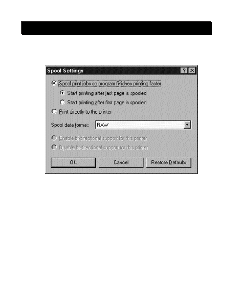
Click on “Spool Settings” and then click on “Start printing after last page
is spooled”.
If NOT grayed out, click on “Disable bi-directional support for this printer”.
Otherwise, ignore.
Click “OK” in the “Spool Settings” window. Click “OK” again in the main
properties window.
Skip to page 17.
®
(continued)
14
Page 20
Windows NT
®
Change printer port from LPT1 to AutoSwitch port
(Windows NT®only):
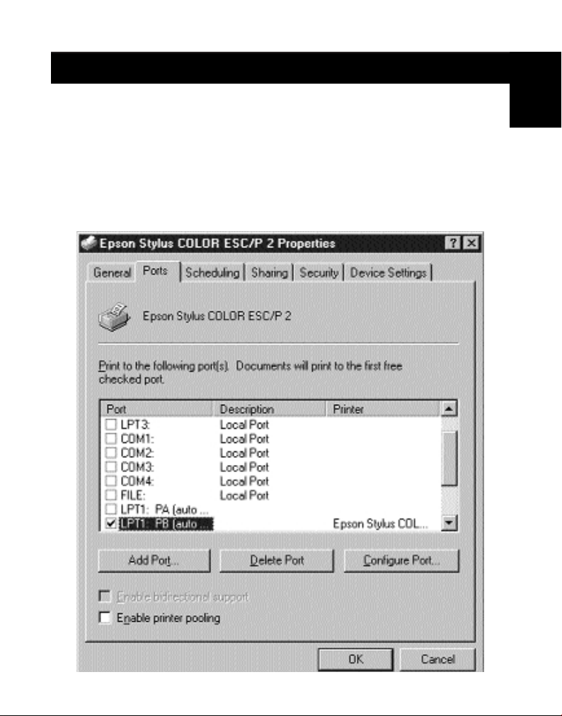
The Printer properties in Windows NT®is slightly different. After installing
the software and restarting the computer, go the printer properties and
select the PORTS tab. To find the correct ports to be used with the
Bitronics switch, you must scroll down the list until the LPT1: PB
(autoswitch) comes up. Put a checkmark on the port that connects to the
printer. In this case, it is Port B on the Bitronics switch:
En
15
Page 21
Windows NT
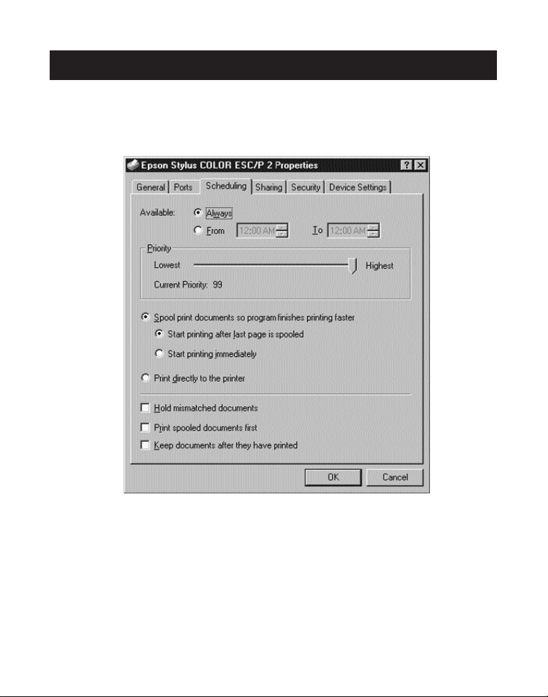
To set the spool settings correctly, click on the “Scheduling” tab. Make sure
“Start printing after last page is spooled” is selected. Also, set “Priority”
to “Highest”:
®
(continued)
Click “OK” when finished.
16
Page 22
Using the Bitronics Software
Example: Four Printers Used by One Computer
The Bitronics Software automatically handles printing chores by directing your
print jobs to the correct port on the Bitronics switch based on the settings you
set in the “Printer Properties” and the “Settings” in the steps shown in the last
6 pages. When you print something in any Windows
Word or Excel), you simply select the printer you wish to print to, and the
Bitronics software handles the switching duties. IT’S FULLY AUTOMATIC!
How does it work?
With the Bitronics Software loaded and the ports properly configured for the
printers as shown previously, when you print in Windows
to the Bitronics software first. There, the Bitronics software adds a command in
the beginning of the print job telling the Bitronics Switch which port to send
the print job to.
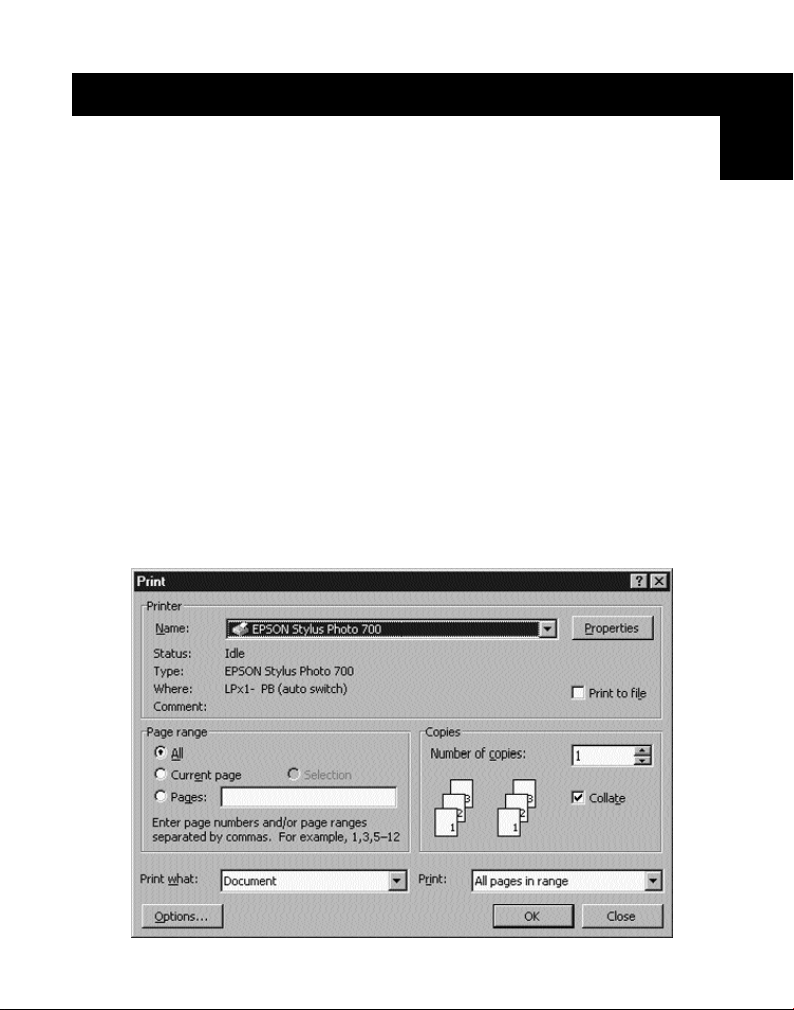
In the example below, the Epson Printer is connected to Port B, as described
in the “Where:” line. When printing, the Bitronics software tells the Bitronics
switch to switch to Port B first, then allows the print job to go through the
switch, out to Port B, and to the Epson printer.
®
application (like MS
®
, the print job goes
En
17
Page 23
Using the Bitronics Software (continued)
Then if you wish to print to the second printer, let’s say a LaserJet™for
example, all you have to do is select that particular printer in the Print dialog
box. Click “OK”, and the print job is automatically sent to the LaserJet
printer on Port A of the Bitronics switch.
All you have to do is pick your printer, and the software does everything else.
But remember, ALL THE SETTINGS MUST BE CORRECT, otherwise you may
print garbage out of the wrong printer!
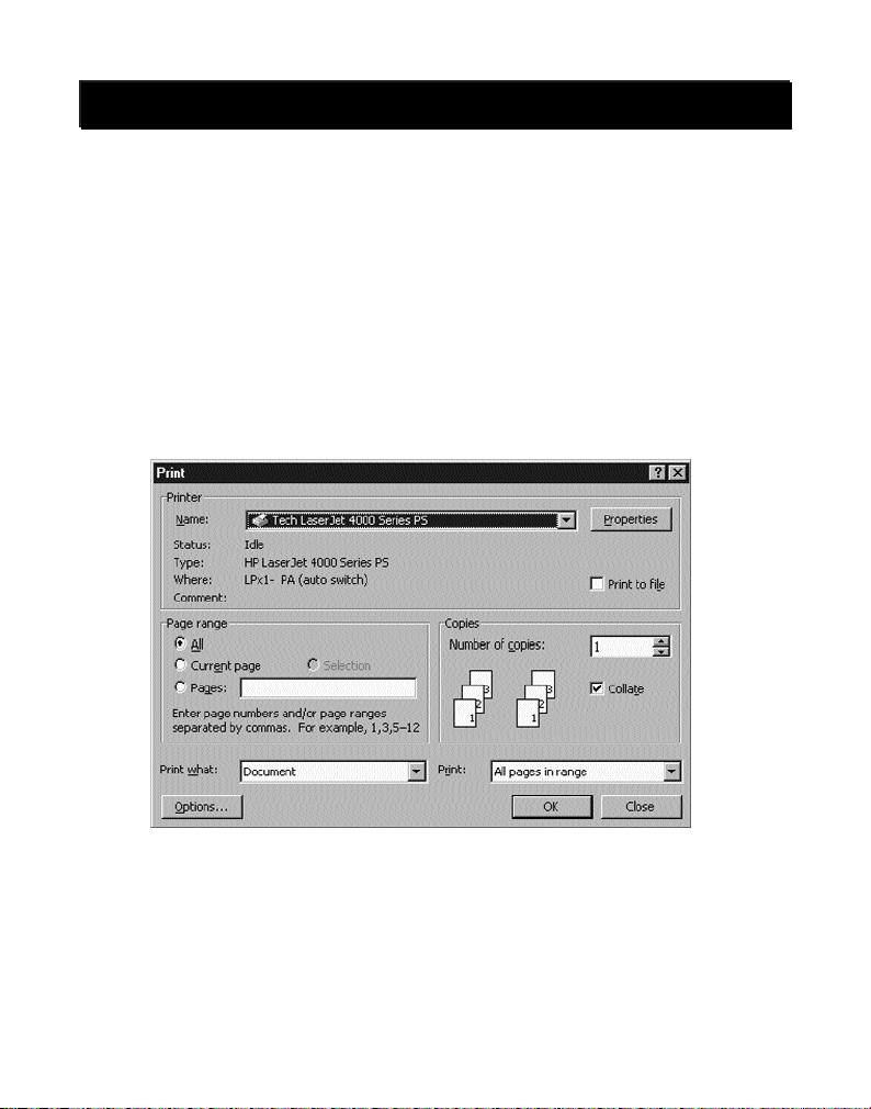
Below, the user has chosen the LaserJet
™
printer. Here, this printer is
connected to Port A of the AutoSwitch. When the print job is sent, the
Bitronics software tells the Bitronics switch to switch to Port A, then lets the
print job go through to the LaserJet
™
.
™
18
Page 24
Using the Bitronics Software (continued)
EXAMPLE: Sharing One Printer and a Zip®Drive (or any other mass
When dealing with a mass storage device (devices that add a drive letter to
your system like E:) such as a Zip
tray must be configured so that the Bitronics switch is defaulted to the Port
attached to the Zip
connected to the Zip
always be connected, and not receive error messages:
1. Make sure that the port that connects to the Zip
storage device)
®
Drive, the Bitronics Software in the system
®
Drive. It is necessary for the switch to always remain
®
Drive so that any time you access that drive, you will
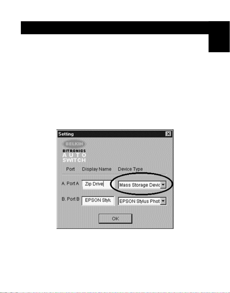
®
“Mass Storage Device” in “Settings”. See above for more info. The
image below shows the Zip
®
Drive is connected to Port A, and that
Drive is set to
the device type is “Mass Storage Device”. Type anything you want
in “Display Name”. Click “OK” when finished.
En
19
Page 25
Using the Bitronics Software (continued)
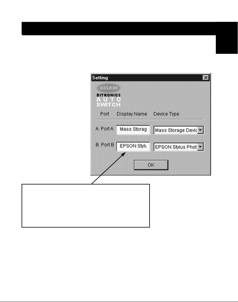
2. Click on the port that has the mass storage device connected. In this
case, it is a Zip
®
Drive on Port A. As you can see, the “Display Name”
entered above appears below as you had entered it. Click “OK”.
Now, the Bitronics switch will always keep your computer connected to the Zip
Drive. That way, anytime you access it, you will not get any strange errors.
Then, when you print to the InkJet printer on Port B (as shown above), the
Bitronics switch will switch to Port B temporarily to send the print job, then
switch back to Port A to keep communication with the Zip
®
Drive.
®
20
Page 26
Using the Bitronics Software (continued)
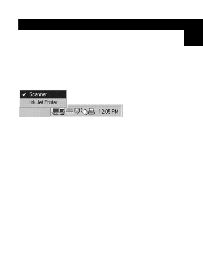
Using any other parallel device (not printers or mass
storage devices) with a printer
When dealing with other parallel port devices, they are set as “Scanners” in
the “Settings” (page 10). Examples of these are scanners, parallel port
cameras, and tape drives. When you need access to this device, simply
single-click on the Bitronics system tray icon, and select the device you wish
to use. A check mark will appear showing which device is connected. For
example, we have a scanner and a printer on the Bitronics switch:
You will be connected to the scanner device indefinitely. But let us say
you wish to print to the InkJet printer, the software will again
automatically switch to the port that has the printer and send the print
job. However, the switch will remain connected to the printer - it will not
change back to the Scanner, unlike the mass storage device mentioned
previously. This means that you have to use this method to switch to the
scanner each time you need to use it.
If no printers are installed
If no printers are installed, the “Settings” type (see page 10) for each device
must be set either for “Mass Storage Device” (if the device adds a drive
letter to your system), or “Scanner” (for all other types of devices).
The Bitronics software may not function properly in some systems if there is
no DEFAULT PRINTER set. To do this, add a printer using the “Add Printer
Wizard” (click “Start”, “Settings”, “Printers”), and just use the “Generic/Text
Only” driver. Remember to use “Local Printer” and “LPT1” when the wizard
asks you. This will then be set as your default printer, so that the Bitronics
software can work properly.
En
21
Page 27

Using the Bitronics Software (continued)
Removing and Adding the Bitronics Switch Icon from the
System Tray
• To remove the icon, simply right click on it, and answer “Yes” to
the prompt.
• To reload the icon back into the system tray, click on “Start”, select
“Programs”, select “Belkin Bitronics Switch”, and select
“AutoSwitch-Multi PCs”.
ADVANCED USER TIP:
If you are using devices with pass-through ports (like Zip®Drives and
scanners), you can connect a printer to the pass-through port and use the
other device port on the Bitronics switch to connect to another device. Just be
sure that the printer driver has its Port set to the correct device port. For
example, if you wish to use 2 printers, 1 Zip
®
Zip
Drive to Port A, the Scanner to Port B, the first printer to the pass-
through of the Zip
®
Drive, and the second printer to the pass-through of the
scanner. In the Bitronics software, set “Port A” to “Mass Storage Device”, and
“Port B” to “Scanner”. Then in the “Printer Properties/details”, set the “Print
to the following Port” to “LPx1- PA (auto switch)” for the first printer, and
“LPx1- PB (auto switch)” for the second printer. In general, only printers can
be connected to pass-through ports.
®
Drive and 1 scanner, connect the
22
Page 28

Appendix
Changing your PC’s parallel port mode to ECP
Changing your computer’s parallel port mode to ECP increases speed and reliability
of data transfers with the Bitronics Switches. Below are the steps on changing the
settings on certain computers. Do this on all the computers connected to the switch.
If your computer is not listed here, please check their website, or call their technical
support. Please do not call Belkin Tech Support regarding this particular issue.
ACER
1. While the computer is booting, follow the directions on the screen: To enter
“Setup”, press CTRL+ALT+ESC.
2. Follow the legend on how to scroll through the options.
3. When you reach the option “Parallel Port Mode”, choose “ECP”.
4. Follow the legend directions to save the setting and exit “Setup”.
AST
1. While the computer is booting, follow the directions on the screen: To enter
“Setup”, press CTRL+ALT+ESC. (If you have a 486 computer, the directions
might have you press CTRL+ALT+DEL).
2. Follow the legend directions on how to scroll through the options.
3. When you reach the “Parallel Port Mode” option, choose the mode with the
highest performance (e.g. “ECP”).
4. Follow the legend directions to save the setting and exit “Setup”.
Generic clone computer
1. Restart the computer and press F1 during the startup.
2. Use an arrow key to select the “Advance” menu item.
3. Use an arrow key to select the parallel port setting and the mode field.
4. Press “ENTER” to get the mode list.
5. Select the mode with the highest performance (e.g. “ECP”) and then
press “ENTER”.
6. Press F10 to save the BIOS (basic input/output system) changes.
7. Press “ENTER” to close the BIOS settings window.
Dell
1. While the computer is booting, follow the directions on the screen: To enter
“Setup”, press DEL. (If you have a 486 computer, the directions might say
press F2.)
2. Press “ALT+P” and choose “Parallel Mode”.
3. There should be a list of modes available. Choose the mode with the highest
performance (e.g. “ECP”).
4. Follow the legend directions to save the setting and exit “Setup”.
Gateway 2000
1. While the computer is booting, follow the directions on the screen: To enter
“Setup”, press F1.
23
En
Page 29

Appendix (continued)
2. Select “Advanced” from the menu bar.
3. Select “Integrated Peripherals”.
4. Following the legend directions, select “ECP” as the parallel port mode.
5. Follow the legend directions to save the setting and exit “Setup”.
Hewlett-Packard
Steps for HP Pavillion PC Models
1. At the HP Blue Screen, press F1 to enter “Setup”.
2. Select “Advanced” from the menu bar.
3. Following the legend directions, select “Peripheral Configuration” and then use
the arrow-down key to move to “Parallel Port Mode”.
4. Select the mode with the highest performance (e.g. “ECP”).
5. Follow the legend directions to save the setting and exit “Setup”.
Steps for HP Vectra PC Series
1. While the computer is booting, follow the directions on the screen: Press F2 to
enter “Setup”. This is displayed at the bottom of the “Hewlett Packard System
Hardware Test” screen.
2. Use the arrow keys to highlight “Parallel Port Mode”.
3. Follow the legend directions on how to change the options.
4. Set the port mode with the highest performance (e.g. “ECP”).
5. Follow the legend directions to save the setting and exit “Setup”.
Steps for HP Vectra 500 PC Series
1. While the computer is booting, follow the directions on the screen: Press F2 to
Enter “Setup”. This is displayed at the bottom of the “Hewlett Packard System
Hardware Test” screen.
2. Use the arrow keys to highlight “Parallel Port Mode”.
3. Follow the legend directions on how to change the options.
4. Set the port mode with the highest performance (e.g. “ECP”).
5. Follow the legend directions to save the setting and exit “Setup”.
Steps for HP OmniBook 5000 and 5500 PCs
1. While the computer is booting, follow the directions on the screen: Press F2 to
Enter “Setup”. This is displayed at the bottom of the “Hewlett Packard System
Hardware Test” screen.
2. Use the arrow keys to highlight “Parallel Port Mode”.
3. Follow the legend directions on how to change the options while selecting the
parallel port mode with the highest performance (e.g. “ECP”).
4. Follow the legend directions to save the setting and exit “Setup”.
5. Add the “Ecpon.com” program to the computer's “Autoexec.bat” file. You can
find this file on the compact disc or on Disk 1 of the disk set.
IBM Aptiva
General Steps
24
Page 30

Appendix (continued)
1. While the computer is booting, follow the directions on the screen: Press F1 to
enter “Setup”.
2. Follow the legend on how to scroll through the “Setup” options until you reach
“Input/Output Ports”.
3. Choose the mode with the highest performance (e.g. “ECP”).
4. Follow the legend directions to save and exit “Setup”.
Steps for IBM Aptiva 2176-C33, IBM BIOS v BSTUS4B
Note: The steps for this computer are not included in the document received in
the box.
1. While the computer is booting, follow the directions on the screen: Press F1 to
enter “Setup”.
2. Follow the legend on how to scroll through the “Setup” options until you reach
“Input/Output Ports”.
3. Select “Parallel Port Mode”.
4. Select “ECP”.
5. Press ESC twice.
6. Press ENTER to save the setting and exit “Setup”.
Micron
General Steps
1. While the computer is booting, follow the directions on the screen: Press F2 to
enter “Setup”.
2. Select “Advanced” from the menu bar.
3. Follow the legend directions to select “Integrated Peripherals”.
4. Use the arrow-down key to select “LPT Mode”.
5. Select the parallel port mode with the highest performance (e.g. “ECP”).
6. Follow the legend directions to save the setting and exit “Setup”.
Steps for the Millennium, Phoenix BIOS v 4.05
Note: The steps for this computer are not included in the document received in
the box.
1. While the computer is booting, follow the directions on the screen: Press F2 to
enter “Setup”.
2. Go to “Connectivity”.
3. Change “Port” from “AT” to “ECP”.
4. Select “PS/2”.
Packard Bell
General Steps
1. While the computer is booting, follow the directions on the screen:
Press F2 to Enter “Setup”. (It might be F1 on some models.)
2. Select “Advanced” from the menu bar.
3. Follow the legend directions to select “Integrated Peripherals” (or “Peripheral
25
En
Page 31

Appendix (continued)
Configuration” on some models).
4. Choose the parallel port mode with the highest performance (e.g. “ECP”).
5. Follow the legend directions to save the setting and exit “Setup”.
Steps for the Force 443 CD, AMBIOS BIOS v 1.00.12.1313oe
1. While the computer is booting, follow the directions on the screen: Press F1 to
Enter “Setup”.
2. Select “Advanced” from the menu bar.
3. Use the down-arrow key to select “Peripheral Config” and then press ENTER.
4. Use the down-arrow key to select “Parallel Port Mode” and then press ENTER.
5. Use the down-arrow key to select “Extended” (originally “Compatible”) and then
press ENTER.
6. Press F10 to save the setting.
Sony
Models PCV-70/90/100/120:
1. Restart your computer.
2. During the first black and white Sony screen, press F3 to enter the boot screen.
3. Press F1 to enter the “BIOS Setup”.
4. Use right-arrow to reach the “Advanced” menu.
5. Scroll down and highlight “Peripheral Configuration” and press ENTER.
6. Scroll down and highlight “Parallel Port Type”. The default setting is
“Compatible”. Press ENTER.
7. Select “ECP” and press ENTER.
8. Press ESC twice to get to the “Exit” screen.
9. Press ENTER twice to “Exit Saving Changes”. The system will restart into Windows®.
Models PCV-130/150:
1. Restart your computer.
2. During the first black and white Sony screen, press F3 to enter the boot screen.
3. Press F1 to enter the “BIOS Setup”.
4. Use right-arrow to reach the “Advanced” menu.
5. Scroll down and highlight “Peripheral Configuration” and press ENTER.
6. Scroll down and highlight “Mode”. The default setting is “ECP”. Press ENTER.
7. Select “ECP”. Press ENTER.
8. Scroll to “Parallel Port” and press ENTER.
9. Select “Enabled” and press ENTER.
10. Press ESC twice to get to the “Exit” screen.
11. Press ENTER twice to “Exit Saving Changes”. The system will restart into Windows
Models PCV-200/210/220/230/240:
1. Restart your computer.
2. During the first black and white Sony screen, press F3 to enter the boot screen.
3. Press F1 to enter the “BIOS Setup”.
4. Use right-arrow to reach the “Advanced” menu.
5. Scroll down and highlight “Peripheral Configuration” and press ENTER.
6. Scroll down and highlight “Mode”. The default setting is “ECP”. Press ENTER.
26
®
.
Page 32

Appendix (continued)
7. Select either “ECP”. Press ENTER.
8. Scroll to “Parallel Port” and press ENTER.
9. Select “Enabled” and press ENTER.
10. Press F10 to save these changes, confirm and exit. The system will restart
into Windows
Sony PCG-705/707/717/719 Notebooks:
1. In Windows
2. Select “Sony Folder”.
3. Select “Sony Utilities”.
4. Select “Sony Notebook Setup”.
5. Select the “Printer/FDD” tab.
6. Make sure “Use as printer connector” is selected and choose the desired port
mode required by the printer. There are three options available on this screen:
1. “Normal” (Output only)
2. “Bi-directional” (default)
3. “ECP” (requires IEEE 1284 printer/parallel cable)
7. Select “ECP” and click “OK” to save results and close the window.
8. Click “Yes” to restart the computer.
Note: Changes made in the “Sony Notebook Utility” are also made in the BIOS.
Sony PCG-729:
1. In Windows
2. Select “Tool Center”.
3. Select “Sony Notebook Setup”.
4. Select the “Printer/FDD” tab.
5. Make sure “Use as printer connector” is selected and choose the desired port
mode required by the printer. There are three options available on this screen:
1. “Normal” (Output only)
2. “Bi-directional” (default)
3. “ECP” (requires IEEE 1284 printer/parallel cable)
6. Select “ECP” and click “OK” to save results and close the window.
7. Click “Yes” to restart the computer.
Note: Changes made in the “Sony Notebook Utility” are also made in the BIOS.
®
.
®
95, open the “Start Menu”.
®
95, open the “Start Menu”.
En
27
Page 33

Information
FCC Statement
DECLARATION OF CONFORMITY WITH FCC RULES FOR ELECTROMAGNETIC
We, Belkin Components, of 501 West Walnut Street, Compton CA 90220, declare under our sole
responsibility that the product:
to which this declaration relates:
Complies with Part 15 of the FCC Rules. Operation is subject to the following two conditions: (1)
this device may not cause harmful interference, and (2) this device must accept any interference
received, including interference that may cause undesired operation.
CE Declaration of Conformity
We, Belkin Components, declare under our sole responsibility that the F1U126-KIT, to which this declaration relates, is
in conformity with Generic Emissions Standard EN50081-1 and with Generic Immunity Standard EN50082-1 1992.
Belkin Components One Year Product Warranty
Belkin Components warrants this product against defects in materials and workmanship for one year. If a defect is
discovered, Belkin will, at its option, repair or replace the product at no charge provided it is returned during the
warranty period, with transportation charges prepaid, to the authorized Belkin dealer from whom you purchased the
product. Proof of purchase may be required.
This warranty does not apply if the product has been damaged by accident, abuse, misuse, or misapplication; if the product
has been modified without the written permission of Belkin; or if any Belkin serial number has been removed or defaced.
THE WARRANTY AND REMEDIES SET FORTH ABOVE ARE EXCLUSIVE IN LIEU OF ALL OTHERS, WHETHER
ORAL OR WRITTEN, EXPRESSED OR IMPLIED. BELKIN SPECIFICALLY DISCLAIMS ANY AND ALL IMPLIED
WARRANTIES, INCLUDING, WITHOUT LIMITATION, WARRANTIES OF MERCHANTABILITY AND FITNESS FOR A
PARTICULAR PURPOSE.
No Belkin dealer, agent, or employee is authorized to make any modification, extension, or addition to this warranty.
BELKIN IS NOT RESPONSIBLE FOR SPECIAL, INCIDENTAL, OR CONSEQUENTIAL DAMAGES RESULTING FROM
ANY BREACH OF WARRANTY, OR UNDER ANY OTHER LEGAL THEORY, INCLUDING BUT NOT LIMITED TO LOST
PROFITS, DOWNTIME, GOODWILL, DAMAGE TO OR REPROGRAMMING, OR REPRODUCING ANY PROGRAM OR
DATA STORED IN OR USED WITH BELKIN PRODUCTS.
COMPATIBILITY
F1U126-KIT
belkin.com
Belkin Components
501 West Walnut Street
Compton • CA • 90220 • USA
Tel: 310.898.1100
Fax: 310.898.1111
© 2000 Belkin Components. All rights reserved. All trade names are registered trademarks of respective manufacturers listed.
Belkin Components, Ltd.
Unit 13 • Gatelodge Close • Round Spinney
Northampton • Northants • NN3 8RX • UK
Tel: +44 (0) 1604678300
Fax: +44 (0) 1604678330
Belkin Components B.V.
Diamantlaan 8 • 2132 WV
Hoofddorp • The Netherlands
Tel: +31 (0) 235698765
Fax: +31 (0) 235612694
Page 34

Introduction
Nous vous remercions d’avoir choisi le kit de l’autocommutateur Bitronics de
Belkin Components ! Vous pouvez désormais choisir entre quatre périphériques
parallèles différents à partir de votre ordinateur de bureau ou partager un
périphérique entre quatre ordinateurs. De plus, si vous travaillez sous Windows
®
95/98 ou Windows NT®, vous pourrez profiter pleinement du logiciel Bitronics
qui vous permet d’imprimer automatiquement même si vous avez plus
d’une imprimante !
Caractéristiques
• Permet à quatre ordinateurs de partager un périphérique parallèle ou à
un ordinateur de choisir entre quatre périphériques parallèles
• Le logiciel de pilote d’imprimante Virtual Port (Port Virtuel) vous permet
de sélectionner automatiquement l’imprimante sous Windows
®
et NT
• Transfert de fichier entre deux PC compatibles avec la Connexion Directe
par câble de Windows
®
, LapLink®et DOS Interlink
™
• Comprend un câble compatible IEEE 1284 d’1,80 m
• Délai d’attente réglable
Contenu de l’emballage :
Autocommutateur Bitronics 4 ports F1U126f
Câbles compatibles IEEE 1284, F2A047f06
Logiciel Windows
Logiciel Windows
Guide de l’utilisateur P73121
®
95/98/NT/DOS P72735
®
3.x P72736
®
95/98
Fr
Autres pièces nécessaires (le cas échéant)
• Câble d’imprimante IEEE 1284, pièce Belkin n° F2A046fXX. Vous aurez
besoin de ce câble pour raccorder une imprimante à l’autocommutateur.
Les câbles actuels de votre imprimante fonctionneront peut-être mais nous
vous conseillons d’utiliser des câbles compatibles IEEE.
• Câble de périphérique IEEE 1284, pièce Belkin n° F2A046fXX. Vous aurez
besoin de ce câble pour raccorder un ordinateur à l’autocommutateur.
REMARQUE : « XX » indique la longueur du câble en pieds
29
Page 35

Spécifications techniques
Normes compatibles
Norme de communication port parallèle IEEE 1284-1994
Électrique :
Tension électrique à l’entrée : 9VDC
Courant maximum à l’entrée : 600mA
Consommation maximale de courant : 5.4W
Dissipation maximale de chaleur : 0.31 BTU/min
Environmental :
Température de stockage : de –10°C à 50°C
Température de travail : de 0°C à 40°C
Humidité relative : de 0 à 95%, pas de condensation
Dimensions de l’unité :
Largeur : 18,42 cm
Hauteur : 10,8 cm
Profondeur : 2,54 cm
Poids : 222 g
30
Page 36

Détails relatifs au produit
DEL d’alimentation externe
Connecteur du port A
Connecteur
COMMUN
DEL de
commutation
manuelle
Connecteur
du port C
Connecteur du port B
Connecteur du port D
DEL indiquant l’activité du port
Bouton de
remise à zéro
(RESET)
Bouton de
sélection
(SELECT)
Interrupteurs
DIP (côté)
Prise cc
(côté)
Paramètres des interrupteurs DIP
(situés sur le côté du commutateur) :
ON DIP
SW1 : Interrupteur du mode
OFF 2 PC partagent 1 périphérique
ON 1 PC choisit entre 2 périphériques
ON : en haut. SW4 n’est pas utilisé
1234
SW2 and SW3 : Fixation du délai
Le délai (TimeOut) correspond au laps de temps durant lequel le commutateur
reste bloqué sur un port de PC après le transfert de données. Optez pour un délai
plus long lorsque vous raccordez des scanners et des unités de stockage à grande
capacité ou pour des impressions volumineuses.
Fr
SW2
SW3 Délai
ON ON 5 secondes
ON OFF 10 secondes
OFF ON 20 secondes
OFF OFF 40 secondes
31
Recommandé
Page 37

Installation du matériel
Vérifiez que tous les ordinateurs, périphériques, imprimantes et autres
appareils sont hors tension.
Vous devez d’abord déterminer votre mode d’installation.
Quatre PC partageant un périphérique Un PC utilisant quatre périphériques
Il s’agit du mode « 4-1 » Il s’agit du mode « 1-4 »
Vous devez ensuite positionner l’interrupteur DIP n°1 en fonction du mode retenu.
Pour de plus amples informations, veuillez vous référer à la page précédente.
• Pour le mode
• Pour le mode « 1-4 », l’interrupteur DIP n°1 est sur ON
Positionnez les interrupteurs DIP 2 et 3 comme vous l’entendez.
Cf. page précédente.
Raccordez ensuite le(s) ordinateur(s), le(s) périphérique(s) et l’autocommutateur
Bitronics Autoswitch en utilisant les câbles appropriés. D’un ordinateur à
l’autocommutateur, utilisez un câble DB25 mâle/mâle IEEE tel que celui qui est
inclus dans l’emballage. Pour raccorder une imprimante à l’autocommutateur,
utilisez un câble d’imprimante IEEE tel que le câble Belkin F2A046fXX, où XX
indique la longueur en pieds.
« 4-1 », l’interrupteur DIP n°1 est sur OFF
32
Page 38

Installation de votre port parallèle-Mode ECP/EPP
Vérifiez que le port imprimante de votre ordinateur est positionné sur le
mode ECP. Pour ce faire, vous devez accéder au programme d’initialisation
du système BIOS ou CMOS de votre ordinateur. La marche à suivre dépend
de l’ordinateur. Veuillez consulter le manuel, le support technique ou le site
web du fabricant de votre ordinateur pour savoir comment procéder. Nous
vous remercions de ne pas appeler le support technique de Belkin à ce
sujet car le programme d’initialisation BIOS diffère selon les ordinateurs.
Pour de plus amples informations sur plusieurs modèles d’ordinateurs,
veuillez vous reporter aux annexes figurant à la fin du présent manuel.
Quelques secondes après avoir allumé l’ordinateur et entendu les premiers
bips, vous voyez apparaître l’invite du programme d’initialisation BIOS. Une
fois encore, ceci varie d’un PC à l’autre. Veuillez consulter les annexes, le
mode d’emploi ou le support technique du fabricant de votre ordinateur
pour connaître la marche à suivre. Vous voyez généralement apparaître un
message disant « Press DEL to enter Setup » ou « Press F2 to enter Setup ».
Une fois dans le programme Setup, vous verrez peut-être apparaître une
sélection pour « Integrated Peripherals » ou « Peripheral Setup ». Cherchez
ensuite « Parallel Port Type » ou « LPT Port Type ». Modifiez ce paramètre afin
d’avoir ECP ou ECP/EPP. Enregistrez ces paramètres et quittez cet écran. En
redémarrant, il se peut que Windows
demande le CD Windows
®
. Soyez prêt à insérer le CD dans l’ordinateur.
®
détecte un nouveau matériel et vous
Fr
33
Page 39

Installation du logiciel
Cet emballage contient deux disquettes de pilotes. Veillez à insérer dans votre
ordinateur la disquette convenant à votre système d’exploitation. Lorsque le
programme d’installation vous demande quel modèle de commutateur vous
possédez, sélectionnez bien F1U125f.
• Pour Windows
puis sur RUN (Exécuter). Dans la case, tapez « a:\BITRONIX.exe ».
Le programme d’installation se mettra en route. Veuillez suivre les
instructions en ligne.
• Pour MS-DOS (disquette P72735), tapez l’instruction suivante à l’invite :
« copy a:\DOS\swport.com c:\ ».
• Pour Windows
(Exécuter). Dans la case, tapez « a:\"Setup".exe ». Le programme
d’installation se mettra en route. Suivez les instructions apparaissant à l’écran.
Pour un bon fonctionnement, vérifiez que :
• Le logiciel Bitronics est chargé sur les quatre ordinateurs. Veuillez noter que
les quatre ordinateurs ne doivent pas nécessairement avoir le même
système d’exploitation. Vérifiez simplement que le logiciel Bitronics installé
correspond bien au système d’exploitation.
• Le logiciel et les gestionnaires du périphérique à partager
|(c’est-à-dire de l’imprimante, du scanner, etc) sont également chargés
sur les quatre ordinateurs. Il s’agit là d’une étape indispensable pour
que chaque ordinateur puisse accéder au périphérique partagé et
l’utiliser correctement.
Utilisation 4 PC – 1 périphérique
Lorsque quatre PC partagent un périphérique (tel qu’une imprimante, un scanner
ou un lecteur Zip
automatiquement les quatre ordinateurs attendant une impression ou demande à
avoir accès au périphérique partagé. Lorsqu’un ordinateur a besoin de cet accès,
l’autocommutateur raccorde automatiquement le périphérique à cet ordinateur.
Une fois que l’ordinateur n’est plus en contact avec le périphérique,
l’autocommutateur se remet en mode d’interrogation normal.
Avec l’autocommutateur Bitronics, partager un périphérique, un lecteur Zip
imprimante devient un jeu d’enfant. De plus, comme il est automatique, les
systèmes d’exploitation tels que Windows
automatiquement les périphériques par l’intermédiaire de l’autocommutateur,
comme le lecteur Zip
YLes voyants DEL s’allumeront alternativement sur tous les ports de
l’autocommutateur Bitronics. Lorsque le commutateur se bloque sur un port, le
voyant DEL de ce port reste allumé.
®
95/98/NT®(disquette P72735), cliquez sur START (Démarrer),
®
3.x (disquette P72736), cliquez sur FILE (Fichier), puis sur RUN
®
), nul besoin d’utiliser le logiciel. L’autocommutateur scanne
®
95 et supérieur détecteront
®
comme s’il était directement connecté à l’ordinateur.
®
ou une
34
Page 40

Fonction de transfert de fichiers
Lorsque deux PC sont reliés à l’autocommutateur, ils peuvent échanger des
fichiers grâce à n’importe quel programme de transfert de fichiers tel que
Windows
REMARQUE : Le port A ne peut transférer de fichiers qu’au port B et le port C qu’au
Les exemples suivants se réfèrent aux différents système d’exploitation :
A. Windows®95/98/NT®:
®
Direct Cable Connection, Interlink™ou LapLink®.
port D. Si deux ordinateurs sont en mode de transfert de fichiers (par
exemple A et B), les ordinateurs C et D auront toujours accès au
périphérique partagé.
Fr
Dans ce cas, double-cliquez sur l’icône Bitronics :
Le logiciel Bitronics apparaîtra alors :
• Cliquez sur le menu déroulant situé en haut à droite si le commutateur
Bitronics est raccordé à LPT2 ou LPT3. La valeur par défaut et la plus
courante est LPT1.
• Cliquez sur « Multiple PCs sharing 1 Device » (Plusieurs PC partageant
un périphérique).
• Cliquez sur « File Transfer ».
35
Page 41

Windows®95 / 98 and NT
B. Windows®3.x :
• Cliquez sur « File Transfer ».
C. MS-DOS:
• A l’invite, tapez « SWPORT f ».
Le voyant DEL du port auquel vous êtes raccordé (sur l’autocommutateur
Bitronics) deviendra VERT. Ceci signifie que l’ordinateur est prêt à
fonctionner en mode « transfert de fichiers ». Vous devez néanmoins mettre
l’autre ordinateur en mode de transfert de fichiers avant de pouvoir lancer
le programme de transfert de fichiers. Vous devez donc répéter la
procédure ci-dessus sur l’autre ordinateur. Lorsque les deux voyants DEL
sont verts, cela signifie que vous êtes prêt à lancer le programme de
transfert de fichiers. Les câbles et l’autocommutateur font office de câble
de transfert de fichiers parallèle.
Lorsque vous avez terminé vos transferts de fichiers, vous pouvez revenir en
mode d’autocommutation normal en appuyant sur le bouton RESET situé sur
l’autocommutateur ou en cliquant sur « Multiple PCs sharing 1 Device »
(Plusieurs PC partageant 1 périphérique).
®
36
Page 42

Windows®95 / 98 and NT
®
(suite)
Installation du logiciel Bitronics pour utiliser l’autocommutateur
en raccordant 1 PC à 4 périphériques
Vérifiez avant tout que les pilotes des quatre périphériques sont déjà
installés sur l’ordinateur et que chaque périphérique a été testé et
fonctionne indépendamment.
Lorsqu’un ordinateur commute entre quatre périphériques,
l’autocommutateur communique uniquement avec un périphérique à la fois
et ne sait pas à quel périphérique se raccorder si l’utilisateur ne le lui dit
pas. Grâce au logiciel Bitronics, l’autocommutateur reçoit des instructions de
l’ordinateur lui ordonnant de passer sur un port donné.
Double-cliquez sur l’icône Bitronics :
Le logiciel Bitronics apparaîtra :
Fr
37
Sélectionnez le port
LPT auquel est relié
le commutateur
Bitronics. Si vous
n’avez qu’UN SEUL
port parallèle (ce qui
est généralement le
cas), gardez LPT1.
Page 43

Windows®95 / 98 and NT
Cliquez sur le bouton « Settings » et configurez le port comme indiqué ci-dessous :
« Device Type » (type de périphérique) fait apparaître un menu déroulant
précisant les types d’imprimantes installées sur votre ordinateur ainsi que d’autres
types de périphériques parallèles possibles.
Vous devez ici sélectionner le type de périphérique approprié raccordé
à ce port.
• Si vous utilisez un périphérique ajoutant une lettre au système (comme un
lecteur Zip®, un lecteur de CD-ROM, LS-120, etc...), utilisez le paramètre
« Mass Storage Device ».
• Si vous utilisez une imprimante, utilisez le pilote d’imprimante utilisé pour
cette imprimante sur ce port du commutateur Bitronics. S’il n’apparaît pas
dans ce menu, cela signifie que les pilotes de l’imprimante n’ont pas été
installés. (Dans ce cas, réinstallez les pilotes d’imprimantes et suivez à
nouveau les instructions de cette étape après avoir réinitialisé votre
ordinateur). Si vous avez installé plus d’une imprimante, veillez à utiliser
le pilote adapté à l’imprimante connectée à ce port sur le
commutateur Bitronics.
• Pour tout autre périphérique parallèle, il vous suffit d’utiliser « Scanner » et
de modifier en conséquence le « Display Name ». Ainsi, si vous avez un
dérouleur de bande, optez pour « Scanner » dans la case correspondant au
type de périphérique (« Device Type ») et indiquez « Tape Drive »
(dérouleur de bande) dans la case « Display Name ».
®
(suite)
38
Page 44

Windows®95 / 98 and NT
Dans cet exemple, comme nous avons un lecteur Zip®sur le port A, nous
choisissons « Mass Storage Device » pour le port A. L’imprimante Epson
est installée sur le port B et nous avons donc choisi ce pilote dans le type
de périphérique correspondant au port B. Cliquez sur OK lorsque vous
avez terminé.
« Display Name » (Nom d’affichage) est un champ
de texte libre. Vous pouvez décrire ici les
périphériques raccordés. Par exemple, le port A
est relié au lecteur Zip
à jet d’encre. Vous pouvez renommer ces champs
en écrivant « My Zip Drive » (Mon lecteur Zip) ou
« Color Printer #2 » (Imprimante couleur numéro).
®
‚ et le port B à l’imprimante
®
(suite)
Fr
Cliquez sur « OK » lorsque vous avez terminé.
39
Page 45

Windows®95 / 98 and NT
®
(suite)
Changez le port de l’imprimante en remplaçant LPT1 par
AutoSwitch : (uniquement sous Windows®95/98 ; sous Windows
NT®veuillez vous référer à la page 43)
Si l’un des quatre périphériques partagés est une imprimante, vous devez
suivre la procédure qui suit afin de reconfigurer le port raccordé à
l’imprimante. Si aucun des périphériques n’est une imprimante, vous pouvez
passer à la page 45.
• Cliquez sur « Start » (Démarrer), « Settings » (Paramètres), puis
« Printers » (Imprimantes).
• Avec le bouton droit de la souris, cliquez sur l’imprimante installée sur le
commutateur Bitronics et cliquez ensuite sur « Properties » (Propriétés) :
40
Page 46

Windows®95 / 98 and NT
Cliquez sur l’onglet « Details ». Dans le menu déroulant « Print to the following
port : » (Imprimer vers :), sélectionnez le port auquel est reliée cette
imprimante sur le commutateur Bitronics :
• LPx1 – PA (autoswitch) — Sélectionnez cette option si l’imprimante
est reliée au port A du commutateur Bitronics.
• LPx1 – PB (autoswitch) — Sélectionnez cette option si l’imprimante
est reliée au port B du commutateur Bitronics.
®
(suite)
Fr
Sur l’image ci-dessus, l’imprimante est reliée au port B du
commutateur Bitronics. LPx1 – PB (autoswitch) est donc sélectionné.
Lorsque vous avez terminé, cliquez sur « OK ».
41
Page 47

Windows®95 / 98 and NT
Cliquez sur « Spool Settings » (Paramètres du spouler) et sur « Start printing after
last page is spooled » (Commencer l’impression après la dernière page).
Cliquez sur « Disable bi-directional support for this printer » (Désactiver le
support bidirectionnel pour cette imprimante) si cette option N’EST PAS
déjà sélectionnée.
Dans la fenêtre des Paramètres du spouleur, cliquez sur « OK ». Cliquez à
nouveau sur « OK » dans la fenêtre des propriétés.
Passez à la page 45.
®
(suite)
42
Page 48

Windows NT
®
Changez le port de l’imprimante en remplaçant LPT1 par AutoSwitch
(uniquement sous Windows NT®):
Les propriétés de l’imprimante diffèrent légèrement sous WindowsNT®.
Après avoir installé le logiciel et redémarré l’ordinateur, allez aux propriétés
de l’imprimante et sélectionnez l’onglet « Ports ». Pour trouver les ports
appropriés qu’il convient d’utiliser avec le commutateur Bitronics, vous devez
faire défiler la liste jusqu’à ce qu’apparaisse « LPx1: PB (autoswitch) ».
Sélectionnez le port relié à l’imprimante. Dans ce cas, il s’agit du port B sur le
commutateur Bitronics :
Fr
43
Page 49

Windows NT
Pour configurer correctement les paramètres du spouleur, cliquez sur l’onglet
« Scheduling ». Vérifiez que l’option « Start printing after last page is spooled »
(Commencer l’impression après la dernière page) est sélectionnée. Optez pour
la plus haute priorité :
®
(suite)
Cliquez sur « OK » lorsque vous avez terminé.
44
Page 50

Utilisation du logiciel Bitronics
Exemple : Un ordinateur utilise quatre
imprimantes.
Le logiciel Bitronics se charge automatiquement de l’impression en envoyant vos
travaux d’impression au port approprié du commutateur Bitronics, et ce en
fonction des paramètres que vous avez définis dans la fenêtre des propriétés de
l’imprimante et des paramètres expliqués dans les 6 pages précédentes. Lorsque
vous effectuez une impression dans n’importe quelle application Windows
®
(comme MS Word ou Excel), il vous suffit de sélectionner l’imprimante vers
laquelle vous souhaitez lancer l’impression et le logiciel Bitronics s’occupe de la
commutation. C’EST ENTIEREMENT AUTOMATIQUE !
Comment cela fonctionne t-il ?
Une fois que le logiciel Bitronics est chargé et que les ports sont dûment
configurés pour les imprimantes, comme indiqué précédemment, lorsque vous
imprimez sous Windows
Bitronics. Le logiciel Bitronics ajoute alors une instruction au début du travail
d’impression, indiquant au commutateur Bitronics à quel port il doit envoyer le
travail d’impression.
Dans l’exemple ci-dessous, l’imprimante Epson est reliée au port B, comme
indiqué sur la ligne « Where ». Lors de l’impression, le logiciel Bitronics ordonne
au commutateur Bitronics de commuter d’abord sur le port B. Il permet ensuite au
travail d’impression de passer par le commutateur, de sortir du port B et de passer
à l’imprimante Epson.
®
, le travail d’impression est d’abord envoyé au logiciel
Fr
45
Page 51

Utilisation du logiciel Bitronics (suite)
Ensuite, si vous voulez imprimer sur la deuxième imprimante (une imprimante
LaserJet
boîte de dialogue « Print » relative à l’impression. Cliquez sur « OK » et le
travail d’impression est automatiquement envoyé à l’imprimante LaserJet
™
par exemple), il vous suffit de sélectionner cette imprimante dans la
™
sur
le port A du commutateur Bitronics.
Vous n’avez qu’à choisir l’imprimante et le logiciel se charge du reste.
Néanmoins, n’oubliez pas que TOUS LES PARAMETRES DOIVENT ETRE
CORRECTS. Faute de quoi, peut-être imprimerez-vous des données erronées
sur la mauvaise imprimante !
Dans l’exemple ci-dessous, l’utilisateur a sélectionné l’imprimante LaserJet
™
.
Ici, l’imprimante est reliée au port A de l’autocommutateur. Lors de l’envoi du
travail d’impression, le logiciel Bitronics ordonne au commutateur Bitronics de
commuter sur le port A et laisse ensuite le travail d’impression aller à
l’imprimante LaserJet
™
.
46
Page 52

Utilisation du logiciel Bitronics (suite)
EXEMPLE : Partage d’une imprimante et d’un lecteur Zip®(ou de tout
autre unité de stockage à grande capacité)
Lorsqu’il s’agit d’une unité de stockage à grande capacité (périphériques
ajoutant une lettre de lecteur à votre système, E: par exemple) comme un
lecteur Zip
configuré afin que le commutateur Bitronics soit, par défaut, relié au port
raccordé au lecteur Zip
®
Zip
®
, le logiciel Bitronics figurant sur l’écran système doit être
®
. Le commutateur doit rester raccordé au lecteur
pour que vous soyez toujours raccordé et ne receviez pas de messages
d’erreur chaque fois que vous accédez au lecteur :
1. Assurez-vous que le port auquel est relié le lecteur Zip
®
correspond
bien à « Mass Storage Device » dans les paramètres. Pour de plus
amples informations, référez-vous aux étapes précédentes. L’image
ci-dessous montre que le lecteur Zip
®
est connecté au port A et
que le type de périphérique est « Mass Storage Device ». Tapez ce
que vous voulez dans la case « Display Name ». Lorsque vous avez
terminé, cliquez sur « OK ».
Fr
47
Page 53

Utilisation du logiciel Bitronics (suite)
2. Cliquez sur le port auquel est raccordé le « Mass Storage Device ».
Dans ce cas, il s’agit d’un lecteur Zip
®
sur le port A. Comme vous
pouvez le constater, le « Display Name » indiqué plus haut apparaît
au dessous tel que vous l’aviez saisi. Cliquez sur « OK ».
Le commutateur Bitronics fera en sorte que votre ordinateur reste toujours
connecté au lecteur Zip®afin d’éviter toute erreur lorsque vous y accédez.
Ensuite, lorsque vous imprimerez sur l’imprimante à jet d’encre sur le port B
(comme indiqué ci-dessus), le commutateur Bitronics passera temporairement
sur le port B pour envoyer le travail d’impression et reviendra ensuite au port A
pour garder le contact avec le lecteur Zip
®
.
48
Page 54

Utilisation du logiciel Bitronics (suite)
Utilisation de tout autre périphérique parallèle (ni imprimante ni unité de stockage à grande capacité) avec
une imprimante.
Lorsque vous utilisez d’autres périphériques sur port parallèle, ils sont
considérés comme les « Scanners » dans les paramètres (cf. p.11). Il s’agit
par exemple des scanners, des caméras sur port parallèle et des dérouleurs
de bande. Lorsque vous devez accéder à ce périphérique, il vous suffit de
cliquer une fois sur l’icône Bitronics de l’écran système et de sélectionner le
périphérique que vous souhaitez utiliser. La case correspondant au
périphérique raccordé sera cochée. Par exemple, nous avons un scanner et
une imprimante sur le commutateur Bitronics :
Vous serez raccordé indéfiniment au périphérique scanner. Toutefois,
supposons que vous souhaitez imprimer sur l’imprimante à jet d’encre. Le
logiciel passera alors automatiquement au port relié à l’imprimante et enverra
le travail d’impression. Néanmoins, le commutateur restera raccordé à
l’imprimante et ne reviendra pas au scanner, contrairement à l’unité de
stockage à grande capacité mentionnée précédemment. Vous devez donc
utiliser cette méthode pour passer au scanner chaque fois que vous
devez l’utiliser.
Si aucune imprimante n’est installée
Si aucune imprimante n’est installée, le type de paramètres (« Settings ») – cf.
étape 7 – pour chaque périphérique sera soit « Mass Storage Device » (si le
périphérique ajoute une lettre de lecteur à votre système), soit « Scanner » (pour
tous les autres types de périphériques).
Il se peut que le logiciel Bitronics ne fonctionne pas correctement dans certains
systèmes si aucune imprimante par défaut (« Default Printer ») n’est indiquée.
Pour y remédier, ajoutez une imprimante en utilisant l’assistant Ajout
d’imprimantes (cliquez sur « Start » (Démarrer), « Settings » (Paramètres) et
« Printers » (Imprimantes), et utilisez simplement « Generic/Text only »
(Générique/texte seulement). N’oubliez pas d’utiliser l’imprimante locale (« Local
Printer ») et LPT1 lorsque l’assistant vous y invite. Ce sera alors votre imprimante
par défaut et le logiciel Bitronics pourra fonctionner correctement.
49
Fr
Page 55

Utilisation du logiciel Bitronics (suite)
Suppression ou ajout de l’icône du commutateur Bitronics sur
l’écran système.
• Pour supprimer l’icône, il vous suffit de cliquer dessus avec le bouton
droit de la souris et de répondre « OUI » à l’invite.
• Pour réinsérer l’icône sur l’écran système, cliquez sur « Start » (Démarrer),
« Programs » (Programmes), sélectionnez « Belkin Bitronics Switch »
(Commutateur Bitronics de Belkin) et « AutoSwitch-Multi PCs ».
ASTUCE POUR USAGER EXPERIMENTE :
Si vous utilisez des périphériques avec des ports pass-through (comme les
lecteurs Zip
port pass-through et utiliser l’autre port de périphérique sur le
commutateur Bitronics pour vous raccorder à un autre périphérique. Vérifiez
simplement que le port du pilote de l’imprimante est sur le bon port de
périphérique. Par exemple, si vous souhaitez utiliser deux imprimantes, un
lecteur Zip
port B, la première imprimante au port pass-through du lecteur Zip
deuxième imprimante au port pass-through du scanner. Dans le logiciel
Bitronics, mettez le port A sur « Mass Storage Device » et le port B sur
« Scanner ». Dans les Propriétés/Détails de l’imprimante, mettez « Print to
the following Port » (Imprimer vers le port suivant) sur « LPx1-PA (auto
switch) » pour la première imprimante et «LPx1-PB » (auto switch) pour la
deuxième imprimante. En général, seules les imprimantes peuvent être
raccordées aux ports pass-through.
®
ou les scanners), vous pouvez raccorder une imprimante au
®
et un scanner, raccordez le lecteur Zip®au port A, le scanner au
®
, et la
50
Page 56

Annexe
Passer du mode port parallèle au mode ECP
Si vous passez au mode ECP, vous augmentez la vitesse et la fiabilité des transferts de
données avec les commutateurs Bitronics. Vous trouverez ci-dessous la marche à
suivre pour modifier les paramètres sur certains ordinateurs. Procédez de la sorte sur
tous les ordinateurs raccordés au commutateur. Si le nom de votre ordinateur ne
figure pas dans la liste, veuillez consulter le site web ou appeler le support technique
du fabricant de votre ordinateur. Nous vous remercions de ne pas appeler le support
technique de Belkin à ce sujet. Nous vous remercions de ne pas appeler le support
technique de Belkin à ce sujet.
ACER
1. Lors du démarrage de votre ordinateur, suivez les instructions qui s’affichent à
l’écran : « To enter Setup, press CTRL+ALT+ESC » (« Pour accéder à l’écran
d’initialisation, appuyez sur CTRL+ALT+ESC »).
2. Les instructions pour faire défiler les options.
3. Lorsque vous arrivez à l’option « Parallel Port Mode », optez pour ECP.
4. Suivez les instructions pour enregistrer les paramètres et quitter
l’écran d’initialisation.
AST
1. Lors du démarrage de votre ordinateur, suivez les instructions qui s’affichent à
l’écran : « To enter Setup, press CTRL+ALT+ESC » (Pour accéder à l’écran
d’initialisation, appuyez sur CTRL+ALT+ESC »). (Si vous possédez un ordinateur
486, les instructions vous demanderont peut-être d’appuyer sur
CTRL+ALT+DEL).
2. Suivez les instructions pour faire défiler les options.
3. Lorsque vous arrivez à l’option « Parallel Port Mode », optez pour le mode
garantissant la meilleure performance (par exemple ECP)
4. Suivez les instructions pour enregistrer les paramètres et quitter
l’écran d’initialisation.
Ordinateur clone générique
1. Redémarrez l’ordinateur et appuyez sur F1 durant la mise en route
2. Avec une touche flèche, sélectionnez l’option « Advanced ».
3. Avec une touche flèche, sélectionnez le paramètre port parallèle et le champ
relatif au mode.
4. Appuyez sur « Enter » (Entrée) pour afficher la liste des modes.
5. Sélectionnez le mode garantissant la meilleure performance (par exemple ECP)
et appuyez sur « Enter » (Entrée).
6. Appuyez sur F10 pour sauvegarder les modifications BIOS (Basic
Input/Output System).
7. Appuyez sur « Enter » (Entrée) pour fermer la fenêtre « BIOS Settings ».
Dell
1. Lors du démarrage de votre ordinateur, suivez les instructions qui s’affichent à
Fr
51
Page 57

Appendix (continued)
l’écran : « To enter Setup, press DEL. » (Pour accéder à l’écran d’initialisation,
appuyez sur DEL). (Si vous possédez un ordinateur 486, peut-être serez vous
invité à appuyer sur F2).
2. Appuyez sur ALT+P et choisissez « Parallel Mode ».
3. Vous devriez voir apparaître la liste des modes disponibles. Sélectionnez le mode
garantissant la meilleure performance (par exemple ECP).
4. Suivez les instructions pour enregistrer les paramètres et quitter l’écran
d’initialisation.
Gateway 2000
1. Lors du démarrage de votre ordinateur, suivez les instructions qui s’affichent à
l’écran : « To enter Setup, press F1. » (Pour accéder à l’écran d’initialisation,
appuyez sur F1).
2. Dans la barre de menu, sélectionnez « Advanced ».
3. Sélectionnez « Integrated Peripherals. ».
4. En suivant les instructions, sélectionnez le mode port parallèle ECP.
5. Suivez les instructions pour enregistrer les paramètres et quitter
l’écran d’initialisation.
Hewlett-Packard
Instructions pour les modèles HP Pavillion PC
1. Sur l’écran HP Blue Screen, appuyez sur F1 pour accéder à
l’écran (initialisation).
2. Dans la barre de menu, sélectionnez « Advanced ».
3. En suivant les instructions, sélectionnez « Peripheral Configuration » et utilisez la
flèche bas pour passer à « Parallel Port Mode ».
4. Sélectionnez le mode garantissant la meilleure performance (par exemple ECP).
5. Suivez les instructions pour enregistrer les paramètres et quitter
l’écran d’initialisation.
Instructions pour la série PC HP Vectra
1. Lors du démarrage de votre ordinateur, suivez les instructions qui s’affichent à
l’écran : « Press F2 to "Enter" Setup » (Appuyez sur F2 pour accéder à l’écran
d’initialisation). Ceci apparaît au bas de l’écran de test de matériel système
d’Hewlett Packard.
2. Utilisez les touches flèches pour sélectionner « Parallel Port Mode ».
3. Suivez les instructions pour modifier les options.
4. Sélectionnez le mode de port garantissant la meilleure performance (par exemple
ECP).
5. Suivez les instructions pour enregistrer les paramètres et quitter
l’écran d’initialisation.
Instructions pour la série HP Vectra 500 PC
1. Lors du démarrage de votre ordinateur, suivez les instructions qui s’affichent à
52
Page 58

Appendix (continued)
l’écran : « Press F2 to "Enter" Setup. » (Appuyez sur F2 pour accéder à l’écran
d’initialisation). Ceci apparaît au bas de l’écran de test de matériel système
d’Hewlett Packard.
2. Utilisez les touches flèches pour sélectionner « Parallel Port Mode ».
3. Suivez les instructions pour modifier les options.
4. Sélectionnez le mode de port garantissant la meilleure performance (par
exemple ECP).
5. Suivez les instructions pour enregistrer les paramètres et quitter
l’écran d’initialisation.
Instructions pour les PC HP OmniBook 5000 and 5500
1. Lors du démarrage de votre ordinateur, suivez les instructions qui s’affichent à
l’écran : « Press F2 to "Enter" Setup » (Appuyez sur F2 pour accéder à l’écran
d’initialisation). Ceci apparaît au bas de l’écran de test de matériel système
d’Hewlett Packard.
2. Utilisez les touches flèches pour sélectionner « Parallel Port Mode ».
3. Suivez les instructions pour modifier les options tout en sélectionnant le mode
port parallèle garantissant la meilleure performance (par exemple ECP).
4. Suivez les instructions pour enregistrer les paramètres et quitter
l’écran d’initialisation.
5. Ajoutez le programme Ecpon :com, au fichier Autoexec.bat de l’ordinateur.
Vous trouverez ce fichier sur le CD-ROM ou sur la disquette numéro 1.
IBM Aptiva
Instructions générales :
1. Lors du démarrage de votre ordinateur, suivez les instructions qui
s’affichent à l’écran : « Press F1 to enter Setup » (Appuyez sur F1 pour
accéder à l’écran d’initialisation).
2. Suivez les instructions pour faire défiler les options d’installation jusqu’à ce
qu’apparaisse « Input/Output Ports ».
3. Optez pour le mode garantissant la meilleure performance (par exemple ECP).
4. Suivez les instructions pour enregistrer les paramètres et quitter
l’écran d’initialisation.
Instructions pour IBM Aptiva 2176-C33, IBM BIOS v BSTUS4B
REMARQUE : Les instructions correspondant à cet ordinateur ne figurent pas
dans le document reçu dans la boîte.
1. Lors du démarrage de votre ordinateur, suivez les instructions qui s’affichent à
l’écran : « : "Press F1 to enter Setup » (Appuyez sur F1 pour accéder à l’écran
d’initialisation).
2. Suivez les instructions pour faire défiler les options d’installation jusqu’à ce
qu’apparaisse « Input/Output Ports ».
3. Sélectionnez « Parallel Port Mode ».
4. Sélectionnez « ECP ».
Fr
53
Page 59

Appendix (continued)
5. Appuyez deux fois sur ESC (Echap).
6. Appuyez sur « Enter » (Entrée) pour enregistrer les paramètres et quitter
l’écran d’initialisation.
Micron
Instructions générales
1. Lors du démarrage de votre ordinateur, suivez les instructions qui s’affichent à
l’écran : « Press F2 to enter Setup » (Appuyez sur F2 pour accéder à
l’écran d’initialisation).
2. Dans la barre de menu, sélectionnez « Advanced ».
3. Suivez les instructions pour sélectionner « Integrated Peripherals ».
4. Utilisez la touche flèche bas pour sélectionner « LPT Mode ».
5. Sélectionnez le mode port parallèle garantissant la meilleure performance (par
exemple ECP).
6. Suivez les instructions pour enregistrer les paramètres et quitter
l’écran d’initialisation.
Instructions pour Millennium, Phoenix BIOS v 4.05
REMARQUE : Les instructions correspondant à cet ordinateur ne figurent pas dans
1. Lors du démarrage de votre ordinateur, suivez les instructions qui s’affichent à
l’écran : « Press F2 to enter Setup.» (Appuyez sur F2 pour accéder à
l’écran d’initialisation).
2. Allez à « Connectivity ».
3. Remplacez le port « AT » par « ECP ».
4. Sélectionnez « PS/2 ».
Packard Bell
Instructions générales
1. Lors du démarrage de votre ordinateur, suivez les instructions qui s’affichent à
l’écran : « Press F2 to "Enter" Setup » (Appuyez sur F2 pour accéder à l’écran
d’initialisation). Sur certains modèles, il est possible qu’il faille appuyer sur F1.
2. Dans la barre de menu, sélectionnez « Advanced ».
3. Suivez les instructions pour sélectionner « Integrated Peripherals » ou, sur
certains modèles, « Peripheral Configuration »).
4. Choisissez le mode de port parallèle garantissant la meilleure performance (par
exemple ECP).
5. Suivez les instructions pour enregistrer les paramètres et quitter
l’écran d’initialisation.
Instructions pour Force 443 CD, AMBIOS BIOS v 1.00.12.1313oe
1. Lors du démarrage de votre ordinateur, suivez les instructions qui s’affichent à
l’écran : « Press F1 to "Enter" Setup.» (Appuyez sur F1 pour accéder à l’écran
d’initialisation).
le document reçu dans la boîte.
54
Page 60

Appendix (continued)
2. Dans la barre de menu, sélectionnez « Advanced ».
3. Utilisez la touche flèche bas pour sélectionner « Peripheral Config »et appuyez
sur « Enter » (Entrée).
4. Utilisez la touche flèche bas pour sélectionner « Parallel Port Mode » et
appuyez ensuite sur « Enter » (Entrée).
5. Utilisez la touche flèche bas pour sélectionner « Extended » - initialement
« Compatible » - et appuyez ensuite sur « Enter » (Entrée).
6. Appuyez sur F10 pour enregistrer les paramètres.
Sony
Models PCV-70/90/100/120:
Modèles PCV-70/90/100/120 :
1. Redémarrez votre ordinateur.
2. Lorsqu’apparaît le premier écran Sony noir et blanc, appuyez sur F3 pour
accéder à l’écran d’initialisation.
3. Appuyez sur F1 pour accéder à l’écran BIOS.
4. Utilisez la flèche de droite pour parvenir au menu « Advanced ».
5. Faites défiler, sélectionnez « Peripheral Configuration » et appuyez sur
« Enter » (Entrée).
6. Faites défiler et sélectionnez « Parallel Port Type ». La valeur par défaut est «
Compatible ». Appuyez sur « Enter » (Entrée).
7. Sélectionnez « ECP » et appuyez sur « Enter » (Entrée).
8. Appuyez deux fois sur ESC (Echap) pour accéder à l’écran « Exit ».
9. Appuyez deux fois sur « Enter » (Entrée) pour quitter l’écran en enregistrant
les modifications. Le système redémarrera sous Windows®.
Models PCV-130/150:
1. Redémarrez votre ordinateur.
2. Lorsqu’apparaît le premier écran Sony noir et blanc, appuyez sur F3 pour
accéder à l’écran d’initialisation.
3. Appuyez sur F1 pour accéder à l’écran BIOS.
4. Utilisez la flèche de droite pour arriver au menu « Advanced ».
5. Faites défiler et sélectionnez « Peripheral Configuration » et appuyez sur
« Enter » (Entrée).
6. Faites défiler et sélectionnez le Mode. La valeur par défaut est « ECP ».
Appuyez sur « Enter » (Entrée).
7. ECP. Appuyez sur « Enter » (Entrée).
8. Faites défiler jusqu’à « Parallel Port » et appuyez sur « Enter » (Entrée).
9. Sélectionnez « Enabled » et appuyez sur « Enter » (Entrée).
10. Appuyez deux fois sur ESC (Echap) pour accéder à l’écran « Exit ».
11. Appuyez deux fois sur « Enter » (Entrée) pour quitter l’écran en enregistrant
les modifications. Le système redémarrera sous Windows®.
Fr
55
Page 61

Appendix (continued)
Models PCV-200/210/220/230/240:
1. Redémarrez votre ordinateur.
2. Lorsqu’apparaît le premier écran Sony noir et blanc, appuyez sur F3 pour accéder
à l’écran d’initialisation.
3. Appuyez sur F1 pour accéder à l’écran BIOS.
4. Utilisez la flèche de droite pour arriver au menu « Advanced ».
5. Faites défiler, sélectionnez « Peripheral Configuration » et appuyez sur « Enter »
(Entrée).
6. Faites défiler et sélectionnez le Mode. La valeur par défaut est « ECP ». Appuyez
sur « Enter » (Entrée).
7. Sélectionnez un ECP. Appuyez sur « Enter » (Entrée).
8. Faites défiler jusqu’à « Parallel Port » et appuyez sur « Enter » (Entrée).
9. Sélectionnez « Enabled » et appuyez sur « Enter » (Entrée).
10. Appuyez sur F10 pour enregistrer ces modifications, confirmez et quittez. Le
système redémarrera sous Windows®.
Sony PCG-705/707/717/719 Notebooks:
1. Sous Windows®95, ouvrez le menu Démarrer.
2. Sélectionnez « Tool Center ».
3. Sélectionnez « Sony Utilities ».
4. Sélectionnez « Sony Notebook Setup ».
5. Sélectionnez l’onglet « Printer/FDD ».
6. Vérifiez que « Use as printer connector » est sélectionné et choisissez le mode de
port souhaité et requis par l’imprimante. Trois options sont possibles sur
cet écran :
1. « Normal » (Sortie uniquement)
2. « Bi-directional » (valeur par défaut)
3. « ECP » (nécessite un câble imprimante/parallèle IEEE 1284)
7. Sélectionnez « ECP » et cliquez sur OK pour enregistrer les modifications et
fermer la fenêtre.
8. Cliquez sur « Yes » (Oui) pour redémarrer l’ordinateur.
REMARQUE : Les modifications apportées à « Sony Notebook Utility » sont également
Sony PCG-729:
1. Sous Windows®95, ouvrez le menu Démarrer.
2. Sélectionnez « Tool Center »
3. Sélectionnez « Sony Notebook Setup »
4. Sélectionnez l’onglet « Printer/FDD »
5. Vérifiez que « Use as printer connector » est sélectionné et choisissez le mode de
apportées au BIOS.
port souhaité et requis par l’imprimante. Trois options sont possibles sur
cet écran :
56
Page 62

Appendix (continued)
1. « Normal » (Sortie uniquement)
2. « Bi-directional » (valeur par défaut)
3. « ECP » (nécessite un câble imprimante/parallèle IEEE 1284)
6. Sélectionnez « ECP » et cliquez sur OK pour enregistrer les modifications et
fermer la fenêtre.
7. Cliquez sur « Yes » (Oui) pour redémarrer l’ordinateur.
Fr
REMARQUE : Les modifications apportées à « Sony Notebook Utility » sont
également apportées au BIOS.
57
Page 63

Information
Réglementation FCC
DECLARATION DE CONFORMITE AVEC LES REGLES FCC POUR LA COMPATI-
Nous, Belkin Components, sis au 501 West Walnut Street, Compton CA 90220, déclarons sous
notre seule responsabilité que le kit du commutateur Bitronics
auquel se réfère la présente déclaration, est conforme à la partie XV des règles FCC. Le fonctionnement doit remplir les deux conditions suivantes : (1) ce périphérique ne doit pas causer d’interférences nuisibles et (2) ce périphérique doit accepter toute interférence reçue, y compris les
interférences pouvant entraîner un fonctionnement non désiré.
Déclaration de conformité CE
Nous, Belkin Components, déclarons sous notre seule responsabilité que le kit du commutateur Bitronics F1U126fKIT
auquel se réfère la présente déclaration, est conforme à la norme sur les émissions génériques EN50081-1 et à la
norme sur l’immunité générique EN50082-1 1992.
Garantie produit limitée à vie de Belkin Components
Belkin garantit ce produit à vie contre tout défaut de matériau et de fabrication. Si l’appareil s’avère défectueux,
Belkin Components le réparera ou le remplacera gratuitement, à sa convenance, à condition que le produit soit
retourné, port payé, pendant la durée de la garantie, au distributeur Belkin agréé auquel le produit a été acheté. Une
preuve d’achat peut être exigée.
La présente garantie est caduque si le produit a été endommagé par accident, abus, usage impropre ou mauvaise
application, si le produit a été modifié sans autorisation écrite de Belkin, ou si un numéro de série Belkin a été supprimé ou rendu illisible.
LA GARANTIE ET LES VOIES DE RECOURS SUSMENTIONNÉES FONT FOI EXCLUSIVEMENT ET REMPLACENT
TOUTES LES AUTRES, ORALES OU ÉCRITES, EXPLICITES OU IMPLICITES. BELKIN REJETTE EXPRESSÉMENT
TOUTES LES GARANTIES IMPLICITES, Y COMPRIS MAIS SANS RESTRICTION, LES GARANTIES AFFÉRENTES À
LA QUALITÉ LOYALE ET MARCHANDE ET À LA POSSIBILITÉ D’UTILISATION À UNE FIN DONNÉE.
Aucun revendeur, représentant ou employé de Belkin n’est habilité à apporter des modifications ou adjonctions à la
présente garantie, ni à la proroger.
BELKIN N’EST PAS RESPONSABLE DES DOMMAGES SPÉCIAUX, DIRECTS OU INDIRECTS, DÉCOULANT D’UNE
RUPTURE DE GARANTIE, OU EN VERTU DE TOUTE AUTRE THÉORIE JURIDIQUE, Y COMPRIS MAIS SANS
RESTRICTION LES PERTES DE BÉNÉFICES, TEMPS D’ARRÊT, FONDS DE COMMERCE, REPROGRAMMATION
OU REPRODUCTION DE PROGRAMMES OU DE DONNÉES MÉMORISÉS OU UTILISÉS AVEC DES PRODUITS
BELKIN OU DOMMAGES CAUSÉS À CES PROGRAMMES OU À CES DONNÉES.
BILITE ELECTROMAGNETIQUE
F1U126fKIT
belkin.com
Belkin Components
501 West Walnut Street
Compton • CA • 90220 • USA
Tel: 310.898.1100
Fax: 310.898.1111
© 2000 Belkin Components. Tous droits réservés. Toutes les raisons commerciales sont des marques déposées de leurs fabricants respectifs.
Belkin Components, Ltd.
Unit 13 • Gatelodge Close • Round Spinney
Northampton • Northants • NN3 8RX • UK
Tel: +44 (0) 1604678300
Fax: +44 (0) 1604678330
Belkin Components B.V.
Diamantlaan 8 • 2132 WV
Hoofddorp • The Netherlands
Tel: +31 (0) 235698765
Fax: +31 (0) 235612694
Page 64

Einleitung
Vielen Dank für den Kauf des Bitronics AutoSwitch Sets von Belkin
Components! Mit diesem Datenumschalter können Sie von Ihrem Desktop
aus vier verschiedene parallele Geräte ansteuern oder sich ein Gerät mit vier
Computern teilen. Darüber hinaus können Sie unter Windows®95, 98 oder
Windows NT®die zugehörige Bitronics Software verwenden, die
Druckaufträge selbst bei Verwendung mehrerer Drucker automatisch zum
richtigen Drucker weiterleitet.
Leistungsmerkmale
• Zwei Computer können sich ein paralleles Gerät teilen, oder ein
Computer kann zwei verschiedene parallele Geräte verwenden
• Virtual Port-Druckertreibersoftware ermöglicht vollautomatische
Druckerauswahl über Windows®95/98 und NT
• Mit Windows®Direct Cable Connection, LapLink®und DOS Interlink
kompatible File Transfer-Funktion für zwei PCs
• Enthält IEEE1284-konformes Kabel (1,8 m)
• Einstellbares Timeout
Packungsinhalt
Bitronics AutoSwitch 4-Port F1U126g
IEEE-1284-konforme Kabel F2A047g06
Windows
Windows®3.x software P72736
Benutzerhandbuch P73121
®
95/98/NT/DOS-Software P72735
®
™
De
Weitere Komponenten (bei Bedarf)
• IEEE 1284-konformes Druckerkabel (Belkin Artikel-Nr. F2A046gXX). Sie
benötigen dieses Kabel für den Anschluß eines Druckers an den
Autoswitch. Eventuell funktionieren auch Ihre aktuellen Druckerkabel,
doch zur Sicherstellung eines optimalen Betriebsverhaltens wird die
Verwendung IEEE-konformer Kabel empfohlen.
• IEEE 1284-konformes Gerätekabel (Belkin Artikel-Nr. F2A046gXX). Sie
benötigen dieses Kabel für den Anschluß eines Computers an den
Autoswitch.
HINWEIS: „XX" gibt die Kabellänge in Fuß an (1 Fuß = 0,3048 m).
59
Page 65

Technische Daten
Kompatible Standards
IEEE 1284-Kommunikationsstandard für Parallelschnittstellen
Elektrische Daten
Eingangsspannung: 9 VDC
Max. Eingangsstrom: 600 mA
Max. Leistungsaufnahme: 5,4 W
Max. Wärmeableitung: 0,31 BTU/Min.
Umgebungsbedingungen
Lagertemperatur: -10ºC bis 50ºC
Betriebstemperatur: 0ºC bis 40ºC
Relative Luftfeuchtigkeit: 0 bis 95%, nicht-kondensierend
Abmessungen
Breite: 18,42 cm
Höhe: 10,8 cm
Tiefe: 2,54 cm
Gewicht: 222 g
60
Page 66

Produktansicht
Externe Netzanzeige
Anschluß für Port A
Gemeinsamer
Anschluß
(COMMON)
LED für manuelle
Umschaltung
Anschluß für
Port C
Einstellung der DIP-Schalter
(an der Seite des Datenumschalters):
Anschluß für Port B
Anschluß für
Port D
LED für
Geräteaktivität
an Port
RESET-Taste
SELECT-Taste
DIP-Schalter
(Seite)
DC-
Netzanschluß
(Seite)
ON DIP
SW1: Modusumschalter
OFF 2 PCs teilen sich ein Gerät
ON 1 PC wählt zwischen 2 Geräten
EIN (ON) ist OBEN. SW4 wird nicht verwendet.
1234
SW2 und SW3: TimeOut-Einstellung
Die TimeOut-Einstellung gibt vor, wie lange der Datenumschalter nach der
Datenübertragung auf einem PC-Anschluß „eingerastet" bleibt. Für
Verbindungen mit Scannern, Massenspeichergeräten und für große
Druckaufträge sollte ein längerer TimeOut eingestellt werden.
De
SW2
SW3 TimeOut
ON ON 5 Sekunden
ON OFF 10 Sekunden
OFF ON 20 Sekunden
OFF OFF 40 Sekunden
61
Empfohlen
Page 67

Hardware-Installation
Stellen Sie sicher, daß alle Computer, Geräte, Drucker und andere
Komponenten ausgeschaltet sind.
Zuerst müssen Sie feststellen, welcher Konfigurationsmodus in Ihrem Fall zutrifft:
Vier PCs teilen sich ein Gerät Ein PC verwendet vier Geräte
Dies ist eine 4:1-Konfiguration. Dies ist eine 1:4-Konfiguration.
Sie müssen dann DIP-Schalter Nr. 1 gemäß diesem Modus einstellen. Näheres
dazu siehe vorherige Seite.
• In der 4:1-Konfiguration wird DIP-Schalter Nr. 1 auf OFF gesetzt.
• In der 1:4-Konfiguration wird DIP-Schalter Nr. 1 auf ON gesetzt.
Stellen Sie die DIP-Schalter 2 und 3 entsprechend dem gewünschten TimeOut
ein. Näheres dazu siehe vorherige Seite.
Verbinden Sie als nächstes den (die) Computer, das (die) Gerät(e) und den
Bitronics AutoSwitch mit Hilfe der richtigen Kabel. Verwenden Sie für die
Verbindung eines Computers mit dem AutoSwitch z.B. das in der Packung
enthaltene IEEE DB25-Kabel (Stecker auf Stecker). Für den Anschluß eines
Druckers an den AutoSwitch verwenden Sie ein IEEE-Druckerkabel (z.B. Belkin
Artikel-Nr. F2A046gXX, wobei „XX" die Kabellänge in Fuß angibt).
Schalten Sie alle Computer und Geräte ein.
62
Page 68

Konfigurieren der Parallelschnittstelle–
ECP/EPP-Modus
Stellen Sie sicher, daß für den Druckeranschluß Ihres PCs der ECP-Modus
eingestellt ist. Diese Einstellung wird im BIOS oder CMOS Setup Ihres
Computers vorgenommen. Wie Sie in dieses Setup gelangen, ist von
Computer zu Computer unterschiedlich. Bitte sehen Sie im Handbuch zu
Ihrem PC oder auf der Website des Computerherstellers nach, oder
wenden Sie sich an den Kundendienst des Herstellers. Rufen Sie wegen
dieser Frage bitte nicht den Technischen Support von Belkin an, denn die
BIOS Setup Routine sieht bei jedem Computer anders aus. Anleitungen
zu einigen Computertypen finden Sie im Anhang zu diesem Handbuch.
Die Eingabeaufforderung für die BIOS Setup Routine wird wenige Sekunden
nach dem Einschalten des Computers und den ersten Signaltönen angezeigt.
Auch dies ist von Computer zu Computer unterschiedlich. Bitte sehen Sie
im Anhang und/oder im Handbuch zu Ihrem Computer nach, wie die BIOS
Setup Routine aufgerufen wird, oder wenden Sie sich an den Kundendienst
des Computerherstellers. Gewöhnlich erscheint eine Meldung mit
folgendem Inhalt: „Press DEL to enter setup" oder „Press F2 to enter
setup" („Drücken Sie DEL, um das Setup zu öffnen" oder „Drücken Sie F2,
um das Setup zu öffnen"). Das Setup-Programm enthält dann eine Option
„Integrated Peripherals" („Integrierte Peripheriegeräte") oder „Peripheral
Setup" („Setup Peripheriegeräte"). Suchen Sie anschließend die Option
„Parallel Port Type" („Typ Parallelschnittstelle") oder „LPT port type" („Art
des LPT-Anschlusses"). Ändern Sie diese Einstellung in „ECP" oder
„ECP/EPP". Speichern Sie die Einstellungen, und beenden Sie das
Programm. Beim Neustart von Windows
Hardware erkannt, und Sie werden nach der Windows
Sie daher diese CD bereit.
®
wird daraufhin eventuell neue
®
CD gefragt. Halten
De
63
Page 69

Software-Installation
In der Packung befinden sich zwei Treiberdisketten. Stellen Sie sicher, daß Sie
die richtige Diskette für Ihr Betriebssystem in Ihren Computer einlegen. Wenn
das „Setup"-Programm Sie nach dem Modell des Datenumschalters fragt,
wählen Sie „F1U125g".
• Bei Windows
und dann auf AUSFÜHREN. Geben Sie „a:\BITRONIX.exe" in das
Feld ein. Das Setup-Programm wird gestartet. Folgen Sie den
Anleitungen am Bildschirm.
• Bei MS-DOS (Diskette P72735) geben Sie folgendes bei der
Eingabeaufforderung ein: „copy a:\DOS\swport.com c:\"
• Bei Windows
AUSFÜHREN. Geben Sie „a:\Setup.exe" in das Feld ein. Das SetupProgramm wird gestartet. Folgen Sie den Anleitungen am Bildschirm.
Stellen Sie zur Gewährleistung eines einwandfreien Betriebs folgendes sicher:
• Die Bitronics Software ist auf beiden Computern geladen. Es muß nicht
unbedingt auf beiden Computern das gleiche Betriebssystem installiert
sein. Vergewissern Sie sich jedoch, daß die richtige Bitronics-Software
für das Betriebssystem installiert ist.
• Die Software und Treiber des Geräts, das gemeinsam genutzt werden
soll (z.B. Drucker, Scanner usw…) wird ebenfalls auf beiden Computern
geladen. Dies ist notwendig, damit jeder Computer das gemeinsame
Gerät richtig ansprechen und nutzen kann.
Anwendung– 4 PCs teilen sich ein Gerät
Wenn sich vier PCs ein Gerät teilen (z.B. einen Drucker, einen Scanner oder ein
®
-Laufwerk), brauchen Sie die Software nicht zu verwenden. Der AutoSwitch
Zip
scannt automatisch alle vier Computer, die auf einen Druckjob warten oder auf
das gemeinsam genutzte Gerät zugreifen wollen. Wenn ein Computer auf ein
Gerät zugreifen will, stellt der AutoSwitch automatisch eine Verbindung
zwischen dem Gerät und dem Computer her. Danach kehrt der AutoSwitch
zum normalen Abfragemodus zurück.
Mit dem Bitronics AutoSwitch können PCs einen Scanner, ein Zip
oder einen Drucker einfach und ohne manuelle Umstellung gemeinsam
nutzen. Der Automatikmodus des AutoSwitch bewirkt, daß Betriebssysteme
wie Windows
erkennen, als seien sie direkt mit dem Computer verbunden.
Die LEDs leuchten an den Ports des Bitronics AutoSwitch abwechselnd auf.
Wenn der AutoSwitch auf einem Port „einrastet", leuchtet nur noch die LED
für diesen Port.
®
95/98/NT (Diskette P72735) klicken Sie auf „START"
®
3.x (Diskette P72736) klicken Sie auf DATEI und dann auf
®
-Laufwerk
®
95 oder höher Geräte wie z.B. Zip®-Laufwerke automatisch so
64
Page 70

File Transfer-Funktion
Wenn zwei PCs mit dem AutoSwitch verbunden sind, können sie Dateien
über Dateitransferprogramme wie Windows
Interlink
HINWEIS: Port A kann nur Dateien an Port B und Port C nur an Port D übertragen.
™
oder LapLink®austauschen.
Wenn der FileTransfer-Modus zwischen zwei Computern aktiviert ist
(Beispiel: von A nach B), können die Computer C und D nach wie vor auf
das gemeinsam verwendete Gerät zugreifen.
®
Direct Cable Connection,
Im folgenden sind Beispiele für die verschiedenen Betriebssysteme aufgeführt:
A. Windows®95/98/NT:
De
Doppelklicken Sie auf das Bitronics-Symbol auf der Task-Leiste:
Die Bitronics Software wird angezeigt:
• Klicken Sie auf das Pulldown-Menü oben rechts, wenn der Bitronics
AutoSwitch mit LPT2 oder LPT3 verbunden ist. Die vorgegebene und
am häufigsten verwendete Einstellung ist LPT1.
• Klicken Sie auf „Multiple PCs sharing 1 Device".
• Klicken Sie auf „File Transfer".
65
Page 71

Windows®95/98/NT
B. Windows®3.x:
• Klicken Sie auf „File Transfer".
C. MS-DOS:
• Geben Sie bei der Eingabeaufforderung „SWPORT f" ein.
Die LED des entsprechenden Computeranschlusses am Bitronics AutoSwitch
leuchtet daraufhin GRÜN. Diese LED zeigt an, daß der Computer, an dem Sie
arbeiten, für den File Transfer-Modus eingestellt ist. Der andere PC muß
jedoch auch für den File Transfer-Modus eingestellt werden, damit Sie Ihr File
Transfer-Programm ausführen können. Daher müssen Sie muß diese Einstellung
auch am anderen Computer vornehmen. Leuchten beide LEDs grün, sind die
Computer bereit zum Dateitransfer. Die Kabel und der AutoSwitch verhalten
sich wie ein paralleles Dateitransfer-Kabel.
Wenn Sie den Dateitransfer abgeschlossen haben, können Sie wieder zum
normalen AutoSwitch-Modus zurückkehren. Drücken Sie hierzu die Taste
RESET auf dem AutoSwitch, oder klicken Sie auf „Multiple PCs sharing 1
Device" in der Bitronics Software.
66
Page 72

Windows®95/98/NT (Fortsetzung)
Konfigurieren der Bitronics Software für den 1:4 Modus
Vor Installation der Bitronics Software ist sicherzustellen, daß die Treiber
der beiden Geräte bereits auf dem Computer installiert sind und jedes
Gerät ordnungsgemäß arbeitet.
Wenn ein Computer vier Geräte abwechselnd nutzt, kommuniziert der
AutoSwitch immer nur mit jeweils einem Gerät und erhält die Information,
mit welchem Gerät eine Verbindung hergestellt werden soll, durch den
Benutzer. Beim Einsatz der Bitronics Software hingegen erhält der
AutoSwitch Anweisungen vom Computer, der ihm mitteilt, zu welchem
Anschluß umgeschaltet werden soll.
Doppelklicken Sie auf das Bitronics-Symbol auf der Task-Leiste:
Die Bitronics Software wird angezeigt:
De
67
Wählen Sie den LPTPort aus, an dem der
Bitronics AutoSwitch
angeschlossen ist.
Wenn Sie nur EINEN
Parallelport haben
(dies ist der
Normalfall),
übernehmen Sie die
Einstellung LPT1.
Page 73

Windows®95/98/NT (Fortsetzung)
Klicken Sie auf die Schaltfläche „SETTINGS" (Einstellungen), und konfigurieren
Sie die Ports wie nachstehend gezeigt:
Für DEVICE TYPE erscheint ein Pulldown-Menü, in dem die auf Ihrem
Computer installierten Druckertypen und eventuell auch weitere parallele
Geräte aufgeführt sind.
Wählen Sie hier den richtigen Gerätetyp aus, der mit diesem Anschluß
verbunden ist.
• Wenn Sie ein Gerät nutzen, das dem System einen eigenen
Laufwerksbuchstaben hinzufügt (z.B. ein Zip®Laufwerk, CD-ROM, LS-120
usw....), wählen Sie MASS STORAGE DEVICE (Massenspeichergerät).
• Bei Verwendung eines Druckers wählen Sie den Druckertreiber, der für
diesen Drucker am betreffenden Port des Bitronics AutoSwitch genutzt
wird. Ist dieser Druckertreiber nicht in diesem Menü aufgeführt,
bedeutet dies, daß die Druckertreiber nicht installiert wurden. (In diesem
Fall installieren Sie die Druckertreiber erneut, und wiederholen Sie
diesen Schritt nach dem Neustart Ihres Computers.) Wenn mehr als ein
Drucker installiert ist, stellen Sie sicher, daß der richtige Treiber für den
Port verwendet wird, mit dem der Drucker am Bitronics Datenumschalter
verbunden ist.
• Bei anderen parallelen Geräten wählen Sie SCANNER und ändern Sie
DISPLAY NAME entsprechend ab. Für ein paralleles Bandlaufwerk
wählen Sie z.B. SCANNER als DEVICE TYPE (Gerätetyp) , und geben
dann „Tape Drive" als DISPLAY NAME ein.
68
Page 74

Windows®95/98/NT (Fortsetzung)
In diesem Beispiel befindet sich ein Zip®-Laufwerk an Port A (Anschluß A);
daher wird MASS STORAGE DEVICE (Massenspeichergerät) für Port A
ausgewählt. An Port B wurde ein Epson-Drucker installiert; daher wird als
Device Type (Gerätetyp) für Port B der betreffende Treiber ausgewählt.
Klicken Sie auf OK, wenn Sie fertig sind.
DISPLAY NAME ist ein Feld für wahlfreien Text.
Sie können hier eine Beschreibung für die
angeschlossenen Geräte eingeben. Wenn an Port
A ein Zip®Laufwerk und an Port B ein InkJet
Drucker angeschlossen ist, können Sie diese
Felder z.B. in „Mein Zip®-Laufwerk" und
„Farbdrucker Nr. 2" ändern.
De
Klicken Sie auf OK, wenn Sie fertig sind.
69
Page 75

Windows®95/98/NT (Fortsetzung)
Druckeranschluß von LPT1 in AutoSwitch Port ändern
(nur Windows®95/98, für Windows®NT®siehe Seite 74):
Ist eines der vier gemeinsam genutzten Geräte ein Drucker, folgen Sie den
nachstehenden Anweisungen, um den für diesen Drucker eingestellten Port
umzukonfigurieren. Ist keines der Geräte ein Drucker, können Sie diesen
Abschnitt überspringen und mit Seite 76 fortfahren.
• Klicken Sie auf START, EINSTELLUNGEN, DRUCKER.
• Klicken Sie mit der rechten Maustaste auf den Drucker, der am
Bitronics-Datenumschalter angeschlossen ist, und klicken
Sie auf EIGENSCHAFTEN.
70
Page 76

Windows®95/98/NT (Fortsetzung)
Klicken Sie auf die Registerkarte DETAILS. Wählen Sie im Pulldown-Menü
„Anschluß für die Druckerausgabe" den Anschluß, mit dem dieser Drucker am
Bitronics-Datenumschalter verbunden ist:
• LPx1 – PA (auto switch) → Wählen Sie diesen Anschluß aus, wenn der
Drucker an Port A des Bitronics-Datenumschalters installiert ist.
• LPx1 – PB (auto switch) → Wählen Sie diesen Anschluß aus, wenn der
Drucker an Port B des Bitronics-Datenumschalters installiert ist.
De
Im Bild oben ist der Drucker an Port B des Bitronics-Datenumschalters
angeschlossen. Deshalb wird LPx1 – PB (auto switch) ausgewählt.
Klicken Sie auf OK, wenn Sie fertig sind.
71
Page 77

Windows®95/98/NT (Fortsetzung)
Klicken Sie auf „Bidirektionale Unterstützung deaktivieren", falls diese
Option NICHT ausgeblendet ist; andernfalls brauchen Sie diesen Punkt
nicht zu beachten.
Klicken Sie im Fenster „Spool-Einstellungen" auf OK und dann im Fenster
„Eigenschaften" noch einmal auf OK.
Weiter mit Seite 76.
72
Page 78

Windows NT
®
Druckeranschluß von LPT1 in AutoSwitch Port ändern
(nur Windows®NT):
Bei den Druckereigenschaften unter Windows®NT gibt es geringfügige
Unterschiede. Rufen Sie nach Installation der Software und Neustart des
Computers die Druckereigenschaften auf, und klicken Sie auf die
Registerkarte „Anschlüsse" (Ports). Um die Anschlüsse zu finden, die in
Verbindung mit dem Bitronics-Datenumschalter zu verwenden sind,
müssen Sie in der Liste nach unten rollen, bis „LPx1: PB (autoswitch)"
erscheint. Markieren Sie den Druckeranschluß mit einem Häkchen. Im
folgenden Beispiel wird Port B des Bitronics-Datenumschalters verwendet:
De
73
Page 79

Windows NT
Zur Festlegung der Spool-Eigenschaften klicken Sie auf die Registerkarte
„Zeitplanung der Druckaufträge" (SCHEDULING). Stellen Sie sicher, daß
„Drucken beginnen, nachdem letzte Seite gespoolt wurde" ausgewählt ist.
Außerdem muß die höchste Priorität eingestellt sein:
®
(Fortsetzung)
Klicken Sie auf OK, wenn Sie fertig sind.
74
Page 80

Verwendung der Bitronics Software
Beispiel: Gemeinsame Nutzung von zwei Druckern durch
einen Computer
Die Bitronics Software wickelt Druckaufgaben automatisch ab, indem
Druckaufträge an den Port des Bitronics-Datenumschalters geleitet werden,
den Sie unter den Eigenschaften des Druckers und in den Einstellungen in
den Schritten auf den letzten 6 Seiten festgelegt haben. Für den Druck aus
Windows®-Anwendungen wie MS Word oder Excel wählen Sie einfach den
gewünschten Drucker aus. Die Bitronics Software kümmert sich dann um alle
Umschaltaufgaben: Sie arbeitet VOLLAUTOMATISCH.
Funktionsweise
Wenn die Bitronics Software installiert ist und die Anschlüsse
ordnungsgemäß für die Drucker konfiguriert wurden, so geht jeder
Druckauftrag beim Drucken unter Windows®zunächst an die Bitronics
Software. Diese setzt an den Anfang des Druckauftrags einen Befehl, der
dem Bitronics-Datenumschalter mitteilt, auf welchem Anschluß der
Druckauftrag ausgegeben werden soll.
Im Beispiel unten ist der Epson-Drucker an Port B angeschlossen, wie die
Zeile „Ort" zeigt. Beim Drucken weist die Bitronics Software den BitronicsDatenumschalter an, erst auf Port B umzuschalten, und leitet den
Druckauftrag dann durch den Datenumschalter über Port B zum
Epson-Drucker.
De
75
Page 81

Verwendung der Bitronics Software (Fortsetzung)
Wenn Sie anschließend den zweiten Drucker verwenden möchten, z.B. einen
LaserJet
auf OK klicken. Der Druckauftrag wird dann automatisch zum LaserJet
™
, so müssen Sie diesen nur im Dialogfeld DRUCKEN auswählen und
™
Drucker an Port A des Bitronics-Datenumschalters gesendet.
Sie müssen also nur den Drucker auswählen, und die Software erledigt
den Rest. Voraussetzung ist jedoch, daß alle EINSTELLUNGEN korrekt
sind: Andernfalls wird möglicherweise auf dem falschen Drucker
Datenmüll ausgedruckt!
Im Beispiel unten wurde der LaserJet
™
Drucker an Port A des AutoSwitch
ausgewählt. Wird ein Druckauftrag abgeschickt, weist die Bitronics Software
den Bitronics Datenumschalter an, auf Port A umzuschalten, und sendet
dann den Druckauftrag zum LaserJet
™
durch.
76
Page 82

Verwendung der Bitronics Software (Fortsetzung)
BEISPIEL: Gemeinsame Nutzung eines Druckers und eines Zip®-
Laufwerks (oder anderen Massenspeichergeräts)
Massenspeichergeräte sind Laufwerke, die dem System einen
Laufwerkbuchstaben wie „E" hinzufügen. Beim Anschluß von
Massenspeichergeräten wie z.B. einem Zip
Software über die Task-Leiste so konfiguriert werden, daß der BitronicsDatenumschalter standardmäßig auf dem Port steht, an dem das Zip
®
-Laufwerk muß die Bitronics
®
Laufwerk angeschlossen ist. Dies ist wichtig, damit Sie stets auf das Laufwerk
zugreifen können und keine Fehlermeldungen erhalten.
1. Als Device Type (Gerätetyp) für den Port, an dem das Zip
®
-Laufwerk
angeschlossen ist, muß in den Bitronics-Einstellungen MASS
STORAGE DEVICE (Massenspeichergerät) eingestellt sein (siehe
vorherigen Schritt). Das Bild unten zeigt, daß an Port A ein Zip‚Laufwerk angeschlossen ist und daß es sich bei dem Gerät um ein
MASS STORAGE DEVICE handelt. Im Feld Display Name
(Anzuzeigender Name) können Sie eine beliebige Bezeichnung
eingeben. Klicken Sie auf OK, wenn Sie fertig sind.
De
77
Page 83

Verwendung der Bitronics Software (Fortsetzung)
2. Klicken Sie auf den Port, an dem das Massenspeichergerät
angeschlossen ist. In diesem Fall befindet sich ein Zip
®
-Laufwerk an
Port A. Wie Sie sehen, erscheint als Name die oben als „Display
Name" eingegebene Bezeichnung. Klicken Sie auf OK.
Der Bitronics-Datenumschalter hält nun stets die Verbindung zwischen Ihrem
PC und dem Zip
wenn Sie auf das Zip
®
-Laufwerk aufrecht. Auf diese Weise treten keine Fehler auf,
®
-Laufwerk zugreifen. Wenn Sie dann einen Druckauftrag
an den InkJet-Drucker an Port B absenden (wie oben beschrieben), schaltet der
Bitronics-Datenumschalter vorübergehend auf Port B, um den Druckauftrag
weiterzuleiten, und wechselt dann wieder auf Port A, um die Datenübertragung
mit dem Zip
®
-Laufwerk aufrechtzuerhalten.
78
Page 84

Verwendung der Bitronics Software (Fortsetzung)
Verwendung eines anderen parallelen Geräts (weder
Drucker noch Massenspeichergerät) in Verbindung mit
einem Drucker
Andere parallele Geräte werden unter SETTINGS (siehe Seite 11) als
SCANNERS (Scanner) eingestellt (dies können neben Scannern z.B. auch
parallele Kameras oder Bandlaufwerke sein). Wenn Sie auf ein Gerät dieser
Art zugreifen möchten, klicken Sie einmal auf das Bitronics-Symbol auf der
Task-Leiste und wählen dann das gewünschte Gerät aus. Ein Häkchen zeigt
an, zu welchem Gerät die Verbindung steht. Hier ist beispielsweise ein
Scanner und ein Drucker am Bitronics-Datenumschalter angeschlossen.
Nachdem der Scanner ausgewählt wurde, bleibt die Verbindung zum
Scanner bestehen. Wenn Sie auf dem InkJet-Drucker ausdrucken wollen,
wechselt der Datenumschalter automatisch auf den Anschluß, an dem
sich der Drucker befindet, und leitet den Druckauftrag durch.
Anschließend bleibt jedoch die Verbindung zum Drucker bestehen, d.h.
anders als im Falle des Zip
Datenumschalter nicht zurück auf den Scanner. Sie müssen den Scanner
also erneut auswählen, um darauf zuzugreifen.
Betrieb ohne Verwendung von Druckern
Die Bitronics Software arbeitet bei manchen System unter Umständen nicht
ordnungsgemäß, wenn kein STANDARDDRUCKER eingestellt ist. Daher
sollten Sie mit dem Assistenten für die Druckerinstallation einen Drucker
hinzufügen (START ‡ EINSTELLUNGEN ‡ DRUCKER ‡ NEUER DRUCKER),
wobei Sie einfach den Treiber „Allgemein" („Generic/Text Only")
verwenden. Geben Sie außerdem „Lokaler Drucker" und „LPT1" an, wenn
der Assistent Sie danach fragt. Dieser Drucker wird dann als
Standarddrucker eingestellt, so daß die Bitronics Software ordnungsgemäß
arbeiten kann.
®
-Laufwerks oben wechselt der
De
79
Page 85

Verwendung der Bitronics Software
(Fortsetzung)
Bitronics Switch-Symbol von der Task-Leiste entfernen/der TaskLeiste hinzufügen
• Zum Entfernen des Symbols klicken Sie einfach mit der rechten Maustaste
darauf und antworten auf die Eingabeaufforderung YES (JA).
• Zum erneuten Laden des Symbols auf der Task-Leiste klicken Sie auf
START, PROGRAMME, BELKIN BITRONICS SWITCH, „AutoSwitchMulti PCs".
Tip für Profis:
Wenn Sie Geräte mit Anschlüssen für die direkte Datendurchleitung verwenden
(z.B. Zip
anschließen und den zweiten Geräteanschluß des Bitronics-Datenumschalters
für ein anderes Gerät verwenden. Achten Sie aber darauf, daß als Anschluß für
den Druckertreiber der richtige Geräteanschluß eingestellt ist. Beispiel: Wenn
Sie zwei Drucker, ein Zip
schließen Sie das Zip
Drucker an den Durchleitungsport des Zip
an den Durchleitungsport des Scanners an. In der Bitronics Software ist Port A
auf „Mass Storage Device" zu setzen und Port B auf „Scanner". Dann ist unter
Eigenschaften/Details (Drucker) als „Anschluß für die Druckausgabe" für den
ersten Drucker „LPx1- PA (auto switch)" und für den zweiten Drucker „LPx1PB (auto switch)" einzustellen. Im allgemeinen können an die
Durchleitungsports nur Drucker angeschlossen werden.
®
-Laufwerke oder Scanner), so können Sie daran einen Drucker
®
-Laufwerk und einen Scanner nutzen möchten,
®
-Laufwerk an Port A, den Scanner an Port B, den ersten
®
-Laufwerks und den zweiten Drucker
80
Page 86

Anhang
Einstellung des ECP-Modus auf der PCParallelschnittstelle
Durch Änderung des Modus der PC-Parallelschnittstelle auf ECP erhöht sich die
Geschwindigkeit und Zuverlässigkeit von Datenübertragungen über den BitronicsDatenumschalter. Wie diese Einstellung zu ändern ist, wird im folgenden für
verschiedene Computer Schritt für Schritt beschrieben. Die Einstellung ist an allen
Computern vorzunehmen, die mit dem Datenumschalter verbunden sind. Ist Ihr PC
hier nicht aufgeführt, sehen Sie bitte auf der Website des Herstellers nach oder
wenden Sie sich an dessen Technischen Support. Bitte rufen Sie wegen dieser
speziellen Frage nicht den Technischen Support von Belkin an.
ACER
1. Während der Computer hochfährt, erscheint am Bildschirm die
Aufforderung „To enter Setup, press CTRL+ALT+ESC". Drücken Sie die
angegebene Tastenkombination.
2. Folgen Sie den Anleitungen zum Durchblättern der verschiedenen Optionen.
3. Wenn Sie die Option „Parallel Port Mode" erreicht haben, wählen Sie dort
„ECP" aus.
4. Folgen Sie den Anleitungen zur Speicherung der Einstellung, und beenden Sie
das Setup-Programm.
AST
1. Während der Computer hochfährt, erscheint am Bildschirm die
Aufforderung „To enter Setup, press CTRL+ALT+ESC" (bei einem 486Prozessor kann die Tastenkombination auch CTRL+ALT+DEL lauten).
Drücken Sie die angegebene Tastenkombination.
2. Folgen Sie den Anleitungen zum Durchblättern der verschiedenen Optionen.
3. Wenn Sie die Option „Parallel Port Mode" erreicht haben, wählen Sie dort den
leistungsstärksten Modus aus (d.h. ECP).
4. Folgen Sie den Anleitungen zur Speicherung der Einstellung, und beenden Sie
das Setup-Programm.
PC-Klon (NoName-Computer)
1. Starten Sie den Computer neu, und drücken Sie während des Hochlaufens F1.
2. Wählen Sie mit Hilfe einer Pfeiltaste die Menüoption „Advance" aus.
3. Wählen Sie mit Hilfe einer Pfeiltaste „Parallel Port Setting" und das Feld
„Mode" aus.
4. Drücken Sie ENTER (Eingabetaste), um die Liste der verschiedenen
Modi aufzurufen.
5. Wählen Sie den leistungsstärksten Modus (d.h. ECP), und drücken Sie dann
ENTER (Eingabetaste).
6. Drücken Sie F10, um die Änderungen im BIOS (Basic Input/Output System)
zu speichern.
De
81
Page 87

Anhang (Fortsetzung)
7. Drücken Sie ENTER (Eingabetaste), um das Fenster mit den BIOS-Einstellungen
zu schließen.
Dell
1. Während der Computer hochfährt, erscheint am Bildschirm die Aufforderung „To
enter Setup, press DEL" (bei einem 486-Prozessor können Sie auch zum Drücken
von F2 aufgefordert werden). Drücken Sie die angegebene Taste.
2. Drücken Sie ALT+P, und wählen Sie „Parallel Mode" aus.
3. Eine Liste von Modi sollte angezeigt werden. Wählen Sie den leistungsstärksten
Modus aus (d.h. ECP).
4. Folgen Sie den Anleitungen zur Speicherung der Einstellung, und beenden Sie
das Setup-Programm.
Gateway 2000
1. Während der Computer hochfährt, erscheint am Bildschirm die Aufforderung „To
enter Setup, press F1". Drücken Sie die angegebene Taste.
2. Wählen Sie „Advanced" aus der Menüleiste aus.
3. Wählen Sie „Integrated Peripherals" (Integrierte Peripheriegeräte) aus.
4. Folgen Sie den Anleitungen, und wählen Sie „ECP" als Modus für die
Parallelschnittstelle (Parallel Port Mode) aus.
5. Folgen Sie den Anleitungen zur Speicherung der Einstellung, und beenden Sie
das Setup-Programm.
Hewlett-Packard
HP Pavillion PCs
1. Drücken Sie bei Anzeige des HP Blue Screen die Taste F1, um das SetupProgramm zu öffnen.
2. Wählen Sie „Advanced" aus der Menüleiste aus.
3. Folgen Sie den Anleitungen, wählen Sie „Peripheral Configuration" aus, und
wählen Sie dann mit Hilfe der Pfeil-nach-unten-Taste „Parallel Port Mode" aus.
4. Wählen Sie den leistungsstärksten Modus aus (d.h. ECP).
5. Folgen Sie den Anleitungen zur Speicherung der Einstellung, und beenden Sie
das Setup-Programm.
HP Vectra PCs
1. Während der Computer hochfährt, erscheint unten im Bild „Hewlett Packard
System Hardware Test" die Aufforderung „Press F2 to Enter Setup".
Drücken Sie F2.
2. Markieren Sie mit Hilfe der Pfeiltasten „Parallel Port Mode".
3. Folgen Sie den Anleitungen zur Änderung der Optionen.
4. Stellen Sie den leistungsstärksten Modus für den Port ein (d.h. ECP).
5. Folgen Sie den Anleitungen zur Speicherung der Einstellung, und beenden Sie
das Setup-Programm.
82
Page 88

Anhang (Fortsetzung)
HP Vectra 500 PCs
1. Während der Computer hochfährt, erscheint unten im Bild „Hewlett Packard
System Hardware Test" die Aufforderung „Press F2 to Enter Setup".
Drücken Sie F2.
2. Markieren Sie mit Hilfe der Pfeiltasten „Parallel Port Mode".
3. Folgen Sie den Anleitungen zur Änderung der Optionen.
4. Stellen Sie den leistungsstärksten Modus für den Port ein (d.h. ECP).
5. Folgen Sie den Anleitungen zur Speicherung der Einstellung, und beenden Sie
das Setup-Programm.
HP OmniBook 5000 und 5500 PCs
1. Während der Computer hochfährt, erscheint unten im Bild „Hewlett Packard
System Hardware Test" die Aufforderung „Press F2 to Enter Setup".
Drücken Sie F2.
2. Markieren Sie mit Hilfe der Pfeiltasten „Parallel Port Mode".
3. Folgen Sie den Anleitungen zur Änderung der Optionen, und stellen Sie den
leistungsstärksten Modus für den Port ein (d.h. ECP).
4. Folgen Sie den Anleitungen zur Speicherung der Einstellung, und beenden Sie
das Setup-Programm.
5. Fügen Sie der Datei Autoexec.bat auf dem PC das Programm Ecpon.com hinzu.
Sie finden dieses Programm auf der CD-ROM oder auf Disk 1
des Diskettensatzes.
IBM Aptiva
Allgemeine Schritte
1. Während der Computer hochfährt, erscheint am Bildschirm die Aufforderung
„Press F1 to enter Setup". Drücken Sie F1.
2. Folgen Sie den Anleitungen zum Durchblättern der verschiedenen Optionen, bis
Sie „Input/Output Ports" erreichen.
3. Wählen Sie den leistungsstärksten Modus aus (d.h. ECP).
4. Folgen Sie den Anleitungen zur Speicherung der Einstellung, und beenden Sie
das Setup-Programm.
IBM Aptiva 2176-C33, IBM BIOS v BSTUS4B
HINWEIS: Die Schritte für diesen Computer finden sich nicht in dem in der
Schachtel enthaltenen Dokument.
1. Während der Computer hochfährt, erscheint am Bildschirm die Aufforderung
„Press F1 to enter Setup". Drücken Sie F1.
2. Folgen Sie den Anleitungen zum Durchblättern der Setup-Optionen, bis Sie
„Input/Output Ports" erreichen.
3. Wählen Sie „Parallel Port Mode" aus.
4. Wählen Sie „ECP" aus.
5. Drücken Sie zweimal ESC.
6. Drücken Sie ENTER (Eingabetaste), um die Einstellung zu speichern und das
Setup-Programm zu beenden.
83
De
Page 89

Anhang (Fortsetzung)
Micron
Allgemeine Schritte
1. Während der Computer hochfährt, erscheint am Bildschirm die Aufforderung
„Press F2 to enter Setup". Drücken Sie F2.
2. Wählen Sie „Advanced" aus der Menüleiste aus.
3. Wählen Sie gemäß den vorgegebenen Anleitungen „Integrated Peripherals" aus.
4. Markieren Sie mit Hilfe der Pfeil-nach-unten-Taste „LPT Mode".
5. Wählen Sie den leistungsstärksten Parallelport-Modus aus (d.h. ECP).
6. Folgen Sie den Anleitungen zur Speicherung der Einstellung, und beenden Sie
das Setup-Programm.
Millennium, Phoenix BIOS v 4.05
HINWEIS: Die Schritte für diesen Computer finden sich nicht in dem in der Schachtel
1. Während der Computer hochfährt, erscheint am Bildschirm die Aufforderung
2. Gehen Sie zu „Connectivity".
3. Ändern Sie „Port" von „AT" in „ECP".
4. Wählen Sie „PS/2" aus.
Packard Bell
Allgemeine Schritte
1. Während der Computer hochfährt, erscheint am Bildschirm die Aufforderung
2. Wählen Sie „Advanced" aus der Menüleiste aus.
3. Wählen Sie gemäß den vorgegebenen Anleitungen „Integrated Peripherals" aus
4. Wählen Sie den leistungsstärksten Parallelport-Modus aus (d.h. ECP).
5. Folgen Sie den Anleitungen zur Speicherung der Einstellung, und beenden Sie
Force 443 CD, AMBIOS BIOS v 1.00.12.1313oe
1. Während der Computer hochfährt, erscheint am Bildschirm die Aufforderung
2. Wählen Sie „Advanced" aus der Menüleiste aus.
3. Wählen Sie mit der Pfeil-nach-unten-Taste „Peripheral Config" aus, und drücken
4. Wählen Sie mit der Pfeil-nach-unten-Taste „Parallel Port Mode" aus, und drücken
5. Wählen Sie mit der Pfeil-nach-unten-Taste „Extended" aus (ursprünglich
6. Drücken Sie F10, um die Einstellung zu speichern.
enthaltenen Dokument.
„Press F2 to enter Setup". Drücken Sie F2.
„Press F2 to enter Setup" (bei manchen Modellen möglicherweise auch „Press F1
to enter Setup"). Drücken Sie die angegebene Taste.
(oder bei manchen Modellen „Peripheral Configuration").
das Setup-Programm.
„Press F1 to Enter Setup". Drücken Sie F1.
Sie ENTER (Eingabetaste).
Sie ENTER (Eingabetaste).
„Compatible"), und drücken Sie ENTER (Eingabetaste).
84
Page 90

Anhang (Fortsetzung)
Sony
PCV-70/90/100/120:
1. Starten Sie den Computer neu.
2. Drücken Sie auf der ersten schwarzweißen Sony-Bildschirmanzeige F3, um die
Start-Bildschirmanzeige („Boot Screen") aufzurufen.
3. Drücken Sie F1, um das BIOS Setup aufzurufen.
4. Gehen Sie mit der Pfeil-nach-rechts-Taste zum Menü „Advanced".
5. Rollen Sie nach unten, markieren Sie „Peripheral Configuration", und drücken
Sie ENTER (Eingabetaste).
6. Rollen Sie nach unten, und markieren Sie „Parallel Port Type". Die
vorgegebene Einstellung ist „Compatible". Drücken Sie ENTER (Eingabetaste).
7. Wählen Sie „ECP" aus, und drücken Sie ENTER (Eingabetaste).
8. Drücken Sie zweimal ESC, um zur Exit-Anzeige zu gelangen.
9. Drücken Sie zweimal ENTER (Eingabetaste), um die Änderungen zu speichern
und das Programm zu beenden („Exit Saving Changes"). Windows®wird
neu gestartet.
Modelle PCV-130/150:
1. Starten Sie den Computer neu.
2. Drücken Sie auf der ersten schwarzweißen Sony-Bildschirmanzeige F3, um die
Start-Bildschirmanzeige („Boot Screen") aufzurufen.
3. Drücken Sie F1, um das BIOS Setup aufzurufen.
4. Gehen Sie mit der Pfeil-nach-rechts-Taste zum Menü „Advanced".
5. Rollen Sie nach unten, markieren Sie „Peripheral Configuration", und drücken
Sie ENTER (Eingabetaste).
6. Rollen Sie nach unten, und markieren Sie „Mode". Die vorgegebene Einstellung
ist „ECP". Drücken Sie ENTER (Eingabetaste).
7. Wählen Sie „ECP" aus, und drücken Sie ENTER (Eingabetaste).
8. Rollen Sie zu „Parallel Port", und drücken Sie ENTER (Eingabetaste).
9. Wählen Sie „Enabled" aus, und drücken Sie ENTER (Eingabetaste).
10. Drücken Sie zweimal ESC, um zur Exit-Anzeige zu gelangen.
11. Drücken Sie zweimal ENTER (Eingabetaste), um die Änderungen zu
speichern und das Programm zu beenden („Exit Saving Changes"). Windows
wird neu gestartet.
PCV-200/210/220/230/240:
1. Starten Sie den Computer neu.
2. Drücken Sie auf der ersten schwarzweißen Sony-Bildschirmanzeige F3, um die
Start-Bildschirmanzeige („Boot Screen") aufzurufen.
3. Drücken Sie F1, um das BIOS Setup aufzurufen.
4. Gehen Sie mit der Pfeil-nach-rechts-Taste zum Menü „Advanced".
5. Rollen Sie nach unten, markieren Sie „Peripheral Configuration", und drücken
Sie ENTER (Eingabetaste).
De
®
85
Page 91

Anhang (Fortsetzung)
6. Rollen Sie nach unten, und markieren Sie „Mode". Die vorgegebene Einstellung ist
„ECP". Drücken Sie ENTER (Eingabetaste).
7. Wählen Sie „ECP" aus, und drücken Sie ENTER (Eingabetaste).
8. Rollen Sie zu „Parallel Port", und drücken Sie ENTER (Eingabetaste).
9. Wählen Sie „Enabled" aus, und drücken Sie ENTER (Eingabetaste).
10. Drücken Sie F10, um die Änderungen zu speichern, bestätigen Sie, und beenden
Sie das Programm. Windows®wird neu gestartet.
Sony PCG-705/707/717/719 Notebooks:
1. Öffnen Sie unter Windows®95 das Start-Menü.
2. Wählen Sie den Sony-Ordner aus.
3. Wählen Sie „Sony Utilities" aus.
4. Wählen Sie „Sony Notebook Setup" aus.
5. Wählen Sie die Registerkarte „Printer/FDD" aus.
6. Stellen Sie sicher, daß „Use as printer connector" ausgewählt ist, und wählen Sie
den vom Drucker benötigten Anschlußmodus aus. Die Maske bietet Ihnen drei
Möglichkeiten an:
1. „Normal" (Nur senden)
2. „Bi-directional" (Standardwert)
3. „ECP" (erfordert IEEE 1284-Drucker-/Parallel-kabel)
7. Wählen Sie „ECP" aus, klicken Sie auf OK, um die Ergebnisse zu speichern, und
schließen Sie das Fenster.
8. Klicken Sie auf „Yes", um den Computer neu zu starten.
HINWEIS: Änderungen, die Sie in der Sony Notebook Utility vornehmen werden, wer
Sony PCG-729:
1. Öffnen Sie unter Windows®95 das Start-Menü.
2. Wählen Sie „Tool Center" aus.
3. Wählen Sie „Sony Notebook Setup" aus.
4. Wählen Sie die Registerkarte „Printer/FDD" aus.
5. Stellen Sie sicher, daß „Use as printer connector" ausgewählt ist, und wählen Sie
6. Wählen Sie „ECP" aus, klicken Sie auf OK, um die Ergebnisse zu speichern, und
7. Klicken Sie auf „Yes", um den Computer neu zu starten.
HINWEIS: Änderungen, die Sie in der Sony Notebook Utility vornehmen werden, wer
den auch im BIOS übernommen.
den vom Drucker benötigten Anschlußmodus aus. Die Maske bietet Ihnen drei
Möglichkeiten an:
1. „Normal" (Nur senden)
2. „Bi-directional" (Standardwert)
3. „ECP" (erfordert IEEE 1284- Drucker-/Parallelkabel)
schließen Sie das Fenster.
den auch im BIOS übernommen.
86
Page 92

Informationen
FCC-Erklärung
ERKLÄRUNG ZUR EINHALTUNG DER FCC-VORSCHRIFTEN BEZÜGLICH
Wir, Belkin Components, 501 West Walnut Street, USA - Compton CA 90220, erklären hiermit in alleiniger
Verantwortung, daß unser Produkt:
folgende Voraussetzungen erfüllt:
Dieses Gerät entspricht Teil 15 der FCC-Vorschriften. Der Betrieb unterliegt den folgenden Bedingungen: (1) das
Gerät darf keine nachteiligen Störungen verursachen und (2) muß empfangene Störungen ausgleichen können,
auch wenn diese geeignet sind, den Betrieb nachteilig zu beeinflussen.
.
CE-Konformitätserklärung
Wir, Belkin Components, erklären hiermit in alleiniger Verantwortung, daß der Artikel F1U126gKIT, auf den sich diese
Erklärung bezieht, in Einklang mit der Fachgrundnorm Störaussendung EN50081-1 und der Fachgrundnorm
Störfestigkeit EN50082-1 (1992) steht.
Belkin Components Ein Jahr Produktgarantie
Belkin Components gewährleistet hiermit, daß dieses Produkt während eines Zeitraums von einem Jahr keine
Verarbeitungs- und Materialfehler aufweisen wird. Bei Feststellung eines Fehlers wird Belkin das Produkt nach
eigenem Ermessen entweder kostenlos reparieren oder austauschen, sofern es während des Garantiezeitraums an den
autorisierten Belkin-Händler zurückgegeben wurde, bei dem es gekauft wurde. Die Kosten für den Rücktransport zum
Belkin-Händler sind vom Kunden zu tragen. Ein Kaufnachweis kann verlangt werden.
Diese Gewährleistung erstreckt sich nicht auf die Beschädigung des Produkts durch Unfall, mißbräuchliche,
unsachgemäße oder fehlerhafte Verwendung oder Anwendung. Ebenso ist die Gewährleistung unwirksam, wenn das
Produkt ohne schriftliche Genehmigung durch Belkin verändert wurde oder wenn eine Belkin-Seriennummer entfernt
oder unkenntlich gemacht wurde.
DIE VORSTEHENDEN GEWÄHRLEISTUNGEN UND RECHTSBEHELFE SCHLIEßEN ALLE ANDEREN
GEWÄHRLEISTUNGEN UND RECHTSBEHELFE - OB MÜNDLICH ODER SCHRIFTLICH, AUSDRÜCKLICH ODER
KONKLUDENT - AUS UND TRETEN AN DEREN STELLE. BELKIN ÜBERNIMMT INSBESONDERE KEINERLEI
KONKLUDENTE GEWÄHRLEISTUNGEN, U.A. AUCH KEINE GEWÄHRLEISTUNG DER EIGNUNG FÜR EINEN
BESTIMMTEN ZWECK UND DER HANDELSÜBLICHEN QUALITÄT.
Kein Händler, Bevollmächtigter bzw. Vertreter oder Mitarbeiter von Belkin ist befugt, diese Gewährleistungsregelung
in irgendeiner Weise abzuändern oder zu ergänzen.
BELKIN HAFTET NICHT FÜR BESONDERE, DURCH ZUFALL EINGETRETENE ODER FOLGESCHÄDEN AUFGRUND
DER VERLETZUNG EINER GEWÄHRLEISTUNG ODER NACH MAßGABE EINER ANDEREN RECHTSLEHRE (U.A. FÜR
ENTGANGENE GEWINNE, AUSFALLZEITEN, GESCHÄFTS- ODER FIRMENWERTEINBUßEN BZW. DIE
BESCHÄDIGUNG, NEUPROGRAMMIERUNG ODER WIEDERHERSTELLUNG VON PROGRAMMEN ODER DATEN
NACH SPEICHERUNG IN ODER NUTZUNG IN VERBINDUNG MIT
BELKIN-PRODUKTEN).
ELEKTROMAGNETISCHER UND HOCHFREQUENTER STÖRUNGEN
F1U126gKIT
De
belkin.com
Belkin Components
501 West Walnut Street
Compton • CA • 90220 • USA
Tel: 310.898.1100
Fax: 310.898.1111
© 2000 Belkin Components. Alle rechte vorbehalten. Alle markennamen sind eingetragene marken der angegebenen hersteller.
Belkin Components, Ltd.
Unit 13 • Gatelodge Close • Round Spinney
Northampton • Northants • NN3 8RX • UK
Tel: +44 (0) 1604678300
Fax: +44 (0) 1604678330
Belkin Components B.V.
Diamantlaan 8 • 2132 WV
Hoofddorp • The Netherlands
Tel: +31 (0) 235698765
Fax: +31 (0) 235612694
Page 93

Inleiding
Belkin Components dankt u hartelijk voor de aankoop van de Bitronics
AutoSwitch Kit! U kunt nu vanaf uw werkplek kiezen tussen vier
verschillende parallelle apparaten of één apparaat met vier computers
delen. Als gebruiker van Windows
®
95/98 of Windows NT®kunt u bovendien
profiteren van Bitronics Software waarmee u automatisch kunt printen, zelfs
als u meer dan één printer hebt!
Voordelen
• Stelt vier computers in staat één parallel apparaat te delen of laat één
computer keus maken uit alle vier parallelle apparaten
• Virtual Port printerbesturingssoftware maakt volledig automatische
printerkeuze mogelijk via Windows
• Mogelijkheid voor bestandsoverdracht tussen vier PC’s en compatibel
met Windows
®
Direct Cable Connection, LapLink®en DOS Interlink
• Inclusief 1,8 m IEEE 1284 kabel
• Instelbare time-out
Inhoud verpakking:
Bitronics AutoSwitch met vier poorten F1U126n
Kabels conform IEEE 1284 F2A047n06
Windows
Windows
Handleiding P73121
®
95/98/NT/DOS software P72735
®
3.x software P72736
®
95/98 and NT
™
Ne
Extra onderdelen (optioneel)
• IEEE 1284 printerkabel, Belkin type F2A046nXX. Deze kabel hebt u
nodig voor de verbinding van een printer met de autoswitch. Al zijn uw
bestaande printerkabels te gebruiken, toch adviseren wij kabels die
aan IEEE voldoen.
• IEEE 1284 apparaatkabel, Belkin type F2A046nXX. Deze kabel hebt u
nodig om voor de verbinding van een computer met de autoswitch.
OPMERKING: ‘XX’ is de lengte in voet (0,3048 cm).
89
Page 94

Technische specificaties
Industriestandaarden:
Communicatiestandaard voor parallel geschakelde poorten IEEE 1284-1994
Elektrisch:
Voeding: 9 V
Ingangsstroom max.: 600 mA
Opgenomen
vermogen max.: 5,4 W
Warmtedissipatie: 0,31 BTU/min
Omgevingscondities:
Opslagtemperatuur: -10°C tot 50°C
Bedrijfstemperatuur: 0°C tot 40°C
Relatieve vochtigheid: 0 tot 95% Niet-condenserend
Afmetingen apparaat:
Breedte: 184 mm
Hoogte: 108 mm
Diepte: 25 mm
Gewicht: 222 g
90
Page 95

Producteigenschappen
Led externe voeding
COMMON
aansluiting
Led-indicator voor
handomschakeling
Aansluiting poort A
Aansluiting poort C
Led-indicatoren voor poortactiviteit
Aansluiting poort B
Aansluiting poort D
RESET knop
KEUZE knop
Dipschakelaa
rs (zijkant)
Ingang gelijk-
stroomvoeding
(zijkant)
Instelling dipschakelaars (aan de zijkant van
de switch):
ON DIP
SW1: Positieschakelaar
UIT Vier PC’s delen één apparaat
AAN Eén PC kiest uit vier apparaten
AAN is neer. SW4 is niet in gebruik.
1234
SW2 en SW3: Instelling time-out
Time-out is de tijdwaarde waarbinnen de schakelmodule na datatransmissie
op een PC-poort vergrendeld blijft. Gebruik een langere time-out voor
aansluitingen van scanners, massageheugens en zware printertaken.
Ne
SW2
AAN
SW3 TimeOut
AAN 5 seconden
AAN UIT 10 seconden
UIT AAN 20 seconden
UIT UIT 40 seconden
91
Aanbevolen
Page 96

Apparatuur installeren
Zorg dat alle computers, randapparaten, printers en andere componenten
uitgeschakeld zijn.
Bepaal eerst uw systeemconfiguratie:
Vier PC’s delen één apparaat Eén PC gebruikt vier apparaten.
Dit is positie ‘4 op 1’. Dit is positie ‘1 op 4’.
Stel vervolgens dipswitch nr. 1 in volgens de gekozen positie. Zie de vorige
pagina voor meer informatie.
• Voor positie ‘4 op 1’ zet u dipswitch nr. 1 op UIT.
• Voor positie ‘1 op 4’ zet u dipswitch nr. 1 op AAN.
Stel de dipswitches 2 en 3 in volgens eigen inzicht. Zie de vorige pagina.
Verbind vervolgens de computer(s), het apparaat of de apparaten en de
Bitronics AutoSwitch met gebruikmaking van de juiste kabels. Gebruik voor de
verbinding van de computer naar de AutoSwitch een IEEE DB25 M/M kabel,
zoals de kabel in deze verpakking. Gebruik voor de verbinding van een printer
met de AutoSwitch een IEEE printerkabel zoals Belkin type F2A046nXX (hierin
is XX de lengte in voet).
Schakel alle computer(s) en apparaten nu in.
92
Page 97

Instellen van uw parallelle poort –
positie ECP/EPP
Zorg dat de printerpoort van uw computer is ingesteld op ‘ECP’ modus.
Hiervoor moet u in BIOS of CMOS setup van uw computer gaan. De wijze
waarop verschilt van computer tot computer. Zie hiervoor de handleiding
van uw computer, de betreffende helpdesk of de betreffende website.
Omdat de BIOS setuproutine voor elke computer verschillend is, heeft
het geen zin hiervoor de Belkin helpdesk te bellen. Zie het aanhangsel
aan het slot van deze handleiding voor informatie over verschillende
typen computers.
Enige ogenblikken nadat u uw computer hebt ingeschakeld en u de eerste
pieptonen hoort, verschijnt de BIOS prompt voor de setuproutine. Nogmaals,
dit verschilt van computer tot computer. Zie het aanhangsel van deze
handleiding en/of de handleiding van uw computer voor informatie over de
juiste werkwijze. Gewoonlijk krijgt u een melding als volgt: ‘PRESS DEL TO
ENTER SETUP’ of ‘PRESS F2 TO ENTER SETUP’ (of een Nederlandse versie
daarvan). Mogelijk moet u in het setup-programma kiezen tussen ‘Integrated
Peripherals’ of ‘Peripheral Setup’. Zoek dan de aanduiding ‘Parallel Port Type’
of ‘LPT Port Type’. Verander deze instelling in ‘ECP’ of ‘ECP/EPP’. Sla de
nieuwe instelling op en sluit af. Bij opnieuw starten zal Windows
nieuwe hardware aantreffen en vragen om uw Windows
deze klaar ligt.
®
®
wellicht
cd-rom. Zorg dat
Ne
93
Page 98

Software installeren
De verpakking van uw Belkin AutoSwitch bevat vier disks met
stuurprogramma’s. Plaats de juiste disk in uw computer, afhankelijk van uw
besturingssysteem. Als het setup-programma u vraagt welk type switch(box) u
bezit, kies dan ‘F1U125n’.
• Voor Windows
op ‘RUN’ (Uitvoeren). In het tekstvakje typt u: a:\BITRONIX.exe. Het
installatieprogramma begint. Volg de aanwijzingen op het beeldscherm.
• Voor MS-DOS (disk P72735) typt u bij de opdrachtaanwijzing het
volgende: copy a:\DOS\swport.com c:\
• Voor Windows
op ‘RUN’ (Uitvoeren). In het tekstvakje typt u: a:\Setup.exe. Het
installatieprogramma begint. Volg de aanwijzingen op het beeldscherm.
Een probleemloze installatie moet aan de volgende voorwaarden voldoen:
• De Bitronics software moet op alle vier computers geïnstalleerd zijn.
Deze hoeven niet hetzelfde besturingssysteem te hebben. Zorg alleen
dat de juiste Bitronics software geïnstalleerd is, afhankelijk van het
gebruikte besturingssysteem.
• Ook moeten de software en de stuurprogramma’s van het samen te
gebruiken apparaat (printer, scanner enz.) op alle vier computers
geïnstalleerd zijn. Alleen dan kunnen alle computers het apparaat
gemeenschappelijk gebruiken.
Toepassing – positie: ‘4 PC’s op 1 apparaat’
Wanneer u vier PC’s hebt die één apparaat (bijv. een printer, scanner of Zip
drive) delen, hoeft u de software niet te gebruiken. De vier computers worden
alle automatisch door de AutoSwitch gescand in afwachting van een
afdruktaak of toelating tot het gedeelde apparaat. Wanneer een computer
toelating verzoekt, wordt het apparaat door de AutoSwitch automatisch met
die computer verbonden. Nadat de computer zijn taak in het apparaat
voltooid heeft, keert de AutoSwitch naar de normale polpositie terug.
Het gemeenschappelijk gebruik van één scanner, Zip
met de Bitronics AutoSwitch geen problemen. Besturingssystemen als
Windows
via de autoswitch alsof ze rechtstreeks op de computer aangesloten zijn.
U ziet de leds achtereenvolgens op alle poorten van de Bitronics AutoSwitch
knipperen. Zodra een poort vergrendeld wordt, blijft de led op die
poort verlicht.
®
95 en hoger herkennen apparaten als een Zip®Drive automatisch
®
95/98/NT (disk P72735) klikt u op ‘START’ en vervolgens
®
3.x (disk P72736) klikt u op ‘FILE’ (Bestand) en vervolgens
®
Drive of printer kent
®
94
Page 99

Functie Gegevensoverdracht
Wanneer vier PC’s op de AutoSwitch aangesloten zijn, kunnen zij onderling
gegevens uitwisselen via elk standaard programma voor gegevensoverdracht
als Windows
OPMERKING: Poort A kan uitsluitend naar poort B bestanden overdragen en poort C
Zie onderstaande voorbeelden voor de verschillende besturingssystemen:
®
Direct Cable Connection, Interlink™of LapLink®.
naar poort D. Wanneer vier computers met bestandsoverdracht
(bijvoorbeeld A naar B )bezig zijn, blijft het gedeelde apparaat toegankelijk voor computers C en D.
Ne
A. Windows®95/98/NT:
Hiervoor klikt u op het Bitronics pictogram op de systeemwerkbalk:
Het Bitronics softwaremenu wordt geopend:
• Klik rechts boven op het afrolmenu als de Bitronics switch op LTP2 of
LTP3 aangesloten is. De standaardinstelling die ook het meest gebruikt
wordt, is LPT1.
• Klik op ‘Multiple PC’s sharing 1 Device’ (Meer PC’s op 1 apparaat).
95
Page 100

Windows®95/98/NT (vervolg)
B. Windows®3.x:
• Klik op ‘File Transfer’ (Gegevensoverdracht).
C. MS-DOS:
• Typ bij de opdrachtaanwijzing de volgende tekst: SWPORT f
U ziet dat de led-indicator van de poort waarmee u op de Bitronics
AutoSwitch verbonden bent, GROEN oplicht. Dit betekent dat uw computer
klaar is voor ‘File Transfer’ (Gegevensoverdracht). Voordat u echter uw ‘File
Transfer’-programma kunt draaien, moet ook de andere computer in de stand
‘File Tranfer’ staan. Hieruit volgt dat u de bovenstaande procedure bij de
andere computer moet herhalen. Wanneer beide leds groen zijn, bent u klaar
om uw ‘File Transfer’-programma te draaien. De kabels en de autoswitch
functioneren als parallelle filetransferkabel.
Druk op de knop ‘RESET’ op de AutoSwitch of klik in het Bitronics
softwaremenu op ‘Multiple PC’s sharing 1 Device’ om terug te keren naar
de stand ‘Automatisch Schakelen’ nadat u uwfiletransferopdrachten
hebt uitgevoerd.
96
 Loading...