

Page 1
P74183ea_F1DZ102-104_QIG.qxd 16-04-2003 10:01 Page 1
En
Fr
OmniView
KVM Switch
Switch KVM
Masterswitch
KVM-switch
Conmutador KVM
Switch KVM
™
De
Nl
Es
It
Control up to four
computers from one PS/2 console
Commandez jusqu’à quatre
ordinateurs à partir d'une seule console PS/2
Zur Kontrolle von bis zu vier
Computern mit nur einer PS/2-Konsole
Bestuur maximaal vier
computers vanaf één PS/2-console
Controla hasta cuatro
ordenadores desde una consola PS/2
Controllo fino a quattro
computer da una sola console PS/2
Quick Installation Guide
Guide d’installation rapide
Anleitung für Schnellinstallation
Installatiehandleiding
Guía de Instalación Rápida
Guida rapida d’installazione
SE Plus Series
F1DZ102T
F1DZ104T
Page 2
P74183ea_F1DZ102-104_QIG.qxd 16-04-2003 10:01 Page 2
Page 3
P74183ea_F1DZ102-104_QIG.qxd 16-04-2003 10:01 Page 1
™
OmniView
KVM Switch
Control up to four computers from one PS/2 console
Quick Installation Guide
SE Plus Series
F1DZ102T
F1DZ104T
Page 4
P74183ea_F1DZ102-104_QIG.qxd 16-04-2003 10:01 Page 2
Introduction
This sheet will guide you through the basic steps needed to install the
OmniView SE Plus Series KVM Switch (the Switch). If you have any problems
during installation, please refer to the SE Plus Series User Manual.
The following items are needed to install the SE Plus:
• OmniView SE Plus Series KVM Switch
• One (each) PS/2 keyboard, monitor, and mouse
• One KVM cable per computer installed
• One 12V DC, 1A power supply unit
Recommended Cable Kits:
F3X1105-XX PS/2 Style
F3X1835-XX-GLD PS/2 Style
F3X1962-XX USB Style
F3X1895-XX-GLD USB Style
F1D108-CBL Daisy-Chain Cable
(-XX denotes the length in feet)
Page 5
P74183ea_F1DZ102-104_QIG.qxd 16-04-2003 10:02 Page 3
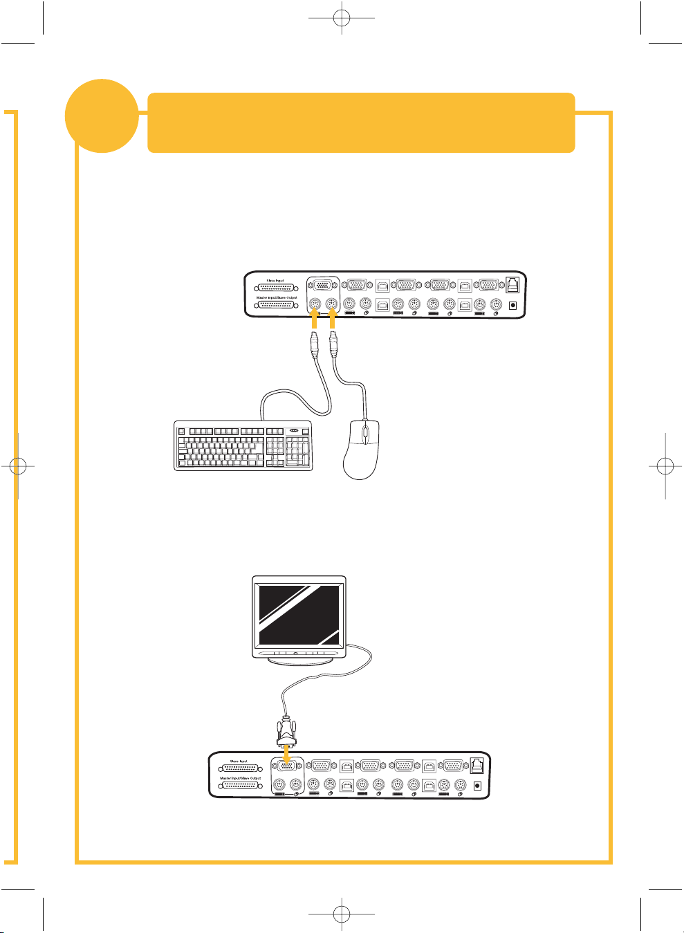
Connecting the Keyboard, Video, and Mouse
1
1. Power down all computers.
2. Connect the PS/2-type keyboard and mouse to the Console ports located
on the back panel of the Switch.
to the Console Ports on the Switch
VGA
04
VGA
04
USB
USB
03
04
03
VGA
02
VGA
03
02
01
VGA
02
USB
01
USB
01
F10
F9
F11
num
cap
lock
lock
2
]
[
P
;:
K
L
return
'"
shift clt
=
09
76543
8
1
pg up
=
-
/
PG DN
HOME
PG UP
delete
8
7
9
`
CAPS
HELP
+
4
5
6
OPT
ESC
PC
1
2
3
^
+
<
0
>
alt
3. Connect the video cable that is attached to the monitor, to the Console
video port located on the back panel of the Switch.
VGA
04
VGA
04
03
VGA
04
USB
USB
03
02
VGA
03
02
01
VGA
02
USB
01
USB
01
Page 6
P74183ea_F1DZ102-104_QIG.qxd 16-04-2003 10:02 Page 4
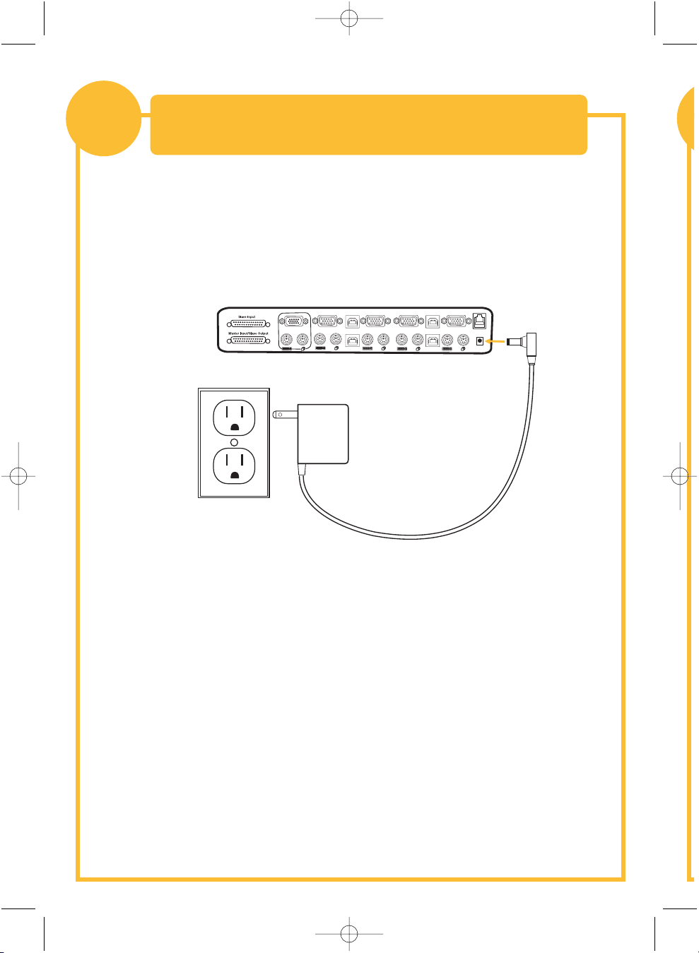
Powering Up the Switch
2
1. Connect the included 12V DC, 1A power supply unit into an available
power outlet.
2. Attach the barrel plug into the power jack located on the rear of the
Switch to power the unit.
VGA
04
VGA
04
03
VGA
02
04
USB
USB
03
VGA
03
02
01
VGA
02
USB
01
USB
01
The LEDs should illuminate.
Page 7

P74183ea_F1DZ102-104_QIG.qxd 16-04-2003 10:02 Page 5
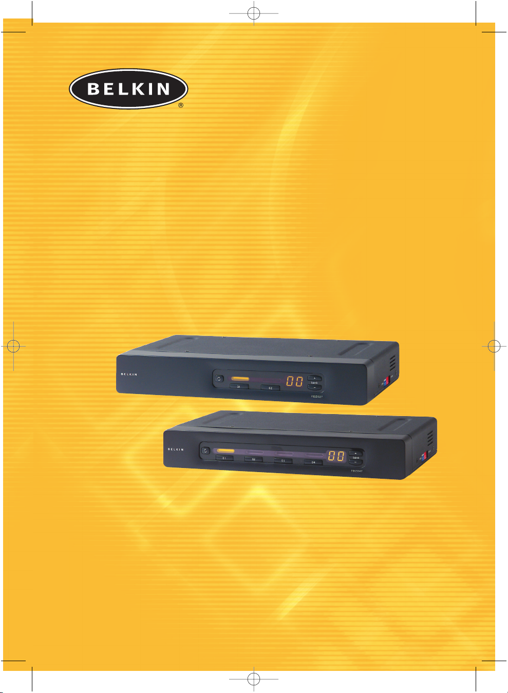
Connecting Computers to the Switch
3
1. Using an OmniView KVM Cable*, connect the male end of the VGA cable to
the VGA port on the first computer. Connect the female end to the VGA
port on the back of the Switch for CPU1.
(Video and PS/2 Connection)
VGA
04
03
VGA
02
VGA
04
VGA
01
04
USB
USB
03
03
VGA
02
USB
01
USB
02
01
2. Connect one end of the PS/2 keyboard KVM cable* to the keyboard port
on the computer and the other end to the CPU1 keyboard port
on the back of the Switch.
3. Connect one end of the PS/2 mouse KVM cable* to the mouse port
on the computer and the other end to the CPU1 mouse port on the back
of the Switch.
Repeat steps 1 through 3 for each additional computer to be connected to the
Switch, connecting them to the corresponding CPU ports on the back.
*Please refer to the first page for part numbers.
Page 8

VGA
VGA
VGA
VGA
VGA
USB
USB
USB
USB
04
04
04
03
03
03
02
02
02
01
01
01
P74183ea_F1DZ102-104_QIG.qxd 16-04-2003 10:02 Page 6
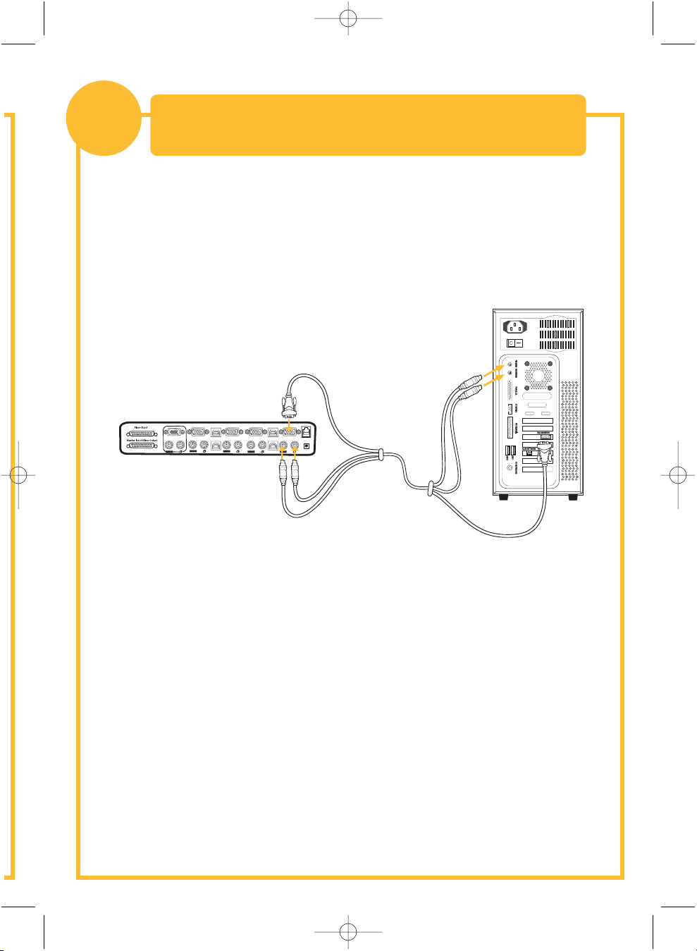
Connecting Computers to the Switch
4
1. Boot the computer you wish to connect via USB as you would normally
with the keyboard, monitor, and mouse connected directly
to the computer.
2. After the operating system finishes loading, connect the Switch to the
USB computer using the USB A-to-B part of your USB KVM cable*. Your
computer should recognize your Switch and automatically install the HID
USB driver. Once the driver is installed, you can power down your
computer and prepare to connect it to the Switch.
3. Plug in the male VGA connector of a KVM cable to the VGA port on the
computer. Connect the other end (the female connector) of the VGA cable
to the back of the Switch for the appropriate port.
(Video and USB Connection)
4. Connect the USB cable’s A-type connector to an available USB port on
your USB computer. Connect the other end of the USB cable
(with the B-type connector) to the corresponding port on the back
of the Switch.
Repeat steps 1 through 4 for each additional USB computer you wish
to connect.
Power on all connected computers. The Switch is now ready for use.
*Please refer to the first page for part numbers.
Page 9
P74183ea_F1DZ102-104_QIG.qxd 16-04-2003 10:02 Page 7
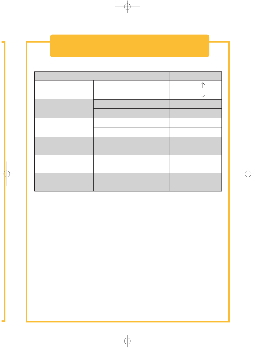
Hot Key Commands – Quick Reference
Functions Commands
Switch PORTS
Previous Active PORT
ScrLk + ScrLk +
Next Active PORT
Switch BANKS
(By default, selects first
active port on the BANK)
Directly switch to PORT
(Single-Switch Configuration)
Directly switch to
PORT Y on BANK X
(Daisy-Chain Configuration)
Enable/disable sound
Enable AutoScan mode
Switch to Previous BANK
Switch to Next BANK
F1DZ102T (Y=01 to 02)
F1DZ104T (Y=01 to 04)
F1DZ102T (X=00 to 03) (Y=01 to 02)
F1DZ104T (X=00 to 03) (Y=01 to 04)
Please refer to your User Manual for additional information.
ScrLk + ScrLk +
ScrLk + ScrLk + Page Up
ScrLk + ScrLk +
ScrLk + ScrLk + Y
ScrLk + ScrLk + Y
ScrLk + ScrLk + X + Y
ScrLk + ScrLk + X + Y
ScrLk + ScrLk + S
ScrLk + ScrLk + A
Page Down
Page 10
P74183ea_F1DZ102-104_QIG.qxd 16-04-2003 10:02 Page 8
belkin.com
Belkin Corporation
501 West Walnut Street
Compton • CA • 90220 • USA
Tel: +1 310.898.1100
Fax: +1 310.898.1111
Belkin Components, Ltd.
Express Business Park
Shipton Way • Rushden • NN10 6GL
United Kingdom
Tel: +44 (0) 1933 35 2000
Fax: +44 (0) 1933 31 2000
Belkin Components B.V.
Starparc Building • Boeing Avenue 333
1119 PH Schiphol-Rijk • The Netherlands
Tel: +31 (0) 20 654 7300
Fax: +31 (0) 20 654 7349
Belkin GmbH
Hanebergstrasse 2
80637 München • Germany
Tel.: +49 (0) 89 1434050
Fax: +49 (0) 89 143405100
Belkin Tech Support
US: +1 310.898.1100 ext. 2263
+1 800.223.5546 ext. 2263
Europe: 00 800 223 55 460
Australia: 1800 666 040
P74183
© 2003 Belkin Corporation. All rights reserved. All trade names are
registered trademarks of respective manufacturers listed.
Page 11
P74183ea_F1DZ102-104_QIG.qxd 16-04-2003 10:02 Page 1
™
OmniView
Switch KVM
Commandez jusqu’à quatre ordinateurs
à partir d'une seule console PS/2
Guide d’installation rapide
SE Plus Series
F1DZ102T
F1DZ104T
Page 12

P74183ea_F1DZ102-104_QIG.qxd 16-04-2003 10:02 Page 2
Introduction
Cette feuille vous guidera à travers les principales étapes nécessaires à
l’installation du Switch KVM OmniView SE Plus. En cas de problème pendant
l’installation, reportez-vous au manuel de l’utilisateur SE Plus.
L’installation du Switch SE Plus requiert les éléments suivants :
• Switch KVM OmniView SE Plus
• Un clavier, une souris et un moniteur PS/2
• Un câble KVM par ordinateur installé
• Un bloc d’alimentation 12 V CC, 1 A
Kits de câbles recommandés :
F3X1105-XX Câble PS/2
F3X1835-XX-GLD Câble PS/2
F3X1962-XX Câble USB
F3X1895-XX-GLD Câble USB
F1D108-CBL Câble d’interconnexion en chaîne
(-XX indique la longueur, en pieds)
Page 13

P74183ea_F1DZ102-104_QIG.qxd 16-04-2003 10:02 Page 3
Raccordement du clavier, de la souris
1
1. Mettez tous les ordinateurs hors tension.
2. Raccordez le clavier et la souris PS/2 aux ports situés
sur le panneau arrière du Switch.
et du moniteur aux ports du Switch
VGA
04
VGA
04
USB
USB
03
04
03
VGA
02
VGA
03
02
01
VGA
02
USB
01
USB
01
F10
F9
F11
num
cap
lock
lock
2
]
[
P
;:
K
L
return
'"
shift clt
=
09
76543
8
1
pg up
=
-
/
PG DN
HOME
PG UP
delete
8
7
9
`
CAPS
HELP
+
4
5
6
OPT
ESC
PC
1
2
3
^
+
<
0
>
alt
3. Branchez le câble vidéo raccordé au moniteur sur le port vidéo
situé sur le panneau arrière du Switch.
VGA
04
VGA
04
03
VGA
04
USB
USB
03
02
VGA
03
02
01
VGA
02
USB
01
USB
01
Page 14

P74183ea_F1DZ102-104_QIG.qxd 16-04-2003 10:02 Page 4
Mise sous tension du Switch
2
1. Branchez le bloc d'alimentation 12 V CC, 1 A fourni sur une prise
secteur libre.
2. Raccordez la fiche cylindrique à la prise d'alimentation située à l’arrière
du Switch afin d’alimenter l’appareil.
VGA
04
VGA
04
03
VGA
02
04
USB
USB
03
VGA
03
02
01
VGA
02
USB
01
USB
01
Les témoins lumineux doivent s’allumer.
Page 15
P74183ea_F1DZ102-104_QIG.qxd 16-04-2003 10:02 Page 5
Raccordement des ordinateurs au Switch
3
1. Avec un câble KVM OmniView*, branchez l’extrémité mâle du câble VGA
sur le port VGA du premier ordinateur. Raccordez l’extrémité femelle au
port VGA CPU1 à l’arrière du Switch.
(connexion vidéo et PS/2)
VGA
04
03
VGA
02
VGA
04
VGA
01
04
USB
USB
03
03
VGA
02
USB
01
USB
02
01
2. Branchez une extrémité du câble KVM clavier PS/2* sur le port clavier
de l’ordinateur, et l’autre sur le port clavier CPU1 à l’arrière du Switch.
3. Raccordez une extrémité du câble KVM souris PS/2* au port souris
de l’ordinateur et l’autre au port souris CPU1 à l’arrière du Switch.
Répétez les étapes 1 à 3 pour chaque ordinateur à raccorder au Switch,
en les branchant sur les ports CPU correspondants à l’arrière du boîtier.
*Pour les références d'article, reportez-vous à la première page.
Page 16
VGA
VGA
VGA
VGA
VGA
USB
USB
USB
USB
04
04
04
03
03
03
02
02
02
01
01
01
P74183ea_F1DZ102-104_QIG.qxd 16-04-2003 10:02 Page 6
Raccordement des ordinateurs au Switch
4
1. Allumez l’ordinateur à raccorder via USB comme habituellement,
le clavier, le moniteur et la souris étant raccordés directement
à l’ordinateur.
2. Une fois le chargement du système d’exploitation terminé, raccordez
le Switch à l’ordinateur USB à l’aide de la partie USB A-B du câble KVM
USB*. L’ordinateur doit reconnaître le Switch et installer automatiquement
les pilotes USB HID. Lorsque les pilotes sont installés, vous pouvez
éteindre l’ordinateur et préparer son raccordement au Switch.
3. Branchez le connecteur VGA mâle du câble KVM sur le port VGA
de l’ordinateur. Raccordez l’autre extrémité (le connecteur femelle)
du câble VGA au port approprié à l'arrière du Switch.
(connexion vidéo et USB)
4. Branchez le connecteur A du câble USB sur un port USB libre de
l’ordinateur USB. Raccordez l’autre extrémité du câble USB (avec le
connecteur B) au port correspondant du panneau arrière du Switch.
Répétez les étapes 1 à 4 pour chaque
ordinateur USB supplémentaire à raccorder.
Allumez tous les ordinateurs connectés. Le Switch est prêt à être utilisé.
*Pour les références d'article, reportez-vous à la première page.
Page 17

P74183ea_F1DZ102-104_QIG.qxd 16-04-2003 10:02 Page 7
Raccourcis clavier – aide-mémoire
Fonctions Commands
PORTS du Switch
PORT actif précédent
Arrêt défil + Arrêt défil +
Arrêt défil + Arrêt défil +
Arrêt défil + Arrêt défil + PgPréc
Arrêt défil + Arrêt défil + PgSuiv
Arrêt défil + Arrêt défil + Y
Arrêt défil + Arrêt défil + Y
Arrêt défil + Arrêt défil + X + Y
Arrêt défil + Arrêt défil + X + Y
Arrêt défil + Arrêt défil + S
Arrêt défil + Arrêt défil + A
BANCS du Switch (par défaut,
sélection du premier port
actif sur le BANC)
Commutation directe sur
le PORT (configuration
à un seul Switch)
Commutation directe sur
le PORT Y du BANC X
(connexion en chaîne)
Activation/désactivation du son
Activation du balayage
automatique des ports AutoScan
PORT actif suivant
Commutation au BANC précédent
Commutation au BANC suivant
F1DZ102T (Y = 01 à 02)
F1DZ104T (Y = 01 à 04)
F1DZ102T (X = 00 à 03) (Y = 01 à 02)
F1DZ104T (X = 00 à 03) (Y = 01 à 04)
Pour plus d’informations, reportez-vous au manuel de l’utilisateur.
Page 18

P74183ea_F1DZ102-104_QIG.qxd 16-04-2003 10:02 Page 8
belkin.com
Belkin Corporation
501 West Walnut Street
Compton • CA • 90220 • USA
Tel: +1 310.898.1100
Fax: +1 310.898.1111
Belkin Components, Ltd.
Express Business Park
Shipton Way • Rushden • NN10 6GL
Royaume-Uni
Tel: +44 (0) 1933 35 2000
Fax: +44 (0) 1933 31 2000
Belkin Components B.V.
Starparc Building • Boeing Avenue 333
1119 PH Schiphol-Rijk • Pays-Bas
Tel: +31 (0) 20 654 7300
Fax: +31 (0) 20 654 7349
Belkin GmbH
Hanebergstrasse 2
80637 München • Allemagne
Tel.: +49 (0) 89 1434050
Fax: +49 (0) 89 143405100
Assistance technique Belkin
US: +1 310.898.1100 poste 2263
+1 800.223.5546 poste 2263
Europe: 00 800 223 55 460
Australia: 1800 666 040
P74183
Tous les noms de marque sont des marques déposées des fabricants respectifs énumérés.
© 2003 Belkin Corporation. Tous droits réservés.
Page 19

P74183ea_F1DZ102-104_QIG.qxd 16-04-2003 10:02 Page 1
™
OmniView
Masterswitch
Zur Kontrolle von bis zu vier
Computern mit nur einer PS/2-Konsole
Anleitung für Schnellinstallation
SE Plus Series
F1DZ102T
F1DZ104T
Page 20

P74183ea_F1DZ102-104_QIG.qxd 16-04-2003 10:02 Page 2
Einführung
Diese Kurzanleitung führt Sie durch die wesentlichen Schritte der Installation
des Masterswitches aus der OmniView SE Plus Series (des Switches).
Wenn es bei der Installation zu Problemen kommt, finden Sie weitere
Informationen im SE-Plus-Series-Benutzerhandbuch.
Zur Installation des SE-Plus-Masterswitch wird folgendes benötigt:
• OmniView-SE-Plus-Series-Masterswitch
• Eine PS/2-Tastatur, ein Bildschirm und eine PS/2-Maus
• Ein Masterswitch-Kabel für jeden installierten Computer
• Ein Netzteil (12 V Gleichstrom, 1 A Wechselstrom)
Empfohlene Kabelsätze:
F3X1105-XX PS/2-Ausführung
F3X1835-XX-GLD PS/2-Ausführung
F3X1962-XX USB-Ausführung
F3X1895-XX-GLD USB-Ausführung
F1D108-CBL Kaskadierungskabel
(XX = Länge gemessen in Fuß)
Page 21

P74183ea_F1DZ102-104_QIG.qxd 16-04-2003 10:02 Page 3
Anschließen der Tastatur, des Monitors und
1
1. Schalten Sie alle Computer ab.
2. Verbinden Sie die PS/2-Tastatur und das PS/2-Mauskabel
mit den Konsolen-Ports an der Rückseite des Masterswitches.
der Maus an die Konsolen-Ports am Switch
VGA
04
VGA
04
USB
USB
03
04
03
VGA
02
VGA
03
02
01
VGA
02
USB
01
USB
01
F10
F9
F11
num
cap
lock
lock
2
]
[
P
;:
K
L
return
'"
shift clt
=
09
76543
8
1
pg up
=
-
/
PG DN
HOME
PG UP
delete
8
7
9
`
CAPS
HELP
+
4
5
6
OPT
ESC
PC
1
2
3
^
+
<
0
>
alt
3. Verbinden Sie das Monitorkabel des Bildschirms mit der
Konsolen-Monitorschnittstelle an der Rückseite des Switches.
VGA
04
VGA
04
03
VGA
04
USB
USB
03
02
VGA
03
02
01
VGA
02
USB
01
USB
01
Page 22

P74183ea_F1DZ102-104_QIG.qxd 16-04-2003 10:02 Page 4
Hochfahren des Switches
2
1. Schließen Sie das enthaltene Netzteil
(12 V Gleichstrom, 1 A Wechselstrom) an eine freie Steckdose an.
2. Stecken Sie den runden Stecker in den Netzanschluss
an der Rückseite des Switches, um ihn mit dem Netz zu verbinden.
VGA
04
VGA
04
03
VGA
04
USB
USB
03
VGA
03
02
02
01
VGA
02
USB
01
USB
01
Jetzt leuchten die LEDs auf.
Page 23

P74183ea_F1DZ102-104_QIG.qxd 16-04-2003 10:02 Page 5
Anschließen von Computern an den Switch
3
1. Verbinden Sie das OmniView-Masterswitch-Kabel* mit dem Stecker des
VGA-Kabels und mit dem VGA-Port des ersten Computers. Verbinden Sie die
Buchse des VGA-Ports mit dem Port "CPU1" an der Rückseite des Switches.
(Bildschirm- und PS/2-Anschluss)
VGA
04
03
VGA
02
VGA
04
VGA
01
04
USB
USB
03
03
VGA
02
USB
01
USB
02
01
2. Verbinden Sie das PS/2-Masterswitch-Tastaturkabel* mit dem Tastatur-Port
des Computers und dem CPU1-Tastatur-Port an der Rückseite des Switches.
3. Verbinden Sie das PS/2-Masterswitch-Mauskabel* mit dem Maus-Port
des Computers und dem CPU1-Maus-Port an der Rückseite des Switches.
Wiederholen Sie die Schritte 1 bis 3 für jeden weiteren Computer, den Sie an
den Switch anschließen möchten, und verwenden Sie hierzu die entsprechenden
Computerschnittstellen ("CPU") an der Rückseite.
* Die entsprechenden Teilenummern finden Sie auf der ersten Seite.
Page 24

VGA
VGA
VGA
VGA
VGA
USB
USB
USB
USB
04
04
04
03
03
03
02
02
02
01
01
01
P74183ea_F1DZ102-104_QIG.qxd 16-04-2003 10:02 Page 6
Anschließen von Computern an den Switch
4
1. Fahren Sie den Computer hoch, den Sie über USB anschließen möchten.
Lassen Sie dabei Tastatur, Bildschirm und Maus wie sonst direkt am
Computer angeschlossen.
2. Nachdem das Betriebssystem hochgefahren ist, schließen Sie den Switch
mit Hilfe des USB-A/B-Kabels im USB-Masterswitch-Kabelsatz* an den
USB-Computer an. Ihr Computer müßte jetzt den Switch erkennen und
den HID-USB-Treiber automatisch installieren. Nach der Installation des
Treibers können Sie den Computer herunterfahren und ihn dann mit dem
Switch verbinden.
3. Stecken Sie den VGA-Stecker eines Masterswitch-Kabels in den VGA-Port
des Computers. Stecken Sie das andere Ende (die Buchse) des VGA-Kabels
in den entsprechenden Port an der Rückseite des Switches.
(Bildschirm- und USB-Anschluss)
4. Stecken Sie den A-Stecker des USB-Kabels in einen freien USB-Port
an Ihrem USB-Computer. Stecken Sie das andere Ende des USB-Kabels
(den B-Stecker) in den entsprechenden Port an
der Rückseite des Switches.
Wiederholen Sie Schritt 1 bis 4 für jeden weiteren anzuschließenden
USB-Computer anschliessen.
Schalten Sie alle angeschlossenen Computer ein. Jetzt
können Sie den Switch nutzen.
* Die entsprechenden Teilenummern finden Sie auf der ersten Seite.
Page 25

P74183ea_F1DZ102-104_QIG.qxd 16-04-2003 10:02 Page 7
Tastaturbefehle: Kurzübersicht
Funktionen Befehle
PORT wechseln
Vorheriger aktiver PORT
Rollen + Rollen +
BANK wechseln (Standardmäßig
wird der erste aktive Port der
BANK ausgewählt.)
Direkt zu einem PORT wechseln
(Einzelgerät-Konfiguration)
Direktes Umschalten zu PORT Y
an BANK X (Kaskadierung)
Ton aktivieren/deaktivieren
AutoScan-Modus aktivieren
Nächster aktiver PORT
Zurückschalten zur vorherigen BANK
Weiterschalten zur nächsten BANK
F1DZ102T (Y=01 bis 02)
F1DZ104T (Y=01 bis 04)
F1DZ102T (X=00 bis 03) (Y=01 bis 02)
F1DZ104T (X=00 bis 03) (Y=01 bis 04)
Rollen + Rollen +
Rollen + Rollen + Bild auf
Rollen + Rollen + Bild ab
Rollen + Rollen + Y
Rollen + Rollen + Y
Rollen + Rollen + X + Y
Rollen + Rollen + X + Y
Rollen + Rollen + S
Rollen + Rollen + A
Weitere Informationen hierzu finden Sie im Benutzerhandbuch.
Page 26

P74183ea_F1DZ102-104_QIG.qxd 16-04-2003 10:02 Page 8
belkin.com
Belkin Corporation
501 West Walnut Street
Compton • CA • 90220 • USA
Tel: +1 310.898.1100
Fax: +1 310.898.1111
Belkin Components, Ltd.
Express Business Park
Shipton Way • Rushden • NN10 6GL
Großbritannien
Tel: +44 (0) 1933 35 2000
Fax: +44 (0) 1933 31 2000
Belkin Components B.V.
Starparc Building • Boeing Avenue 333
1119 PH Schiphol-Rijk • Niederlande
Tel: +31 (0) 20 654 7300
Fax: +31 (0) 20 654 7349
Belkin GmbH
Hanebergstrasse 2
80637 München • Deutschland
Tel.: +49 (0) 89 1434050
Fax: +49 (0) 89 143405100
Belkin-Kundendienst
US: +1 310.898.1100 Durchwahl: 2263
+1 800.223.5546 Durchwahl: 2263
Europe: 00 800 223 55 460
Australia: 1800 666 040
P74183
© 2003 Belkin Corporation. Alle Rechte vorbehalten. Alle Warenzeichen
sind eingetragene Warenzeichen der angegebenen Hersteller.
Page 27

P74183ea_F1DZ102-104_QIG.qxd 16-04-2003 10:02 Page 1
™
OmniView
KVM-switch
Bestuur maximaal vier computers vanaf één PS/2-console
Installatiehandleiding
SE Plus Series
F1DZ102T
F1DZ104T
Page 28

P74183ea_F1DZ102-104_QIG.qxd 16-04-2003 10:02 Page 2
Inleiding
Dit blad begeleidt u door de basisstappen die u moet uitvoeren voor
de installatie van de OmniView SE Plus-serie kvm-switch (de switch).
Raadpleeg de handleiding bij de SE Plus-serie als u problemen ondervindt
bij de installatie.
U hebt het volgende nodig om de SE Plus te installeren:
• OmniView SE Plus-serie kvm-switch
• Een PS/2-toetsenbord, -muis en –monitor (elk)
• Eén KVM-kabel per aangesloten computer
• Eén12V DC, 1A netvoedingseenheid
Aanbevolen kabelsets:
F3X1105-XX PS/2
F3X1835-XX-GLD PS/2
F3X1962-XX USB
F3X1895-XX-GLD USB
F1D108-CBL Daisy-chainkabel:
(-XX geeft de lengte in voet aan)
Page 29

P74183ea_F1DZ102-104_QIG.qxd 16-04-2003 10:02 Page 3
Toetsenbord, monitor en muis aansluiten
1
1. Schakel alle computers uit.
2. Sluit het PS/2-toetsenbord en de PS/2-muis
aan op de consolepoorten in het achterpaneel van de switch.
via de consolepoorten op de switch
VGA
04
VGA
04
USB
USB
03
04
03
VGA
02
VGA
03
02
01
VGA
02
USB
01
USB
01
F10
F9
F11
num
cap
lock
lock
2
]
[
P
;:
K
L
return
'"
shift clt
=
09
76543
8
1
pg up
=
-
/
PG DN
HOME
PG UP
delete
8
7
9
`
CAPS
HELP
+
4
5
6
OPT
ESC
PC
1
2
3
^
+
<
0
>
alt
3. Sluit de videokabel die bevestigd is aan de monitor aan
op de videopoort van de console, in het achterpaneel van de switch.
VGA
04
VGA
04
03
VGA
04
USB
USB
03
02
VGA
03
02
01
VGA
02
USB
01
USB
01
Page 30

P74183ea_F1DZ102-104_QIG.qxd 16-04-2003 10:02 Page 4
De switch inschakelen
2
1. Sluit de meegeleverde 12V DC 1A
netvoedingseenheid aan op een vrij stopcontact.
2. Steek de trommelstekker in de netvoedingsaansluiting aan
de achterkant van de switch om de eenheid van voeding te voorzien.
VGA
04
VGA
04
03
VGA
04
USB
USB
03
VGA
03
02
02
01
VGA
02
USB
01
USB
01
De lampjes moeten nu gaan branden.
Page 31

P74183ea_F1DZ102-104_QIG.qxd 16-04-2003 10:02 Page 5
Computers aansluiten op de switch
3
1. Neem een OmniView KVM-kabel* en sluit de connector met pinnen van
de VGA-kabel aan op de VGA-poort op de eerste computer. Sluit het andere
eind aan op de VGA-poort aan de achterkant van de switch voor CPU1.
(video- en PS/2-aansluiting)
VGA
04
03
VGA
02
VGA
04
VGA
01
04
USB
USB
03
03
VGA
02
USB
01
USB
02
01
2. Sluit het ene eind van de KVM-kabel* voor het PS/2-toetsenbord aan
op de toetsenbordaansluiting op de computer en het andere eind op
de toetsenbordaansluiting van CPU1 aan de achterkant van de switch.
3. Sluit het ene eind van de KVM-kabel* voor de PS/2-muis aan
op de muisaansluiting op de computer en het andere eind op
de muisaansluiting van CPU1 aan de achterkant van de switch.
Herhaal stap 1 tot en met 3 voor elke volgende computer die u wilt aansluiten
op de switch, waarbij u ze aansluit op de desbetreffende CPU-poorten aan de
achterkant.
*Zie de eerste pagina voor de artikelnummers.
Page 32

VGA
VGA
VGA
VGA
VGA
USB
USB
USB
USB
04
04
04
03
03
03
02
02
02
01
01
01
P74183ea_F1DZ102-104_QIG.qxd 16-04-2003 10:02 Page 6
Computers aansluiten op de switch
4
1. Start de computer op die u wilt aansluiten via de USB-aansluiting
zoals u zou doen wanneer het toetsenbord, de monitor en de muis
rechtstreeks zijn aangesloten op de computer.
2. Nadat het besturingssysteem is geladen, sluit u de switch aan op
de USB-computer met het USB A-naar-B-gedeelte van de USB kvm-kabel*.
Uw computer herkent in principe uw switch en zal automatisch het HID
USB-stuurprogramma installeren. Als het stuurprogramma is geïnstalleerd,
kunt u de computer uitschakelen en deze voorbereiden voor aansluiting
op de switch.
3. Sluit de VGA-connector met pinnen van een kvm-kabel aan
op de VGA-poort van de computer. Sluit het andere eind van
de VGA-kabel aan op de achterkant van de switch voor de juiste poort.
(VGA en USB-aansluiting)
4. Sluit de A-stekker van de USB-kabel aan op een vrije USB-aansluiting
van uw USB-computer. Sluit het andere eind van de USB-kabel
(met een B-type connector) aan op de desbetreffende aansluiting
aan de achterkant van de switch.
Herhaal stap 1 tot en met 4 voor elke volgende USB-computer
die u op de switch wilt aansluiten.
Schakel alle aangesloten computers in. De switch is nu klaar voor gebruik.
*Zie de eerste pagina voor de artikelnummers.
Page 33

P74183ea_F1DZ102-104_QIG.qxd 16-04-2003 10:02 Page 7
Sneltoetsopdrachten: kort overzicht
Functies Opdrachten
Naar een andere
poort overschakelen
Vorige actieve poort
Volgende actieve poort
ScrLk + ScrLk +
ScrLk + ScrLk +
Naar een andere bank overschakelen
(selecteert standaard de eerste
actieve poort op de bank)
Meteen overschakelen naar
de poort (in een configuratie
met één switch)
Meteen overschakelen
naar poort Y op bank X
(in een daisy-chainconfiguratie)
Geluid in-/uitschakelen
AutoScan-modus inschakelen
Overschakelen naar vorige bank
Overschakelen naar volgende bank
F1DZ102T (Y=01 t/m 02)
F1DZ104T (Y=01 t/m 04)
F1DZ102T (X=00 t/m 03) (Y=01 t/m 02)
F1DZ104T (X=00 t/m 03) (Y=01 t/m 04)
Meer informatie vindt u in de handleiding.
ScrLk + ScrLk + Page Up
ScrLk + ScrLk + Page Down
ScrLk + ScrLk + Y
ScrLk + ScrLk + Y
ScrLk + ScrLk + X + Y
ScrLk + ScrLk + X + Y
ScrLk + ScrLk + S
ScrLk + ScrLk + A
Page 34

P74183ea_F1DZ102-104_QIG.qxd 16-04-2003 10:02 Page 8
belkin.com
Belkin Corporation
501 West Walnut Street
Compton • CA • 90220 • USA
Tel: +1 310.898.1100
Fax: +1 310.898.1111
Belkin Components, Ltd.
Express Business Park
Shipton Way • Rushden • NN10 6GL
Verenigd Koningrijk
Tel: +44 (0) 1933 35 2000
Fax: +44 (0) 1933 31 2000
Belkin Components B.V.
Starparc Building • Boeing Avenue 333
1119 PH Schiphol-Rijk • Nederland
Tel: +31 (0) 20 654 7300
Fax: +31 (0) 20 654 7349
Belkin GmbH
Hanebergstrasse 2
80637 München • Duitsland
Tel.: +49 (0) 89 1434050
Fax: +49 (0) 89 143405100
Belkin Tech Support
US: +1 310.898.1100 tstl. 2263
+1 800.223.5546 tstl. 2263
Europe: 00 800 223 55 460
Australia: 1800 666 040
P74183
© 2003 Belkin Corporation. Alle rechten voorbehouden. Alle handelsnamen
zijn geregistreerde handelsmerken van de betreffende rechthebbenden.
Page 35

P74183ea_F1DZ102-104_QIG.qxd 16-04-2003 10:02 Page 1
™
OmniView
Conmutador KVM
Controla hasta cuatro ordenadores desde una consola PS/2
Guía de instalación Rápida
SE Plus Series
F1DZ102T
F1DZ104T
Page 36

P74183ea_F1DZ102-104_QIG.qxd 16-04-2003 10:02 Page 2
Introducción
Esta hoja le guiará a través de los pasos básicos necesarios para instalar
el conmutador KVM OmniView de la serie SE Plus (el conmutador). Si tiene
algún problema durante la instalación, por favor consulte el Manual de usuario
de la serie SE Plus.
Son necesarios los siguientes elementos para instalar SE Plus:
• Conmutador KVM OmniView serie SE Plus
• Un (cada uno) teclado PS/2, monitor y ratón
• Un cable KVM por cada ordenador instalado
•Una fuente de alimentación de 12 VCC, 1A
Kits de cables recomendados:
F3X1105-XX Estilo PS/2
F3X1835-XX-GLD Estilo PS/2
F3X1962-XX Estilo USB
F3X1895-XX-GLD Estilo USB
F1D108-CBL Cable de conexión en bus
(-XX indica la longitud en pies)
Page 37

P74183ea_F1DZ102-104_QIG.qxd 16-04-2003 10:02 Page 3
Conectando el teclado, vídeo y ratón en
1
1. Apague todos los ordenadores.
2. Conecte el teclado tipo PS/2 y el ratón en los puertos
de la consola localizados en el panel posterior del Conmutador.
los puertos de la consola en el conmutador
VGA
04
VGA
04
USB
USB
03
04
03
VGA
02
VGA
03
02
01
VGA
02
USB
01
USB
01
F10
F9
F11
num
cap
lock
lock
2
]
[
P
;:
K
L
return
'"
shift clt
=
09
76543
8
1
pg up
=
-
/
PG DN
HOME
PG UP
delete
8
7
9
`
CAPS
HELP
+
4
5
6
OPT
ESC
PC
1
2
3
^
+
<
0
>
alt
3. Conecte el cable de vídeo que sale del monitor en el puerto de vídeo
de la consola localizado en el panel posterior del conmutador.
VGA
04
VGA
04
03
VGA
04
USB
USB
03
02
VGA
03
02
01
VGA
02
USB
01
USB
01
Page 38

P74183ea_F1DZ102-104_QIG.qxd 16-04-2003 10:02 Page 4
Encendido del conmutador
2
1. Conecte la fuente de alimentación de 12 VCC, 1A
a una toma de corriente disponible.
2. Conecte el conector de tipo barril en la clavija de alimentación localizado
en la parte posterior del conmutador para encender la unidad.
VGA
04
VGA
04
03
VGA
02
04
USB
USB
03
VGA
03
02
01
VGA
02
USB
01
USB
01
Los indicadores LED deberán iluminar.
Page 39

P74183ea_F1DZ102-104_QIG.qxd 16-04-2003 10:02 Page 5
Conectando ordenadores al conmutador
3
1. Utilizando un cable OmniView KVM *, conecte el extremo macho del cable
VGA al puerto VGA en el primer ordenador. Conecte el extremo hembra en
el puerto VGA en la parte posterior del conmutador para la CPU1.
(conexión de vídeo y PS/2)
VGA
04
03
VGA
02
VGA
04
VGA
01
04
USB
USB
03
03
VGA
02
USB
01
USB
02
01
2. Conecte un extremo del cable * KVM de teclado PS/2 en el puerto
de teclado del ordenador y el otro extremo en el puerto de teclado
CPU1 en la parte posterior del conmutador.
3. Conecte un extremo del cable * KVM del ratón PS/2 en el puerto
de ratón del ordenador y el otro extremo en el puerto de ratón CPU1
en la parte posterior del conmutador.
Repita los pasos 1 a 3 para cada ordenador adicional que se conecte
al conmutador, conectándolos en los puertos CPU correspondientes
en la parte posterior.
*Por favor consulte la primera página para los números de piezas.
Page 40

VGA
VGA
VGA
VGA
VGA
USB
USB
USB
USB
04
04
04
03
03
03
02
02
02
01
01
01
P74183ea_F1DZ102-104_QIG.qxd 16-04-2003 10:02 Page 6
Conectando ordenadores al Conmutador
4
1. Arranque el ordenador que desee conectar mediante USB
como lo haría normalmente con el teclado, monitor y ratón
conectados directamente al ordenador.
2. Cuando el sistema operativo termine de cargar, conecte el conmutador
en el ordenador USB utilizando la parte USB A a B del cable* KVM USB.
Su ordenador deberá reconocer el conmutador automáticamente e instalar
el controlador HID USB. Cuando el controlador esté instalado, podrá
apagar su ordenador y prepararlo para conectarlo al conmutador.
3. Conecte el conector VGA macho del cable KVM al puerto VGA en el
ordenador. Conecte el otro extremo (el conector hembra) del cable
VGA en la parte posterior del conmutador en el puerto apropiado.
(conexión de vídeo y USB)
4. Conecte el conector tipo A del cable USB en un puerto USB disponible en
su ordenador. Conecte el otro extremo del cable USB (con el conector de
tipo B) en el puerto correspondiente en la parte posterior del conmutador.
Repita los pasos 1 y 4 para cada ordenador
adicional con puerto USB que desee conectar.
Encienda todos los ordenadores conectados.
El conmutador está ahora listo para ser utilizado.
*Por favor consulte la primera página para los números de piezas.
Page 41

P74183ea_F1DZ102-104_QIG.qxd 16-04-2003 10:02 Page 7
Comandos de acceso rápido – Guía de referencia
Funciones Comandos
PUERTOS del conmutador
PUERTO activo anterior
BloqDespl + BloqDespl +
BANCOS del conmutador (como
opción predefinida se selecciona el
primer puerto activo del BANCO)
Conmutación directa al PUERTO
(Configuración de Conmutador
único)
Conmutación directa al PUERTO Y
del BANCO X (Configuración en
bus)
Activa/desactiva el sonido
Activa el modo AutoScan
PUERTO activo siguiente
Conmutar al BANCO anterior
Conmutar al BANCO siguiente
F1DZ102T (Y=01 a 02)
F1DZ104T (Y=01 a 04)
F1DZ102T (X=00 a 03) (Y=01 a 02)
F1DZ104T (X=00 a 03) (Y=01 a 04)
BloqDespl + BloqDespl +
BloqDespl + BloqDespl + Av. Pág«
BloqDespl + BloqDespl + Re Pág«
BloqDespl + BloqDespl + Y
BloqDespl + BloqDespl + Y
BloqDespl + BloqDespl + X + Y
BloqDespl + BloqDespl + X + Y
BloqDespl + BloqDespl + S
BloqDespl + BloqDespl + A
Consulte el manual de usuario para obtener información adicional.
Page 42

P74183ea_F1DZ102-104_QIG.qxd 16-04-2003 10:03 Page 8
belkin.com
Belkin Corporation
501 West Walnut Street
Compton • CA • 90220 • EEUU
Tel: +1 310.898.1100
Fax: +1 310.898.1111
Belkin Components, Ltd.
Express Business Park
Shipton Way • Rushden • NN10 6GL
Reino Unido
Tel: +44 (0) 1933 35 2000
Fax: +44 (0) 1933 31 2000
Belkin Components B.V.
Starparc Building • Boeing Avenue 333
1119 PH Schiphol-Rijk • Holanda
Tel: +31 (0) 20 654 7300
Fax: +31 (0) 20 654 7349
Belkin GmbH
Hanebergstrasse 2
80637 München • Alemania
Tel.: +49 (0) 89 1434050
Fax: +49 (0) 89 143405100
Soporte técnico de Belkin
US: +1 310.898.1100 ext. 2263
+1 800.223.5546 ext. 2263
Europe: 00 800 223 55 460
Australia: 1800 666 040
P74183
© 2003 Belkin Corporation. Todos los derechos reservados. Todas son marcas comerciales
registradas de los respectivos fabricantes listados a continuación.
Page 43

P74183ea_F1DZ102-104_QIG.qxd 16-04-2003 10:03 Page 1
™
OmniView
Switch KVM
Controllo fino a quattro computer da una sola console PS/2
Guida rapida all’installazione
SE Plus Series
F1DZ102T
F1DZ104T
Page 44

P74183ea_F1DZ102-104_QIG.qxd 16-04-2003 10:03 Page 2
Introduzione
Questo foglio offre una guida attraverso le fasi basilari per l’installazione
dello Switch KVM Serie SE Plus OmniView (lo Switch). Nel caso si verificassero
problemi durante l’installazione, fare riferimento al manuale utente Serie
SE Plus.
Per l’installazione dell’SE Plus sono necessari i seguenti articoli:
• switch KVM Serie SE Plus OmniView
• una tastiera PS/2 (ciascuno), monitor e mouse
• un cavo KVM per computer installato
• un’unità di alimentazione a 12V c.c., 1A
Kit di cavi consigliati:
F3X1105-XX Collegamento tipo PS/2
F3X1835-XX-GLD Collegamento tipo PS/2
F3X1962-XX Collegamento tipo USB
F3X1895-XX-GLD Collegamento tipo USB
F1D108-CBL Cavo per collegamento a cascata
(-XX indica la lunghezza in piedi)
Page 45

P74183ea_F1DZ102-104_QIG.qxd 16-04-2003 10:03 Page 3
Connessione di tastiera, video e mouse
1
1. Spegnere tutti i computer.
2. Collegare la tastiera ed il mouse di tipo PS/2 alle porte
della console situate sul pannello posteriore dello switch.
alle porte della console sullo switch
VGA
04
VGA
04
USB
USB
03
04
03
VGA
02
VGA
03
02
01
VGA
02
USB
01
USB
01
F10
F9
F11
num
cap
lock
lock
2
]
[
P
;:
K
L
return
'"
shift clt
=
09
76543
8
1
pg up
=
-
/
PG DN
HOME
PG UP
delete
8
7
9
`
CAPS
HELP
+
4
5
6
OPT
ESC
PC
1
2
3
^
+
<
0
>
alt
3. Collegare il cavo video, che si trova attaccato al monitor, alla
porta video della console situata sul pannello posteriore dello switch.
VGA
04
VGA
04
03
VGA
04
USB
USB
03
02
VGA
03
02
01
VGA
02
USB
01
USB
01
Page 46

P74183ea_F1DZ102-104_QIG.qxd 16-04-2003 10:03 Page 4
Accensione dello switch
2
1. Collegare l’inclusa unità di alimentazione a 12V c.c., 1A
ad un’uscita di alimentazione disponibile.
2. Inserire lo spinotto cilindrico nella presa situata
sul retro dello switch per alimentare l’unità.
VGA
04
VGA
04
03
VGA
04
USB
USB
03
VGA
03
02
02
01
VGA
02
USB
01
USB
01
I LED dovrebbero illuminarsi.
Page 47

P74183ea_F1DZ102-104_QIG.qxd 16-04-2003 10:03 Page 5
Connessione dei computer allo switch
3
1. Utilizzando un cavo KVM OmniView*, collegare l’estremità maschio
del cavo VGA alla porta VGA del primo computer. Collegare l’estremità
femmina alla porta VGA per CPU1 sulla parte posteriore dello switch.
(connessione video e PS/2)
VGA
04
03
VGA
02
VGA
04
VGA
01
04
USB
USB
03
03
VGA
02
USB
01
USB
02
01
2. Collegare un’estremità del cavo KVM* della tastiera PS/2 alla porta
della tastiera del computer e l’altra estremità alla porta della tastiera
CPU1 sulla parte posteriore dello switch.
3. Collegare un’estremità del cavo KVM* del mouse PS/2 alla porta
del mouse del computer e l’altra estremità alla porta del mouse
CPU1 sulla parte posteriore dello switch.
Ripetere le fasi da 1 a 3 per ogni altro computer che deve essere collegato
allo switch, collegandoli alle corrispondenti porte CPU sulla parte posteriore.
*Per i numeri dei pezzi, fare riferimento alla prima pagina.
Page 48

VGA
VGA
VGA
VGA
VGA
USB
USB
USB
USB
04
04
04
03
03
03
02
02
02
01
01
01
P74183ea_F1DZ102-104_QIG.qxd 16-04-2003 10:03 Page 6
Connessione dei computer allo switch
4
1. Inizializzare il computer che si vuole collegare via USB come
si farebbe normalmente, con tastiera, monitor e mouse collegati
direttamente al computer.
2. Dopo che il sistema operativo avrà finito il caricamento, collegare
lo switch al computer USB utilizzando la parte USB A verso B del
cavo KVM USB*. Il computer dovrebbe riconoscere lo switch ed
installare automaticamente il driver USB HID. Una volta installato il
driver, si può spegnere il computer e prepararsi a collegarlo allo switch.
3. Collegare il connettore VGA maschio di un cavo KVM alla porta VGA
del computer. Collegare l’altra estremità (il connettore femmina) del
cavo VGA alla porta appropriata sulla parte posteriore dello switch.
(connessione video e USB)
4. Collegare il connettore di tipo A del cavo USB ad una porta USB
disponibile del computer USB. Collegare l’altra estremità del cavo
USB (con il connettore di tipo B) alla porta corrispondente sulla
parte posteriore dello switch.
Ripetere i punti da 1 a 4 per ogni ulteriore
computer USB che si desidera collegare.
Accendere tutti i computer collegati.
Lo switch ora è pronto per essere utilizzato.
*Per i numeri dei pezzi, fare riferimento alla prima pagina.
Page 49

P74183ea_F1DZ102-104_QIG.qxd 16-04-2003 10:03 Page 7
Comandi a tasti attivi – Riferimento rapido
Funzioni Comandi
Commuta PORTE
Previous Active PORT (PORTA attiva precedente)
(Bloc Scor + Bloc Scor +)
Commuta BANCHI
(Come predefinito, seleziona la
prima porta attiva sul BANCO)
Commutazione diretta sulla PORTA
(configurazione a switch singolo)
Commutazione diretta verso la PORTA
Y sul BANCO X (configurazione con
collegamento a cascata)
Abilitazione/disabilitazione
del suono
Abilitazione della
modalità AutoScan
Next Active PORT (PORTA attiva successiva)
Commuta sul BANCO precedente
Commutazione su BANCO successivo
F1DZ102T (Y= da 01 a 02)
F1DZ104T (Y= da 01 a 04)
F1DZ102T (X= da 00 a 03) (Y= da 01 a 02)
F1DZ104T (X= da 00 a 03) (Y= da 01 a 04)
(Bloc Scor + Bloc Scor +)
(Bloc Scor + Bloc Scor + Pag Su)
(Bloc Scor + Bloc Scor + Pag Giù)
(Bloc Scor + Bloc Scor + Y)
(Bloc Scor + Bloc Scor + Y)
(Bloc Scor + Bloc Scor + X + Y)
(Bloc Scor + Bloc Scor + X + Y)
(Bloc Scor + Bloc Scor + S)
(Bloc Scor + Bloc Scor + A)
Per ulteriori informazioni fare riferimento al Manuale utente.
Page 50

P74183ea_F1DZ102-104_QIG.qxd 16-04-2003 10:03 Page 8
belkin.com
Belkin Corporation
501 West Walnut Street
Compton • CA • 90220 • USA
Tel: +1 310.898.1100
Fax: +1 310.898.1111
Belkin Components, Ltd.
Express Business Park
Shipton Way • Rushden • NN10 6GL
Gran Bretagna
Tel: +44 (0) 1933 35 2000
Fax: +44 (0) 1933 31 2000
Belkin Components B.V.
Starparc Building • Boeing Avenue 333
1119 PH Schiphol-Rijk • Paesi Bassi
Tel: +31 (0) 20 654 7300
Fax: +31 (0) 20 654 7349
Belkin GmbH
Hanebergstrasse 2
80637 München • Germania
Tel.: +49 (0) 89 1434050
Fax: +49 (0) 89 143405100
Assistenza tecnica Belkin
US: +1 310.898.1100 interno 2263
+1 800.223.5546 interno 2263
Europe: 00 800 223 55 460
Australia: 1800 666 040
P74183
© 2003 Belkin Corporation. Tutti i diritti riservati. Tutti i nomi commerciali
sono marchi registrati dei loro produttori rispettivi elencati.
Page 51

P74183ea_F1DZ102-104_QIG.qxd 16-04-2003 10:03 Page 9
Page 52

P74183ea_F1DZ102-104_QIG.qxd 16-04-2003 10:03 Page 10
belkin.com
Belkin Corporation
501 West Walnut Street
Compton • CA • 90220 • USA
Tel: +1 310.898.1100
Fax: +1 310.898.1111
Belkin Components, Ltd.
Express Business Park
Shipton Way • Rushden • NN10 6GL
United Kingdom
Tel: +44 (0) 1933 35 2000
Fax: +44 (0) 1933 31 2000
Belkin Components B.V.
Starparc Building • Boeing Avenue 333
1119 PH Schiphol-Rijk • The Netherlands
Tel: +31 (0) 20 654 7300
Fax: +31 (0) 20 654 7349
Belkin GmbH
Hanebergstrasse 2
80637 München • Germany
Tel.: +49 (0) 89 1434050
Fax: +49 (0) 89 143405100
Belkin Tech Support
US: +1 310.898.1100 ext. 2263
+1 800.223.5546 ext. 2263
Europe: 00 800 223 55 460
Australia: 1800 666 040
P74183ea
© 2003 Belkin Corporation. All rights reserved. All trade names are
registered trademarks of respective manufacturers listed.
 Loading...