

Page 1

En
ExpandView™ CAT5
Quick Installation Guide
F1DV108Aea
Fr
De
Nl
Es
It
P75110ea_F1DV108Aea_QIG.indb 1 25/1/06 9:05:52 am
Page 2
P75110ea_F1DV108Aea_QIG.indb 2 25/1/06 9:05:53 am
Page 3

ExpandView™ CAT5
Quick Installation Guide
F1DV108Aea
En
P75110ea_F1DV108Aea_QIG.indb 3 25/1/06 9:05:55 am
Page 4
Intoduction
1. What is the ExpandView
™
CAT5? ............................................................. 1
Overview
2. The multi-functional ExpandView
™
CAT5 ................................................. 2
3. The ExpandView
™
CAT5 ........................................................................... 3
Installation
4. Expanding the ExpandView
™
CAT5 .......................................................... 5
5. Pre-installation instructions ......................................................................
5
6. The ExpandView
™
CAT5 cables ................................................................5
The Remote Video cable ..........................................................................
6
Connecting the CAT5 cables ....................................................................
6
Power supply ............................................................................................
6
Configuration
7. The ExpandView
™
CAT5 configuration for a CBT application .................. 7
8. ExpandView
™
CAT5 detailed connections ................................................ 8
9. The ExpandView
™
CAT5 configuration without remote computers ......... 9
10. Operating the ExpandView
™
CAT5 ......................................................... 10
Technical Specifications
Technical Specifications .............................................................................
11
TABLE OF CONTENTS
P75110ea_F1DV108Aea_QIG.indb 4 25/1/06 9:05:55 am
Page 5

1
1. What is the ExpandView™ CAT5?
The ExpandView™ CAT5 from Belkin broadcasts real-time high-resolution video
signals to hundreds of remote display monitors.
The ExpandView
™
CAT5 consists of the following:
• Broadcaster + Control Unit
• Line Splitters to expand the system
• Remote module that connect to each remote monitor/computer
• Dual Remote module connects 2 monitors to the system
CAT5 UTP or FTP cables connect the ExpandView
™
CAT5.
The Remote units can be up to 110m/360ft away from the Broadcaster.
This Quick Installation Guide illustrates the ExpandView
™
CAT5
and explains how to install and operate it.
INTRODUCTION
P75110ea_F1DV108Aea_QIG.indb 1 25/1/06 9:05:55 am
Page 6

2
2. The multi-functional ExpandView™ CAT5
You can use the ExpandView™ CAT5 in the following ways:
(A) Without the Control Unit
The ExpandView
™
CAT5 constantly broadcasts a computer screen to all
remote monitors.
(B) With the Control Unit
• Broadcast a computer screen to all remote monitors
• Darken all remote screens
• Release the remote screens to allow local monitor viewing (when remote
computers are connected).
The screen dark function is useful when carrying out maintenance, changing
the broadcast program or in a classroom environment to grab students’
attention.
With both applications broadcast the video up to resolutions
of 1600 x 1200 @ 75Hz depending on the cable length.
OVERVIEW
P75110ea_F1DV108Aea_QIG.indb 2 25/1/06 9:05:55 am
Page 7
3
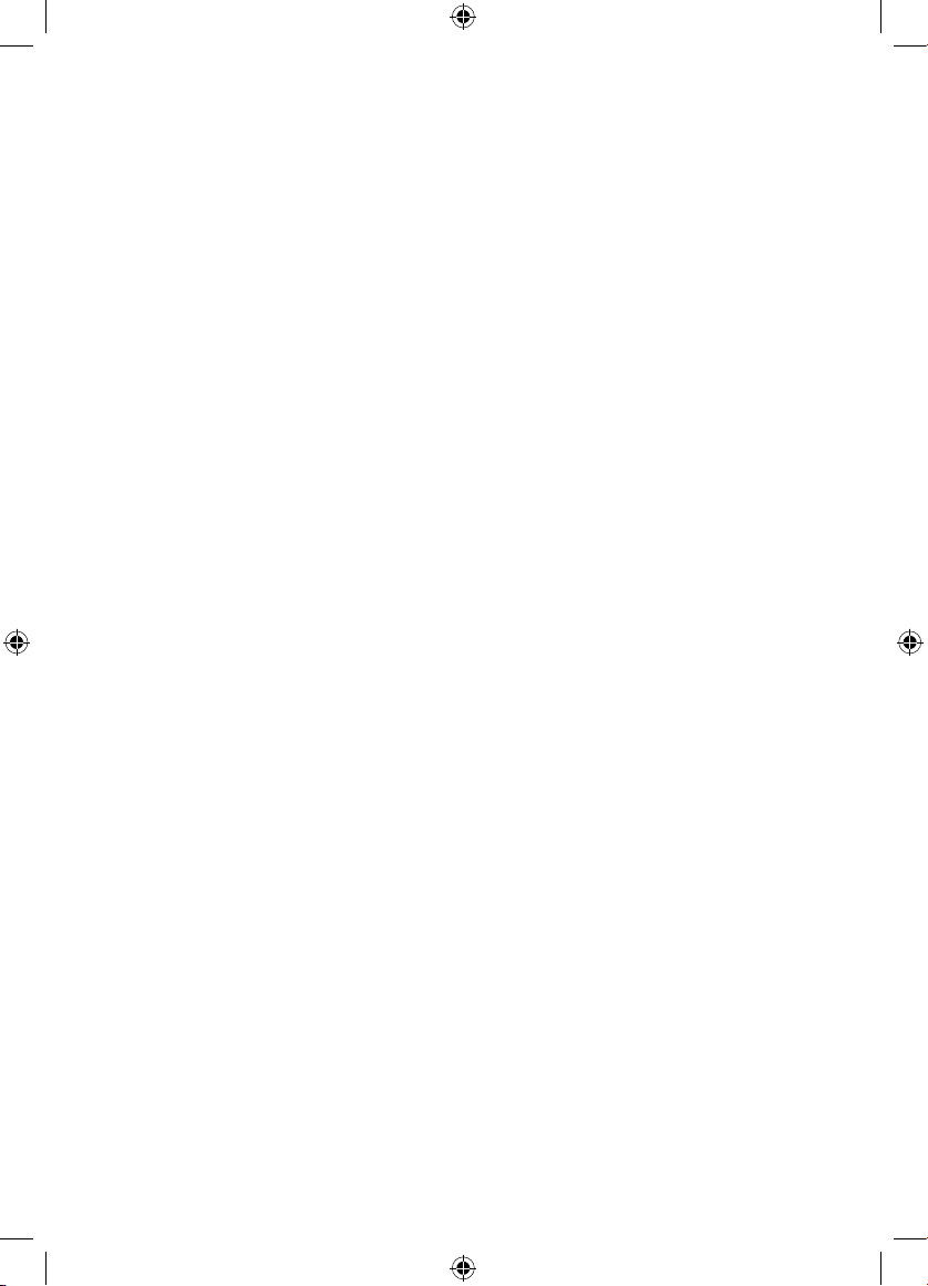
3. The ExpandView™ CAT5
The figures below illustrate the Broadcaster module, Line Splitter, Remote
module and Dual Remote module.
OVERVIEW
Power
Connector
System
Cables
Monitor
ExpandView CAT5
Control Unit
Video Cable
Power
Connector
System
Cables
System cable from Broadcaster or
previus Line Splitter
Broadcaster Module
Linesplitter
P75110ea_F1DV108Aea_QIG.indb 3 25/1/06 9:05:56 am
Page 8
4
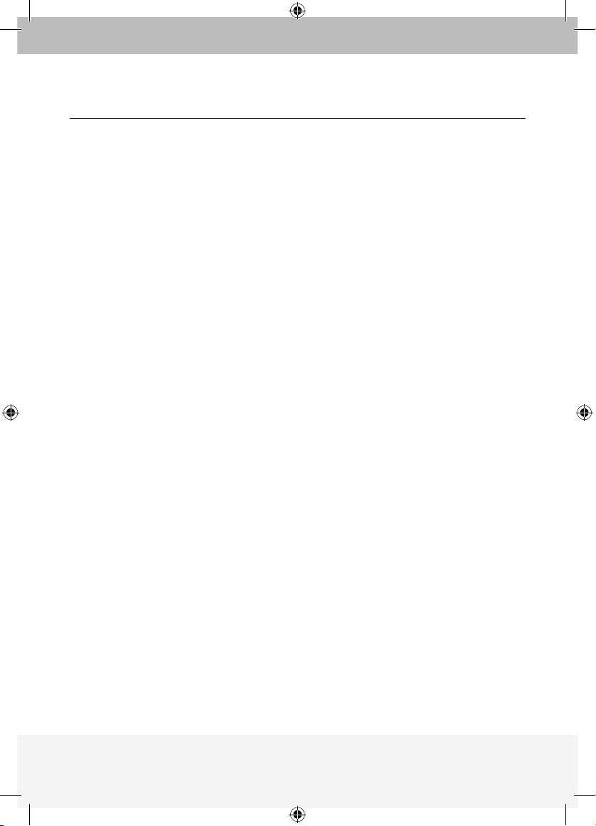
OVERVIEW
Video
Cable
System
Cables
Picture
adjuster
SIDE A SIDE B
To monitors
Dual Remote
Module
To monitors
Remote Module
Dual Remote Module
Monitor
System
Cables
P75110ea_F1DV108Aea_QIG.indb 4 25/1/06 9:05:56 am
Page 9
5
INSTALLATION
4. Expanding the ExpandView™ CAT5
You can expand the ExpandView™ CAT5 to 512 Remote modules by having
2 levels of Line Splitters. Level 1 Line Splitters can have 8 Remote modules or
Line Splitters connected. Level 2 Line Splitters can have 8 Remote modules
connected. (See page 7).
5. Pre-installation instructions
Note! In the ExpandView™ CAT5 the CAT5 UTP or FTP cables carry electrical
power. Therefore do NOT connect them to any other device. Place cables
away from fluorescent lights, air conditioners and machines
that are likely to generate electrical noise.
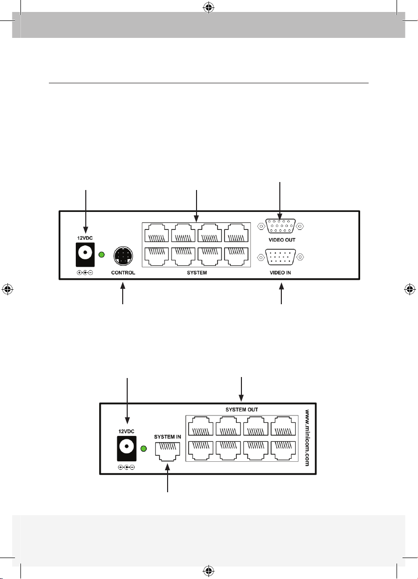
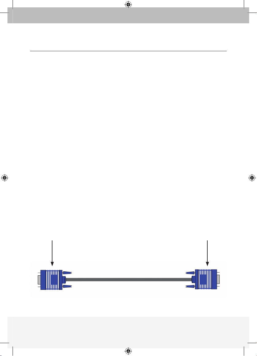
6. The ExpandView™ CAT5 VGA video cables
The Video cable is illustrated below. Connect the cable as explained.
To Computer’s
Video Card
To Broadcaster’s
or Remote’s Video
In port
Broadcaster & Remote Video cable
P75110ea_F1DV108Aea_QIG.indb 5 25/1/06 9:05:57 am
Page 10

6
The Remote Video cable
The Remote Video cable is only used with the Remote module when the
Dongle is connected to a computer.
Connecting the CAT5 cables
Please note! Connect the CAT5 cables to the Broadcaster and Line Splitter
modules when the modules are powered off. We recommend that you
connect the CAT5 cables BEFORE connecting the power supply.
Power supply
Connect the Broadcaster and Line Splitters to the power supply with the
12 VDC, 2A from the AC/DC adapter provided. The Remote modules and
the Dual Remote module receive 12 VDC, 160 mA via the CAT5 cables
from the Broadcaster or Line Splitter.
INSTALLATION
P75110ea_F1DV108Aea_QIG.indb 6 25/1/06 9:05:57 am
Page 11
7
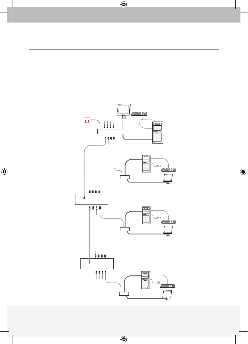
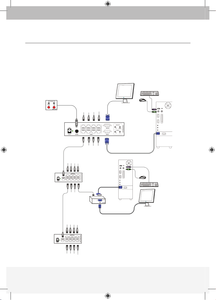
7. The ExpandView™ CAT5 configuration for a Computer Based
Training application
The figure below illustrates the ExpandView™ CAT5 configuration with the
ExpandView
™
CAT5 Control Unit and the optional remote computers.
The Dual Remote module has no VGA input and is therefore not suitable
for CBT applications.
CONFIGURATION
Control
Unit
Broad caster Module
Video cable
Broadcaster
Computer
Remote
Computer
Remote
Computer
Remote
Computer
Video cable
Video cable
Video cable
Remote
modul e
Remote
modul e
Remote
modul e
CAT5 cables
to Remotes or
Line Splitters
CAT5 cables
to Remotes or
Line Splitters
CAT5 cables
to Remotes
CAT5 cables
to Remotes
Level 2
Level
1
Line
Splitter
Line
Splitter
P75110ea_F1DV108Aea_QIG.indb 7 25/1/06 9:05:59 am
Page 12

8
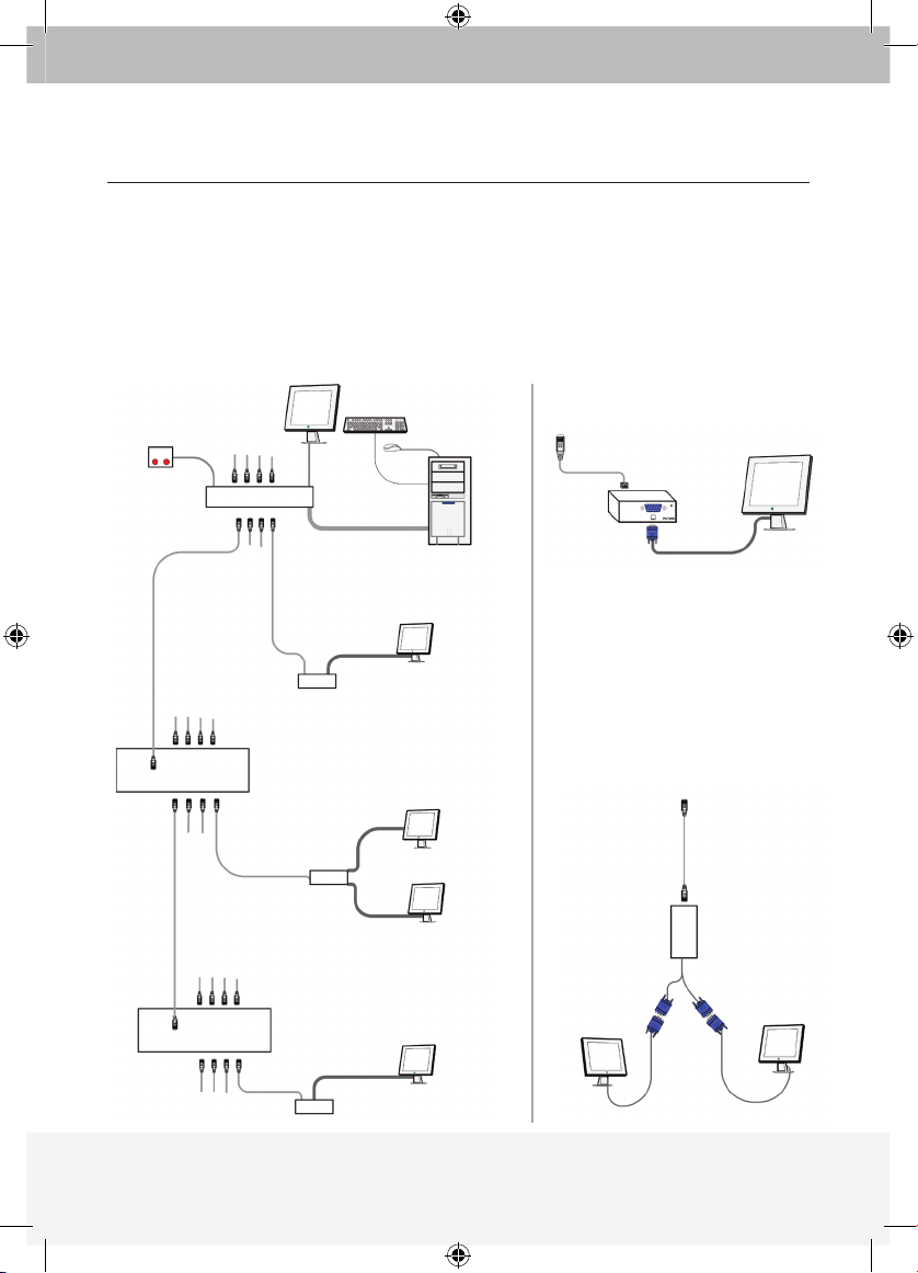
8. ExpandView™ CAT5 detailed connections
The figure below illustrates the detailed connections of the ExpandView™ CAT5.
CONFIGURATION
Control
Unit
Broadcaster
Module
Broadcaster
Computer
Remote
Computer
Video cable
Video cable
Remote
modul e
CAT5 cables
to Remotes or
Line Splitters
CAT5 cables
to Remotes or
Line Splitters
CAT5 cables
to Remotes
CAT5 cables
to Remotes
Line
Splitter
Line
Splitter
CAT5 cables
to Remotes or
Line Splitters
CAT5 cables
to Remotes or
Line Splitters
P75110ea_F1DV108Aea_QIG.indb 8 25/1/06 9:06:03 am
Page 13

9
CAT5 cables to
Broadc aster or
Line Splitters
Dual
Remote
modul e
9. The ExpandView™ CAT5 configuration without remote computers
The figure below illustrates the ExpandView™ CAT5 configuration without
optional computers connected to the Remote modules and the Dual Remote
module. Connect the Broadcaster and Line Splitters as in figure 1.
Figure 2 illustrates the detailed connections of the Remote module.
CONFIGURATION
Broadcaster
Computer
Broad caster Module
Line
Splitter
Line
Splitter
Video cable
Remote
modul e
Dual
Remote
modul e
Remote
modul e
CAT5 cables
to Remotes
CAT5 cables
to Remotes or
Line Splitters
CAT5 cables
to Remotes or
Line Splitters
Control
Unit
Dual Remote Module
Instead of the Remote module,
use the Dual Remote Module
to connect 2 screens to the
Broadcaster or Line Splitter
via CAT5 cable. The 2 screens
display the images broadcast
by the Broadcaster computer.
Remote Module
Remote
modul e
CAT5 cables to Broadcaster
or Line Sp litters
Figur e 1
Figur e
2
Figur e
3
P75110ea_F1DV108Aea_QIG.indb 9 25/1/06 9:06:09 am
Page 14
10
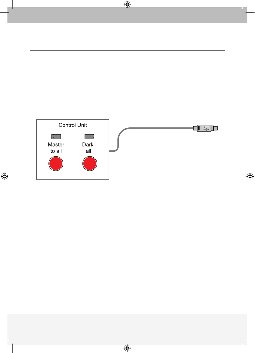
10. Operating the ExpandView™ CAT5
Once connected, the ExpandView™ CAT5 broadcasts to all remote monitors.
The Control Unit
The Control Unit is illustrated below
With the ExpandView
™
CAT5 Control Unit carry out the following functions:
Master to all
Press the Master to all button to send the broadcaster’s screen
to all remote monitors. The LED above the button lights up.
Press the button again to release the remote monitors.
Dark all
Press the Dark all button to darken all remote screens.
The LED above the button lights up.
Press the button again to release the remote screens.
11. Adjusting the picture quality
Use a small screwdriver to turn the Picture adjuster on the Remote module to
adjust the picture quality.
CONFIGURATION
To Broadcaster’s
Control port
P75110ea_F1DV108Aea_QIG.indb 10 25/1/06 9:06:09 am
Page 15
11
SYSTEM
Resolution
Up to 1600x1200 @ 75 Hz
System cable
CAT5 UTP or FTP 2x4x24
AWG Solid Wire Conductor cable
Max distance
110m/360ft
Input/Output Video Signals
Analog signal red, green, blue 0.7v p-p 75 Ohm
Sync.
TTL compatible
Horizontal/Vertical Sync. Polarity
Positive/Negative
Operating temperature
0ºC to 40ºC/32ºF to 104ºF
Storage temperature
-40ºC to 70ºC/-40ºC to 158ºF
Humidity
80% non condensing relative humidity
Warranty
3 Years
BROADCASTER
MODULE
LINE SPLITTER REMOTE MODULE
Cables & Connectors
VGA In - HDD15M System In - RJ45 System In - RJ45
VGA Out - HDD15F System Out - RJ45 CPU VGA - HDD15M
System Out - 8 Ports
RJ45
Screen - HDD15F
Control - MiniDin8F
Dimensions
175 x 96 x 42mm/
0.57 x 0.38 x 0.14ft
118 x 96 x 42mm/
0.39 x 0.38 x 0.14ft
78 x 62 x 23mm/ 0.31
x 0.26 x 0.07ft
Power supply
External Power
Adapter 12VDC 2A
External Power
Adapter 12VDC 2A
From previous unit
through CAT5 cable
DUAL REMOTE MODULE
Cables
& Connectors
System In - RJ45
Screen x 2 - HDD15F
Power
supply
From previous unit
through CAT5 cable
TECHNICAL SPECIFICATIONS
P75110ea_F1DV108Aea_QIG.indb 11 25/1/06 9:06:09 am
Page 16

P75110ea
© 2006 Belkin Corporation. All rights reserved. All trade names
are registered trademarks of respective manufacturers listed.
Belkin Ltd.
Express Business Park
Shipton Way, Rushden
NN10 6GL, United Kingdom
+44 (0) 1933 35 2000
+44 (0) 1933 31 2000 fax
Belkin B.V.
Boeing Avenue 333
1119 PH Schiphol-Rijk
The Netherlands
+31 (0) 20 654 7300
+31 (0) 20 654 7349 fax
Belkin GmbH
Hanebergstraße 2
80637 Munich
Germany
+49 (0) 89 143405 0
+49 (0) 89 143405 100 fax
Belkin SAS
130 rue de Silly
92100 Boulogne-Billancourt
France
+33 (0) 1 41 03 14 40
+33 (0) 1 41 31 01 72 fax
Belkin Nordic
Knarrarnäsgatan 7
164 40 Kista
Sweden
+46 (0) 8 5229 1870
+46 (0) 8 5229 1874 fax
Belkin Iberia
Avda. Cerro del Aguila 3
28700 San Sebastián de los Reyes
Spain
+34 (0) 9 16 25 80 00
+34 (0) 9 02 02 00 34 fax
Belkin Tech Support
Europe: 00 800 223 55 460
ExpandView™ CAT5
P75110ea_F1DV108Aea_QIG.indb 12 25/1/06 9:06:10 am
Page 17

ExpandView™ CAT5
Guide d’Installation Rapide
F1DV108Aea
Fr
P75110ea_F1DV108Aea_QIG.indb 13 25/1/06 9:06:12 am
Page 18

Introduction
1. Qu’est-ce que l’ExpandView
™
CAT5 ? ..................................................... 1
Présentation
2. L’ExpandView
™
CAT5 multifonctions ........................................................ 2
3. L’ExpandView
™
CAT5 ................................................................................ 3
Installation
4. Déploiement de l’ExpandView
™
CAT5 ...................................................... 5
5. Instructions de pré-installation .................................................................
5
6. Les câbles de l’ExpandView
™
CAT5 ......................................................... 5
Le câble Écran distant ..............................................................................
6
Branchement des câbles CAT5 ................................................................
6
Alimentation ..............................................................................................
6
Configuration
7. Configuration de l’ExpandView™ CAT5 pour l’utilisation en FAO
(Formation Assistée par Ordinateur) .........................................................
7
8. Détail des branchements de l’ExpandView
™
CAT5 .................................. 8
9. Configuration de l’ExpandView
™
CAT5 sans ordinateurs distants ........... 9
10. Déploiement de l’ExpandView
™
CAT5 .................................................... 10
Caractéristiques techniques
Caractéristiques techniques ............................................................................
11
TABLE DES MATIÈRES
P75110ea_F1DV108Aea_QIG.indb 14 25/1/06 9:06:12 am
Page 19

1
1. Qu’est-ce que l’ExpandView™ CAT5 ?
L’ExpandView™ CAT5 de Belkin émet des signaux vidéo haute-résolution, en
temps réel, vers des centaines d’écrans distants.
L’ExpandView
™
CAT5 comprend :
• Un Émetteur + une Unité de contrôle
• Des Séparateurs de ligne pour déployer le système
• Un Module distant qui connecte chacun des moniteurs/ordinateurs distants
• Un Module distant double qui connecte deux moniteurs au système
Des câbles UTP ou FTP CAT5 relient l’ExpandView
™
CAT5.
Les Unités distantes peuvent se trouver jusqu’à 110 m/360 pi de l’Émetteur.
Ce Guide d’installation rapide vous décrit l’ExpandView
™
CAT5
et vous explique comment l’installer et le faire fonctionner.
INTRODUCTION
P75110ea_F1DV108Aea_QIG.indb 1 25/1/06 9:06:12 am
Page 20

2
2. L’ExpandView™ CAT5 multifonctions
Vous pouvez utiliser l’ExpandView™ CAT5 de plusieurs façons :
(A) Sans l’Unité de contrôle
L’ExpandView
™
CAT5 envoie en permanence un affichage d’écran à tous les
moniteurs distants.
(B) Avec l’Unité de contrôle
• Pour envoyer un affichage d’écran à tous les moniteurs distants
• Pour assombrir tous les écrans distants
• Pour libérer tous les écrans distants et leur permettre d’afficher l’écran local
(lorsque les ordinateurs distants sont connectés).
La fonctionnalité d’écran noir s’avère très utile pour les opérations de
maintenance, la modification du programme d’émission ou pour capter
l’attention des élèves en environnement éducatif.
Dans les deux contextes, vous émettez de la vidéo à une résolution pouvant
aller jusqu’à 1 600 x 1 200 à 75 Hz, en fonction de la longueur du câble.
PRÉSENTATION
P75110ea_F1DV108Aea_QIG.indb 2 25/1/06 9:06:12 am
Page 21

3
3. L’ExpandView™ CAT5
Les schémas ci-dessous représentent le module Émetteur, le Séparateur de
ligne, le Module distant et le Module distant double.
PRÉSENTATION
Prise
alimentation
Câbles
système
Moniteur
Unité de contrôle
ExpandViewCAT5
Câble vidéo
Prise
alimentation
Câbles
système
Câble système de l’Émetteur ou
Séparateur de ligne précédent
Module émetteur
Séparateur de ligne
P75110ea_F1DV108Aea_QIG.indb 3 25/1/06 9:06:13 am
Page 22

4
PRÉSENTATION
Câble
vidéo
Câbles
système
Régulateur
d’image
FACE A FACE B
Sur les moniteurs
Module distant
double
Sur les moniteurs
Module distant
Module distant double
Moniteur
Câbles
système
P75110ea_F1DV108Aea_QIG.indb 4 25/1/06 9:06:13 am
Page 23

5
INSTALLATION
4. Déploiement de l’ExpandView™ CAT5
Vous pouvez déployer l’ExpandView™ CAT5 sur 512 Modules distants avec
2 niveaux de Séparateurs de ligne. Les Séparateurs de ligne de niveau
1 peuvent connecter 8 Modules distants ou Séparateurs de ligne. Les
Séparateurs de ligne de niveau 2 peuvent connecter 8 Modules distants. (voir
page 7).
5. Instructions de pré-installation
Remarque ! Les câbles UTP et FTP CAT5 de l’ExpandView™CAT5 conduisent
de l’électricité. En conséquence, ne les branchez jamais à un autre appareil.
Maintenez les câbles à distance des tubes fluorescents, climatisations et
autres appareils susceptibles de créer des interférences électriques.
6. Les câbles vidéo VGA de l’ExpandView
™
Le câble vidéo est représenté ci-dessous. Branchez-le comme indiqué.
Sur carte graphique
de l’ordinateur
Sur port d’entrée
de l’Émetteur ou
Écran distant
Câble Émetteur et Écran distant
P75110ea_F1DV108Aea_QIG.indb 5 25/1/06 9:06:14 am
Page 24

6
Le câble Écran distant
Le câble d’écran distant n’est utilisé avec le Module distant que lorsque
l’adaptateur est branché à un ordinateur.
Branchement des câbles CAT5
Attention ! Branchez les câbles CAT5 aux modules Émetteur et Sépateur
de ligne lorsqu’ils sont éteints. Nous vous recommandons de brancher les
câbles CAT5 avant de brancher l’alimentation.
Alimentation
Branchez l’Émetteur et les Séparateurs de ligne sur l’alimentation VCC 2 A
de l’adaptateur CA/CC fourni. Les Modules distants et le Module distant
double reçoivent 12 VCC 160 mA par les câbles CAT5 de l’Émetteur ou
Séparateur de ligne.
INSTALLATION
P75110ea_F1DV108Aea_QIG.indb 6 25/1/06 9:06:14 am
Page 25

7
7. Configuration de l’ExpandView™ CAT5 pour l’utilisation en FAO
(Formation Assistée par Ordinateur)
Le schéma ci-dessous représente la configuration de l’ExpandView™ CAT5
avec l’Unité de contrôle ExpandView
™
CAT5 et les ordinateurs distants
facultatifs. Le Module distant double n’a pas d’entrée VGA et ne convient
donc pas aux applications de FAO.
CONFIGURATION
Unité de
contrôle
Modul e émetteur
Câble vidéo
Ordinateur
émetteur
Ordinateur
distant
Ordinateur
distant
Ordinateur
distant
Câble vidéo
Câble vidéo
Câble vidéo
Modul e
distant
Modul e
distant
Modul e
distant
Câbles CAT5 su r
Module s distants
ou Sépar ateurs
de ligne
Câbles CAT5 su r
Module s distants
ou Sépar ateurs
de ligne
Câbles CAT5 su r
Module s distants
Câbles CAT5 su r
Module s distants
Niveau 2
Niveau
1
Séparateur
de ligne
Séparateur
de ligne
P75110ea_F1DV108Aea_QIG.indb 7 25/1/06 9:06:16 am
Page 26
8
8. Détail des branchements de l’ExpandView™ CAT5
Le schéma ci-dessous représente en détails les branchements de
l’ExpandView
™
CAT5.
CONFIGURATION
Unité de
contrôle
Module
émetteur
Ordinateur
émetteur
Ordinateur
distant
Câble vidéo
Câble vidéo
Modul e
distant
Câbles CAT5 su r
Module s distants ou
Séparateurs de l igne
Câbles CAT5 su r
Module s distants
ou Sépar ateurs
de ligne
Câbles CAT5 su r
Module s distants
Câbles CAT5 su r
Module s distants
Séparateur
de ligne
Séparateur
de ligne
Câbles CAT5 su r
Module s distants
ou Sépar ateurs
de ligne
Câbles CAT5 su r
Module s distants ou
Séparateurs de l igne
P75110ea_F1DV108Aea_QIG.indb 8 25/1/06 9:06:20 am
Page 27
9
Câbles CAT5
sur Émet teur
ou Sépar ateurs
de ligne
Modul e
distant
doubl e
9. Configuration de l’ExpandView™ CAT5 sans ordinateurs distants
Le schéma ci-dessous représente la configuration de l’ExpandView™ CAT5 sans
ordinateurs facultatifs branchés sur les Modules distants et le Module distant
double. Connectez l’Émetteur et les Séparateurs de ligne suivant le schéma 1.
Le schéma 2 représente en détails les branchement du Module distant.
CONFIGURATION
Ordinateur
émetteur
Modul e émetteur
Séparateur
de ligne
Séparateur
de ligne
Câble vidéo
Modul e
distant
Modul e
distant
doubl e
Modul e
distant
Câbles CAT5 su r
Module s distants
Câbles CAT5 su r
Module s distants
ou Sépar ateurs
de ligne
Câbles CAT5 sur
Modules distants
ou Séparateur s
de ligne
Unité de
contrôle
Module distant double
Pour relier deux écrans à l’Émetteur
ou au Séparateur de ligne avec
un câble CAT5, utilisez le Module
distant double plutôt qu’un
Module distant. Les deux écrans
affichent alors les images envoyées
par l’ordinateur émetteur.
Module distant
Modul e
distant
Câbles CAT5 su r Émetteur
ou Sépar ateurs de ligne
Schém a 1
Schém a
2
Schém a
3
P75110ea_F1DV108Aea_QIG.indb 9 25/1/06 9:06:26 am
Page 28

10
10. Utilisation de l’ExpandView™ CAT5
Une fois connecté, l’ExpandView™ CAT5 émet vers tous les moniteurs distants.
L’Unité de contrôle
L’Unité de contrôle est représentée ci-dessous.
Elle permet de réaliser les fonctions suivantes :
Master to all (Tout contrôler)
Appuyez sur le bouton Master to all (Tout contrôler) pour
envoyer l’écran de l’Émetteur vers tous les moniteurs distants.
Le témoin au-dessus du bouton s’allume alors.
Appuyez de nouveau sur le bouton pour libérer les moniteurs distants.
Dark all (Tout obscurcir)
Appuyez sur le bouton Dark all (Tout obscurcir) pour noircir tous les
écrans distants. Le témoin au-dessus du bouton s’allume alors.
Appuyez de nouveau sur le bouton pour libérer les écrans distants.
11. Réglage de la qualité d’image
Utilisez un petit tournevis pour tourner le régulateur sur le Module
distant et ainsi régler la qualité de l’image.
CONFIGURATION
Sur port de
contrôle de
l’émetteur
P75110ea_F1DV108Aea_QIG.indb 10 25/1/06 9:06:26 am
Page 29

11
SYSTÈME
Résolution
Jusqu’à 1 600 x 1 200 à 75 Hz
Câble système
Câble à conducteur solide calibre 2x4x24
UTP ou FTP CAT5
Distance maxi
110 m/360 pi
Signal vidéo entrée/sortie
Signal analogique rouge, vert, bleu 0,7 V crête à crête
75 Ohm
Sync.
Compatible TTL
Synchronisation horizontale/verticale
Polarité
Positif/Négatif
Température de fonctionnement
de 0ºC à 40ºC / 32ºF à 104ºF
Température de stockage
-40ºC à 70ºC / -40ºF à 158ºF
Humidité
80 % d’humidité relative (sans
condensation)
Garantie
3 ans
MODULE
ÉMETTEUR
SÉPARATEUR DE
LIGNE
MODULE DISTANT
Câbles et
connecteurs
Entrée VGA HDD15M
Entrée système RJ45
Entrée système RJ45
Sortie VGA - HDD15F Sortie système - RJ45 VGA UC - HDD15M
Sortie système- 8
ports RJ45
Écran - HDD15F
Contrôle - MiniDin8F
Dimensions
175 x 96 x 42 mm/
0,57 x 0,38 x 0,14 pi
118 x 96 x 42 mm/
0,39 x 0,38 x 0,14 pi
78 x 62 x 23 mm/ 0,31
x 0,26 x 0,07 pi
Alimentation
Adaptateur externe
12 VCC 2A
Adaptateur externe
12 VCC 2A
De l’unité précédente
via un câble CAT5
MODULE DISTANT DOUBLE
Câbles
et branchements
Entrée système RJ45
Écran x 2 - HDD15F
Alimentation
De l’unité précédente
via un câble CAT5
CARACTÉRISTIQUES TECHNIQUES
P75110ea_F1DV108Aea_QIG.indb 11 25/1/06 9:06:26 am
Page 30

P75110ea
© 2006 Belkin Corporation. Tous droits réservés. Toutes les raisons commerciales
sont des marques déposées de leurs fabricants respectifs.
Belkin Ltd.
Express Business Park
Shipton Way, Rushden
NN10 6GL, Royaume-Uni
+44 (0) 1933 35 2000
+44 (0) 1933 31 2000 Fax
Belkin B.V.
Boeing Avenue 333
1119 PH Schiphol-Rijk
Pays-Bas
+31 (0) 20 654 7300
+31 (0) 20 654 7349 Fax
Belkin GmbH
Hanebergstraße 2
80637 Munich
Allemagne
+49 (0) 89 143405 0
+49 (0) 89 143405 100 Fax
Belkin SAS
130 rue de Silly
92100 Boulogne-Billancourt
France
+33 (0) 1 41 03 14 40
+33 (0) 1 41 31 01 72 Fax
Belkin Nordic
Knarrarnäsgatan 7
164 40 Kista
Suède
+46 (0) 8 5229 1870
+46 (0) 8 5229 1874 Fax
Belkin Iberia
Avda Cerro del Aguila 3
28700 San Sebastián de los Reyes
Espagne
+34 (0) 9 16 25 80 00
+34 (0) 9 02 02 00 34 fax
Assistance technique Belkin
Europe : 00 800 223 55 460
ExpandView™ CAT5
P75110ea_F1DV108Aea_QIG.indb 12 25/1/06 9:06:27 am
Page 31

ExpandView™ CAT5
Installationsanleitung
F1DV108Aea
De
P75110ea_F1DV108Aea_QIG.indb 13 25/1/06 9:06:29 am
Page 32

Einleitung
1. Was ist der ExpandView
™
CAT5? ............................................................. 1
Übersicht
2. Die vielen Funktionen des ExpandView
™
CAT5? ...................................... 2
3. Der ExpandView
™
CAT5? .......................................................................... 3
Installation
4. Erweiterung des ExpandView
™
CAT5? ..................................................... 5
5. Vorbereitung des Geräts ...........................................................................
5
6. Die Kabel für den ExpandView
™
CAT5? ................................................... 5
Das Fernsteuerungs-Grafikkabel ..............................................................
6
Anschließen der CAT5-Kabel ...................................................................
6
Netzteil ......................................................................................................
6
Konfiguration
7. Die Einstellung des ExpandView
™
CAT5 für CBT-Anwendungen ............. 7
8. Die Anschlüsse des ExpandView
™
CAT5 .................................................. 8
9. Die Einstellung des ExpandView
™
CAT5
ohne Fernsteuerungs-Computer ..............................................................
9
10. Bedienung des ExpandView
™
CAT5 ....................................................... 10
Technische Daten
Technische Daten .......................................................................................
11
INHALTSVERZEICHNIS
P75110ea_F1DV108Aea_QIG.indb 14 25/1/06 9:06:29 am
Page 33

1
1. Was ist der ExpandView™ CAT5?
Der ExpandView™ CAT5 von Belkin sendet hochauflösende
Echtzeit-Grafiksignale an hunderte entfernte Monitore.
Der ExpandView
™
CAT5 besteht aus folgenden Komponenten:
• Sender + Kontrolleinheit
• Leitungs-Splitter zur Erweiterung des Systems
• Fernsteuerungsmodul für die Verbindung mit jedem
entfernten Monitor/Computer
• Dual-Fernsteuerungseinheit für die Verbindung
von 2 Monitoren mit dem System
CAT5 UTP- oder FTP-Kabel für die Verbindung mit dem ExpandView
™
CAT5.
Die Fernsteuerungseinheiten können bis zu 110m vom der Sendeeinheit
entfernt stehen.
In dieser Installationsanleitung wird der ExpandView
™
CAT5
beschrieben und es wird erläutert, wie Sie diesen installieren und bedienen.
EINLEITUNG
P75110ea_F1DV108Aea_QIG.indb 1 25/1/06 9:06:29 am
Page 34

2
2. Die vielen Funktionen des ExpandView™ CAT5
Sie können den ExpandView™ CAT5 folgendermaßen einsetzen:
(A) Ohne die Kontrolleinheit
sendet der ExpandView
™
CAT5 ununterbrochen eine
Monitoranzeige an alle Fernesteuerungscomputer.
(B) Mit der Kontrolleinheit
• Sendet eine Monitoranzeige an alle Fernsteuerungsmonitore
• Verdunkelt alle Fernsteuerungsmonitore
• Gibt die Fernsteuerungsmonitore frei, so das diese lokal betrachtet werden
können (wenn Fernesteuerungscomputer angeschlossen sind).
Die verdunkelte Anzeige ist bei Wartungsarbeiten, Änderung des
Sendeprogramms oder in einem Unterrichtsraum zur Wiedererlangung der
Aufmerksamkeit der Schüler nützlich.
Mit beiden Anwendungen werden Grafiksignale mit einer Auflösung bis zu
1600 x 1200 / 75 Hz gesendet, abhängig von der Kabellänge.
ÜBERSICHT
P75110ea_F1DV108Aea_QIG.indb 2 25/1/06 9:06:29 am
Page 35

3
3. Der ExpandView™ CAT5
In den Abbildungen werden Sendemodul, Leitungs-Splitter,
Fernsteuerungsmodus und Dual-Fernsteuerungsmodus gezeigt.
ÜBERSICHT
Netzanschluss System-Kabel Monitor
ExpandView CAT5
Kontroll-Einheit
Grafikkabel
Netzanschluss System-Kabel
System-Kabel vom Sender oder vorhergehenden
Leitungs-Splittern
Sender-Modul
Leitungs-Splitter
P75110ea_F1DV108Aea_QIG.indb 3 25/1/06 9:06:30 am
Page 36

4
ÜBERSICHT
Grafikkabel System-Kabel Bild-Korrektur
SEITE A SEITE B
An Monitore
Fernsteuerungsmodul
An Monitore
Fernsteuerungsmodul
Dual-Fernsteuerungsmodul
Monitor
System-Kabel
P75110ea_F1DV108Aea_QIG.indb 4 25/1/06 9:06:30 am
Page 37

5
INSTALLATION
4. Erweiterung des ExpandView™ CAT5
Sie können den ExpandView™ CAT5 auf 512 Fernsteuerungsmodule
erweitern, wenn Sie 2 Ebenen mit Leitungs-Splittern einrichten. LeitungsSplitter in der Ebene 1 können mit 8 Fernsteuerungsmodulen oder LeitungsSplittern verbunden werden. Leitungs-Splitter in der Ebene 2 können mit 8
Fernsteuerungsmodulen verbunden werden (Siehe Seite 7).
5. Vorbereitung des Geräts
Hinweis! Im ExpandView™ CAT5 sind die CAT5 UTP- oder FTP-Kabel
stromführend. Verbinden Sie diese daher
NICHT mit anderen Geräten. Setzen
Sie die Kabel keinem fluoreszierenden Licht, keinen Klimaanlagen und
Maschinen aus, die elektrisches Rauschen verursachen.
6. Die ExpandView™ CAT5 VGA-Grafikkabel
Das Grafikkabel ist unten abgebildet. Verbinden Sie das Kabel wie
beschrieben.
An die Grafikkarte
des Computers
An den Grafik-Eingang
des Senders oder des
Fernsteuerungs-Monitors
Das Sender- & Fernsteuerungs-Grafikkabel
P75110ea_F1DV108Aea_QIG.indb 5 25/1/06 9:06:31 am
Page 38

6
Das Fernsteuerungs-Grafikkabel
Das Fernsteuerungs-Grafikkabel wird nur mit dem Fernsteuerungsmodul
verwendet, wenn der Dongle an einen Computer angeschlossen ist.
Anschließen der CAT5-Kabel
Hinweis! Verbinden Sie die CAT5-Kabel mit dem Sender und dem
Leitungs-Splitter, wenn die Geräte ausgeschaltet sind. Wir empfehlen,
die CAT5-Kabel anzuschließen, BEVOR Sie die Geräte an das Stromnetz
anschließen.
Netzteil
Verbinden Sie den Sender und den Leitungs-Splitter mit der
Stromversorgung über den 12 VDC, 2A-Anschluss des mitgelieferten
Adapters. Die Fernsteuerungsmodule und das Dual-Fernsteuerungsmodul
empfangen 12 VDC, 160 mA über das CAT5-Kabel des Senders oder
Leitungs-Splitters.
INSTALLATION
P75110ea_F1DV108Aea_QIG.indb 6 25/1/06 9:06:31 am
Page 39

7
7. Die Einstellung des ExpandView™ CAT5 für eine CBTAnwendung (Computer-Lernprogramm)
In der Abbildung unten wird die Einrichtung des ExpandView™ CAT5 mit
der ExpandView™ CAT5-Kontrolleinheit und die optionalen FernsteuerungsComputer angzeigt. Das Dual-Fernsteuerungsmodul hat keinen VGA-Eingang
und ist daher nicht für CBT-Anwendungen geeignet.
KONFIGURATION
Kontroll-
Einheit
Sender-Mod ul
Grafik kabel
Sender-
Computer
Fernsteuerungs-
Computer
Fernsteuerungs-
Computer
Fernsteuerungs-
Computer
Grafik kabel
Grafik kabel
Grafik kabel
Ferns teuerungs
modul
Ferns teuerungs
modul
Ferns teuerungs
modul
CAT5-Kabe l an
Fernste uerungsoder Lei tungsSplitter
CAT5-Kabe l an
Fernste uerungs-
oder Lei tungs-
Splitter
CAT5-Kabe l an
Fernste uerungs-
Einheiten
CAT5-Kabe l an
Fernste uerungs-
Einheiten
Ebene 2
Ebene
1
Leitungs-
Splitter
Leitungs-
Splitter
P75110ea_F1DV108Aea_QIG.indb 7 25/1/06 9:06:33 am
Page 40

8
8. Die Anschlüsse des ExpandView™ CAT5
In dieser Abbildung sind die Anschlüsse des ExpandView™ CAT5wiedergegeben.
KONFIGURATION
Kontroll-
Einheit
Sender-
Modul
Sender-
Computer
Fernsteuerungs-
Computer
Grafik kabel
Grafik kabel
Ferns teuerungs
modul
CAT5-Kabe l an
Fernste uerungs- ode r
Leitungs-Spl itter
CAT5-Kabe l an
Fernste uerungs-
oder Lei tungs-
Splitter
CAT5-Kabe l an
Fernste uerungs-
Einheiten
CAT5-Kabe l an
Fernste uerungs-
Einheiten
Leitungs-
Splitter
Leitungs-
Splitter
CAT5-Kabe l an
Fernste uerungs-
oder Lei tungs-
Splitter
CAT5-Kabe l an
Fernste uerungs- ode r
Leitungs-Spl itter
P75110ea_F1DV108Aea_QIG.indb 8 25/1/06 9:06:37 am
Page 41

9
Ferns teuerungs
modul
CAT5-Kabe l an Senderoder Lei tungs-Split ter
CAT5-Kabe l an
Sender- oder
Leitungs-Spl itter
DualFerns teuerungs
modul
9. Die Einstellung des ExpandView™ CAT5 ohne
Fernsteuerungs-Computer
In dieser Abbildung wird die Einstellung des ExpandView™ CAT5 ohne optionale
Computer dargestellt, die mit den Fernsteuerungsmodulen und dem DualFernsteuerungsmodul verbunden werden können. Verbinden Sie den Sender und die
Leitungs-Splitter wie in Abbildung 1 dargestellt. In Abbildung 2 sind die Anschlüsse des
Fernsteuerungsmoduls wiedergegeben.
KONFIGURATION
Sender-
Computer
Sender-Mod ul
Leitungs-
Splitter
Leitungs-
Splitter
Grafik kabel
Ferns teuerungs
modul
Ferns teuerungs
modul
CAT5-Kabe l an
Fernste uerungs-
Einheiten
CAT5-Kabe l an
Fernste uerungs-
oder Lei tungs-
Splitter
CAT5-Kabe l an
Fernste uerungs-
oder Lei tungs-
Splitter
Kontroll-
Einheit
Dual-Fernsteuerungsmodul
Anstelle des
Fernsteuerungsmoduls
verwenden Sie das DualFernsteuerungsmodul, um 2
Monitore mit dem Sender oder
dem Leitungs-Splitter mit einem
CAT5-Kabel zu verbinden Auf den
2 Monitoren wird der Bildschirm
des Sender-Computers angezeigt.
Fernsteuerungs-Modul
Abbildung 1
Abbildung
2
Abbildung 3
Ferns teuerungs
modul
P75110ea_F1DV108Aea_QIG.indb 9 25/1/06 9:06:43 am
Page 42

10
10. Bedienung des ExpandView™ CAT5
Nach der Verbindung sendet der ExpandView™ CAT5 an alle FernsteuerungsMonitore.
Die Kontrolleinheit
Die Kontrolleinheit ist unten abgebildet
Mit dem ExpandView
™
CAT5 kann die Kontrolleinheit
folgende Funktionen ausüben:
Master für alle
Drücken auf den Schaltknopf Master to all (Master für alle), um
die Monitoranzeige des Senders an alle Fernsteuerungsmonitore
zu senden. Die LED-Anzeige über dem Schaltknopf leuchtet.
Drücken Sie den Schaltknopf erneut, um die
Fernsteuerungsmonitore freizugeben.
Alle verdunkeln
Drücken Sie auf den SchaltknopfDark all (Alle verdunkeln)
,
um alle Fernsteuerungsmonitore zu verdunkeln. Die LEDAnzeige über dem Schaltknopf leuchtet.
Drücken Sie den Schaltknopf erneut, um die
Fernsteuerungsmonitore freizugeben.
11. Einstellung der Bildqualität
Sie können die Bildkorrektur am Fernsteuerungsmodul mit einem schmalen
Schraubendreher einstellen, um die Bildqualität anzupassen.
KONFIGURATION
An den Kontroll-
Port des Senders
P75110ea_F1DV108Aea_QIG.indb 10 25/1/06 9:06:43 am
Page 43

11
SYSTEM
Auflösung
Max. 1600x1200 / 75 Hz
Systemkabel
CAT5 UTP- oder FTP 2x4x24 AWG-Massivleiterkabel
Maximaler Abstand
110 m
Eingangs-/Ausgangs-Grafiksignale
Analoges Signal rot, grün, blau 0,7v p-p 75 Ohm
Sync.
TTL-Kompatibel
Horizontal-/Vertikal-Sync. Polarität
Positiv/Negativ
Betriebstemperatur
0ºC bis 40ºC
Lagertemperatur
-40ºC bis 70ºC
Relative Luftfeuchtigkeit
80%relative Luftfeuchtigkeit (nicht kondensierend)
Garantie
3 Jahre
SENDER-MODUL LEITUNGS-
SPLITTER
FERNSTEUERUNGS-
MODUL
Kabel & Anschlüsse
VGA-Eingang HDD15M
SystemEingang - RJ45
System-
Eingang - RJ45
VGA-Ausgang HDD15F
SystemEingang - RJ45
CPU VGA -
HDD15-Stecker
System-Ausgang 8 Ports RJ45
Monitor -
HDD15-Buchse
Kontrolle - 8pol.
MiniDin-Buchse
Abmessungen
175 x 96 x 42 mm
118 x 96 x 42 mm 78 x 62 x 23 mm
Netzteil
Externer Netzadapter
12 VDC 2A
Externer Netzadapter
12VDC 2A
Von vorhergehender
Einheit über
wCAT5-Kabel
DUAL- FERNSTEUERUNGSMODUL
Kabel & Anschlüsse
System-Eingang
- RJ45
Monitor x 2 HDD15-Buchse
Netzteil
Von vorhergehender
Einheit über
CAT5-Kabel
TECHNISCHE SPEZIFIKATIONEN
P75110ea_F1DV108Aea_QIG.indb 11 25/1/06 9:06:43 am
Page 44

P75110ea
© 2006 Belkin Corporation Alle Rechte vorbehalten. Alle Produktnamen
sind eingetragene Marken der angegebenen Hersteller.
Belkin Ltd.
Express Business Park
Shipton Way, Rushden
NN10 6GL, Großbritannien
+44 (0) 1933 35 2000
+44 (0) 1933 31 2000 Fax
Belkin B.V.
Boeing Avenue 333
1119 PH Schiphol-Rijk
Niederlande
+31 (0) 20 654 7300
+31 (0) 20 654 7349 Fax
Belkin GmbH
Hanebergstraße 2
80637 München
Deutschland
+49 (0) 89 143405 0
+49 (0) 89 143405 100 Fax
Belkin SAS
130 rue de Silly
92100 Boulogne-Billancourt
Frankreich
+33 (0) 1 41 03 14 40
+33 (0) 1 41 31 01 72 Fax
Belkin Nordic
Knarrarnäsgatan 7
164 40 Kista
Schweden
+46 (0) 8 5229 1870
+46 (0) 8 5229 1874 Fax
Belkin Iberia
Avda. Cerro del Aguila 3
28700 San Sebastián de los Reyes
Spanien
+34 (0) 9 16 25 80 00
+34 (0) 9 02 02 00 34 Fax
Belkin Technischer Support
Europa: 00 800 223 55 460
ExpandView™ CAT5
P75110ea_F1DV108Aea_QIG.indb 12 25/1/06 9:06:44 am
Page 45

ExpandView™ CAT5
Beknopte installatiehandleiding
F1DV108Aea
Nl
P75110ea_F1DV108Aea_QIG.indb 13 25/1/06 9:06:46 am
Page 46

Inleiding
1. Wat is de ExpandView
™
CAT5? ................................................................ 1
Overzicht
2. De multifunctionele ExpandView
™
CAT5 .................................................. 2
3. De ExpandView
™
CAT5 ............................................................................. 3
Installatie
4. Uibreiding van de ExpandView
™
CAT5 ..................................................... 5
5. Voorbereiding op de installatie .................................................................
5
6. De ExpandView
™
CAT5-kabels ................................................................. 5
De remote-videokabel ..............................................................................
6
De CAT5-kabels aansluiten ......................................................................
6
Voeding .....................................................................................................
6
Configuratie
7. De ExpandView
™
CAT5-configuratie voor een CBT-applicatie ................. 7
8. Gedetailleerd overzicht van de ExpandView
™
CAT5 verbindingen .......... 8
9. De ExpandView
™
CAT5-configuratie zonder remote computers .............. 9
10. Gebruik maken van de ExpandView
™
CAT5 ..........................................10
Technische gegevens
Technische gegevens .......................................................................................
11
INHOUD
P75110ea_F1DV108Aea_QIG.indb 14 25/1/06 9:06:46 am
Page 47

1
1. Wat is de ExpandView™ CAT5?
De ExpandView™ CAT5 van Belkin verzend real-time hogeresolutie-videosignalen
naar honderden remote display monitoren.
De ExpandView
™
CAT5 omvat het volgende:
• Zender + beheereenheid
• Lijnsplitters voor uitbreiding van het systeem
• Remote module voor verbinding met elke remote monitor/computer
• Tweevoudige remote module voor aansluiting van 2 monitoren op het systeem
CAT5 UTP- of FTP-kabels maken aansluiting van de ExpandView
™
CAT5
mogelijk. De remote eenheden mogen tot op 110 meter van de zender
geplaatst worden.
Deze beknopte installatiehandleiding illustreert de werking van de ExpandView
™
CAT5 en geeft weer hoe hij geïnstalleerd en gebruikt moet worden.
INLEIDING
P75110ea_F1DV108Aea_QIG.indb 1 25/1/06 9:06:46 am
Page 48

2
2. De multifunctionele ExpandView™ CAT5
U kunt de ExpandView™ CAT5 als volgt gebruiken:
(A) zonder de beheereenheid
De ExpandView
™
CAT5 zendt voordurend een computerbeeldschermweergave
naar alle remote monitoren.
(B) Met de beheereenheid
• Een computerbeeldschermweergave uitzenden naar alle remote monitoren
• Alle remote schermen zwart maken
• De remote schermen vrijgeven om locaal gebruik van de monitor mogelijk te
maken (terwijl remote computers zijn aangesloten).
De mogelijkheid het scherm zwart te maken, is zeer praktsich bij
onderhoudswerkzaamheden, bij het wijzigen van het zendprogramma
of bijvoorbeeld in een klaslokaal om de aandacht van de leerlingen
vast te houden.
Bij beide applicaties bepaalt u, afhankelijk van de kabellengte, de uitgezonden
videoresoluties. Deze mogen maximaal 1600 x 1200 bij 75 Hz bedragen.
OVERZICHT
P75110ea_F1DV108Aea_QIG.indb 2 25/1/06 9:06:46 am
Page 49

3
3. De ExpandView™ CAT5
De onderstaande afbeeldingen illustreren de zendmodule, lijnsplitter, remote
module en de tweevoudige remote module.
OVERZICHT
Voedings-
aansluiting
Systeem-
kabels
Monitor
ExpandView CAT5
beheereenheid
Videokabel
Voedings-
aansluiting
Systeem-
kabels
Systeemkabel van zender of vorige lijnsplitter
Zendmodule
Lijnsplitter
P75110ea_F1DV108Aea_QIG.indb 3 25/1/06 9:06:47 am
Page 50

4
OVERZICHT
Videokabel Systeem-
kabels
Beeldaanpasser
KANT A KANT B
Naar monitoren
Tweevoudige
remote
module
Naar monitoren
Remote module
Tweevoudige remote module
Monitor
Systeem-
kabels
P75110ea_F1DV108Aea_QIG.indb 4 25/1/06 9:06:47 am
Page 51

5
INSTALLATIE
4. Uibreiding van de ExpandView™ CAT5
De ExpandView™ CAT5 kan worden uitgebreid tot 512 remote modules door
gebruik te maken van lijnsplitters op twee niveaus Op lijnsplitters van het
eerste niveau kunnen acht remote modules of lijnsplitters worden aangesloten.
Op lijnsplitters van het tweede niveau kunnen acht remote modules worden
aangesloten. (Zie bladzijde 7)
5. Voorbereiding op de installatie
Let op! De CAT5 UTP- of FTP-kabels van de ExpandView™ CAT5 dragen
stroom. Sluit ze daarom
NIET op een ander apparaat aan. Hou kabels uit
de buurt van fluorescerende lampen, airdconditioners en apparaten die
elektrische ruise genereren.
6. De ExpandView™ CAT5 VGA-videokabels
De videokabel wordt hieronder afgebeeld. Sluit de kabel volgens de
aanwijzingen aan.
Naar de videokaart
van de computer
Naar de video-
ingang van de
zender of de
remote module
Videokabel voor de zender en de remote module
P75110ea_F1DV108Aea_QIG.indb 5 25/1/06 9:06:48 am
Page 52

6
De remote-videokabel
The remote-videokabel wordt uitsluitend gebruikt in combinatie met de
remote module als de dongle op de computer is aangesloten.
De CAT5-kabels aansluiten
Let op! U dient ervoor te zorgen dat de zender en de lijnsplitter zijn
uitgeschakeld als u de CAT5-kabels erop aansluit. Wij raden u aan de
CAT5-kabels aan te sluiten VOORDAT u de voeding aansluit.
Voeding
Sluit de zender en de lijnsplitters op de meegeleverde 12VDC/2Avoedingsadapter aan. De remote modules en de tweevoudige remote
module ontvangen van de zender of lijnsplitter 12 V DC/ 160 mA via de
CAT5-kabels.
INSTALLATIE
P75110ea_F1DV108Aea_QIG.indb 6 25/1/06 9:06:48 am
Page 53

7
7. De ExpandView™ CAT5-configuratie voor een Computer Based
Training-applicatie
Onderstaande afbeelding illustreert de ExpandView™ CAT5 configuratie met de
ExpandView
™
CAT5 beheereenheid en de optionele remote domputers.
De tweevoudige remote module heeft geen VGA-ingang en is daarom niet
geschikt voor CBT-applicaties.
CONFIGURATIE
Beheereenheid
Zendm odule
Videok abel
Zender-
computer
Remote
computer
Remote
computer
Remote
computer
Videok abel
Videok abel
Videok abel
Remote
modul e
Remote
modul e
Remote
modul e
CAT5-kabe ls naar
remote mo dules
of lijnsp litters
CAT5-kabe ls naar
remote-modules
of lijnsp litters
CAT5-kabe ls naar
remote-modules
CAT5-kabe ls naar
remote-modules
Niveau 2
Niveau
1
Lijnsplitter
Lijnsplitter
P75110ea_F1DV108Aea_QIG.indb 7 25/1/06 9:06:50 am
Page 54

8
8. Gedetailleerd overzicht van de ExpandView™ CAT5 verbindingen
Onderstaande afbeelding illustreerd in detail de vervindingen van de
ExpandView
™
CAT5.
CONFIGURATIE
Beheereenheid
Zendermodule
Zender-
computer
Remote
computer
Videok abel
Videok abel
Remote
modul e
CAT5-kabe ls naar
remote-modules
of lijnsp litters
CAT5-kabe ls naar
remote-modules
of lijnsp litters
CAT5-kabe ls naar
remote-modules
CAT5-kabe ls naar
remote-modules
Lijnsplitter
Lijnsplitter
CAT5-kabe ls naar
remote-modules
of lijnsp litters
CAT5-kabe ls naar
remote-modules
of lijnsp litters
P75110ea_F1DV108Aea_QIG.indb 8 25/1/06 9:06:54 am
Page 55

9
CAT5-kabe ls
naar zen der of
lijnsplitter s
Tweevoudige
remot e
modul e
9. De ExpandView™ CAT5 configuratie zonder remote computers
Onderstaande afbeelding illustreert de ExpandView™ CAT5 configuratie zonder
dat optionele computers op de remote modules en de tweevoudige remote
module zijn aangesloten. Sluit de zender en de lijnsplitters aan zoals staat
afgebeeld op afbeelding 1. Afbeelding 2 illustreert in detail de verbindingen van
de remote module.
CONFIGURATIE
Zender-
computer
Zendm odule
Lijnsplitter
Lijnsplitter
Videok abel
Remote
modul e
Tweevoudige
remot e
modul e
Remote
modul e
CAT5-kabe ls naar
remote-modules
CAT5-kabe ls naar
remote-modules
of lijnsp litters
CAT5-kabe ls naar
remote-modules
of lijnsp litters
Beheereenheid
Tweevoudige remote module
Als u twee schermen via de CAT5kabel op de zender of lijnsplitter
wilt aansluiten, gebruik dan in
plaats van de remote module, de
tweevoudige remote module. De
twee schermen tonen de beelden
die door de zender-computer
worden verzonden.
Remote module
Remote
modul e
CAT5-kabe ls naar zender
of lijnsp litters
Afb. 1
Afbee lding
2
Afbee lding
3
P75110ea_F1DV108Aea_QIG.indb 9 25/1/06 9:07:00 am
Page 56

10
10. Gebruik maken van de ExpandView™ CAT5
Zodra hij is aangesloten zendt de ExpandView™ CAT5 signalen naar alle remot
monitoren.
De beheereenheid
De beheereenheid wordt hieronder afgebeeld.
Met de ExpandView
™
CAT5 beheereenheid kunt u het volgende doen:
Master to all
Druk op de knop Master to all om het scherm van de zender op alle remote
monitoren af te beelden. De LED boven de knop zal gaan branden.
Druk de knop opnieuw in om de remote monitoren vrij te geven.
Dark all
Druk op de knop Dark all om alle remote schermen zwart
te maken. De LED boven de knop zal gaan branden.
Druk de knop opnieuw in om de remote schermen vrij te geven.
11. De beeldkwaliteit aanpassen
Met behulp van een kleine schroevendraaier kunt u de beeldaanpasser van de
remote module draaien om de beeldkwaliteit aan te passen.
CONFIGURATIE
Naar de
beheerpoort
van de zender
P75110ea_F1DV108Aea_QIG.indb 10 25/1/06 9:07:00 am
Page 57

11
SYSTEEM
Resolutie
Tot 1600x1200 bij 75 Hz
Systeemkabel
CAT5 UTP- of FTP-kabel, 2x4x24
AWG, massieve draden
Max. afstand
110 m
Ingang/uitgang videosignalen
Analoog signaal, rood, groen, blauw 0,7v p-p 75 Ohm
Sync.
TTL-compatible
Horizontale/verticale sync. Polariteit
Positief/negatief
Bedrijfstemperatuur
0 ºC tot 40 ºC
Opslagtemperatuur
-40 ºC tot 70 ºC
Vochtigheidsgraad
80% niet-condenserend,relatief
Garantie
3 jaar
ZENDMODULE LIJNSPLITTER REMOTE MODULE
Kabels en
connectors
VGA in - HDD15M Systeem in - RJ45 Systeem in - RJ45
VGA uit - HDD15F Systeem uit - RJ45 CPU VGA - HDD15M
Systeem uit 8 RJ45-poorten
Scherm - HDD15F
Beheer - MiniDin8F
Afmetingen
175 x 96 x 42 mm
118 x 96 x 42 mm 78 x 62 x 23mm
Voeding
Externe
voedingsadapter 12 V DC / 2 A
Externe
voedingsadapter 12 V DC / 2 A
Via vorige eenheid via
CAT5-kabel
TWEEVOUDIGE REMOTE MODULE
Kabels
en connectors
Systeem in - RJ45
Scherm x 2 - HDD15F
Voeding
Via vorige eenheid via
CAT5-kabel
TECHNISCHE GEGEVENS
P75110ea_F1DV108Aea_QIG.indb 11 25/1/06 9:07:00 am
Page 58

P75110ea
© 2006 Belkin Corporation. Alle rechten voorbehouden. Alle handelsnamen
zijn gedeponeerde handelsmerken van de betreffende rechthebbenden.
Belkin Ltd.
Express Business Park
Shipton Way, Rushden
NN10 6GL, Verenigd Koninkrijk
+44 (0) 1933 35 2000
+44 (0) 1933 31 2000 fax
Belkin B.V.
Boeing Avenue 333
1119 PH Schiphol-Rijk
Nederland
+31 (0) 20 654 7300
+31 (0) 20 654 7349 fax
Belkin GmbH
Hanebergstraße 2
80637 München
Duitsland
+49 (0) 89 143405 0
+49 (0) 89 143405 100 fax
Belkin SAS
130 rue de Silly
92100 Boulogne-Billancourt
Frankrijk
+33 (0) 1 41 03 14 40
+33 (0) 1 41 31 01 72 fax
Belkin Nordic
Knarrarnäsgatan 7
164 40 Kista
Zweden
+46 (0) 8 5229 1870
+46 (0) 8 5229 1874 fax
Belkin Iberia
Avda. Cerro del Aguila 3
28700 San Sebastián de los Reyes
Spanje
+34 (0) 9 16 25 80 00
+34 (0) 9 02 02 00 34 fax
Technische ondersteuning
Europa: 00 800 223 55 460
ExpandView™ CAT5
P75110ea_F1DV108Aea_QIG.indb 12 25/1/06 9:07:01 am
Page 59

En
ExpandView™ CAT5
Guía de instalación rápida
F1DV108Aea
Es
P75110ea_F1DV108Aea_QIG.indb 13 25/1/06 9:07:03 am
Page 60

Introducción
1. ¿Qué es el ExpandView
™
CAT5? .............................................................. 1
Generalidades
2. El ExpandView
™
CAT5 multifuncional ....................................................... 2
3. El ExpandView
™
CAT5 .............................................................................. 3
Instalación
4. Ampliación del ExpandView
™
CAT5 ......................................................... 5
5. Instrucciones de pre-instalación ..............................................................
5
6. Los cables del ExpandView
™
CAT5 ......................................................... 5
El cable de vídeo remoto .........................................................................
6
Conexión de los cables CAT5 .................................................................
6
Fuente de alimentación ............................................................................
6
Configuración
7. La configuración del ExpandView
™
CAT5 para una aplicación CBT ....... 7
8. Las conexiones detalladas del ExpandView
™
CAT5 ................................ 8
9. La configuración del ExpandView
™
CAT5 sin ordenadores remotos ....... 9
10. Funcionamiento del ExpandView
™
CAT5 ............................................... 10
Especificaciones técnicas
Especificaciones técnicas ...........................................................................
11
ÍNDICE DE CONTENIDOS
P75110ea_F1DV108Aea_QIG.indb 14 25/1/06 9:07:03 am
Page 61

1
1. ¿Qué es el ExpandView™ CAT5?
El ExpandView™ CAT5 de Belkin emite señales de vídeo de alta resolución a
tiempo real a cientos de monitores remotos.
El ExpandView
™
CAT5 se conforma de:
• Emisor + unidad de control
• Distribuidores de línea para ampliar el sistema
• Módulo remoto que se conecta a cada monitor/ordenador remoto
• Módulo doble remoto conecta 2 monitores al sistema
Los cables UTP o FTP CAT5 cables conectan el ExpandView
™
CAT5.
Las unidades remotas pueden estar a 110 m del emisor.
La guía de instalación rápida ilustra el ExpandView
™
CAT5
y explica cómo instalarlo y cómo operar con él.
INTRODUCCIÓN
P75110ea_F1DV108Aea_QIG.indb 1 25/1/06 9:07:03 am
Page 62

2
2. El ExpandView™ CAT5 multifuncional
Puede utilizar el ExpandView™ CAT5 de las siguentes maneras:
(A) Sin la unidad de control
El ExpandView
™
CAT5 emite continuamente una pantalla de ordenador a
todos los monitores remotos.
(B) Con la unidad de control
• Emite una pantalla de ordenador a todos los monitores remotos
• Oscurece todas las pantallas remotas
• Libera las pantallas remotas para permitir el visionado del monitor local
(cuando los ordenadores remotos están conectados).
La función de oscurecer la pantalla es útil cuando se lleva a cabo un proceso
de mantenimiento, cuando se modifica el programa de emisión o en un
entorno docente para conseguir la atención de los alumnos.
Con ambas aplicaciones la emisión de vídeo alcanza resoluciones
de 1600 x 1200 @ 75Hz dependiendo de la longitud del cable.
GENERALIDADES
P75110ea_F1DV108Aea_QIG.indb 2 25/1/06 9:07:03 am
Page 63

3
3. El ExpandView™ CAT5
Las figuras que se muestran abajo ilustran el módulo emisor, el distribuidor de
línea, el módulo remoto y el módulo remoto doble.
GENERALIDADES
Conector de
alimentación
Cables del
sistema
Monitor
Unidad de control del
ExpandView CAT5
Cable de vídeo
Conector de
alimentación
Cables del
sistema
Cable del sistema del emisor o
del distribuidor de línea previo
Módulo emisor
Distribuidor de línea
P75110ea_F1DV108Aea_QIG.indb 3 25/1/06 9:07:04 am
Page 64

4
GENERALIDADES
Cable de
vídeo
Cables del
sistema
Instrumento de
ajuste de la imagen
CARA A CARA B
Para monitores
Módulo doble
remoto
Para monitores
Módulo remoto
Módulo dobleremoto
Monitor
Cables del
sistema
P75110ea_F1DV108Aea_QIG.indb 4 25/1/06 9:07:04 am
Page 65

5
INSTALACIÓN
4. Ampliación del ExpandView™ CAT5
Puede ampliar el ExpandView™ CAT5 a 512 módulos remotos mediante
2 niveles de distribuidores de líneas. Nivel 1 Los distribuidores de línea
pueden tener conectados 8 módulos remotos o distribuidores de línea. Nivel 2
Los distribuidores de línea pueden tener conectados 8 módulos remotos. (Vea
la página 7).
5. Instrucciones de pre-instalación
Nota: en el ExpandView™ CAT5, los cables UTP o FTP CAT5 transportan
la alimentación eléctrica. Por lo tanto
NO los conecte a cualquier
otro dispositivo. Coloque los cables lejos de luces fluorescentes, aire
acondicionado y máquinas que puedan generar distorsiones eléctricas.
6. Los cables de vídeo VGA para el ExpandView™ CAT5
El cable de vídeo se muestra abajo. Conecte el cable como se explica.
Para la tarjeta
de vídeo para
ordenador
Para el puerto de
entrada de vídeo
remoto o del emisor
Cable del emisor y de vídeo remoto
P75110ea_F1DV108Aea_QIG.indb 5 25/1/06 9:07:04 am
Page 66

6
El cable de vídeo remoto
El cable de vídeo remoto sólo se utiliza con el módulo remoto cuando el
dongle está conectado al ordenador.
Conexión de los cables CAT5
Atención: Conecte los cables CAT5 al emisor y a los módulos
del distribuidor de línea cuando los módulos estén apagados. Le
recomendamos que conecte los cables CAT5
ANTES de conectar el
suministro de alimentación.
Fuente de alimentación
Conecte el emisor y los distribuidores de línea al suministro de
alimentación 12 VDC, 2A con el adaptador CA/CC incluido. Los módulos
remotos y los dobles reciben 12 VDC, 160 mA vía los cables CAT5 desde
el emisor o el distribuidor de línea.
INSTALACIÓN
P75110ea_F1DV108Aea_QIG.indb 6 25/1/06 9:07:05 am
Page 67

7
7. La configuración del ExpandView™ CAT5 para una aplicación de
formación asistida por ordenador
La figura abajo ilustra la configuración del ExpandView™ CAT5 con la unidad
de control ExpandView
™
CAT5 y los ordenadores remotos opcionales.
El módulo doble remoto no tiene entrada VGA y por lo tanto no es adecuado
para las aplicaciones CBT.
CONFIGURACIÓN
Unidad
de control
Módul o emisor
Cable de
vídeo
Ordenador
emisor
Ordenador
remoto
Ordenador
remoto
Ordenador
remoto
Cable de
vídeo
Cable de
vídeo
Cable de
vídeo
Módul o
remoto
Módul o
remoto
Módul o
remoto
Cables CAT5 pa ra
distribuidores de
línea o re motos
Cables CAT5 pa ra
distribuidores de
línea o re motos
Cables CAT5
para rem otos
Cables CAT5
para rem otos
Nivel 2
Nivel
1
Distribuidor
de línea
Distribuidor
de línea
P75110ea_F1DV108Aea_QIG.indb 7 25/1/06 9:07:07 am
Page 68

8
8. Conexiones detalladas del ExpandView™ CAT5
La figura de abajo ilustra las conexiones detalladas del ExpandView™ CAT5.
CONFIGURACIÓN
Unidad
de control
Módulo
emisor
Ordenador
emisor
Ordenador
remoto
Cable de
vídeo
Cable de
vídeo
Módul o
remoto
Cables CAT5 pa ra
distribuidores de
línea o re motos
Cables CAT5 pa ra
distribuidores de
línea o re motos
Cables CAT5
para rem otos
Cables CAT5
para rem otos
Distribuidor
de línea
Distribuidor
de línea
Cables CAT5 pa ra
distribuidores de
línea o re motos
Cables CAT5 pa ra
distribuidores de
línea o re motos
P75110ea_F1DV108Aea_QIG.indb 8 25/1/06 9:07:11 am
Page 69

9
Cables CAT5 pa ra
distribuidores de
línea o em isor
Módul o
doble
remoto
9. La configuración del ExpandView™ CAT5 sin ordenadores remotos
La figura de abajo ilustra la configuración del ExpandView™ CAT5 sin
ordenadores opcionales conectados a los módulos remotos y al módulo doble
remoto. Conecte el emisor y los distribuidores de línea como en la figura 1.
La figura 2 ilustra las conexiones detalladas del módulo remoto.
CONFIGURACIÓN
Ordenador
emisor
Módul o emisor
Distribuidor
de línea
Distribuidor
de línea
Cable de
vídeo
Módul o
remoto
Módul o
doble
remoto
Módul o
remoto
Cables CAT5
para rem otos
Cables CAT5 pa ra
distribuidores de
línea o re motos
Cables CAT5 pa ra
distribuidores de
línea o re motos
Unidad
de control
Módulo doble remoto
En lugar del módulo remoto,
utillice el módulo doble remoto
para conectar 2 pantallas
al emisor o al distribuidor
de línea vía el cable CAT5.
Las 2 pantallas muestran la
emisión de las imágenes en el
ordenador emisor.
Módulo remoto
Módul o
remoto
Cables CAT5 pa ra distribuidores
de línea o e misor
Figur a 1
Figur a
2
Figur a
3
P75110ea_F1DV108Aea_QIG.indb 9 25/1/06 9:07:17 am
Page 70

10
10. Funcionamiento del ExpandView™ CAT5
Una vez conectado, el ExpandView™ CAT5 emite a todos los monitores
remotos.
La unidad de control
La unidad de control se muestra abajo
Lleve a cabo las siguientes funciones mediante la
unidad de control del ExpandView
™
CAT5:
“Master to all” o envío a todos
Presione el botón “Master to all” para enviar la pantalla del
emisor a todos los monitores remotos. El indicador LED que
se encuentra justo encima del botón se iluminará.
Presione de nuevo el botón para liberar los monitores remotos.
“Dark all” u oscurecer todos
Presione el botón “Dark all” para oscurecer todas las pantallas remotas.
El indicador LED que se encuentra justo encima del botón se iluminará.
Presione de nuevo el botón para liberar las pantallas remotas.
11. Ajustar la calidad de la imagen
Utilice un destornillador pequeño para ajustar la imagen en el módulo remoto.
CONFIGURACIÓN
Para el puerto
de control
del emisor
P75110ea_F1DV108Aea_QIG.indb 10 25/1/06 9:07:17 am
Page 71

11
SISTEMA
Resolución
Hasta 1600x1200 @ 75 Hz
Cable del sistema
Cable conductor sólido AWG UTP o FTP CAT5
2x4x24
Distancia máx.
110 m
Señales de vídeo de entrada/salida
Señal analógica roja, verde, azul de 0.7v p-p 75
ohmios
Sincronización
Compatible TTL
Sincronización horizontal/vertical
Polaridad
Positiva/Negativa
Temperatura de funcionamiento
de 0ºC a 40ºC
Temperatura de almacenamiento
de -40ºC a 70ºC
Humedad
80% dehumedad relativa sin condensar
3 años de garantía
MÓDULO EMISOR DISTRIBUIDOR
DE LÍNEA
MÓDULO REMOTO
Cables y conectores
Entrada VGA HDD15M
Entrada de
sistema - RJ45
Entrada de
sistema - RJ45
Salida VGA - HDD15F Salida de
sistema - RJ45
VGA de la
CPU- HDD15M
Salida de sistema - 8
puertos RJ45
Pantalla - HDD15F
Control - MiniDin8F
Dimensiones
175 x 96 x 42 mm
118 x 96 x 42 mm 78 x 62 x 23 mm
Fuente de
alimentación
Adaptador de
alimentación externo
12VDC 2A
Adaptador de
alimentación externo
12VDC 2A
De la unidad previa a
través del cable CAT5
MÓDULO DOBLEREMOTO
Cables
y conectores
Entrada de
sistema - RJ45
Pantalla x 2 - HDD15F
Fuente
de alimentación
De la unidad previa a
través del cable CAT5
ESPECIFICACIONES TÉCNICAS
P75110ea_F1DV108Aea_QIG.indb 11 25/1/06 9:07:17 am
Page 72

P75110ea
© 2006 Belkin Corporation. Todos los derechos reservados. Todos
losnombres comerciales
Belkin Ltd.
Express Business Park
Shipton Way, Rushden
NN10 6GL, Reino Unido
+44 (0) 1933 35 2000
+44 (0) 1933 31 2000 fax
Belkin B.V.
Boeing Avenue 333
1119 PH Schiphol-Rijk
Países Bajos
+31 (0) 20 654 7300
+31 (0) 20 654 7349 fax
Belkin GmbH
Hanebergstraße 2
80637 Munich
Alemania
+49 (0) 89 143405 0
+49 (0) 89 143405 100 fax
Belkin SAS
130 rue de Silly
92100 Boulogne-Billancourt
Francia
+33 (0) 1 41 03 14 40
+33 (0) 1 41 31 01 72 fax
Belkin Nordic
Knarrarnäsgatan 7
164 40 Kista
Suecia
+46 (0) 8 5229 1870
+46 (0) 8 5229 1874 fax
Belkin Iberia
Avda. Cerro del Aguila 3
28700 San Sebastián de los Reyes
España
+34 (0) 9 16 25 80 00
+34 (0) 9 02 02 00 34 fax
Asistencia técnica de Belkin
Europa: 00 800 223 55 460
ExpandView™ CAT5
P75110ea_F1DV108Aea_QIG.indb 12 25/1/06 9:07:18 am
Page 73

ExpandView™ CAT5
Guida di installazione rapida
F1DV108Aea
It
P75110ea_F1DV108Aea_QIG.indb 13 25/1/06 9:07:20 am
Page 74

Introduzione
1. Che cos’è ExpandView
™
CAT5? ............................................................... 1
Descrizione generale
2. Il multifunzionale ExpandView
™
CAT5 ...................................................... 2
3. ExpandView
™
CAT5 .................................................................................. 3
Installazione
4. Come espandere l’ExpandView
™
CAT5 .................................................... 5
5. Preinstallazione .........................................................................................
5
6. I cavi dell’ExpandView
™
CAT5 .................................................................. 5
Cavo del video comandato a distanza .....................................................
6
Come collegare i cavi CAT5 .....................................................................
6
Alimentazione ...........................................................................................
6
Configurazione
7. Configurazione dell’ExpandView
™
CAT5 per applicazioni CBT ................ 7
8. Connessioni dettagliate dell’ExpandView
™
CAT5 .................................... 8
9. Configurazione dell’ExpandView
™
CAT5 senza terminali remoti .............. 9
10. Come funziona l’ExpandView
™
CAT5 ..................................................... 10
Specifiche tecniche
Specifiche tecniche ..........................................................................................
11
INDICE
P75110ea_F1DV108Aea_QIG.indb 14 25/1/06 9:07:20 am
Page 75

1
1. Che cos’è ExpandView™ CAT5?
L’ExpandView™ CAT5 trasmette segnali video ad alta risoluzione a centinaia di
terminali remoti.
L’ExpandView
™
CAT5 è composto da:
• Trasmettitore + Unità di controllo
• Sdoppiatori di linea per espandere il sistema
• Modulazione remota per la connessione a ogni terminale/computer remoto
• Doppia modulazione remota per connettere due monitor al sistema
I cavi CAT5 o FTP connettono l’ExpandView
™
CAT5.
Le unità remote possono essere a una distanza massima
di 110 metri dal trasmettitore.
Questa guida di installazione rapida vi mostrerà che cos’è l’ExpandView
™
CAT5
e vi spiegherà le modalità di installazione e di funzionamento.
INTRODUZIONE
P75110ea_F1DV108Aea_QIG.indb 1 25/1/06 9:07:20 am
Page 76

2
2. Il multifunzionaleExpandView™ CAT5
L’ExpandView™ CAT5 si può utilizzare nei seguenti modi:
(A) Senza l’unità di controllo
L’ ExpandView
™
CAT5 trasmette costantemente i segnali
dal video di un computer ai monitor remoti.
(B) Con l’unità di controllo
• Trasmette i segnali dal video di un computer ai monitor remoti
• Oscura tutti i monitor remoti
• Sblocca i monitor remoti per visualizzare il monitor locale (quando i
computer remoti sono connessi).
La funzione di oscuramento del video è utile per le operazioni
di manutenzione, il cambiamento di programmi di trasmissione
o in nelle scuole per attirare l’attenzione degli studenti.
Con entrambe le applicazioni trasmette i segnali video a risoluzioni massime
di 1600 x 1200 a 75Hz in base alla lunghezza del cavo.
DESCRIZIONE GENERALE
P75110ea_F1DV108Aea_QIG.indb 2 25/1/06 9:07:20 am
Page 77

3
3. L’ExpandView™ CAT5
Queste figure qui di seguito mostrano la modulazione del trasmettitore, lo
sdoppiatore di linea, la modulazione remota e la doppia modulazione remota.
DESCRIZIONE GENERALE
Alimentatore Cavi
di sistema
Monitor
Unità di controllo ExpandView
CAT5
Cavo video
Alimentatore
Cavi
di sistema
Cavo di sistema del trasmettitore
o del precedente sdoppiatore di linea
Modulazione con trasmettitore
Sdoppiatore di linea
P75110ea_F1DV108Aea_QIG.indb 3 25/1/06 9:07:21 am
Page 78

4
DESCRIZIONE GENERALE
Cavo
video
Cavi
di sistema
Regolatore
dell’immagine
LATO A LATO B
Per monitor
Doppia
modulazione
remota
Per monitor
Modulazione remota
Doppia modulazione remota
Monitor
Cavi
di sistema
P75110ea_F1DV108Aea_QIG.indb 4 25/1/06 9:07:21 am
Page 79

5
INSTALLAZIONE
4. Come espandere l’ExpandView™ CAT5
È possibile espandere l’ExpandView™ CAT5 a 512 modulazioni remote con
due livelli di sdoppiatori di linea. Gli sdoppiatori di linea di I livello hanno otto
modulatori remoti o sdoppiatori connessi. Gli sdoppiatori di linea di II livello
hanno otto modulatori remoti connessi (vedi pag. 7).
5. Preinstallazione
Note bene! Nell’ExpandView™ CAT5 i cavi CAT5 UTP o FTP conducono
l’elettricità. Quindi
NON collegateli a nessun altro dispositivo. Tenere i cavi
lontano da luci fluorescenti, condizionatori e macchiari che potrebbero
causare interferenze elettriche.
6. I cavi video VGA dell’ExpandView™ CAT5
Qui sotto potete vedere il cavo video. Collegare il cavo seguendo le
indicazioni.
Per la scheda video
del PC
Per la porta video
in entrata remota o
del trasmettitore
Cavo per trasmettitore o video remoto
P75110ea_F1DV108Aea_QIG.indb 5 25/1/06 9:07:22 am
Page 80

6
Il cavo del video remoto
Il cavo del video remoto vieno utilizzato soltanto con la modulazione
remota quando la chiave hardware è connessa al computer.
Come collegare i cavi CAT5
Nota bene! Collegare i cavi CAT5 al trasmettitore e agli sdoppiatori di linea
quando i modulatori sono sconnessi. È consigliabile collegare i cavi CAT5
PRIMA di connetterli alla corrente.
Alimentazione
Collegare il trasmettitore e gli sdoppiatori di linea a una sorgente di
alimentazione di tipo 12 VDC 2A dall’adattore AC/DC fornito da Belkin.
I modulatori remoti e il doppio modulatore remoto ricevono
un’alimentazione 12 VDC, 160mA attraverso cavi CAT5
dal trasformatore o dallo sdoppiatore di linea.
INSTALLAZIONE
P75110ea_F1DV108Aea_QIG.indb 6 25/1/06 9:07:22 am
Page 81

7
7. Configurazione dell’ExpandView™ CAT5 per applicazione CBT
(Computer-based Training)
Le immagini riportate qui sotto illustrano la configuraizone dell’ExpandView™
CAT5 con l’unità di controllo dell’ExpandView
™
CAT5 e i gli eventuali computer
remoti. Il doppio modulatore remoto non ha nessuna entrata VGA e non è
pertanto adatto per le applicazioni CBT.
CONFIGURAZIONE
Unità di
controllo
Modul azione con
trasmettitore
Cavo
video
Computer con
trasmettitore
Computer
remoto
Computer
remoto
Computer
remoto
Cavo video
Cavo video
Cavo video
Modul azione
remot a
Modul azione
remot a
Modul azione
remot a
Cavi CAT5 per
sdoppi atori di
linea o ter minali
remoti
Cavi CAT5 per
Sdoppi atori di
linea o ter minali
remoti
Cavi CAT5 per
terminali remoti
Cavi CAT5 per
terminali remoti
Livello 2
Livello
1
Sdoppiatori
di linea
Sdoppiatori
di linea
P75110ea_F1DV108Aea_QIG.indb 7 25/1/06 9:07:24 am
Page 82

8
8. Connessioni dettagliate dell’ExpandView™ CAT5
Le seguenti figure mostrano dettagliatamente le connessioni
dell’ExpandView
™
CAT5.
CONFIGURAZIONE
Unità di
controllo
Modulazione con
trasmettitore
Computer con
trasmettitore
Computer
remoto
Cavo video
Cavo video
Modul azione
remot a
Cavi CAT5 per
sdoppi atori di linea
o terminali remoti
Cavi CAT5 per
sdoppi atori di
linea o ter minali
remoti
Cavi CAT5 per
terminali remoti
Cavi CAT5 per
terminali remoti
Sdoppiatore
di linea
Sdoppiatore
di linea
Cavi CAT5 per
sdoppi atori di
linea o ter minali
remoti
Cavi CAT5 per
sdoppi atori di linea
o terminali remoti
P75110ea_F1DV108Aea_QIG.indb 8 25/1/06 9:07:28 am
Page 83

9
Cavi CAT5 per
trasme ttitore
o sdoppi atori
di linea
Doppi a
modul azione
remot a
9. Configurazione dell’ExpandView™ CAT5 senza computer remoti
Le figure riportate qui di seguito illustrano la configurazione dell’ExpandView™
CAT5 senza eventuali computer connessi ai modulatori remoti e ai doppi
modulatori remoti. Collegare il trasformatore e gli sdoppiatori di linea come nella
fig. 1. Nella fig. 2 si vedono i dettagli delle connessioni del modulatore remoto.
CONFIGURAZIONE
Computer con
trasmettitore
Modul azione con
trasm ettitore
Sdoppiatore
di linea
Sdoppiatore
di linea
Cavo video
Modul azione
remot a
Doppi a
modul azione
remot a
Modul azione
remot a
Cavi CAT5 per
terminali remoti
Cavi CAT5 per
sdoppi atori di
linea o ter minali
remoti
Cavi CAT5 per
sdoppi atori di
linea o ter minali
remoti
Unità di
controllo
Doppia modulazione remota
Utilizzare la doppia
modulazione remota per
connettere 2 video al
trasmettitore o allo sdoppiatore
di linea tramite il cavo CAT5.
I due video visualizzeranno
le immagini trasmesse dal
computer col trasmettitore
Modulazione remota
Modul azione
remot a
Cavi CAT5 per tra smettitore
o sdoppi atori di linea
Figur a 1
Figur a
2
Figur a
3
P75110ea_F1DV108Aea_QIG.indb 9 25/1/06 9:07:34 am
Page 84

10
10. Come funziona l’ExpandView™ CAT5
Una volta collegato, l’ExpandView™ CAT5 trasmette i segnali
a tutti i terminali remoti.
L’unità di controllo
L’unità di controllo è illustrata qui di seguito
Con l’ExpandView
™
CAT5 l’unità di controllo esegue le seguenti funzioni:
Trasmette a tutti i monitor
Premere il pulsanteMaster to all per trasmettere i segnali video del
trasmettitore a tutti i terminali remoti. Il LED sopra il pulsante si illumina.
Premere di nuovo il pulsante per sbloccare i monitor remoti.
Oscura tutti
Premere il pulsante Dark all per oscurare il video di tutti i
terminali remoti. Il LED sopra il pulsante si illumina.
Premere di nuovo il pulsante per sbloccare i monitor remoti.
11. Come modificare la qualità dell’immagine
Utilizzare un piccolo cacciavite per impostare il picture adjuster sulla
modulazione remota e regolare la qualità dell’immagine.
CONFIGURAZIONE
Per la porta di
controllo del
trasmettitore
P75110ea_F1DV108Aea_QIG.indb 10 25/1/06 9:07:34 am
Page 85

11
SYSTEM
Risoluzione
Fino a 1600x1200 a 75 Hz
Cavi di sistema
CAT5 UTP o FTP 2x4x24
Cavo a conduttore solido AWG
Distanza massima
110m
Segnali video in entrata/uscita
Segnale analogo rosso, verde, blu 0.7v p-p 75 Ohm
Sincronizzazione
TTL compatibile
Sincronizzazione orizzontale/verticale
Polarità
Positiva/negativa
Temperatura di esercizio
Da 0ºC a 40ºC
Temperatura di conservazione
Da -40ºC a 70ºC
Umidità
Umiditàrelativa non condensante dell’80%
Garanzia
3 anni
MODULAZIONECON
TRASMETTITORE
SDOPPIATORE
DI LINEA
MODULAZIONE
REMOTA
Cavi e connettori
VGA In - HDD15M In entrata - RJ45 In entrata - RJ45
VGA in uscita HDD15F
In uscita - RJ45 CPU VGA - HDD15M
In uscita - RJ45 a 8
porte
Video - HDD15F
Controllo - MiniDin8F
Dimensioni
175 x 96 x 42mm 118 x 96 x 42mm 78 x 62 x 23mm
Alimentazione
Adattore di corrente
esterno 12VDC 2A
Adattore di corrente
esterno 12VDC 2A
Dalla prima unità
tramite cavo CAT5
DOPPIA MODULAZIONE REMOTA
Cavi
e connettori
In entrata - RJ45
Video x 2 - HDD15F
Alimentazione
Dalla prima unità
tramite cavo CAT5
SPECIFICHE TECNICHE:
P75110ea_F1DV108Aea_QIG.indb 11 25/1/06 9:07:34 am
Page 86

P75110ea
© 2006 Belkin Corporation. Tutti i diritti riservati. Tutti i nomi commerciali
sono marchi registrati
dairispettivi produttori elencati.
Belkin Ltd.
Express Business Park
Shipton Way, Rushden
NN10 6GL, Regno Unito
+44 (0) 1933 35 2000
+44 (0) 1933 31 2000 fax
Belkin B.V.
Boeing Avenue 333
1119 PH Schiphol-Rijk
Paesi Bassi
+31 (0) 20 654 7300
+31 (0) 20 654 7349 fax
Belkin GmbH
Hanebergstraße 2
80637 Monaco di Baviera
Germania
+49 (0) 89 143405 0
+49 (0) 89 143405 100 fax
Belkin SAS
130 rue de Silly
92100 Boulogne-Billancourt
Francia
+33 (0) 1 41 03 14 40
+33 (0) 1 41 31 01 72 fax
Belkin Nordic
Knarrarnäsgatan 7
164 40 Kista
Svezia
+46 (0) 8 5229 1870
+46 (0) 8 5229 1874 fax
Belkin Iberia
Avda. Cerro del Aguila 3
28700 San Sebastián de los Reyes
Spagna
+34 (0) 9 16 25 80 00
+34 (0) 9 02 02 00 34 fax
Assistenza tecnica Belkin
Europa: 00 800 223 55 460
ExpandView™ CAT5
P75110ea_F1DV108Aea_QIG.indb 12 25/1/06 9:07:35 am
Page 87

P75110ea_F1DV108Aea_QIG.indb 13 25/1/06 9:07:35 am
Page 88

Quick Installation Guide
F1DV108Aea
P75110ea
© 2006 Belkin Corporation. All rights reserved. All trade names
are registered trademarks of respective manufacturers listed.
Belkin Ltd.
Express Business Park
Shipton Way, Rushden
NN10 6GL, United Kingdom
+44 (0) 1933 35 2000
+44 (0) 1933 31 2000 fax
Belkin B.V.
Boeing Avenue 333
1119 PH Schiphol-Rijk
The Netherlands
+31 (0) 20 654 7300
+31 (0) 20 654 7349 fax
Belkin GmbH
Hanebergstraße 2
80637 Munich
Germany
+49 (0) 89 143405 0
+49 (0) 89 143405 100 fax
Belkin SAS
130 rue de Silly
92100 Boulogne-Billancourt
France
+33 (0) 1 41 03 14 40
+33 (0) 1 41 31 01 72 fax
Belkin Nordic
Knarrarnäsgatan 7
164 40 Kista
Sweden
+46 (0) 8 5229 1870
+46 (0) 8 5229 1874 fax
Belkin Iberia
Avda. Cerro del Aguila 3
28700 San Sebastián de los Reyes
Spain
+34 (0) 9 16 25 80 00
+34 (0) 9 02 02 00 34 fax
Belkin Tech Support
Europe: 00 800 223 55 460
ExpandView™ CAT5
P75110ea_F1DV108Aea_QIG.indb 14 25/1/06 9:07:36 am
 Loading...