

Page 1
OmniView® SMB
CAT5 KVM Switch
Manage
Manage your servers using one PS/2 console
and CAT5 cabling
EN
Manage you r se r ve rs usin g on e
PS/2 con sole and CAT5 c ab ling
FR
Con tr ôle z vos se rve ur s à l’a ide d’un e
cons ole PS /2 et d’un câb la ge CAT5
DE
Ste uer ung Ih rer Ser v er ü be r eine PS/2-
Kon sol e mit CAT5 -Ver ka bel ung
NL
Serv ers beh ere n me t sl echts é én PS/ 2-
cons ole en CAT5 -kabe ls
ES
Gestione s us s erv idore s me dia nt e un a
cons ola PS /2 y c abl eado C AT5
IT
IPe r ge stire i ser ver uti li zza ndo una
cons ole PS /2 ed i ca vi CAT5
User Manual • Manuel de l’utilisateur
Benutzerhandbuch
Manual del usuario
• Handleiding
• Manuale utente
F1DP104Aea
F1DP108Aea
F1DP116Aea
Page 2

OmniView® SMB
CAT5 KVM Switch
Belkin Ltd.
Express Business Park, Shipton Way
Rushden, NN10 6GL, United Kingdom
+44 (0) 1933 35 2000
+44 (0) 1933 31 2000 fax
Belkin B.V.
Boeing Avenue 333
1119 PH Schiphol-Rijk, The Netherlands
+31 (0) 20 654 7300
+31 (0) 20 654 7349 fax
Belkin Tech Support
Europe: 00 800 223 55 460
© 2005 Belkin Corporation. All rights reserved. All trade names are registered trademarks of
respective manufacturers listed. Mac OS and Mac are trademarks of Apple Computer, Inc.,
registered in the U.S. and other countries.
Belkin GmbH
Hanebergstrasse 2
80637 Munich, Germany
+49 (0) 89 143405 0
+49 (0) 89 143405 100 fax
Belkin SAS
5 Rue du Petit Robinson, 3ème étage
78350 Jouy en Josas, France
+33 (0) 1 34 58 14 00
+33 (0) 1 39 46 62 89 fax
P7490 2ea
Page 3

Table of Contents
Table of Contents
1. Introduction ........................................................................................... 1
Package Contents ......................................................................... 1
2. Overview ............................................................................................... 2
Feature Overview ......................................................................... 2
Equipment Requirements .............................................................. 4
System Requirements ................................................................... 6
Unit Display Diagrams .................................................................. 7
Specifications .............................................................................. 9
3. Installation .......................................................................................... 12
Pre-Configuration ........................................................................ 12
Mounting the SMB CAT5 KVM Switch ......................................... 13
Connecting the Console to the SMB CAT5 KVM Switch ................. 15
Connecting Servers to the SMB CAT5 KVM Switch ....................... 17
Connecting Multiple SMB CAT5 KVM Switches (Daisy-Chaining) ... 23
Powering Up the Systems ............................................................ 28
4. Using your SMB CAT5 KVM Switch ....................................................... 29
Selecting a Server or BANK Using Hot Key Commands ................. 29
Selecting a Server Using Direct-Access Port Selectors .................. 31
Selecting a BANK Using Scroll Buttons ........................................ 31
AutoScan Mode ........................................................................... 32
On-Screen Display ...................................................................... 33
Keyboard Hot Key Command Shortcuts ........................................ 38
Sun Combo Keys ......................................................................... 39
Updating Firmware ...................................................................... 40
5. Frequently Asked Questions ............................................................... 41
6. Troubleshooting .................................................................................. 43
7. Glossary .............................................................................................. 46
8. Information ......................................................................................... 48
Page 4
Introduction
Congratulations on your purchase of this Belkin OmniView SMB CAT5 KVM
Switch. Our diverse line of KVM solutions exemplifies the Belkin commitment to
delivering high-quality, durable products at an affordable price.
The OmniView SMB CAT5 KVM Switch is the only SMB KVM switch that
provides easy and dependable multiplatform server control. Built to deliver
extraordinary price and performance, the SMB CAT5 KVM Switch provides
centralized control of small- to medium-sized server environments in data
centers, computer labs, and branch offices. SMB CAT5 KVM Switches can
be daisy-chained together easily to enable management of up to 256 PS/2,
USB, and Sun servers from a single PS/2 console. The combination of Belkin’s
integrated CAT5 technology and compact Server Interface Modules simplify
deployment and deliver the highest stability and server uptime. The OmniView
SMB CAT5 KVM product family delivers functionality you would expect to find
only in an enterprise-class solution.
This User Manual will provide details about your new SMB CAT5 KVM Switch,
from installation and operation to troubleshooting—in the unlikely event of a
problem. For quick and easy installation, please refer to the Quick Installation
Guide included in your SMB CAT5 KVM Switch packaging.
Thank you for purchasing the Belkin OmniView SMB CAT5 KVM Switch. We
appreciate your business and have confidence that you will soon see for yourself
why Belkin is the number one–selling brand in KVM switches worldwide.
Package Contents
section
1
2
3
4
5
6
7
8
OmniView SMB
CAT5 KVM Switch
User Manual Quick
Rack-Mount
Brackets with
Screws (F1DP108A,
F1DP116A)
Installation Guide
DB9-to-RJ11
Serial Flash
Cable
6V DC,
1A Power Supply
11
Page 5

Overview
Feature Overview
• CAT5 Technology
Integrated CAT5 technology enables you to connect your KVM Switch to your
servers up to 100 feet (30m) away using standard CAT5 cabling and Belkin’s
compact Server Interface Modules. CAT5 cabling reduces wiring clutter,
simplifies cable management, and allows for greater airflow in your racks,
increasing the lifespan of your equipment. Server Interface Modules enable
continuous server uptime using keep-alive intelligence and keyboard and
mouse signal emulation.
• Dedicated Daisy-Chain Port
Up to 16 KVM switches can be daisy-chained together using dedicated
ports, so you can easily expand your KVM configuration as your server
environment grows.
• Video Resolution
The SMB CAT5 KVM Switch supports video resolutions of up to
1600x1200@75Hz.
• On-Screen Display (OSD)
The OSD feature simplifies server management by allowing you to assign
individual names to each connected server throughout the system. It provides
a visual means of switching between servers and setting the time interval for
the AutoScan function.
• Hot Keys
Hot key functionality allows you to select a desired port using designated key
commands. By using a simple hot key sequence on your keyboard, you can
select one server from as many as 256 servers, instantaneously.
22
Page 6

Overview
• Front-Panel Push Buttons
Direct-access port selectors, located conveniently on the front panel of the
SMB CAT5 KVM Switch, allow for simple, manual port-selection.
• AutoScan
The AutoScan feature allows you to set your SMB CAT5 KVM Switch to scan
and monitor the activities of all connected servers, one by one. The time
interval allotted for each server can be defined or adjusted through the OnScreen Display (OSD) menu.
• LED Display
An LED display on the front panel of the SMB CAT5 KVM Switch serves as a
status monitor. An LED above each direct-access port selector illuminates to
indicate that the console currently controls the corresponding server. As a port
selector is pushed, the LED above it will light up. A flashing port LED indicates
that there is no server connected to that port.
• Seven-Segment LED Display
When daisy-chaining multiple SMB CAT5 KVM Switches together, the
seven-segment LED display serves as a quick indicator of the selected BANK.
• Flash Upgrade
Flash-upgradeable firmware allows you to install the latest firmware for your
SMB CAT5 KVM Switch. This enables your KVM Switch to maintain consistent
compatibility with the latest devices and servers. Firmware upgrades are
free for the life of your SMB CAT5 KVM Switch and can be downloaded from
Belkin’s support website at www.belkin.com/support.
1
section
2
3
4
5
6
7
8
3
3
Page 7
Overview
Equipment Requirements
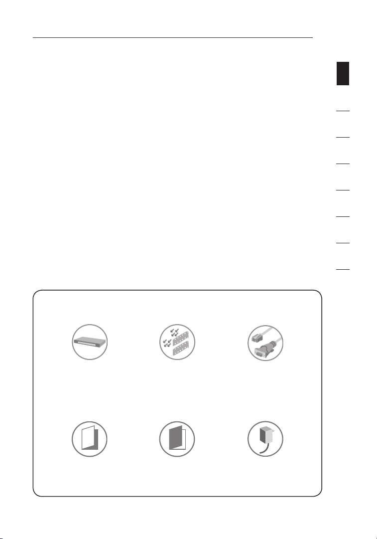
Server Interface Modules
Connecting the SMB CAT5 KVM Switch
to a server requires a custom Belkin
OmniView SMB Server Interface Module
and a standard CAT5 patch cable.
F1DP101A-AP
F1DP101A-AU
F1DP101A-AL
OmniView SMB Server
Interface Modules:
F1DP101AeaAP (PS/2 style)
F1DP101AeaAU (USB style)
F1DP101AeaAL (Legacy Sun™
miniDIN8 style)
F1DP101AeaAP-8P (PS/2 style, 8-pack)
NOTE: Product codes and availability
may vary.
4
Page 8
Overview
A3L791-XX-YYY
A3L850-XX-YYY
A3L980-XX-YYY
F1D108-CBL-XX
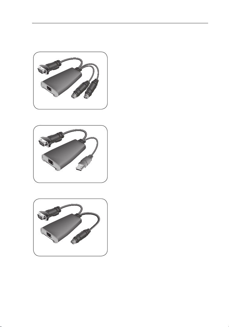
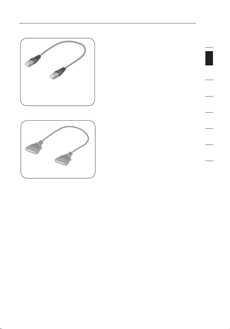
Cables
Belkin highly recommends you use
Belkin Category 5e, FastCAT5e, or
Category 6 Patch Cables for your SMB
CAT5 KVM Switch to help ensure the
superior performance of your video.
These cables offer the highest quality
possible to ensure optimal data and
video transmission.
NOTE: Use CAT6 solid cables for
optimal video at longer lengths.
To connect multiple KVM switches
together, a custom Belkin OmniView
Daisy-Chain cable is required.
Belkin UTP Patch Cables:
A3L791-XX-YYY (CAT5e)
A3L850-XX-YYY (FastCAT5e)
A3L980-XX-YYY (CAT6)
OmniView Daisy-Chain Cable:
F1D108-CBL-XX
(-XX denotes length in feet)
(-YYY denotes color)
NOTE: Product codes and availability
may vary.
1
section
2
3
4
5
6
7
8
5
Page 9

Overview
System Requirements
OS Platforms
The SMB CAT5 KVM Switch is compatible with CPUs running on, but not limited
to, the following OS platforms:
• Windows® NT®, 95, 98, 2000, Me, XP, Server 2003
• Microsoft® DOS 5.x and above
• Red Hat® Linux® 8.x and above
• Novell® NetWare 5.x
• Mac OS® X and above (with USB support)
• Solaris 8.x and above
Keyboards
• PS/2-compatible
• Supports 101-/102-/104-/106-standard-key keyboards
Mice
• PS/2-compatible or PS/2 & USB combo mice (with PS/2 adapter) having 2, 3,
4, or 5 buttons
• PS/2-compatible wireless or optical mice
Monitors
• CRT
• LCD (with VGA support)
66
Page 10
Overview
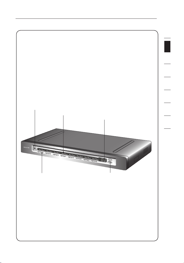
Unit Display Diagrams
Front View of the SMB CAT5 KVM Switch:
1
section
2
3
4
5
6
AutoScan Button 7-Segment LED
Direct-Access Port Selector Manual BANK Scroll Buttons
LED For Selected
Port Identification
For Selected
Identification
BANK
(F1DP116Aea shown)
7
8
7
Page 11
Overview
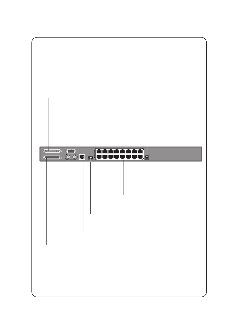
Unit Display Diagrams
Back View of the SMB CAT5 KVM Switch:
Secondary Input
Console PS/2
Mouse/Keyboard
Ports
Primary Input/
Secondary Output
Console VGA
Monitor Port
Flash-Upgrade Port
DC Power Jack
RJ45 CPU Ports
DIP Switch
(F1DP116Aea shown)
8
Page 12

Overview
Specifications
SMB CAT5 KVM Switch
Part No.: F1DP104Aea, F1DP108Aea, F1DP116Aea
Enclosure: Metal enclosure with high-impact plastic
faceplate
Power: 6-volt DC, 1-Amp power adapter with
center-pin positive polarity
Daisy-Chain: Maximum of 16 OmniView KVM Switches
No. of Servers Supported: 4, 8, 16 respectively for 4-port, 8-port,
16-port models (256 servers max via
daisy-chaining)
Console Keyboard Emulation: PS/2
Console Mouse Emulation: PS/2
Monitors Supported: CRT and LCD (with VGA support)
Max. Resolution: Up to 1600x1200@75Hz
Keyboard Input: miniDIN6 (PS/2)
Mouse Input: miniDIN6 (PS/2)
Monitor Port: HDDB15 female (VGA)
CPU Ports: RJ45
1
section
2
3
4
5
6
7
8
Daisy-Chain Ports: DB25 female
Flash-Upgrade Port: RJ11
Direct Port Selectors: 4, 8, 16 respectively for 4-port, 8-port,
16-port models
Operating Temp: 32° to 104° F (0~40° C)
Storage Temp: -4° to 140° F (20~60° C)
Humidity: 0–80% RH, non-condensing
Warranty: 5 years
9
Page 13

Overview
Dimensions: (F1DP104Aea) 11 x 1.75 x 6 in.
(279mm x 44.5mm x 150mm)
(F1DP108Aea) 17.25 x 1.75 x 7.5 in.
(438mm x 44.5mm x 190mm)
(F1DP116Aea) 17.25 x 3.5 x 7.5 in.
(438mm x 89mm x 190mm)
Weight: (F1DP104Aea) 5.3 lbs. (2.4kg.)
(F1DP108Aea) 9.2 lbs. (4.2kg.)
(F1DP116Aea) 12.0 lbs. (5.5kg.)
NOTE: Specifications are subject to change without notice.
SMB Server Interface Module, PS/2
Part No.: F1DP101AeaAP
Emulation: Keyboard and mouse signals
Power: Via attached server; with
Keyboard/Mouse Connection: miniDIN6 (PS/2)
Monitor Connection: HDDB15 male (VGA)
Resolution Support: Up to 1600x1200@75Hz
Max. Distance Supported: 100 ft. (30m)
keep-alive intelligence
Weight: 0.25 lbs. (0.11kg.)
Unit Dimensions: 2.50 x 3.87 x 1.00 in.
(63.5mm x 98.3mm x 25.4mm)
VGA Cable Length: 8 in. (203mm)
PS/2 Cable Length: 19 in. (483mm)
10
Page 14

Overview
SMB Server Interface Module, USB
Part No.: F1DP101AeaAU
Emulation: Keyboard and mouse signals
Power: Via attached server; with keep-alive
intelligence
Keyboard/Mouse Connection: USB Type A
Monitor Connection: HDDB15 male (VGA)
Resolution Support: Up to 1600x1200@75Hz
Max. Distance Supported: 100 ft. (30m)
Weight: 0.25 lbs. (0.11kg.)
Unit Dimensions: 2.50 x 3.87 x 1.00 in.
(63.5mm x 98.3mm x 25.4mm)
VGA Cable Length: 8 in. (203mm)
USB Cable Length: 19 in. (483mm)
SMB Server Interface Module, Legacy Sun
Part No.: F1DP101AeaAL
Emulation: Keyboard and mouse signals
Power: Via attached server; with keep-alive
intelligence
1
section
2
3
4
5
6
7
8
Keyboard/Mouse Connection: miniDIN8 (Legacy Sun)
Monitor Connection: HDDB15 male (VGA)
Resolution Support: Up to 1600x1200@75Hz
Max. Distance Supported: 100 ft. (30m)
Weight: 0.25 lbs. (0.11kg.)
Unit Dimensions: 2.50 x 3.87 x 1.00 in.
(63.5mm x 98.3mm x 25.4mm)
VGA Cable Length: 8 in. (203mm)
USB Cable Length: 19 in. (483mm)
11
Page 15

Installation
Pre-Configuration
Where to Place the SMB CAT5 KVM Switch
The enclosure of the SMB CAT5 KVM Switch is designed for standalone or
rack-mount configuration. The 8- and 16-port SMB CAT5 KVM Switches are
natively rack-mountable in standard 19-inch server racks. Rack-mount hardware
is included with these switches for a sturdy rack installation. An optional RackMount Kit (F1D005) is available for use with the 4-Port SMB CAT5 KVM Switch.
Consider the following when deciding where to place the SMB
CAT5 KVM Switch:
• whether or not you intend to use the direct-access port selectors
• the lengths of the cables attached to your keyboard, monitor, and mouse
• the location of your servers in relation to your console
• the lengths of the cables you use to connect your servers to the SMB CAT5
KVM Switch
Cable Distance Requirements (for PS/2, USB, and Sun Servers)
VGA signals transmit best up to 100 feet (30m). Beyond that length, the
probability of video degradation increases. For this reason, Belkin recommends
that the length of the CAT5 UTP cable between the SMB CAT5 KVM Switch and
the connected servers does not exceed 100 feet (30m).
NOTE: The Belkin CAT5 Extender (F1D084) may be used to extend your console
(keyboard, mouse, and monitor) by up to 500 feet (152m).
WARNING! Avoid placing cables near fluorescent lights, air conditioning
equipment, or machines that create electrical noise (e.g., vacuum cleaners).
You are now ready to begin installation of your SMB CAT5 KVM Switch.
The following sections (pages 13-22) provide complete instructions
for the hardware setup of a single SMB CAT5 KVM Switch (F1DP104A,
F1DP108A, F1DP116A).
Note for Belkin PRO2 Series Owners (F1DA104T, F1DA108T, F1DA116T):
Installation for the PRO2 KVM Switch has changed. Please follow this installation
manual completely to ensure proper installation. Failure to do so may result in
keyboard or mouse errors, and/or faulty operation.
121212
Page 16
Installation
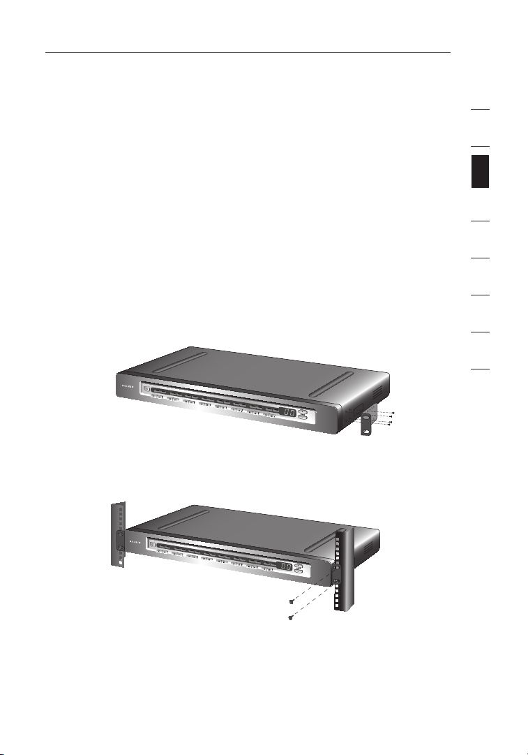
Mounting the SMB CAT5 KVM Switch
Bracket Installation (F1DP108Aea and F1DP116Aea)
Eight- or 16-Port SMB CAT5 KVM Switches include adjustable mounting
brackets ideal for installation in 19-inch racks. The mounting brackets feature
three adjustment positions to allow you to set the SMB CAT5 KVM Switch’s
face flush with the ends of the rails or to extend the SMB CAT5 KVM Switch
past the front of the rails. Please follow these simple steps to achieve the
desired adjustment.
Step 1
Determine how far you would like the SMB CAT5 KVM Switch to protrude
from the rack. Select a bracket-hole scheme.
Step 2
Attach the bracket to the side of your SMB CAT5 KVM Switch using the
Phillips screws provided. (Refer to diagram below.)
Step 3
Mount the SMB CAT5 KVM Switch to the rack-rail assembly. (Refer to
diagram below.)
1
2
section
3
4
5
6
7
8
NOTE: If this SMB CAT5 KVM Switch will be daisy-chained to another KVM
switch, set the BANK address prior to installing on a rack. Refer to the section in
this User Manual labeled “Connecting Multiple SMB CAT5 KVM Switches
(Daisy-Chaining)”.
Your SMB CAT5 KVM Switch is now mounted securely into the bracket and
you are ready to connect the console.
13
Page 17
Installation
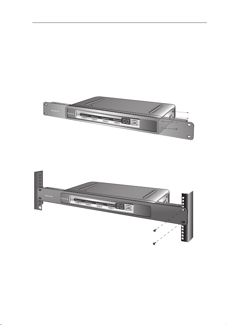
Optional Bracket Installation (F1DP104Aea)
The SMB 4-Port CAT5 KVM Switch can be installed into a 19-inch server rack
using an optional OmniView Rack-Mount Kit (F1D005).
Step 1
Attach the Rack-Mount Bracket to your SMB CAT5 KVM Switch using the
Phillips screws provided. (Refer to diagram below.)
Step 2
Mount the SMB CAT5 KVM Switch to the rack-rail assembly. (Refer to
diagram below.)
NOTE: If this SMB CAT5 KVM Switch will be daisy-chained to another KVM
switch, set the BANK address prior to installing on a rack. Refer to the section
titled “Connecting Multiple SMB CAT5 KVM Switches (Daisy-Chaining)” in this
User Manual.
Your SMB CAT5 KVM Switch is now mounted securely to the rack and
you are ready to connect the console.
14
Page 18
Installation
Connecting the Console to the SMB CAT5 KVM Switch
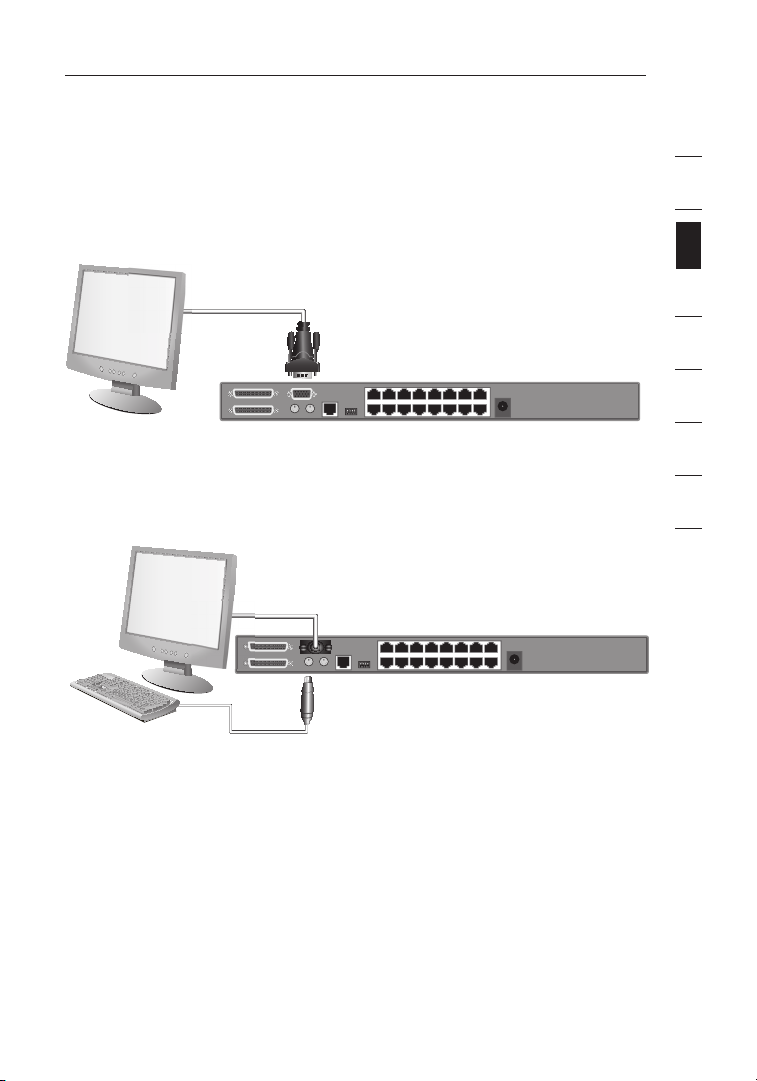
Step 1
Connect the VGA monitor cable to the HDDB15 female port on the
back of the SMB CAT5 KVM Switch in the “Console” section. (Refer to
diagram below.)
Step 2
Connect the PS/2 keyboard cable to the keyboard port on the back of the
SMB CAT5 KVM Switch in the “Console” section. (Refer to diagram below.)
1
2
section
3
4
5
6
7
8
15
Page 19
Installation
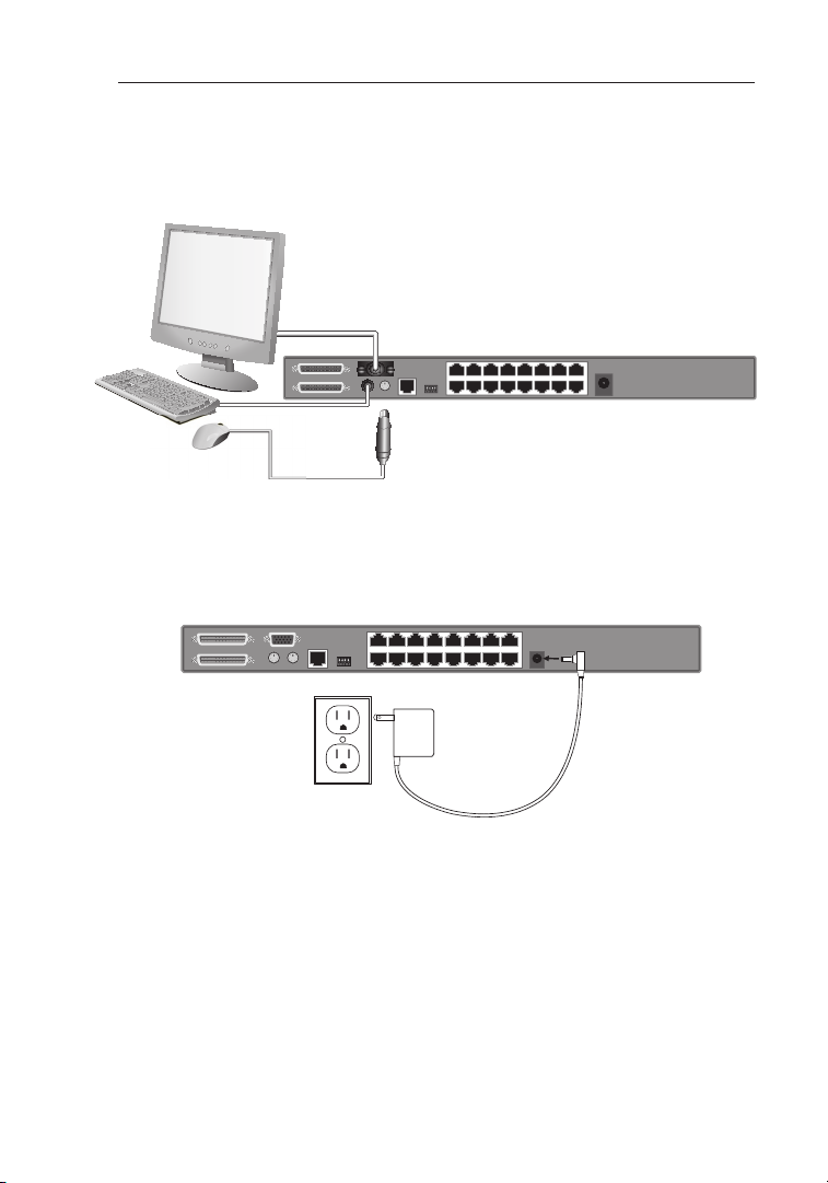
Step 3
Connect the PS/2 mouse cable to the mouse port on the back of the SMB
CAT5 KVM Switch in the “Console” section. (Refer to diagram below.)
Step 4
Attach the power adapter to the DC power jack labeled “6VDC, 1A” located
on the rear panel of the SMB CAT5 KVM Switch. Only use the power adapter
supplied with the unit. (Refer to diagram below.)
(US power adapter shown)
Your SMB CAT5 KVM Switch is now installed and you are ready to
connect your servers.
16
Page 20
Installation
Connecting Servers to the SMB CAT5 KVM Switch
(PS/2 Connection):
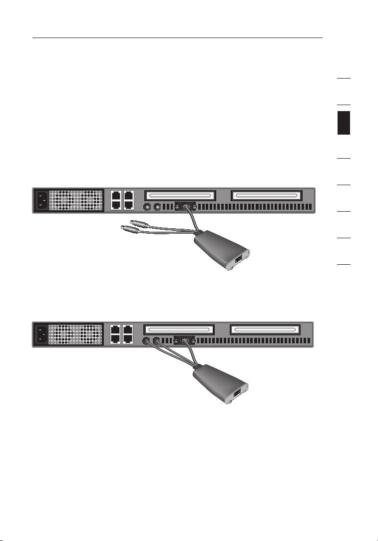
Step 1
Make sure your server is powered off.
Step 2
Using the Belkin OmniView SMB Server Interface Module for PS/2
(F1DP101AeaAP), connect the VGA connector to the monitor port on your
server. (Refer to diagram below.)
Step 3
Connect the PS/2 mouse and then the keyboard connectors to the mouse
and keyboard ports on the server. (Refer to diagram below.)
1
2
section
3
4
5
6
7
8
17
Page 21
Installation
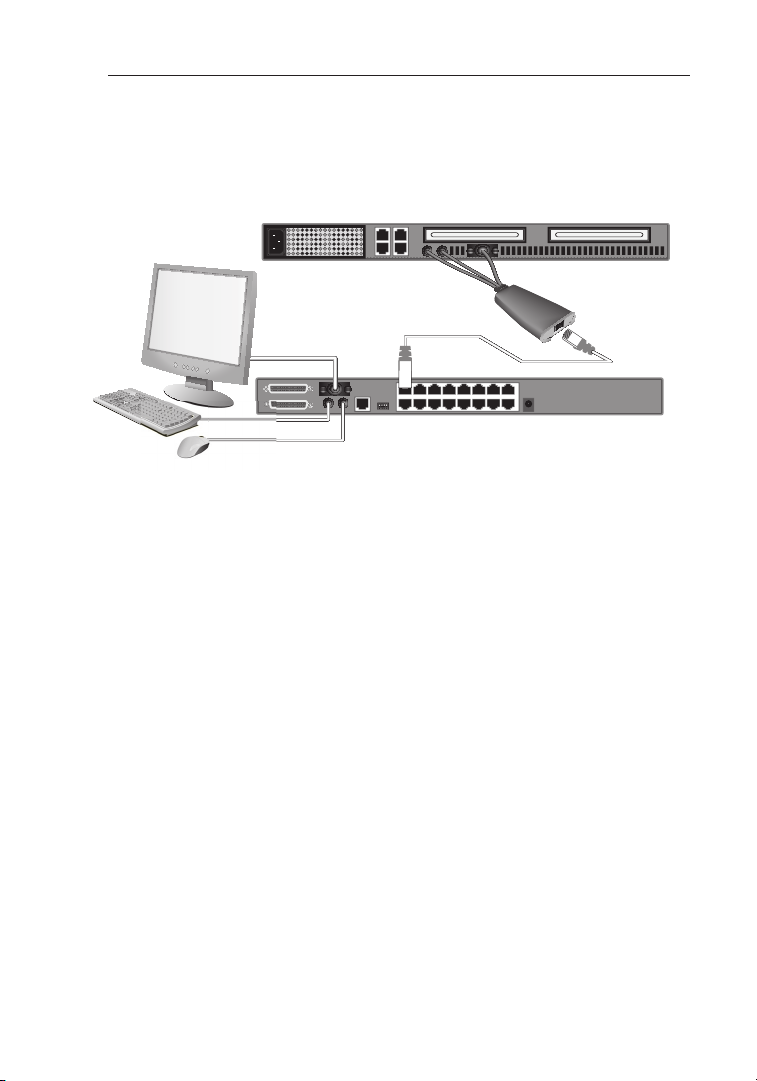
Step 4
Connect the SMB CAT5 KVM Switch to the Server Interface Module using
the included Belkin CAT5e Patch Cable or other CAT5 cable. (Refer to
diagram below.)
Step 5
Power-up your server.
Step 6
Repeat Steps 1 through 5 for each additional PS/2 server you wish
to connect.
18
Page 22
Installation
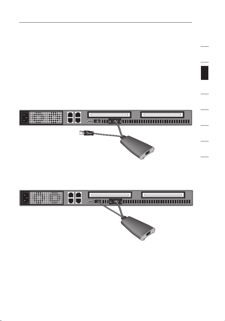
Connecting Servers to the SMB CAT5 KVM Switch
(USB Connection):
Step 1
Make sure your server is powered on.
Step 2
Using the Belkin OmniView SMB Server Interface Module for USB
(F1DP101AeaAU), connect the VGA connector to the monitor port on your
server. (Refer to diagram below.)
Step 3
Connect the USB connector to an available USB port on the server. (Refer to
diagram below.)
1
2
section
3
4
5
6
7
8
19
Page 23
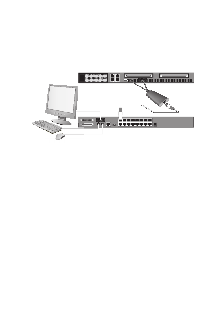
Installation
Step 4
Connect the SMB CAT5 KVM Switch to the Server Interface Module using the
included Belkin CAT5e Patch Cable or other CAT5 cable. (Refer to diagram
below.) Your server should recognize your Server Interface Module and
automatically install the HID USB driver if necessary.
Step 5
Repeat Steps 1 through 4 for each additional USB server you wish
to connect.
NOTE: We recommend you attach the Server Interface Module cable directly to
a free USB port on your server.
20
Page 24
Installation
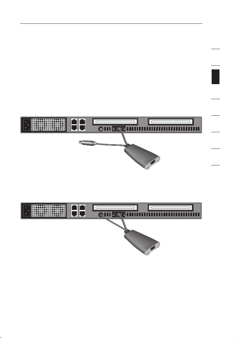
Connecting Servers to the SMB CAT5 KVM Switch
(Sun Server with MiniDIN8 Connection):
Step 1
Make sure your server is powered off.
Step 2
Using the Belkin OmniView SMB Server Interface Module for Legacy Sun
(F1DP101AeaAL), connect the VGA connector to the monitor port on your
server. (Refer to diagram below.)
Step 3
Connect the miniDIN8 connector to the miniDIN8 keyboard port on the
server. (Refer to diagram below.)
1
2
section
3
4
5
6
7
8
21
Page 25
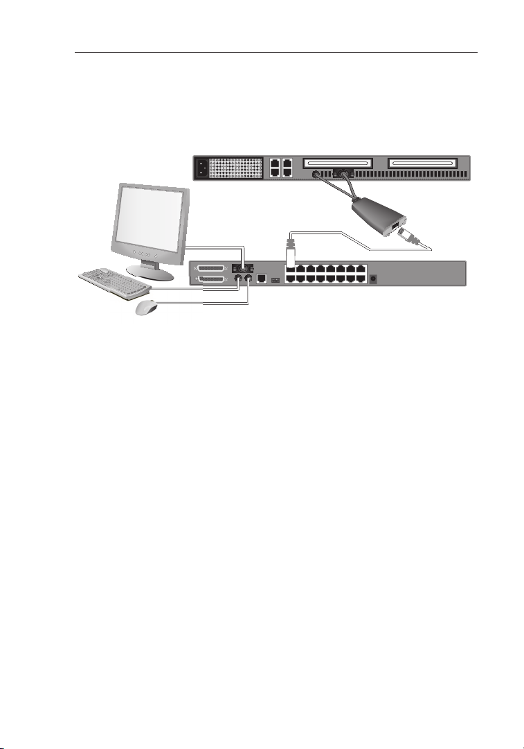
Installation
Step 4
Connect the SMB CAT5 KVM Switch to the Server Interface Module using
the included Belkin CAT5e Patch Cable or other CAT5 cable. (Refer to
diagram below.)
Step 5
Power-up your server.
Step 6
Repeat Steps 1 through 4 for each additional Sun server you wish
to connect.
NOTE: When a USB or Sun Server Interface Module is connected to a Sun
server, the Server Interface Module emulates the Sun keys using a set of key
combinations called Combo Keys. Refer to the table on page 39 for a list of
Sun functions supported by the SMB CAT5 KVM Switch.
2222
Page 26

Installation
Connecting Multiple SMB CAT5 KVM Switches
(Daisy-Chaining)
You can daisy-chain up to 16 SMB CAT5 KVM Switches, allowing a server
administrator to manage up to a maximum of 256 servers from one console.
Each daisy-chained SMB CAT5 KVM Switch is referred to as a “BANK” and is
assigned an address. The SMB CAT5 KVM Switch connected to the console
keyboard, mouse, and monitor is BANK 00 and is referred to as the “primary”
KVM switch. BANKs 01 through 15 are referred to as “secondary” KVM switches.
NOTE: Your SMB CAT5 KVM Switch is backward-compatible with Belkin
OmniView PRO2 KVM Switches. You can daisy-chain any combination of up to
16 SMB CAT5 and PRO2 KVM Switches.
NOTE: A Daisy-Chain Cable (F1D108-CBL) is required to daisy-chain each
SMB CAT5 KVM Switch and is available through your Belkin reseller, or online
at www.belkin.com (U.S. only).
How to Assign a BANK Address
All SMB CAT5 KVM Switches feature a “BANK DIP” switch. The “BANK DIP”
switch is used to assign the proper BANK address to each SMB CAT5
KVM Switch.
• For a single-unit configuration, set the “BANK DIP” switch on the SMB CAT5
KVM Switch to the “primary” (BANK address 00) setting. This is the factory
default setting.
• For a multi-unit configuration, the “BANK DIP” switch on the primary KVM
switch must be set to “BANK address 00”. Each secondary unit must be set to
a unique BANK address (from 01 through 15). Refer to the chart on page 24 for
“BANK DIP” switch settings.
1
2
section
3
4
5
6
7
8
23
Page 27

Installation
BANK DIP Switch Configuration Chart
DIP SWITCH# BANK ADDRESS
1 2 3 4
Down Down Down Down
Up Down Down Down BANK 01 Secondary
Down Up Down Down BANK 02 Secondary
Up Up Down Down BANK 03 Secondary
Down Down Up Down BANK 04 Secondary
Up Down Up Down BANK 05 Secondary
Down Up Up Down BANK 06 Secondary
Up Up Up Down BANK 07 Secondary
Down Down Down Up BANK 08 Secondary
Up Down Down Up BANK 09 Secondary
Down Up Down Up BANK 10 Secondary
Up Up Down Up BANK 11 Secondary
Down Down Up Up BANK 12 Secondary
Up Down Up Up BANK 13 Secondary
Down Up Up Up BANK 14 Secondary
Up Up Up Up BANK 15 Secondary
EXAMPLE:
Four 8-Port SMB CAT5 KVM Switches (F1DP108A) are daisy-chained together
to manage up to 32 servers. The DIP switch on the primary KVM switch is set
to “BANK 00” (factory default) and the secondary units are each set to a unique
BANK (between 01 and 03).
24
Page 28
Installation
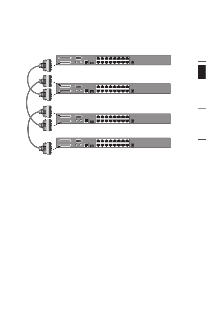
Example of Daisy-Chain Configuration
Primary KVM Switch (BANK 00)
Secondary KVM Switch (BANK 01)
Secondary KVM Switch (BANK 02)
Secondary KVM Switch (BANK 03)
1
2
section
3
4
5
6
7
8
25
Page 29

Installation
Getting Started:
Step 1
Make sure that all servers and SMB CAT5 KVM Switches are powered
off and that each SMB CAT5 KVM Switch has been assigned a unique
BANK address.
Step 2
Place all primary and secondary KVM switches in the desired location.
Step 3
Connect the console monitor, keyboard, and mouse to the console ports of
the primary switch (BANK 00). Refer to “Connecting the Console to the SMB
CAT5 KVM Switch” on page 15.
Connecting the Primary and Secondary KVM Switches:
Step 1
Using the Daisy-Chain Cable (F1D108-CBL), connect one end to the
“Primary Input/Secondary Output” port on the primary KVM switch
(BANK 00).
Step 2
Connect the other end of the Daisy-Chain Cable (F1D108-CBL) to the
“Primary Input/Secondary Output” port of the first secondary KVM switch
(BANK 01).
Step 3
To add additional secondary units, connect one end of the Daisy-Chain
Cable (F1D108-CBL) to the “Secondary Input” on the first secondary KVM
switch and the other end to the “Primary Input/Secondary Output” port of
the next secondary KVM switch (for example, BANK 01).
Step 4
Repeat Step 3 for additional SMB CAT5 KVM Switches you wish to
daisy-chain together.
NOTE: When daisy-chaining SMB CAT5 and PRO2 KVM Switches together, be
sure to set the PRO2 KVM Switches as secondary switches only.
26
Page 30

Installation
Connecting the Servers:
Step 1
Connect all servers to the primary and secondary KVM switches. Refer to
the “Connecting Servers to the SMB CAT5 KVM Switch” section on page 17
for instructions.
Step 2
Make sure that the power adapter is connected to the primary KVM switch
and that the KVM switch is powered on. You should see the primary KVM
switch light up and display the digits “00”, indicating its BANK address.
Step 3
Power up the secondary KVM switches sequentially, beginning with BANK
01, by connecting each unit’s power supply. Each KVM switch should display
its corresponding BANK address number as it is powered up.
NOTE: If the SMB CAT5 KVM Switches do not enumerate correctly, reset the
primary KVM switch (BANK 00) by simultaneously pressing the “BANK +” and
“BANK –” buttons. You can also reset the primary KVM switch to detect newly
added secondary KVM switches. If the KVM switches still do not enumerate
correctly, check that all KVM switches have the correct BANK address assigned
to them and that all daisy-chain cables are connected properly.
Step 4
Verify that the primary KVM switch has detected all secondary KVM switches
by scrolling through the BANKS using the “BANK +” and “BANK –” buttons.
If all secondary KVM switches are detected properly, the LED display on
the primary KVM switch will register and display the BANK address of the
attached secondary KVM switch.
1
2
section
3
4
5
6
7
8
27
Page 31

Installation
Powering Up the Systems
Verify that all servers connected to the SMB CAT5 KVM Switch are powered on.
If any connected servers have not been powered on, it is okay to do so at this
time (servers can be powered on simultaneously). The SMB CAT5 KVM Switch
emulates both a mouse and keyboard on each port and allows your server to
boot normally.
The server connected to Port “1” will be displayed on the monitor. Check that the
keyboard, monitor, and mouse are working normally. Check all occupied ports to
verify that all servers are connected and responding correctly. If you encounter
an error, check your cable connections for that server and reboot. If the problem
persists, please refer to the “Troubleshooting” section in this User Manual.
2828
Page 32

Using Your SMB CAT5 KVM Switch
Now that you have connected your console and servers to your SMB CAT5 KVM
Switch, it is ready for use. Select connected servers by either the direct-access
port selectors, located on the front panel of the SMB CAT5 KVM Switch, using
the On-Screen Display, or by using hot key commands through the console
keyboard. It takes approximately 1–2 seconds for the video signal to refresh
after switching servers. Re-synchronization of the mouse and keyboard signals
also occurs. This is normal operation and ensures that proper synchronization is
established between the console and the connected servers.
Selecting a Server or BANK Using
Hot Key Commands
Switch to the next or previous port with simple keyboard hot key sequences
using the “Scroll Lock” key and either the “Up” or “Down” arrow keys. To
send commands to the SMB CAT5 KVM Switch, the “Scroll Lock” key must
be pressed twice within two seconds. The SMB CAT5 KVM Switch will beep,
confirming that it is in hot key mode. . Next, press the “Up” arrow key and the
SMB CAT5 KVM Switch will switch to the next port. Press the “Down” arrow key
to switch to the previous port. (Refer to diagram below.)
Switch to next active port, “Up” arrow.
With a single-switch configuration (no daisy-chained KVM switches), you can
switch directly to any port by entering the two-digit number of the port you wish
to access. For example, if you press “Scroll Lock”, “Scroll Lock”, “02”, the SMB
CAT5 KVM Switch will switch to the server on Port 2 located on BANK 00.
(Refer to diagram below.)
Switch to previous active port,
“Down” arrow
1
2
3
section
4
5
6
7
8
Switch to BANK 00, Port 2 (02)
2929
Page 33

Using Your SMB CAT5 KVM Switch
With a daisy-chain switch configuration, you can switch between BANKs (KVM
switches) by pressing “Scroll Lock”, “Scroll Lock”, “Page Up”, to switch to the
previous BANK. Press “Scroll Lock”, “Scroll Lock”, “Page Down”, to switch to
the next BANK. (Refer to diagram below.)
With a daisy-chain switch configuration, you can switch directly to any port on
any BANK by pressing “Scroll Lock”, “Scroll Lock”, BANK address, and Port
Number. For example, if you press “Scroll Lock”, “Scroll Lock”, “03”, “05”, the
server on BANK 03, Port 5 will become active. (Refer to diagram below.)
NOTE: You will have approximately five seconds to complete each hot
key sequence.
See page 36 for instructions on how to change the hot key initiator key.
30
Page 34

Selecting a Server Using Direct-Access Port
Selectors
You can directly select which server you wish to control by pressing the directaccess port selector next to the corresponding port. The LED will illuminate to
indicate the port is currently selected. If you are installing multiple SMB CAT5
KVM Switches that are daisy-chained, use the BANK scroll keys located on the
front panel of the primary KVM switch to access other servers that are connected
to the secondary KVM switches.
Selecting a BANK Using Scroll Buttons
Pressing the “BANK +” and “BANK –” scroll buttons on the primary KVM switch
will allow you to switch between the daisy-chained SMB CAT5 KVM Switches.
Pressing both buttons simultaneously will reset the SMB CAT5 KVM Switch.
The “BANK +” button will take you to the next BANK. For example, when you
are at the primary switch (BANK 00) and want to check servers on BANK 02,
pressing the “BANK +” button will take you to BANK 02. As a default, the first
active server will be displayed on the console monitor. Use the direct-access
port selectors to go to the desired server on BANK 02.
The “BANK –” button will take you to the previous BANK (for example, when
you are at BANK 02 and want to check servers in BANK 01). Pressing the
“BANK –” button will take you to BANK 01. As a default, the first active server
will be displayed on the console monitor. Use the direct-access port selectors to
go to the desired server on BANK 01.
1
2
3
section
4
5
6
7
8
31
Page 35

Using Your SMB CAT5 KVM Switch
AutoScan Mode
The AutoScan feature allows you to set your SMB CAT5 KVM Switch to scan and
monitor the activities of all connected servers one by one. The SMB CAT5 KVM
Switch remains on one server for a preset number of seconds, before switching
to the next server. The time interval allotted for each server can be defined or
adjusted through the OSD menu (see the “Scan Time” section).
When the SMB CAT5 KVM Switch is in AutoScan mode, it is also in View-Only
mode. This means that input from the console (keyboard and mouse) will not
be transmitted to the server in focus. Cancel AutoScan to regain control of
the server.
To activate the AutoScan function, press the AutoScan button on the SMB
CAT5 KVM Switch. You can also activate AutoScan on your keyboard by
pressing “Scroll Lock”, “Scroll Lock”, space bar, “F4”.
To disable AutoScan, press any button on the front panel or any key on
the keyboard.
NOTE: There is no mouse or keyboard control in AutoScan mode. This is
necessary to prevent data and synchronization errors. If the user is using the
mouse or keyboard when the SMB CAT5 KVM Switch is switching between
ports, data flow may become interrupted and could result in erratic mouse
movement and/or wrong-character input when using the keyboard.
32
Page 36

ON-SCREEN Display
The On-Screen Display allows you to switch servers, assign names to your
servers, enable and disable the AutoScan feature, set the desired scan time
interval for AutoScan, enable the password security feature, and program hot
keys. To access the On-Screen Display (OSD) menu, press “Scroll Lock”,
“Scroll Lock”, and the space bar. Immediately, the OSD overlay screen will
appear. The superimposed menu screen is generated by the SMB CAT5 KVM
Switch, and does not affect the function of your server, operating system, or
software function.
1
2
3
section
4
Main OSD Menu Page
The main OSD menu displays the current selected BANK and connected servers
to that BANK. If you have only one SMB CAT5 KVM Switch in your configuration,
the OSD menu will display “BANK 00”. A “ ” symbol indicates that the
connected server is powered up. If the OSD menu does not display a “ ”
symbol for a server that is connected and powered up, you will need to reset the
SMB CAT5 KVM Switch to re-detect the server. This is done by simultaneously
pressing the “BANK +” and “BANK –” buttons on the front panel.
5
6
7
8
33
Page 37

Using Your SMB CAT5 KVM Switch
OSD Menu Keyboard Commands
( ) Navigate to different servers in the same BANK
(Page Up/Page Down) Select next or previous BANK
(Insert) Highlight server name for editing
(Enter) Switch servers
(Tab) Open the “Function/Help” page
(Esc) Exit the On-Screen Display
To switch servers using the main OSD menu, use the arrow keys on your
keyboard to navigate to the desired server and press the “ENTER” key.
A “ ” symbol indicates which server is currently being accessed on your
console. To select a different BANK, press the “Page Up” or “Page Down” key
to select the next BANK or the previous BANK. To change the name of a server,
use the arrow keys to navigate to the desired server, press the “Insert” key, type
in the new name, and press “ENTER” to save the entry. You may use up to 15
characters for each server name. To open the “Setup” page, press the “Tab” key.
To exit the On-Screen Display, press the “ESC” key.
34
Page 38

Function/Help Page
1
2
3
section
4
5
6
The “Function/Help” page allows you to set the time intervals for the AutoScan
feature and OSD display time, enable the password security feature, and
program hot keys.
Function/Help Page Keyboard Commands
(F4) Initiate AutoScan
( )
(Insert) Highlight field for editing
(Esc) Return to the main OSD menu
(F10) Program Monitor-DDC2 settings to all Server Interface Modules
(Space) Change options for selected field
Navigate to the next field
Scan
This specifies whether the AutoScan feature is enabled or not. To enable or
disable the AutoScan feature, use the arrow keys to navigate to the “Scan” field
and press the space bar.
Scan Time
This specifies the amount of time the SMB CAT5 KVM Switch remains on a
server before switching to the next server while in AutoScan mode. You may set
the scan time interval to anywhere between 5 and 99 seconds. To change the
scan time, use the arrow keys to navigate to the Scan Time field, type the desired
time interval (in seconds).
7
8
35
Page 39

Using Your SMB CAT5 KVM Switch
Security
This feature allows you to enable an administrator password to prevent
unauthorized users from accessing the OSD. To enable or disable the Security
feature, use the arrow keys to navigate to the “Security” field and press the
space bar.
Admin Password
This allows you to specify the administrator password needed to access the
OSD when the Security feature is enabled. To set the password, use the
arrow keys to navigate to the “Admin Password” field and type in the desired
password. You may use up to eight uppercase characters for the password.
Password characters are not case-sensitive. Press “Esc” or use the arrow keys
to navigate to fields and save the password. Use the “Back Space” key to erase
the password.
Hot Key
This allows you to select which key will be used to initiate hot key commands.
You have four options to choose from: “Scroll Lock”, “Print Screen”, “Left
Ctrl”, and “F12”. The default key for all hot key commands is “Scroll Lock” (see
“Keyboard Hot Key Command Shortcuts” below). To designate a different key to
initiate hot key commands, use the arrow keys to navigate to the “Hot Key” field,
press the space bar until the preferred key is found, and press “Enter” to save
the entry.
36
Page 40

Timeout
This specifies the amount of time that can elapse before the administrator will
be locked out of the KVM Switch (and connected servers) due to user inactivity.
To regain access to the KVM Switch after Timeout, simply reenter the Admin
Password in the login box. The Timeout feature is only available if the Security
feature is enabled. You may set the time intervals to anywhere between 1 and
99 minutes. To change the time interval, use the arrow keys to navigate, type
the desired time interval, and press “Enter” to save the entry. If you disable the
Security feature, the Timeout feature will be turned off automatically.
NOTE: If there are secondary KVM switches connected, and the AutoScan time
and Timeout settings are set on the primary KVM switch, the settings will also
apply to all secondary KVM switches.
1
2
3
section
4
5
Monitor-DDC2 Feature
This feature allows the console monitor to inform the server’s video card about
its properties, such as maximum resolution and color depth. The video card will
then adjust the monitor’s settings accordingly. This enables your monitor to use
its optimal settings for every server connected to your SMB CAT5 KVM Switch.
To read the DDC2 information from the monitor and program it to all connected
Server Interface Modules, press “F10”. Every time you change the monitor, you
will need to press “F10” again to program the new DDC information to the Server
Interface Modules.
6
7
8
37
Page 41

Using Your SMB CAT5 KVM Switch
Keyboard Hot Key Command Shortcuts
Below is a complete list of hot key commands that can be used for your SMB
CAT5 KVM Switch:
SL, SL, Up Arrow Switch to PREVIOUS ACTIVE port
SL, SL,
Down Arrow
SL, SL, Page Up Switch to PREVIOUS BANK
SL, SL,
Page Down
SL, SL, Y Directly switches to PORT Y on BANK 00
SL, SL, X, Y Directly switches to PORT Y on BANK X
SL, SL, Space Bar,
F10
SL, SL, Space Bar Activate On-Screen Display
SL, SL, F4 Enable AutoScan mode (refer to AutoScan button)
Switch to NEXT ACTIVE port
(By default, selects first active port on the BANK)
Switch to NEXT BANK
(By default, selects first active port on the BANK)
(Single-Switch Configuration) Y=01 to 16
(Daisy-Chain Configuration) (X=00 to 15)
(Y=01 to 04 for F1DA104T)
(X=00 to 15) (Y=01 to 08 for F1DA108T)
(X=00 to 15) (Y=01 to 16 for F1DA116T)
Monitor DDC2 (identifies monitor settings)
NOTE: You will have approximately five seconds to complete each hot
key sequence.
38
Page 42

Sun Combo Keys
1
The PS/2 keyboard connected to the SMB CAT5 KVM Switch does not support
the Sun keypad to perform special functions in the Sun operating system
environment. When a USB or Sun Server Interface Module is connected to a Sun
server, the Server Interface Module emulates the Sun keys using a set of key
combinations called Combo Keys. Please refer to the table below.
Sun Key Combo Key
Stop Left Ctrl + Alt + F1
Props Left Ctrl + Alt + F3
Front Left Ctrl + Alt + F5
Open Left Ctrl + Alt +F7
Find Left Ctrl +Alt + F9
Again Left Ctrl + Alt + F2
Undo Left Ctrl + Alt + F4
Copy Left Ctrl + Alt + F6
Paste Left Ctrl + Alt + F8
Cut Left Ctrl + Alt + F10
Help Left Ctrl + Alt + F11
Compose Application key or Left Ctrl + Alt +
Crescent Scroll Lock
Volume Up Left Ctrl + Alt + keypad –
Volume Down Left Ctrl + Alt + keypad +
Mute Left Ctrl + Alt + F12
Sun Left ◊ Key
Sun Right ◊ Key
Alt-Graph Right Alt or Alt Gr
Stop A Left Ctrl + Alt +1
keypad *
Left Windows key
Right Windows key
2
3
section
4
5
6
7
8
39
Page 43

Using Your SMB CAT5 KVM Switch
Updating Firmware
The SMB CAT5 KVM Switch features flash-upgradeable firmware to ensure
compatibility with the latest devices and servers. Firmware upgrades are free for
the life of your SMB CAT5 KVM Switch.
To update your firmware, download the appropriate firmware file and utility
from www.belkin.com/support/. The utility will guide you through the process
of updating the firmware on your SMB CAT5 KVM Switch.
WARNING! We strongly recommend that you update your firmware only if you
are experiencing mouse and keyboard problems with your SMB CAT5 KVM
Switch, as reconfiguring software may lead to unexpected operational problems.
Please contact Belkin Technical Support if you need assistance.
To update the firmware, you will need the following items:
1. A separate server running Windows 2000 or XP. This server must not be
connected to the server ports on the SMB CAT5 KVM Switch.
2. An available serial port on the server.
3. A custom Serial Flash Cable (DB9 male-to-RJ11; included with purchase)
that connects between the SMB CAT5 KVM Switch and the server.
40
Page 44

Frequently Asked Questions
What operating systems does the SMB CAT5 KVM Switch support?
The SMB CAT5 KVM Switch will support any operating system that runs on a
PS/2 and USB platform. Operating systems include, but are not limited to, DOS,
Windows 95/98/2000/Me/NT/XP/2003 Server, Sun, Linux, and Mac OS.
What does flash-upgradeable mean?
With flash-upgrade capability, you can update your SMB CAT5 KVM Switch
firmware at any time through a simple serial connection. Upgrade capability
ensures that your SMB CAT5 KVM Switch is always the most current version
on the market with the latest features and enhancements. See the “Updating
Firmware” section in this User Manual on page 40 for more information.
Does the SMB CAT5 KVM Switch support Microsoft IntelliMouse®?
The SMB CAT5 KVM Switch supports mice from Microsoft, Logitech®,
Kensington®, etc., and Belkin. Please contact Belkin Technical Support for
compatibility issues you may experience.
How does the SMB CAT5 KVM Switch allow the user to switch
between ports?
The SMB CAT5 KVM Switch supports three methods of port selection. The user
can select servers using specially designated keyboard hot keys, through the
On-Screen Display, or can independently access the desired port by pushing the
direct-access port selectors
How far can the server be from the SMB CAT5 KVM Switch?
The SMB CAT5 KVM Switch can be placed up to 100 feet (30m) away from
your server.
1
2
3
4
section
5
6
7
8
41
Page 45

Frequently Asked Questions
What is the maximum video resolution that the SMB CAT5 KVM
Switch supports?
The advanced video circuit in the SMB CAT5 KVM Switch supports a maximum
resolution of up to 1600x1200@75Hz. Increasing the cable length from your SMB
CAT5 KVM Switch to your servers will result in lower resolution support.
Do I have to install any software to use the SMB CAT5 KVM Switch?
No, the SMB CAT5 KVM Switch does not require any drivers or software to be
installed in your servers. Simply connect all your servers to the SMB CAT5 KVM
Switch using Server Interface Modules, and then attach one keyboard, monitor,
and mouse to the console port and it is ready for use.
Does the SMB CAT5 KVM Switch require an AC adapter?
Yes, the SMB CAT5 KVM Switch requires a 5-volt DC, 1-Amp power adapter in
order to function properly.
Can I use the SMB CAT5 KVM Switch to switch video signals only?
No, the Server Interface Modules must be connected to both the video and
keyboard/mouse ports on your servers. The Server Interface Modules require
power from the PS/2, USB, or Sun miniDIN8 ports on your servers in order
to function.
Can I use the SMB CAT5 KVM Switch on my Sun server that supports USB?
Yes, the SMB CAT5 KVM Switch works with any USB-capable server.
Does the SMB CAT5 KVM Switch support Linux?
A: Yes, the SMB CAT5 KVM Switch works with Red Hat® and other Linux
distributions configured for PS/2 or USB support.
How long is the warranty for the SMB CAT5 KVM Switch?
The SMB CAT5 KVM Switch comes with a Five-Year Limited Warranty.
42
Page 46

Troubleshooting
My server does not boot when connected to the SMB CAT5 KVM Switch
but works fine when I connect the keyboard, video, and mouse directly to
the server.
• Make sure that the keyboard and mouse cables are connected tightly
between the Server Interface Module and the server.
• Check that the keyboard and mouse cables are not crossed.
• Check the CAT5 cable connection.
I am getting ghosting, shadowing, or fuzzy images on my monitor.
• Check that all video cables are inserted properly to the Server
Interface Module.
• Check that the monitor you are using supports the resolution and refresh-rate
setting on your server.
• Lower the video resolution of your monitor.
• Check that the cable length does not exceed 100 feet (30m).
• Check that the graphics card you are using supports the resolution and
refresh-rate setting on your server.
• Connect the monitor directly into the server you are having trouble with to see
if the problem still appears.
I am getting a black screen on my monitor.
• Check that all video cables are inserted properly.
• Check that the keyboard cable is connected and inserted properly between
the server and the Server Interface Module for the appropriate port.
• Connect your monitor directly to the server to verify that your monitor is
functioning properly.
1
2
3
4
5
section
6
7
8
43
Page 47

Troubleshooting
The server does not detect a keyboard and I get a keyboard error reported
at boot–up.
• Check that the keyboard cable on the Server Interface Module is completely
connected to your server. Tighten any loose connections.
• If you are using the keyboard software that was included with your keyboard,
uninstall it and then reinstall the standard Microsoft keyboard driver.
The mouse is lost when I switch to a different port.
• Check that the mouse you are using is connected properly to the console port
of the SMB CAT5 KVM Switch.
• Check that the mouse cable on the Server Interface Module is completely
connected to your server. Tighten any loose connections.
• If you are using a mouse driver that was included with your mouse, uninstall it
and install the standard Microsoft mouse driver.
• Make sure the mouse works when directly plugged into the server.
• If the server is coming out of standby mode, allow up to one minute to regain
mouse function.
• De-activate power-management schemes on the PC with which you are
experiencing problems.
• Try a different mouse.
The mouse is not detected at boot-up.
• Check the cables and make sure that they are inserted correctly.
The server boots up, but the mouse does not work.
• Make sure the mouse is plugged in properly.
• Make sure the mouse works when directly plugged into the server. Rebooting
may be necessary when trying this.
• Try a different mouse.
44
Page 48

Troubleshooting
When I switch from one port to another, mouse movement is
completely erratic.
• Make sure you do not have more than one mouse driver installed. Make sure
that the driver is either for a standard PS/2 mouse or a Microsoft servercompatible PS/2 mouse.
• Make sure you do not have any mouse drivers loaded in your “CONFIG.SYS”
or “AUTOEXEC.BAT” files.
• Avoid moving the mouse or pressing the mouse button when switching ports
on the SMB CAT5 KVM Switch.
• Stop moving the mouse, wait for five seconds, and then move the mouse
again. The Server Interface Module will synchronize the mouse movement
automatically.
USB
I am connecting the USB Server Interface Module to my USB server and my
keyboard and mouse do not work.
• Prior to connecting the USB Server Interface Module, make sure that the HID
USB driver is installed on each server. (To install the HID USB driver, connect
a USB mouse and USB keyboard to the server. A Windows operating system
should automatically install the drivers.)
Some of the keys on my keyboard are not functioning properly when I use a
Mac® server.
• If you are using a PC keyboard on a Mac system, a few of the option keys on
your PC keyboard may be reversed. All major keys will function as labeled.
1
2
3
4
5
section
6
7
8
45
Page 49

Glossary
The following definitions are used throughout this User Manual:
AutoScan: A mode of operation where the KVM switch scans from one port to
another, on an ongoing basis, as configured by the user.
BANK: The address of a daisy-chained KVM switch (00–15), set by the
DIP switch.
Console:
connected to a KVM switch.
Console Port: Receptors for the console to connect to the KVM switch.
Control: When discussing switching between ports, control means that the
console is capable of sending input to the server. Control requires that the
console also has focus on the port, and is viewing it.
Daisy-Chain: A configuration of multiple KVM switches that are connected one
to another in a series. A KVM switch daisy-chain uses common settings to allow
seamless, complex interactions between multiple consoles for control over
many servers.
DDC:
between a monitor and a video adapter. Using DDC, a monitor can inform
a computer’s video card about its properties, such as maximum resolution
and color depth, to ensure that the user is presented with valid options for
configuring the display.
The all-in-one term for the keyboard, video monitor, and mouse
Short for Display Data Channel, a VESA standard for communication
46
Page 50

Glossary
HID: Human Interface Device, the USB device class that includes keyboards
and mice.
KVM: Literally “Keyboard Video Mouse”, this term refers to technology that
allows two or more computers to be controlled by one keyboard, video monitor,
and mouse; some switches that use KVM technology enable sharing of other
peripherals such as audio speakers, microphones, and printers.
KVM Switch: A device that allows a user to access and control multiple servers
from a single console. It has at least one console port and multiple server ports.
OSD: On-Screen Display, a Graphical User Interface that can be used to control
and configure the KVM Switch.
Port: An interface receptor on a server through which you can attach a device or
plug in a device cable.
Primary KVM Switch: The KVM switch that is connected to the console and is
set to BANK address 00.
Secondary KVM Switch: Any KVM switch that is daisy-chained to the primary
KVM switch and is set to BANK address 01–15 (and has no console connected).
1
2
3
4
5
6
section
7
8
47
Page 51

Information
FCC Statement
Declaration of Conformity with FCC Rules
for Electromagnetic Compatibility
We, Belkin Corporation, of 501 West Walnut Street, Compton, CA 90220, declare under our
sole responsibility that the products:
F1DP104A, F1DP108A, F1DP116A,
to which this declaration relates:
Comply with Part 15 of the FCC Rules. Operation is subject to the following two
conditions: (1) this device may not cause harmful interference, and (2) this device must accept
any interference received, including interference that may cause undesired operation.
CE Declaration of Conformity
We, Belkin Corporation, declare under our sole responsibility that the products F1DP104A,
F1DP108A, F1DP116A, to which this declaration relates, are in conformity with Emissions
Standard EN55022 and with Immunity Standard EN55024, LVP EN61000-3-2, and EN61000-3-3.
ICES
This Class B digital apparatus complies with Canadian ICES-003. Cet appareil numérique de la
classe B est conforme á la norme NMB-003 du Canada.
Belkin Corporation Limited Five-Year Product Warranty
Belkin Corporation warrants this product against defects in materials and workmanship for
its warranty period. If a defect is discovered, Belkin will, at its option, repair or replace the
product at no charge provided it is returned during the warranty period, with transportation
charges prepaid, to the authorized Belkin dealer from whom you purchased the product.
Proof of purchase may be required. This warranty does not apply if the product has been
damaged by accident, abuse, misuse, or misapplication; if the product has been modified
without the written permission of Belkin; or if any Belkin serial number has been removed or
defaced.
THE WARRANTY AND REMEDIES SET FORTH ABOVE ARE EXCLUSIVE IN LIEU OF
ALL OTHERS, WHETHER ORAL OR WRITTEN, EXPRESSED OR IMPLIED. BELKIN
SPECIFICALLY DISCLAIMS ANY AND ALL IMPLIED WARRANTIES, INCLUDING, WITHOUT
LIMITATION, WARRANTIES OF MERCHANTABILITY AND FITNESS FOR A PARTICULAR
PURPOSE.
No Belkin dealer, agent, or employee is authorized to make any modification, extension, or
addition to this warranty.
BELKIN IS NOT RESPONSIBLE FOR SPECIAL, INCIDENTAL, OR CONSEQUENTIAL
DAMAGES RESULTING FROM ANY BREACH OF WARRANTY, OR UNDER ANY OTHER
LEGAL THEORY, INCLUDING BUT NOT LIMITED TO, LOST PROFITS, DOWNTIME,
GOODWILL, DAMAGE TO OR REPROGRAMMING, OR REPRODUCING ANY PROGRAM OR
DATA STORED IN OR USED WITH BELKIN PRODUCTS.
Some states do not allow the exclusion or limitation of incidental or consequential damages or
exclusions of implied warranties, so the above limitations or exclusions may not apply to you.
This warranty gives you specific legal rights, and you may also have other rights that vary
from state to state.
1
2
3
4
5
6
7
section
8
48
Page 52

Switch KVM
CAT5 OmniView
®
SMB
Contrôlez
Contrôlez vos serveurs à l’aide d’une console
PS/2 et d’un câblage CAT5
Manuel de l’utilisateur
F1DP104Aea
F1DP108Aea
F1DP116Aea
Page 53

Switch KVM SMB
CAT5 OmniView
®
Belkin Ltd.
Express Business Park, Shipton Way
Rushden, NN10 6GL, Royaume-Uni
+44 (0) 1933 35 2000
+44 (0) 1933 31 2000 Fax
Belkin B.V.
Boeing Avenue 333
1119 PH Schiphol-Rijk, Pays-Bas
+31 (0) 20 654 7300
+31 (0) 20 654 7349 Fax
Assistance Technique Belkin
Europe : 00 800 223 55 460
© 2005 Belkin Corporation. Tous droits réservés. Toutes les raisons commerciales sont des
marques déposées de leurs fabricants respectifs. Mac et Mac OS sont des marques de
commerce de Apple Computer, Inc., enregistrées aux États-Unis et dans d’autres pays.
Belkin GmbH
Hanebergstraße 2
80637 Munich, Allemagne
+49 (0) 89 143405 0
+49 (0) 89 143405 100 Fax
Belkin SAS
5 Rue du Petit Robinson, 3ème étage
78350 Jouy en Josas, France
+33 (0) 1 34 58 14 00
+33 (0) 1 39 46 62 89 Fax
P74902ea
Page 54

Table des matières
Table des matières
1. Introduction ........................................................................................... 1
Contenu de l’emballage .................................................................................1
2. Présentation .......................................................................................... 2
Présentation des fonctions ............................................................................2
Configuration requise ....................................................................................4
Configuration requise ....................................................................................6
Illustrations de l’unité .....................................................................................7
Spécifications ...............................................................................................9
3. Installation .......................................................................................... 12
Préconfiguration ..........................................................................................12
Montage du Switch KVM CAT5 SMB .........................................................13
Branchement du Switch KVM CAT5 SMB ..................................................15
Branchement des serveurs au Switch KVM CAT5 SMB .............................17
Connexion de plusieurs unités KVM CAT5 SMB
(montage en série) .......................................................................................23
Mise en route des systèmes ........................................................................28
4. Utilisation de votre Switch KVM CAT5 SMB .......................................... 29
Sélection d’un ordinateur à l’aide des raccourcis clavier .............................29
Sélection d’un ordinateur à l’aide des sélecteurs de port à accès direct ....31
Sélection d’un BANK à l’aide des boutons de défilement ...........................31
Mode AutoScan ...........................................................................................32
Affichage à l’écran .......................................................................................33
Commandes avec raccourcis clavier ...........................................................38
Touches combo Sun ...................................................................................39
Mise à jour du micrologiciel .........................................................................40
5. Foire aux questions ............................................................................ 41
6. Dépannage .......................................................................................... 43
7. Glossaire ............................................................................................. 46
8. Informations ........................................................................................ 48
Page 55

Introduction
Félicitations! Vous avez fait l’achat du Switch KVM CAT5 OmniView SMB de
Belkin. Notre gamme variée de solutions KVM vous montre comment Belkin
s’engage à fournir des produits de grande qualité, résistants à un prix abordable.
Belkin vous offre le seul Switch KVM pour petites et moyennes entreprises
qui permet une gestion aisée de serveurs multi plateformes: le Switch KVM
CAT5 OmniView SMB. Conçu pour livrer une excellente performance à un prix
abordable, ce Switch permet une gestion centralisée des environnements de
serveurs de taille moyenne se trouvant en centre de données, en laboratoire ou
en succursale. Les Switchs KVM CAT5 SMB peuvent être montés en série, ce
qui vous permet de contrôler jusqu’à 256 serveurs PS/2, USB et Sun à partir
d’une seule console PS/2. La mise en oeuvre de la technologie CAT5 Belkin et
des Modules d’interface serveurs compacts simplifient l’installation, garantissant
la plus haute stabilité et un meilleur temps de disponibilité des serveurs. La
gamme de produits KVM CAT5 SMB offre des fonctions qui se retrouvent
habituellement sur les solutions haut de gamme.
Ce manuel vous donnera des détails sur votre nouveau Switch KVM CAT SMB,
de l’installation et du fonctionnement jusqu’au dépannage, dans le cas peu
probable où vous rencontreriez un problème. Pour une installation rapide et
simple, reportez-vous au Guide d’installation rapide fourni avec votre Switch
KVM CAT5 SMB.
Merci d’avoir choisi le Switch KVM CAT5 OmniView SMB de Belkin. Merci de
votre confiance. Vous allez vite constater pourquoi Belkin est le meilleur vendeur
de Switchs KVM à travers le monde.
Contenu de l’emballage
section
1
2
3
4
5
6
7
8
Switch KVM CAT5
OmniView SMB
Guide d’utilisation Guide
Supports de montage
avec
vis (F1DP108A,
F1DP116A)
d’Installation
Rapide
Câble flash
série DB9 vers
RJ11
Bloc d’alimentation
6V CC,
1A
11
Page 56

Présentation
Présentation des fonctions
• Technologie CAT5
La technologie CAT5 intégrée vous permet de brancher votre Switch KVM à
vos serveurs situés jusqu’à 30 mètres de ceux-ci, grâce à un câblage CAT5
standard et les Modules d’interface serveur compacts de Belkin. Le câblage
CAT5 diminue l’enchevêtrement des câbles, simplifie la gestion de ceux-ci
et facilite la circulation de l’air dans les bâtis, prolongeant ainsi la longévité
de votre équipement. Les Modules d’interface serveur garantissent un temps
de disponibilité en continu grâce à une technologie d’entretien et l’émulation
complète du signal du clavier et de la souris.
• Port servant exclusivement au montage en série
Vous pouvez monter jusqu’à 16 Switchs KVM en série grâce aux ports
servant exclusivement à cette fin, et ainsi étendre votre configuration KVM
pour répondre à vos besoins grandissants.
• Résolution vidéo prise en charge
Le Switch KVM CAT5 SMB prend en charge les résolutions jusqu’à
1600 x 1200 @ 70 Hz.
• Affichage à l’écran (OSD)
La fonction OSD simplifie la gestion des serveurs en vous permettant
d’attribuer des noms distincts à chaque serveur connecté du système. Vous
disposez d’un moyen visuel de permuter entre les ordinateurs et de définir
l’intervalle pour la fonction AutoScan.
• Raccourcis clavier
La fonction de raccourci clavier vous permet de sélectionner le port souhaité à
l’aide des commandes de clavier indiquées. En utilisant une simple séquence
de raccourci sur votre clavier, vous pouvez choisir instantanément un serveur
parmi les 256 possibles.
22
Page 57

Présentation
• Bouton de la face avant
Des sélecteurs de ports à accès direct, placés sur la face avant du Switch
KVM CAT5 SMB, vous permettent de choisir un port simplement et
manuellement.
• AutoScan
La fonction AutoScan vous permet d’indiquer à la Console avec Switch
KVM CAT5 SMB d’analyser et de surveiller les activités de tous les serveurs
connectés, l’un après l’autre. L’intervalle alloué à chaque serveur peut être
défini ou ajusté par l’intermédiaire du menu OSD (On-Screen Display).
• Témoin
Les témoins de la face avant du Switch KVM CAT5 SMB jouent le rôle d’un
moniteur d’état. Le témoin DEL situé au-dessus de chaque sélecteur de port
à accès direct s’allume pour indiquer que la console contrôle actuellement
le serveur correspondant. Lorsque vous appuyez sur un sélecteur de port, le
témoin situé à côté s’allume. Ce témoin clignote pour vous indiquer qu’aucun
ordinateur n’est connecté à ce port.
• Témoin en sept segments
Lorsque vous montez en série plusieurs Switchs KVM CAT5 SMB, le témoin
en sept segments vous indique rapidement le BANK sélectionné.
• Mise à niveau Flash
Le micrologiciel pouvant être mis à niveau par mémoire flash permet que votre
Switch KVM CAT5 SMB soit mis à jour avec le tout dernier micrologiciel. Ceci
lui permet de rester constamment compatible avec les derniers périphériques
et serveurs. Les mises à niveau son gratuites pour toute la durée de vie
de votre Switch KVM CAT5 SMB et peuvent être téléchargées du site de
l’assistance technique Belkin à www.belkin.com/support.
1
section
2
3
4
5
6
7
8
3
3
Page 58

Présentation
Configuration requise
Modules d’interface serveur
Pour brancher le Switch KVM CAT5 SMB
à un serveur, vous devez disposer d’un
Module d’interface serveur OmniView
SMB Belkin et un câble de raccordement
CAT5 standard.
F1DP101A-AP
F1DP101A-AU
F1DP101A-AL
Modules d’interface
serveur SMB OmniView® :
F1DP101AeaAP (PS/2)
F1DP101AeaAU (USB)
F1DP101AeaAL (Système patrimonial
Sun™ miniDIN8)
F1DP101AeaAP-8P (PS/2, pack de 8)
REMARQUE : Les codes de produits et
la disponibilité de ces derniers peuvent
varier.
4
Page 59

Présentation
A3L791-XX-YYY
A3L850-XX-YYY
A3L980-XX-YYY
F1D108-CBL-XX
Câbles
Belkin recommande fortement l’utilisation
des câbles de raccordement Catégorie
5e, FastCAT5e, ou Category 6 avec votre
Switch KVM CAT5 SMB afin d’assurer
une meilleure performance de votre
vidéo. Ils offrent la plus grande qualité
possible afin d’assurer une transmission
de données optimale.
REMARQUE : Utilisez des câbles CAT6
solides pour une qualité vidéo optimale
sur de longues distances.
Pour brancher plusieurs serveurs KVM
entre eux, vous devez utiliser un Câble
de montage en série OmniView Série
Belkin.
Câbles de raccordement UTP
Belkin :
A3L791-XX-YYY (CAT5e)
A3L850-XX-YYY (FastCAT5e)
A3L980-XX-YYY (CAT6)
Câbles de montage en série
OmniView
F1D108-CBL-XX
1
section
2
3
4
5
6
7
8
(-XX indique la longueur en pieds)
(-YYY indique la couleur)
REMARQUE : Les codes de produits et
la disponibilité de ces derniers peuvent
varier.
5
Page 60

Présentation
Configuration requise
Systèmes d’exploitation
Le Switch KVM CAT5 SMB est compatible avec des unités centrales sous les
plate-formes suivantes (liste non exhaustive) :
• Windows® NT®, 95, 98, 2000, Me, XP, Server 2003
• Microsoft® DOS 5.x et supérieur
• Red Hat® Linux® 8.x et supérieur
• Novell® NetWare 5.x
• Mac OS® X et supérieur (avec prise en charge USB)
• Solaris 8.x et supérieur
Claviers
• Compatible PS/2
• Prend en charge les claviers standard à 101, 102, 104 et 106 touches
Souris
• Souris PS/2 ou PS/2 et USB (avec adaptateur PS/2) à 2, 3, 4 ou 5 boutons
• Souris sans fil ou optique PS/2
Moniteurs
• CRT
• LCD (avec prise en charge VGA)
66
Page 61

Présentation
Illustrations de l’unité
Face avant du Switch KVM CAT5 SMB :
Bouton AutoScan
TÉMOIN Pour
l’identification du port
sélectionné
Témoin DELen 7 segments pour
l’identification du
BANK sélectionné
1
section
2
3
4
5
6
7
8
Sélecteur de port à accès direct Boutons de défilement manuel des
(F1DP116Aea shown)
BANK
7
Page 62

Présentation
Illustrations de l’unité
Face arrière du Switch KVM CAT5 SMB :
Entrée secondaire
Ports PS/2 souris/
clavier de la
console
Entrée principale/
sortie secondaire
Prise d’alimentation CC
Port VGA de la Console
Ports RJ45 des CPU
Commutateur DIP
Port de mise à niveau Flash
(F1DP116Aea montré)
8
Page 63

Présentation
Caractéristiques techniques
Switch KVM CAT5 SMB
Référence : F1DP104Aea, F1DP108Aea,
F1DP116Aea
Boîtier : Boîtier métallique avec face plastique
hautement résistante
Alimentation : Adaptateur de courant 6 volts CC, 1
A avec polarité positive sur la broche
centrale
Configuration en série : Maximum de 16 Switchs KVM OmniView
Nombre de serveurs pris en charge : 4, 8 et 16 respectivement pour
les modèles à 4, 8 et 16 ports
(maximum de 256 serveurs
montés en série)
Émulation du clavier de la console : PS/2
Émulation de la souris de la console : PS/2
Moniteurs pris en charge : CRT et LCD (avec prise en charge VGA)
Résolution maximum : Jusqu’à 1600 x 1200 @ 75 Hz
Entrée clavier : miniDIN6 (PS/2)
Entrée souris : miniDIN6 (PS/2)
Port du moniteur : HDDB15 femelle (VGA)
1
section
2
3
4
5
6
7
8
Ports CPU : RJ45
Port de montage en série : DB25 femelle
Port de mise à niveau Flash : RJ11
Sélecteurs de port à accès direct : 4, 8 et 16 respectivement pour
les modèles à 4, 8 et 16 ports
Température de fonctionnement : 0° ~ 40 °C
Température de stockage : -20° ~ 60 °C
Humidité : de 0 à 80 % d’humidité relative sans
condensation
Garantie : 5 ans
9
Page 64

Présentation
Dimensions : (F1DP104Aea) 279 mm x 44,5 mm x 150 mm
(F1DP108Aea) 438 mm x 44,5 mm x 190 mm
(F1DP116Aea) 438 mm x 89 mm x 190 mm
Poids : (F1DP104Aea) 2,4 kg
(F1DP108Aea) 4,2 kg
(F1DP116Aea) 5,5 kg
REMARQUE : Ces spécifications sont sujettes à modification sans préavis.
Module d’interface serveur SMB OmniView, PS/2
Référence : F1DP101AeaAP
Émulation : Signaux du clavier et de la souris
Alimentation : Via le serveur branché, avec
Connexion clavier/souris : miniDIN6 (PS/2)
Connexion moniteur : HDDB15 mâle (VGA)
Résolutions prises en charge : Jusqu’à 1600 x 1200 @ 75 Hz
Distance max. prise en charge : 30 m
Poids : 0,11 kg
Dimensions de l’unité : 63,5 mm x 98,3 mm x 25,4 mm
Longueur du câble VGA : 203 mm
technologie d’entretien
Longueur du câble PS/2 : 483 mm
10
Page 65

Présentation
Module d’interface serveur OmniView SMB, USB
Référence : F1DP101AeaAU
Émulation : Signaux du clavier et de la souris
Alimentation : Via le serveur branché, avec
technologie d’entretien
Connexion clavier/souris : USB, Type A
Connexion moniteur : HDDB15 mâle (VGA)
Résolutions prises en charge : Jusqu’à 1600 x 1200 @ 75 Hz
Distance max. prise en charge : 30 m
Poids : 0,11 kg
Dimensions de l’unité : 63,5 mm x 98,3 mm x 25,4 mm
Longueur du câble VGA : 203 mm
Longueur du câble USB : 483 mm
Module d’interface serveur OmniView SMB, système
patrimonial Sun
Référence : F1DP101AeaAL
Émulation : Signaux du clavier et de la souris
Alimentation : Via le serveur branché, avec
technologie d’entretien
1
section
2
3
4
5
6
7
8
Connexion clavier/souris : miniDIN8 (système patrimonial Sun)
Connexion moniteur : HDDB15 mâle (VGA)
Résolutions prises en charge : Jusqu’à 1600 x 1200 @ 75 Hz
Distance max. prise en charge : 30 m
Poids : 0,11 kg
Dimensions de l’unité : 63,5 mm x 98,3 mm x 25,4 mm
Longueur du câble VGA : 203 mm
Longueur du câble USB : 483 mm
11
Page 66

Installation
Préconfiguration
Où installer le Switch KVM CAT5 SMB
Le boîtier du Switch KVM CAT5 SMB est conçu pour être installé de manière
autonome ou dans une baie. Les modèles KVM CAT5 SMB à 8 et 16 ports
peuvent, d’origine, être montés dans des baies standard de 19 pouces. Le
matériel d’installation est fourni avec ces switchs pour un montage solide. Un kit
de montage optionnel (F1D005) est disponible pour le Switch KVM CAT5 SMB à
4 ports.
Prenez en considération les éléments suivants avant d’installer
votre Switch KVM CAT5 SMB :
• Pensez-vous utiliser les sélecteurs de ports à accès direct ;
• La longueur des câbles reliés au clavier, au moniteur et à la souris ;
• L’emplacement de vos unités centrales reliées à votre console ;
• La longueur des câbles utilisés pour brancher vos serveurs au Switch KVM
CAT5 SMB
Distance des câbles (pour serveurs PS/2, USB et Sun)
La transmission des signaux VGA s’effectue bien jusqu’à 30 mètres. Au-delà, les
probabilités de dégradation vidéo augmentent. Ainsi, Belkin vous recommande
de ne pas utiliser un câblage CAT5 UTP de plus de 30 mètres, entre votre Switch
KVM CAT5 SMB et les serveurs branchés.
REMARQUE : Le Module d’extension CAT5 Belkin (F1D084) peut servir à
rallonger la portée de votre console (clavier, souris et moniteur de 152 mètres
supplémentaires.
AVERTISSEMENT ! Ne placez pas les câbles près de lumières fluorescentes,
de systèmes de climatisation ou de machines produisant du bruit électrique
(aspirateurs, par exemple).
Vous êtes maintenant prêt à installer votre Switch KVM CAT5 SMB.
Les sections suivantes (pages 13 à 32) comprennent des instructions
complètes pour l’installation matérielle d’un Switch KVM CAT5 SMB
(F1DP104A, F1DP108A, F1DP116A).
Remarque aux propriétaires d’un produit PRO2 Belkin (F1DA104T,
F1DA108T, F1DA116T) :
Suivez scrupuleusement ce manuel d’installation afin de vous assurer d’une
installation adéquate. Si vous ne le faites pas, vous risquez de rencontrer des
erreurs de clavier ou de souris et/ou des problèmes de fonctionnement.
121212
L’installation du Switch KVM PRO2 KVM a changé.
Page 67

Installation
Montage du Switch KVM CAT5 SMB
Installation des supports (F1DP108Aea et F1DP116Aea)
Les Switchs KVM SMB CAT5 à 8 ou 16 ports sont livrés avec des fixations de
montage réglables qui conviennent parfaitement à une installation dans une
baie de 19 pouces. Les supports de montage peuvent être ajustées selon trois
positions, ce qui permet de placer la face du Switch de façon à ce qu’elle soit
alignée avec la fin des rails ou pour placer le Switch de façon à ce qu’il dépasse
le devant des rails. Suivez cette procédure simple pour parvenir au réglage
souhaité.
Étape 1
Déterminez la profondeur à laquelle vous désirez installer le Switch KVM
CAT5 SMB dans le bâti. Choisissez les orifices des fixations adaptés.
Étape 2
Placez la fixation sur le côté du votre Switch KVM CAT5 SMB à l’aide des vis
cruciformes fournies. (Reportez-vous à l’illustration ci-dessous.)
Étape 3
Montez le Switch KVM CAT5 SMB sur le montage rail/bâti. (Reportez-vous à
l’illustration ci-dessous.)
1
2
section
3
4
5
6
7
8
REMARQUE : Si vous devez monter le Switch KVM CAT5 SMB en série avec
un autre Switch KVM, réglez l’adresse BANK avant de l’installer dans la baie.
Reportez-vous à la section « Installation de plusieurs Switchs KVM CAT5 SMB
(montage en série) » du présent manuel.
Votre Switch KVM CAT5 SMB est maintenant solidement ancré au bâti.
Vous pouvez maintenant brancher la console.
13
Page 68

Installation
Installation des supports en option (F1DP104Aea)
Le Switch KVM CAT5 SMB à 4 Ports peut être installé dans un bâti de serveur de
19 pouces à l’aide du Kit de montage en baie OmniView (F1D005).
Étape 1
Placez la fixation sur le côté du votre Switch KVM CAT5 SMB à l’aide des vis
cruciformes fournies. (Reportez-vous à l’illustration ci-dessus.)
Étape 2
Montez le Switch KVM CAT5 SMB sur le montage rail/bâti. (Reportez-vous à
l’illustration ci-dessous.)
REMARQUE : Si vous devez monter le Switch KVM CAT5 SMB en série avec
un autre Switch KVM, réglez l’adresse BANK avant de l’installer dans la baie.
Consultez la section « Branchement de multiples Switchs KVM (montage en
série) » du manuel de l’utilisateur du Switch KVM CAT5 SMB.
Votre Switch KVM CAT5 SMB est maintenant solidement ancré au bâti.
Vous pouvez maintenant brancher la console.
14
Page 69

Installation
Branchement de la console au Switch KVM CAT5 SMB
Étape 1
Branchez le câble de moniteur VGA au port HDDB15 femelle à l’arrière du
Switch KVM CAT5 SMB, dans la section « Console ». (Reportez-vous à
l’illustration ci-dessous.)
Étape 2
Branchez le câble de clavier PS/2 au port clavier à l’arrière du Switch KVM
CAT5 SMB, dans la section « Console ». (Reportez-vous à l’illustration cidessous.)
1
2
section
3
4
5
6
7
8
15
Page 70

Installation
Étape 3
Branchez le câble de souris PS/2 au port souris à l’arrière du Switch KVM
CAT5 SMB, dans la section « Console ». (Reportez-vous à l’illustration cidessous.)
Étape 4
Branchez l’adaptateur de courant à la prise CC « 6VDC, 1A » à l’arrière du
Switch KVM CAT5 SMB. N’utilisez que l’adaptateur de courant fourni avec
l’unité. (Reportez-vous à l’illustration ci-dessous.)
(F1DP116Aea montré)
Votre Switch KVM CAT5 SMB est installé. Vous pouvez maintenant
brancher vos serveurs.
16
Page 71

Installation
Branchement des serveurs à la Console avec Switch
KVM CAT5 SMB (connexion PS/2) :
Étape 1
Assurez-vous que votre serveur est éteint.
Étape 2
À l’aide du Module d’interface serveur OmniView SMB pour PS/2
(F1DP101AeaAP), branchez le connecteur VGA au port moniteur sur votre
serveur. (Reportez-vous à l’illustration ci-dessous.)
Étape 3
Branchez la souris et le clavier PS/2 aux ports clavier et souris du serveur.
(Reportez-vous à l’illustration ci-dessous.)
1
2
section
3
4
5
6
7
8
17
Page 72

Installation
Étape 4
Branchez le Switch SMB CAT5 au Module d’interface serveur à l’aide du
Câble de raccordement CAT5e Belkin ou tout autre câble CAT5. (Reportezvous à l’illustration ci-dessous.)
Étape 5
Allumez votre serveur.
Étape 6
Répétez les étapes 1 à 5 pour chaque ordinateur PS/2 supplémentaire que
vous souhaitez connecter.
18
Page 73

Installation
Branchement des serveurs à la Console avec Switch
KVM CAT5 SMB (connexion USB) :
Étape 1
Assurez-vous que votre serveur est éteint.
Étape 2
À l’aide du Module d’interface serveur OmniView SMB pour USB
(F1DP101AeaAP), branchez le connecteur VGA au port moniteur sur votre
serveur. (Reportez-vous à l’illustration ci-dessus.)
Étape 3
Branchez le connecteur USB à un port USB libre sur le serveur. (Reportezvous à l’illustration ci-dessus.)
1
2
section
3
4
5
6
7
8
19
Page 74

Installation
Étape 4
Branchez le Switch SMB CAT5 au Module d’interface serveur à l’aide du
Câble de raccordement CAT5e Belkin ou tout autre câble CAT5. (Reportezvous à l’illustration ci-dessous.) Remarque:Votre serveur doit être en mesure
de reconnaître votre Module d’interface serveur et installer le pilote HID USB
automatiquement, si nécessaire.
Étape 5
Répétez les étapes 1 à 4 pour chaque ordinateur USB supplémentaire que
vous souhaitez connecter.
REMARQUE : Nous vous conseillons de brancher le câble du module d’interface
serveur directement sur un port USB libre de votre ordinateur.
20
Page 75

Installation
Branchement des serveurs à la Console avec
Switch KVM CAT5 SMB (serveur Sun avec connexion
MiniDIN8) :
Étape 1
Assurez-vous que votre serveur est éteint.
Étape 2
À l’aide du Module d’interface serveur OmniView SMB pour système
patrimonial Sun (F1DP101AeaAL), branchez le connecteur VGA au port
moniteur sur votre serveur. (Reportez-vous à l’illustration ci-dessous.)
Étape 3
Branchez le connecteur miniDIN8 à un port clavier miniDIN8 libre sur le
serveur. (Reportez-vous à l’illustration ci-dessus.)
1
2
section
3
4
5
6
7
8
21
Page 76

Installation
Étape 4
Branchez le Switch SMB CAT5 au Module d’interface serveur à l’aide du
Câble de raccordement CAT5e Belkin ou tout autre câble CAT5. (Reportezvous à l’illustration ci-dessous.)
Étape 5
Allumez votre serveur.
Étape 6
Répétez les étapes 1 à 4 pour chaque ordinateur USB supplémentaire que
vous souhaitez connecter.
REMARQUE : Lorsqu’un Module d’interface serveur USB ou Sun est branché à
un serveur Sun, le Module émule les touches Sun à l’aide d’une combinaison de
touches appelées « Touches combo ». Consultez le tableau en page 39 pour la
liste des fonctions Sun prises en charge par le Switch KVM CAT5 SMB.
2222
Page 77

Installation
Connexion de plusieurs unités KVM CAT5 SMB
(montage en série)
Vous pouvez monter en série jusqu’à 16 Switchs KVM CAT5 SMB, ce qui permet
à un administrateur de serveurs de contrôle un maximum de 256 serveurs à
partir d’une seule console. Chaque dispositif KVM monté en série devient une
unité appelée « BANK » à laquelle une adresse est attribuée. Le Switch KVM
CAT5 SMB branché au clavier, souris et moniteur de la console est le « BANK
00 » et est appelé le switch KVM « principal ». Les BANK 01 à 15 sont les switchs
« secondaires ».
REMARQUE : Votre Switch KVM CAT5 SMB offre une compatibilité
descendante avec les switchs KVM OmniView PRO2 Belkin. Vous pouvez
monter en série jusqu’à 16 Switchs CAT5 SMB et PRO2, peu importe la
configuration.
REMARQUE : Un câble de montage en série (F1D108-CBL) est nécessaire pour
monter en série chaque
Switch KVM CAT5 SMB. Vous pouvez vous le procurer chez votre revendeur de
produits Belkin ou en ligne à www.belkin.com (États-Unis seulement).
Comment attribuer une adresse BANK
Tous les Switchs KVM CAT5 SMB et les Modules d’extension possèdent un
commutateur de BANK « DIP ». Le commutateur de BANK « DIP » sert à attribuer
l’adresse de BANK appropriée pour chaque dispositif KVM.
• Dans une configuration à une seule unité, réglez le commutateur de BANK
« DIP » du Switch KVM en position autonome (adresse de BANK 00). Il s’agit du
réglage d’usine par défaut.
• Pour une configuration de plusieurs unités, le commutateur « DIP » du switch
KVM principal doit être à l’adresse « BANK 00 ». Les unités secondaires
doivent avoir une adresse BANK unique (de 01 à 15). Reportez-vous au tableau
à la page 24 pour connaître les paramètres du commutateur « DIP ».
1
2
section
3
4
5
6
7
8
23
Page 78

Installation
Diagramme de configuration du commutateur BANK DIP
N° DU COMMUTATEUR DIP Adresse du BANK
1 2 3 4
Bas Bas Bas Bas BANK 00 Principal (Par défaut)
Haut Bas Bas Bas BANK 01 Secondaire
Bas Haut Bas Bas BANK 02 Secondaire
Haut Haut Bas Bas BANK 03 Secondaire
Bas Bas Haut Bas BANK 04 Secondaire
Haut Bas Haut Bas BANK 05 Secondaire
Bas Haut Haut Bas BANK 06 Secondaire
Haut Haut Haut Bas BANK 07 Secondaire
Bas Bas Bas Haut BANK 08 Secondaire
Haut Bas Bas Haut BANK 09 Secondaire
Bas Haut Bas Haut BANK 10 Secondaire
Haut Haut Bas Haut BANK 11 Secondaire
Bas Bas Haut Haut BANK 12 Secondaire
Haut Bas Haut Haut BANK 13 Secondaire
Bas Haut Haut Haut BANK 14 Secondaire
Haut Haut Haut Haut BANK 15 Secondaire
PAR EXEMPLE :
Quatre Switchs KVM CAT5 SMB à 8 Ports (F1DP108A) sont montés en série
pour contrôler jusqu’à 32 serveurs. Le commutateur DIP de l’unité principale est
en position « BANK 00 » (par défaut) et les unités secondaires sont toutes dans
une position BANK unique (entre 01 et 15).
24
Page 79

Installation
Exemple de configuration en série
Primary KVM Switch (BANK 00)
Secondary KVM Switch (BANK 01)
Secondary KVM Switch (BANK 02)
Secondary KVM Switch (BANK 03)
1
2
section
3
4
5
6
7
8
25
Page 80

Installation
Pour commencer:
Étape 1
Assurez-vous que tous les serveurs et Switchs KVM sont hors tension et que
chaque Switch KVM s’est vu attribué une adresse BANK unique.
Étape2
Placez tous les switchs KVM principaux et secondaires à l’endroit désiré.
Étape3
Branchez le moniteur, le clavier et la souris de la console sur les ports
console du switch principal (BANK 00). Consultez « Branchement de la
console au Switch KVM CAT5 SMB » en page 15.
Branchement des Switchs principaux et secondaires :
Étape 1
À l’aide du câble de montage en série (F1D108-CBL), branchez une
extrémité au port « Primary Input/Secondary Output » du KVM principal
(BANK 00).
Étape 2
Branchez l’autre extrémité du câble de montage en série (F1D108-CBL)
au port « Primary Input/Secondary Output » du premier Switch secondaire
(BANK 01).
Étape 3
Pour ajouter des unités secondaires, branchez une extrémité du câble de
montage en série (F1D108-CBL) au port « Secondary Input » du premier
Switch KVM secondaire et l’autre extrémité au port « Primary Input/
Secondary Output » du Switch KVM secondaire suivant (par exemple, BANK
01).
Étape 4
Répétez l’étape 3 pour chaque Switch KVM CAT5 SMB supplémentaire que
vous désirez monter en série.
REMARQUE : Lorsque vous montez en série des Switchs CAT5 SMB et PRO2,
assurez-vous que les Switchs PRO2 ne soient configurés en tant que switchs
secondaires uniquement.
26
Page 81

Installation
Branchement des serveurs :
Étape 1
Branchez tous les serveurs aux Switchs principaux et secondaires. Consultez
« Branchement des serveurs au Switch KVM CAT5 SMB » en page 17.
Étape 2
Assurez-vous que l’adaptateur de courant est branché au switch KVM
principal et que celui-ci est sous tension. Le voyant du switch KVM principal
doit s’allumer et afficher « 00 » pour indiquer son adresse BANK.
Étape 3
Allumez les switchs KVM secondaires en séquence en commençant par
BANK 01, en branchant le bloc d’alimentation de chaque unité. Chaque
switch KVM doit afficher son numéro d’adresse BANK lorsqu’il est allumé.
REMARQUE : Si les Switchs KVM CAT5 SMB ne s’affichent pas dans l’ordre
correct, réinitialisez le switch principal (BANK 00) en appuyant simultanément
sur les boutons « BANK + » et « BANK - ». Vous pouvez également réinitialiser
le switch KVM principal afin de détecter les switchs KVM secondaires que vous
venez d’ajouter. S’ils n’apparaissent toujours pas dans le bon ordre, vérifiez que
l’adresse BANK de chaque Switch KVM est correctement affectée et que les
câbles de montage en série sont bien branchés.
Étape 4
Vérifiez que le Switch KVM principal ait bien détecté tous les Switchs KVM
secondaires en faisant défiler les BANK, à l’aide des boutons « BANK + » et
« BANK - ». Si tous les Switchs KVM secondaires sont détectés, le témoin du
Switch KVM principal enregistre et affiche l’adresse BANK du Switch KVM
secondaire branché.
1
2
section
3
4
5
6
7
8
27
Page 82

Installation
Mise en route des systèmes
Assurez-vous que tous les serveurs branchés au Switch KVM CAT5 SMB sont
sous tension. Si un serveur branché n’est pas encore allumé, vous pouvez le faire
maintenant (les serveurs peuvent être allumés simultanément). Le Switch KVM
émule une souris et un clavier sur chaque port et permet l’amorçage normal de
votre ordinateur.
L’ordinateur connecté au « port 1 » s’affiche sur le moniteur. Vérifiez si le clavier,
le moniteur et la souris fonctionnent normalement. Vérifiez tous les ports, afin
de vous assurer que tous les serveurs connectés répondent adéquatement. Si
vous une erreur se produit, vérifiez les branchements des câbles de ce serveur et
réamorcez-le. Si le problème persiste, reportez-vous à la section « Dépannage »
de ce manuel.
2828
Page 83

Using Your SMB CAT5 KVM Switch
Maintenant que votre console et vos ordinateurs sont connectés au Switch
KVM, vous êtes prêt à l’utiliser. Sélectionnez les ordinateurs connectés grâce
aux sélecteurs de port à accès direct situés sur la face avant du Switch KVM
CAT5 SMB, à l’aide de la fonction d’affichage à l’écran ou en vous servant des
raccourcis sur le clavier de la console. Il faut environ une à deux secondes pour
rafraîchir le signal vidéo après le changement de serveur. La synchronisation
de la souris et du clavier s’effectue également. Cette opération est normale et
permet de vous assurer que la synchronisation a été correctement effectuée
entre la console et les serveurs connectés.
Sélection d’un serveur ou BANK à l’aide des
raccourcis clavier
Passez au port suivant ou précédent à l’aide de séquences simples sur le clavier
à l’aide de la touche « Arrêt défil » et des touches de direction vers le haut ou
vers le bas. Pour envoyer vos commandes au Switch KVM, vous devez appuyer
deux fois sur la touche « ARRÊT DÉFIL » dans un intervalle de deux secondes.
Le Switch KVM CAT5 SMB émet un son pour confirmer le passage en mode de
raccourcis clavier. . Ensuite, appuyez sur le flèche « Haut ». Le Switch KVM CAT5
SMB passe au port suivant. Appuyez sur la flèche « Bas » pour passer au port
précédent. (Reportez-vous à l’illustration ci-dessous.)
Switch to next active port, “Up” arrow.
Switch to previous active port,
“Down” arrow
1
2
3
section
4
5
6
7
8
Dans une configuration à un seul switch (pas de montage en série), vous pouvez
passer directement au port souhaité en entrant le numéro à deux chiffres de ce
port. Par exemple, si vous appuyez sur « Arrêt défil », « Arrêt défil », « 03 », le
Switch KVM CAT5 SMB passe au serveur du port 2, situé sur BANK 00.
(Reportez-vous à l’illustration ci-dessous.)
Switch to BANK 00, Port 2 (02)
2929
Page 84

Utilisation de votre Switch KVM CAT5 SMB
Dans une configuration en série, vous pouvez changer de BANK en appuyant
sur « Arrêt défil », « Arrêt défil », « Pg préc. » pour passer au BANK précédent.
Appuyez sur « Arrêt défil », « Arrêt défil », « Pg suiv » pour passer au BANK
suivant. (Reportez-vous à l’illustration ci-dessous.)
Dans une configuration en série, vous pouvez passer directement à un port
d’un BANK quelconque en appuyant sur « Arrêt défil », « Arrêt défil », adresse
BANK et numéro de port. Par exemple, si vous appuyez sur « Arrêt défil », « Arrêt
défil », « 03 », « 05 », le serveur en BANK 03 port 5 devient actif. (Reportez-vous
à l’illustration ci-dessous.)
REMARQUE : Vous disposez d’environ cinq secondes pour effectuer la
séquence.
Voir en page 36 pour savoir comment modifier la touche d’amorce de la
séquence de raccourci.
30
Page 85

Sélection d’un serveur à l’aide des sélecteurs de
port à accès direct
Vous pouvez choisir directement le serveur à contrôler en appuyant sur le
sélecteur de port à accès direct situé à côté du port correspondant. Le témoin
DEL s’allume afin d’indiquer que le port est bien choisi. Si vous installez plusieurs
Switchs KVM CAT5 SMB montés en série, utilisez les touches de défilement
BANK situées sur la face avant du switch principal afin d’accéder à d’autres
ordinateurs connectés aux switchs secondaires.
Sélection d’un BANK à l’aide des boutons de
défilement
1
2
3
section
4
5
6
Appuyez sur le boutons de défilement « BANK + » et « BANK - » sur le Switch
KVM principal pour passer d’un Switch KVM CAT5 SMB à l’autre parmi ceux
montés en série. Appuyez sur les deux boutons simultanément pour réinitialiser
le Switch KVM CAT5 SMB.
Le bouton « BANK + » vous permet de passer au BANK suivant. Par exemple,
lorsque vous êtes sur le switch principal (BANK 00) et que vous souhaitez vérifier
les serveurs en BANK 02, appuyez sur le bouton « BANK + » pour passer en
BANK 02. Par défaut, le premier serveur actif est affiché sur le moniteur de la
console. Servez-vous des sélecteurs de ports à accès direct pour passer au
serveur souhaité en BANK 02.
Le bouton « BANK – » vous amène au BANK précédent (par exemple, lorsque
vous êtes au BANK 02 et que vous désirez vérifier les serveurs au BANK 01).
Appuyez sur le bouton « BANK - » pour passer au BANK 01. Par défaut, le
premier serveur actif apparaîtra sur le moniteur de la console. Servez-vous des
sélecteurs de ports à accès direct pour passer au serveur souhaité en BANK 01.
7
8
31
Page 86

Utilisation de votre Switch KVM CAT5 SMB
Mode AutoScan
La fonction AutoScan vous permet d’indiquer à la Console avec Switch
KVM CAT5 SMB d’analyser et de surveiller les activités de tous les serveurs
connectés, l’un après l’autre. Dans ce mode, le Switch demeure sur un port
pendant un nombre de secondes prédéfini avant de passer à l’ordinateur suivant.
L’intervalle alloué à chaque ordinateur peut être défini ou ajusté au moyen du
menu OSD (voir la section « Durée d’analyse »).
Lorsque le Switch KVM est en mode AutoScan, il est également en mode
d’affichage. Cela signifie que les saisies au niveau de la console (clavier et souris)
ne sont pas transmises au serveur actif. Vous devez annuler l’AutoScan pour
reprendre le contrôle du serveur.
Pour activer la fonction AutoScan, appuyez sur le bouton AutoScan sur le Switch
KVM CAT5 SMB. Vous pouvez activer la fonction AutoScan sur votre clavier en
appuyant sur « ArrêtDéfil », « ArrêtDéfil », barre d’espacement, « F4 ».
Appuyez sur l’un des boutons de la face avant ou une touche quelconque du
clavier pour désactiver la fonction AutoScan .
REMARQUE : En mode AutoScan, il n’existe aucun contrôle souris ou clavier.
Ceci permet d’éviter les erreurs de données et de synchronisation. Si l’utilisateur
se sert de la souris ou du clavier lorsque le Switch KVM CAT5 SMB change de
port, le flux de données risque d’être interrompu et de générer des mouvements
de souris erratiques et/ou des saisies de caractères erronées si vous utilisez le
clavier.
32
Page 87

AFFICHAGE à l’écran
L’Affichage à l’écran vous permet de passer d’un Serveur à l’autre, de nommer
vos serveurs, d’activer/désactiver la fonction d’analyse automatique, déterminer
l’intervalle de la fonction AutoScan, activer la fonction de protection par mot de
passe et programmer des raccourcis clavier. Pour accéder au menu OSD (OnScreen Display, affichage à l’écran), appuyez sur « Arrêt défil », « Arrêt défil »,
puis sur la barre d’espacement. L’écran OSD apparaît immédiatement. L’écran
en surimpression est généré par le Switch KVM CAT5 SMB et n’affecte en rien le
fonctionnement de votre serveur, système d’exploitation ou logiciel.
1
2
3
section
4
Page principale du menu OSD
Le
menu principal OSD affiche le BANK sélectionné et les serveurs branchés
à ce BANK. Si vous ne possédez qu’un Switch KVM CAT5 SMB dans votre
configuration, le menu OSD affichera « BANK 00 ». Un symbole « » indique que
le serveur branché est allumé. Si le menu OSD n’affiche pas un « » en regard
d’un serveur branché et allumé, vous devez réinitialiser le Switch KVM CAT5
SMB pour détecter de nouveau le serveur. Pour ce faire, appuyez simultanément
sur les boutons « BANK + » et « BANK - » sur la face avant.
5
6
7
8
33
Page 88

Utilisation de votre Switch KVM CAT5 SMB
Commandes au clavier du menu OSD
( )
(PagePréc./PageSuiv.) Sélection du BANK suivant ou précédent
(Inser) Surligner le nom du serveur pour modification
(Entrée) Passer d’un serveur à l’autre
(Tab) Ouvrir la page « Function/Help [Fonction/Aide] »
(Echap) Quitte l’affichage à l’écran OSD.
Pour passer d’un serveur à l’autre à l’aide du menu principal de l’OSD, utilisez les
flèches de votre clavier pour naviguer vers le serveur désiré puis appuyez sur la
touche « Entrée ».
Un symbole “ ” indique le serveur actuellement « vu » par la console. Pour
sélectionner un autre BANK, appuyez sur « PagePréc » ou « PageSuiv » pour
sélectionner le BANK précédent ou le BANK suivant. Pour modifier le nom d’un
serveur, utilisez les flèches pour naviguer vers le serveur en question, appuyez
sur la touche « Inser », entrez le nouveau nom, puis appuyez sur « Entrée »
pour sauvegarder votre modification. Le nom du serveur peut être composé
d’un maximum de 15 caractères. Pour ouvrir la page « Setup [Configuration] »,
appuyez sur la touche « Tab ». Pour quitter l’OSD, appuyez sur la touche
« Échap ».
Permet de naviguer entre les serveurs d’un
même BANK.
34
Page 89

Page « Function/Help [Fonction/Aide] »
1
2
3
section
4
5
6
La page « Function/Help [Fonction/Aide] » vous permet de déterminer l’intervalle
de la fonction AutoScan et de l’affichage de l’OSD, d’activer la protection par
mot de passe et de programmer les touches de raccourci.
Commandes au clavier de la page Function/Help [Fonction/
Aide]
(F4) Commencer l’analyse automatique
( )
(Inser) Surligner un champ pour le modifier
(Echap) Retourner au menu principal de l’OSD
(F10) Programmer les paramètres Moniteur-DDC2 sur tous les
(Espacement) Modifier les options du champ sélectionné
Naviguer vers le champ suivant
Modules d’interface serveur
Scan [Analyse]
Ceci indique si la fonction AutoScan est activée ou non. Pour activer et
désactiver cette fonction, utilisez les flèches pour naviguer vers le champ « Scan
[Analyse] » et appuyez sur la barre d’espacement.
Scan Time [Temps d’analyse]
Ceci détermine le temps pris par le Switch KVM CAT5 SMB pour analyser un
serveur avant de passer au serveur suivant, en mode AutoScan. Vous pouvez
régler l’intervalle entre 5 et 99 secondes. Pour modifier le temps d’analyse,
utilisez les flèches pour naviguer le champ Scan Time [Temps d’analyse] puis
entrez l’intervalle désiré (en secondes).
7
8
35
Page 90

Utilisation de votre Switch KVM CAT5 SMB
Security [Sécurité]
Cette fonction vous permet d’activer l’utilisation d’un mot de passe
administrateur pour empêcher l’accès à l’OSD par les utilisateurs non autorisés.
Pour activer et désactiver cette fonction, utilisez les flèches pour naviguer vers le
champ « Security [Sécurité] » et appuyez sur la barre d’espacement.
Admin Password [Mot de passe Admin]
Ceci vous permet de définir le mot de passe administrateur requis pour
accéder à l’OSD lorsque la fonction de sécurité est activée. Pour définir le mot
de passe, utilisez les flèches pour naviguer vers le champ « Admin Password
[Mot de passe Admin] » et entrez le mot de passe désiré dans le champ. Vous
pouvez utiliser jusqu’à 8 caractères majuscules pour le mot de passe. Les
caractères ne sont pas sensibles à la casse. Appuyez « Échap » ou utilisez les
flèches pour naviguer vers les champs et sauvegarder le mot de passe. Utilisez
la barre d’espacement pour effacer le mot de passe.
Hot Key [Raccourcis clavier]
Ceci vous permet de sélectionner la clé devant être utilisée pour amorcer les
commandes par raccourcis clavier. Vous pouvez choisir parmi quatre options :
« ArrêtDéfil », « ImpÉcran », « CTRL » gauche et « F12 ». La touche par défaut de
tous les raccourcis clavier est « ArrêtDéfil » (voir « Commandes avec raccourcis
clavier » ci-dessous.) Pour désigner une autre touche d’amorce des commandes
au clavier, utilisez les flèches pour naviguer vers le champ « Hot Key [Raccourci
clavier] », appuyez sur la barre d’espacement jusqu’à ce que vous trouvez la
touche désirée, et appuyez sur « Entrée » pour sauvegarder la saisie.
36
Page 91

Timeout [Temporisation]
Ceci détermine le temps qui s’écoule avant que l’administrateur se voit bloquer
l’accès au Switch KVM (et aux serveurs branchés) en raison de l’inactivité. Pour
accéder de nouveau au Switch KVM après la temporisation, il suffit d’entrer
le mot de passe administrateur dans le boîte de connexion. La fonction de
temporisation n’est disponible que lorsque la fonction de sécurité est activée.
Vous pouvez régler l’intervalle entre 1 et 99 secondes. Pour modifier l’intervalle,
utilisez les flèches pour naviguer, entrez l’intervalle désiré et appuyez sur
« Entrée » pour sauvegarder la saisie. Si vous désactivez la fonction de sécurité,
la fonction de temporisation est désactivée automatiquement.
REMARQUE : Si des switchs secondaires sont connectés et que les durées de
l’AutoScan et de l’affichage OSD sont définies uniquement sur l’unité principale,
les paramètres s’appliquent également à tous les switchs secondaires.
Fonction Moniteur-DDC2
Cette fonction permet au moniteur de la console d’informer la carte vidéo du
serveur à propos de ses propriétés, comme la résolution et la profondeur des
couleurs. La carte vidéo ajustera ainsi les paramètres du moniteur. Ceci permet
à votre moniteur d’utiliser ses paramètres optimaux pour chaque serveur
branché au Switch KVM CAT5 SMB. Pour lire l’information DDC2 du moniteur
et la programmer sur tous les Modules d’interface serveur, appuyez sur « F10 ».
Chaque fois que vous modifiez le moniteur, vous devrez appuyer de nouveau
sur « F10 » pour programmer les nouvelles informations DDC sur les Modules
d’interface serveur.
1
2
3
section
4
5
6
7
8
37
Page 92

Utilisation de votre Switch KVM CAT5 SMB
Commandes avec raccourcis clavier
Vous trouverez ci-dessous une liste des commandes de raccourci clavier
pouvant être utilisées avec votre Switch KVM CAT5 SMB :
AD, AD, flèche Haut Passer au port ACTIF PRÉCÉDENT
AD, AD, flèche Bas Passer au port ACTIF SUIVANT
AD, AD, PagePréc Passer au BANK PRÉCÉDENT
AD, AD,
PageSuiv
AD, AD, Y Aller directement au PORT Y sur le BANK 00
AD, AD, X, Y Aller directement au PORT Y sur le BANK X
AD, AD, Barre
d’espacement, F10
AD, AD, Barre
d’espacement
AD, AD, F4 Active le mode AutoScan (réfère au bouton AutoScan)
(Par défaut, sélectionne le premier port actif du BANK)
Passer au BANK SUIVANT
(Par défaut, sélectionne le premier port actif du BANK)
(Configuration à un seul Switch) Y=01 à 16
(Configuration de montage en série) (X=00 à 15)
(Y=01 à 04 pour F1DA104T)
(X=00 à 15) (Y=01 à 08 pour F1DA108T)
(X=00 à 15) (Y=01 à 16 pour F1DA116T)
Moniteur DDC2 (identification des paramètres du
moniteur)
Activation de l’affichage à l’écran (OSD)
REMARQUE : Vous disposez d’environ cinq secondes pour effectuer la
séquence.
38
Page 93

Touches combo Sun
1
Le clavier PS/2 branché au Switch KVM CAT5 SMB ne prend pas en charge le
pavé numérique Sun pour certaines fonctions dans l’environnement système
Sun. Lorsqu’un Module d’interface serveur USB ou Sun est branché à un serveur
Sun, le Module émule les touches Sun à l’aide d’une combinaison de touches
appelées Touches combo. Veuillez vous reporter au tableau ci-dessous.
Touche Sun Touche Combo
Stop [Arrêter] CTRL gauche + ALT + F1
Props [Propriétés] CTRL gauche + ALT + F3
Front [Avant] CTRL gauche + ALT + F5
Open [Ouvrir] CTRL gauche + ALT + F7
Find [Rechercher] CTRL gauche + ALT + F9
Again [Encore] CTRL gauche + ALT + F2
Undo [Annuler] CTRL gauche + ALT + F4
Copy [Copier] CTRL gauche + ALT + F6
Paste [Coller] CTRL gauche + ALT + F8
Cut [Couper] CTRL gauche + ALT + F10
Help [Aide] CTRL gauche + ALT + F11
Compose [Composer] Touche Application ou CTRL
Crescent Arrêt Défil
Volume Up [Augmenter
volume]
Volume Down [Baisser
volume]
Mute [Muet] CTRL gauche + ALT + F12
Touche Sun ◊ gauche
Touche Sun ◊ droite
ALT-Graph ALT droit ou ALT GR
Stop A CTRL gauche + ALT + 1
gauche + ALT + * (pavé numérique)
CTRL gauche + ALT + – (pavé
numérique)
CTRL gauche + ALT + + (pavé
numérique)
Touche Windows gauche
Touche Windows droite
2
3
section
4
5
6
7
8
39
Page 94

Utilisation de votre Switch KVM CAT5 SMB
Mise à jour du micrologiciel
Le Switch KVM CAT5 SMB comprend un micrologiciel pouvant être mis à
jour par mémoire flash, permettant une compatibilité avec les tous derniers
périphériques et serveurs. Les mises à niveau du micrologiciel sont gratuites
pour toute la durée de vie de votre Switch KVM.
Pour mettre à niveau votre micrologiciel, téléchargez le fichier et utilitaire
appropriés à www.belkin.com/support/. L’utilitaire vous guidera tout au long
du processus de mise à niveau du micrologiciel de votre Switch KVM CAT5
SMB.
AVERTISSEMENT ! Nous vous conseillons vivement de mettre à jour votre
micrologiciel uniquement si vous avez des problèmes de souris et de clavier
avec votre Switch KVM CAT5 SMB, car la reconfiguration du logiciel risque
d’entraîner des problèmes de fonctionnement inattendus. Veuillez contacter
l’assistance technique de Belkin si vous avez besoin d’aide.
Pour mettre le micrologiciel à jour, vous avez besoin des
éléments suivants :
1. Un serveur séparé, sous Windows 2000 ou XP. Ce serveur ne doit pas
être branché à un des ports serveurs du Switch KVM CAT5 SMB.
2. Un port série disponible sur le serveur.
3. Un câble série Flash spécifique (DB9 mâle vers RJ11; fourni avec l’unité)
qui se branche entre le Switch KVM CAT5 SMB et le serveur.
40
Page 95

Foire aux questions
Quels systèmes le Switch KVM CAT5 SMB prend-il en charge?
Le Switch KVM CAT5 SMB est pris en charge par tout système d’exploitation
sur plateforme PS/2 et USB. Systèmes d’exploitation possibles : DOS, Windows
95/98/2000/Me/NT/XP/2003 Server, Sun, Linux, et Mac OS.
Que veut dire mise à niveau par mémoire Flash ?
Grâce à cette fonction, vous pouvez mettre à jour le micrologiciel de votre Switch
KVM CAT5 SMB à tout moment via une simple connexion série. La possibilité de
mise à niveau permet à votre Switch KVM CAT5 SMB de toujours disposer de la
dernière version sur le marché bénéficiant des fonctions et améliorations les plus
récentes. Voyez la section « Mise à jour du micrologiciel » de ce manuel, en page
40, pour en savoir plus.
Est-ce que le Switch KVM CAT5 SMB prend en charge les souris Microsoft
IntelliMouse® ?
Le Switch KVM CAT5 SMB prend en charge les souris Microsoft, Logitech®,
Kensington®, et Belkin. Veuillez contacter l’assistance technique de Belkin pour
connaître les problèmes de compatibilité que vous risquez de rencontrer.
Comment le Switch KVM CAT5 SMB permet-il à l’utilisateur de changer de
port ?
Le Switch KVM CAT5 SMB accepte trois méthodes de sélection du port.
L’utilisateur peut sélectionner des serveurs en utilisant des raccourcis clavier
spécialement conçus à cet effet, via le menu OSD ou indépendamment en
appuyant sur les sélecteurs de port à accès direct.
Quelle est la distance maximum entre l’ordinateur et le Switch KVM CAT5
SMB ?
Le Switch KVM CAT5 SMB peut être placé jusqu’à 30 mètres de votre serveur.
1
2
3
4
section
5
6
7
8
41
Page 96

Foire aux questions
Quelle est la résolution vidéo maximum prise en charge
par le Switch KVM CAT5 SMB ?
Le circuit vidéo évolué du Switch KVM CAT5 SMB prend en charge une
résolution maximum de 1600 x 1200 @ 75 Hz. Augmenter la longueur du câble
entre votre Switch KVM CAT5 SMB et vos serveurs entraîne la prise en charge
d’une résolution inférieure.
Dois-je installer un logiciel pour pouvoir utiliser le Switch KVM CAT5 SMB ?
Non. Le Switch KVM CAT5 SMB ne demande aucune installation de pilote ou de
logiciel sur vos serveurs. Il vous suffit de relier tous vos serveurs au Switch KVM
CAT5 SMB grâce aux Modules d’interface serveur, puis de brancher un clavier,
un moniteur et une souris au port de la console et vous êtes prêt à l’utiliser.
Le Switch KVM CAT5 SMB a-t-il besoin d’un adaptateur de courant CC ?
Oui. Le Switch KVM CAT5 SMB a besoin d’un adaptateur de courant 5 volts CC
1 A pour fonctionner correctement.
Puis-je utiliser le Switch KVM CAT5 SMB pour permuter uniquement les
signaux vidéo ?
Non, les Modules d’interface serveur doivent être branchés aux ports vidéo
et clavier/souris sur vos serveurs. Les Modules d’interface serveur doivent
s’alimenter par les ports PS/2, USB ou miniDIN8 Sun de vos serveurs pour
fonctionner.
Puis-je utiliser le Switch KVM CAT5 SMB sur mon ordinateur Sun prenant en
charge l’USB ?
Oui, le Switch KVM CAT5 SMB fonctionne avec tous les ordinateurs USB.
Est-ce que le Switch KVM CAT5 SMB prend en charge Linux ?
R : Oui, le Switch KVM CAT5 SMB fonctionne avec Red Hat® et autres
distributions Linux configurées pour la prise en charge PS/2 ou USB.
Quelle est la durée de garantie du Switch KVM CAT5 SMB ?
Le Switch KVM CAt5 SMB fait l’objet d’une garantie limitée de cinq ans.
42
Page 97

Dépannage
Mon ordinateur ne démarre pas lorsqu’il est connecté au Switch KVM
CAT5 SMB, mais fonctionne correctement lorsque je branche le clavier, le
moniteur et la souris directement sur le serveur.
• Assurez-vous que les câbles du clavier et de la souris sont biens en place
entre le Module d’interface serveur et l’ordinateur.
• Vérifiez si les câbles du clavier et de la souris ne sont pas intervertis.
• Vérifiez la connexion du câble CAT5.
J’obtiens des images imprécises ou fantômes sur mon écran.
• Assurez-vous que les câbles vidéo sont insérés adéquatement dans le Module
d’interface serveur.
• Vérifiez sur votre serveur que le moniteur utilisé prend bien en charge la
résolution et le taux de rafraîchissement.
• Diminuez la résolution vidéo de votre moniteur.
• Assurez-vous que la longueur du câble ne dépasse pas 30 mètres.
• Vérifiez sur votre serveur que la carte vidéo utilisée prend bien en charge la
résolution et le taux de rafraîchissement.
• Branchez le moniteur directement sur le serveur qui vous pose problème afin
de savoir si ce problème se produit toujours.
J’obtiens un écran noir.
• Vérifiez que tous les câbles vidéo sont correctement installés.
• Assurez-vous que le câble clavier est connecté et adéquatement inséré entre
le serveur et le Module d’interface serveur au port approprié.
• Branchez directement le moniteur sur le serveur afin de vérifier qu’il fonctionne
correctement.
1
2
3
4
5
section
6
7
8
43
Page 98

Dépannage
Le serveur ne détecte aucun clavier et j’obtiens une erreur de clavier au
démarrage.
• Assurez-vous que le câble clavier sur le Module d’interface serveur est bien
branché au serveur. Si cela n’est pas le cas, resserrez-le.
• Si vous utilisez le logiciel fourni avec votre clavier, désinstallez-le, puis
réinstallez le pilote de clavier Microsoft standard.
Je perds la souris lorsque je passe à un autre port.
• Vérifiez que la souris USB utilisée est correctement branchée au port console
du Switch KVM CAT5 SMB.
• Assurez-vous que le câble souris sur le Module d’interface serveur est bien
branché au serveur. Si cela n’est pas le cas, resserrez-le.
• Si vous utilisez le pilote de souris fourni avec votre souris, désinstallez-le, puis
installez le pilote de souris Microsoft standard.
• Assurez-vous que la souris fonctionne lorsqu’elle est directement branchée
sur le serveur.
• Si le serveur sort juste du mode de veille, attendez une minute avant que la
souris fonctionne.
• Désactivez les programmes de gestion de l’énergie sur le PC qui vous cause
des problèmes.
• Essayez une autre souris.
La souris n’est pas détectée au démarrage.
• Vérifiez les câbles et assurez-vous qu’ils sont correctement insérés.
Le serveur démarre, mais la souris ne fonctionne pas.
• Assurez-vous que la souris est correctement branchée.
• Assurez-vous que la souris fonctionne lorsqu’elle est directement branchée
sur le serveur. Il se peut que vous deviez redémarrer l’ordinateur si vous
choisissez cette solution.
• Essayez une autre souris.
44
Page 99

Dépannage
Lorsque je change de port, le mouvement de la souris est complètement
désordonné.
• Vérifiez qu’un seul pilote de souris est installé. Assurez-vous que le pilote
est prévu pour une souris PS/2 standard ou une souris PS/2 compatible
Microsoft.
• Assurez-vous qu’aucun pilote de souris n’est chargé dans vos fichiers
« CONFIG.SYS » ou « AUTOEXEC.BAT ».
• Ne déplacez pas la souris ou n’appuyez pas sur un bouton lorsque vous
changez de port sur le Switch KVM CAT5 SMB.
• Ne déplacez plus la souris, attendez cinq secondes, puis bougez-la de
nouveau. Le Module d’interface serveur synchronise les mouvements de la
souris automatiquement.
USB
Je connecte mon Module d’interface serveur USB à mon serveur USB. Mon
clavier et ma souris ne fonctionnent pas.
• Avant de brancher le Module d’interface serveur USB, assurez-vous que le
pilote USB HID est installé sur tous les serveurs. (Pour installer le pilote USB
HID, branchez une souris ainsi qu’un clavier USB sur l’ordinateur. Windows
doit automatiquement installer les pilotes.)
Certaines touches de mon clavier ne fonctionnent pas correctement
lorsque j’utilise un serveur Mac®.
• Étant donné que vous utilisez un clavier pour PC sur un ordinateur Mac, il
se peut que quelques touches d’options du clavier PC soient inversées. Les
touches principales fonctionnent selon l’inscription qu’elles portent.
1
2
3
4
5
section
6
7
8
45
Page 100

Glossaire
Les définitions suivantes sont utilisées dans le manuel:
AutoScan : Mode de fonctionnement où le Switch KVM analyse un port puis
l’autre selon une base de progression définie par l’utilisateur.
BANK : Adresse d’un KVM monté en série (00 à 15), défini par le commutateur
DIP.
Console : Terme tout-en-un pour le clavier, moniteur et souris connectés à un
switch KVM.
Port de la console : Récepteurs pour la console permettant de se connecter
au switch KVM.
Contrôle : Dans le domaine de la permutation de ports, le contrôle correspond
au fait que la console est capable d’envoyer des données en entrée au serveur.
Le contrôle nécessite que la console ait activé le port et y accède.
Configuration en série : Configuration de multiples Switchs KVM reliés entre
eux en série. Une série de Switchs KVM utilisent des paramètres communs pour
permettre des interactions complexes entre les multiples consoles et permettre
ainsi le contrôle de plusieurs serveurs.
DDC : Acronyme de « Display Data Channel », une norme de la VESA pour la
communication entre un moniteur et un adaptateur vidéo. À l’aide de la DDC, un
moniteur peut informer la carte vidéo d’un ordinateur à propos des propriétés
du moniteur, comme la résolution maximale et la profondeur des couleurs, afin
que l’utilisateur se voit présenter des options de configuration valides pour
l’affichage.
46
 Loading...