

Page 1
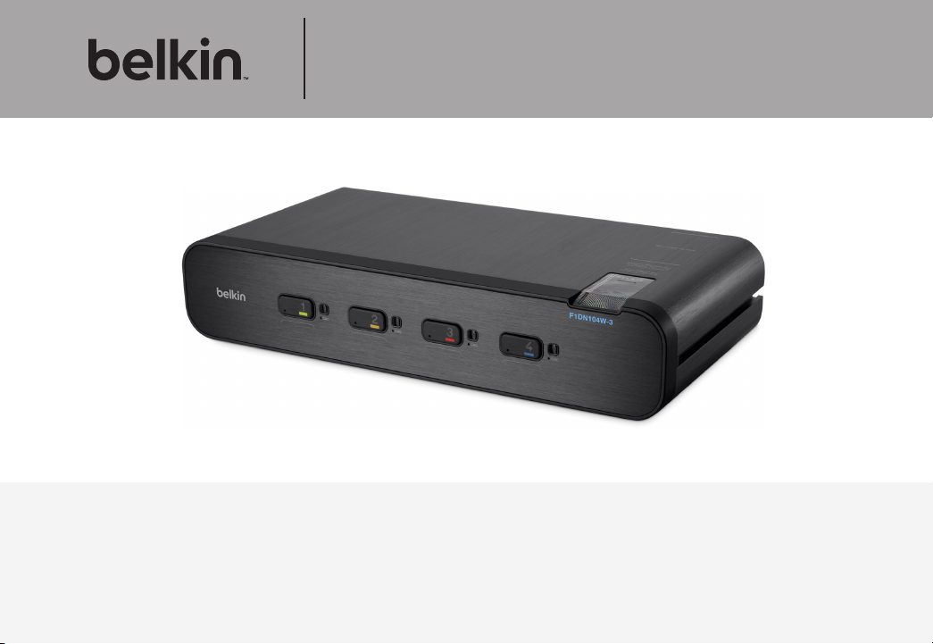
Advanced Secure DisplayPort™ KVM
User Manual
F1DN104P-3 – Advanced Secure 4-Port DisplayPort KVM, PP 3.0
F1DN104W-3 – Advanced Secure 4-Port DisplayPort Dual-Head KVM, PP 3.0
F1DN104Q-3 – Advanced Secure 4-Port Quad-Head KVM, PP 3.0
Document Number
HDC103 86 Re v.D
Page 2

TABLE OF CONTENTS
Table of Contents
Introduction ..............................................1
Package Contents.........................................1
Safety Precautions ........................................2
User Guidance & Precautions ...............................3
Overview.................................................5
Security Features .........................................5
Tamper Evident Labels .....................................6
Other Features ...........................................7
Equipment Requirements ...................................9
System Requirements ....................................10
Unit Display Diagrams ....................................11
Specifications ...........................................15
Installation . . . . . . . . . . . . . . . . . . . . . . . . . . . . . . . . . . . . . . . . . . . . . . 17
Pre-Configuration ........................................17
Connection and Installation ................................18
Color Code Chip Installation ...............................20
SECTIONS
1 2 3 4 5 6 7
Oper ating the KVM S witch ................................21
Common Access Card (CAC) Co nfigura tion and OPERATION ..22
Troubleshooting .........................................23
Information..............................................27
Belkin® Advanced Secure DisplayPort KVM
i
Page 3

INTRODUCTION
Table of Contents
Thank you for purchasing this Belkin Secure DisplayPor t KVM. This
Switch is designed for use in secure environment installations. The
Switch of fers safe centralize d control, which prevents unintended data
transfer between computers running at different security levels. The
Switch provides the highest security safeguards and features that meet
today’s Information Assurance (IA) computing requirements.
Belkin Advanced Secure DisplayPort KVM is especially challenging in
terms of security as DisplayPort is a very robust protocol by nature,
which is capable of transferring various types of information, such as
USB and Ethernet other than display. Belkin has developed this unique
Secure KVM switch with the highest possible securit y in mind, assuring
no leakage of infor mation between connected computers through any
channels including DP dedicated channels.
This User Manual provides all the details you’ll need to install and
operate your new Switch, in addition to expert troubleshooting advice—
in the unlikely event of a problem.
Reporting Belkin Product Security Vulnerability
If you are aware of potential security vulnerability while installing or
operating this product, we encourage you to contact us immediately
at the following email address: gov_security@belkin.com
Please note: Belkin Secure KVMs cannot be upgraded, serviced
or fixe d.
SECTIONS
2 3 4 5 6 71
Package Contents
• Belkin Advanced Secure DisplayPort KVM
• 12V 1.5A DC Power Supply (F1DN104P-3)
• 12V 3A DC Power Supply (F1DN104W-3, F1DN104Q-3)
• Interchangeable Port Color Chips
• Port-Naming Labels
• User Manual
Important: This product is equipped with an always-on active
anti-tamper system. Any attempt to open the enclosure may
activate the anti-tamper system and render the unit permanently
inoperable. If the unit’s enclosure appears disrupted or if all the
port LEDs flash continuously, please call Belkin Technical Support
toll-free at (800) 282-2355.
Revision
A – Initial Release, 23 Feb 2015
B – Updates to User Guidance, 26 April 2015
C – User Guidance change s, 16 June 2015
D – Correction to Features section, 13 August 2015
Belkin® Advanced Secure DisplayPort KVM
1
Page 4

INTRODUCTION
Table of Contents
SECTIONS
1
2 3 4 5 6 7
Safety Precautions
Please read the following safety precautions carefully before using the
product:
• Before cleaning, disconnect the product from any electrical power
supply.
• Do not expose the product to excessive humidity or moisture.
• Do not store or use for extensive period of time in extreme thermal
conditions – it may shorten product lifetime.
• Install the product only on a clean secure surface.
• If the product is not used for a long period of time, disconnect it
from electrical power.
• If any of the following situations occurs, have the product checked
by a qualified service technician:
– Liquid penetrates the product’s case.
– The product is exposed to excessive moisture, water or any
other liquid.
– The product is not working well even af ter carefully following
the instructions in this user’s manual.
– The product has been dropped or is physically damaged.
– The product shows obvious signs of breakage or loose internal
parts.
– In case of ex ternal power supply – If power supply overheats, is
broken or damaged, or has a damaged cable.
• The product should be stored and used only in temperature and
humidity controlled environments as defined in the product’s
environmental specifications.
• Never attempt to open the product enclosure. Any at tempt to
open the enclosure will permanently damage the product.
• The product contains a non-replaceable internal batter y. Never
attempt to replace the bat tery or open the enclosure.
• This product is e quipped with an always- on active anti-tampering
system. Any attempt to open the product enclosure will activate
the anti-tamper triggers and render the unit inoperable and
warranty void.
Belkin® Advanced Secure DisplayPort KVM
2
Page 5

INTRODUCTION
Table of Contents
SECTIONS
1
2 3 4 5 6 7
User Guidance & Precautions
Please read the following User Guidance & Precautions carefully before
using the product:
1. As product power s-up it performs a self-test procedure. In case of
self- test failure for any reason, including jammed buttons, the product
will be Inoperable. Self-test failure will be indicated by the following
abnormal LED behavior:
a. All channel-select LEDs will be turned ON and then OFF;
b. A specific, predefined LED combination will be turned ON;
c. The predefined LED combination will indicate the problem type
(jammed buttons, firmware integrity).
Try to power cycle product. If problem persists please contact your
system administrator or technical support.
2. Product power-up and RFD behavior:
a. By default, af ter product power-up, the active channel will
be computer #1, indicated by the applicable front panel push
button LED lit.
b. Product Restore-to-Factory-Default (RFD) function is available
via a physical control button on rear panel. Use a sharp obje ct
or paper clip to hold RFD button pressed for several seconds
to initiate an RFD action.
c. RFD action will be indicated by front panel LEDs blinking all
together.
d. When product boots after RFD, keyboard and mouse will be
mapped to the active channel #1 and default settings will be
restore d, erasing all user-set definitions.
3. The appropriate usage of peripherals (e.g. keyboard, mouse, display,
authentication device) is described in detail in this User Manual’s
appropriate sections. Do not connect any authentication device with
an external power source to product.
4. For security reasons products do not support wireless keyboards and
mice. In any case do not conne ct wireless keyboard /mouse to product.
5. For security reasons products do not support microphone/line-in
audio input. In any case do not connect a microphone to product audio
output port, including headsets.
6. Product is equipped with an always-on active anti-tampering system.
Any attempt to open product enclosure will activate the anti-tamper
system indicated by all channel-select LEDs flashing continuously.
In this case, product will be inoperable and warranty void. If product
enclosure appears disrupted or if all channel- select LEDs flash
continuously, please remove product from service immediately and
contact technical support.
7. In case a connected device is rejected in the console port group the
user will have the following visual indications:
a. When connecting a non-qualified keyboard, the keyboard will
be non-functional with no visible keyboard strokes on screen
when using the keyboard.
b. When connecting a non-qualified mouse, the mouse will be
non-functional with mouse cur sor frozen on screen.
c. When connecting a non-qualified display, the video diagnostic
LED will flash green and video will not work.
d. When connecting a non-qualified USB device, CAC LED will
flash green and USB device will be inoperable.
Belkin® Advanced Secure DisplayPort KVM
3
Page 6

INTRODUCTION
Table of Contents
SECTIONS
1
2 3 4 5 6 7
User Guidance & Precautions (Con.)
8. Do not connect product to computing devices:
a. That are TEMPEST computers;
b. That include telecommunication equipment;
c. That include frame grabber video cards;
d. That include special audio processing cards.
9. Important! Before re-allocating computers to channels, it is mandatory
to power cycle product, keeping it powered OFF for more than 1 minute.
10. Product log access and administrator configuration options are
described in product Administrator Guide.
11. Authentication session will be terminated once product power is down
or user intentionally terminates session.
12. If you are aware of any potential security vulnerabilit y while installing or
operating product, please remove product from ser vice immediately
and contact us in one of the ways listed in this manual.
Belkin® Advanced Secure DisplayPort KVM
4
Page 7

OVERVIEW
Table of Contents
SECTIONS
1 3 4 5 6 72
Security Features
Product is designed, manufactured and delivered in security-controlled
environments. Below is a summar y of the main advanced features
incorporated in product:
Advanced isolation between computers and shared peripherals
The emulations of keyboard, mouse and display EDID, prevent direct
contact between computers and shared peripherals. Product design
achieves maximal security by keeping the video path separate with
keyboard and mouse switched together, purging keyboard buffer when
switching channels. All these features contribute to strong isolation
between computer interfaces, maintained even when product is
powered off.
Unidirectional data flow: US B, audio and vid eo
Unique hardware architecture components prevent unauthorized data
flow, including:
• Optical unidirectional data flow diodes in the USB data path that
filtrate and reject unqualified USB devices;
• Secure analog audio diodes that prevent audio eavesdropping
with no support for microphone or any othe r audio -input device;
• Video path is kept separate from all other traffic, enforcing
unidirectional native video flow. EDID emulation is done at power
up and blocks all EDID/MCCS writes. For DisplayPort video,
filtration of AUX channel exists to reject unauthorized transactions.
Isolation of power domains
Complete isolation of power domains prevents signaling attacks.
Secure admini str ator access & log functions
Product incorporates secure administrator access and log functions to
provide auditable trail for all product security events, including battery
backup life for anti-tampering and log functions. Non-reprogrammable
firmware prevents the ability to tamper with product logic.
Always-on, act ive anti-t amper system
Active anti-tampering system prevents malicious insertion of hardware
implant such as wireles s key-logger inside product enclosure. Any antitampering attempt causes isolation of all computers and peripheral
devices rendering product inoperable and showing clear indications of
tampering event to user.
Holographic security tamper-evident labels are placed on the enclosure
to provide a clear visual indication if product has been opened or
compromised.
Metal enclosure is designed to resist mechanical tampering with all
microcontrollers protected against firmware-read, modification and
rewrite.
Belkin® Advanced Secure DisplayPort KVM
5
Page 8
OVERVIEW
12345678
Table of Contents
SECTIONS
1 3 4 5 6 72
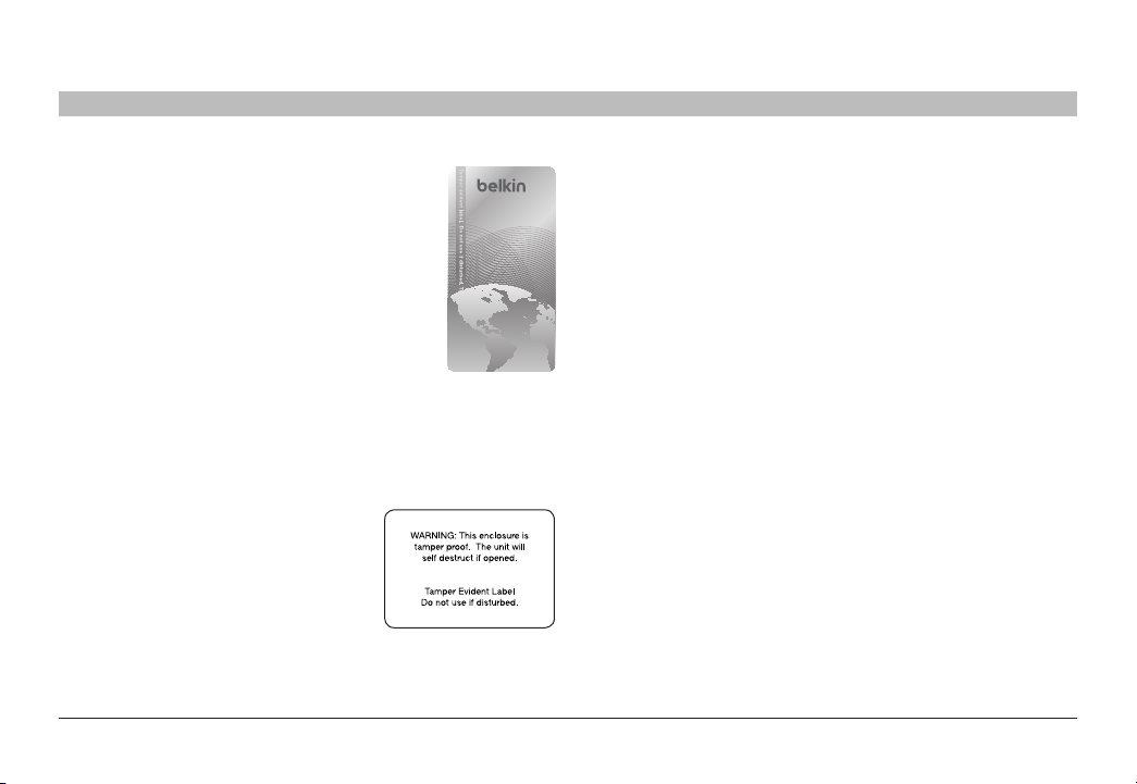
Tamper Evident Labels
Belkin Secure Switch uses holographic tamper
evident labels to provide visual indications in case
of enclosure intrusion attempt.
If for any reason the tamper evident seal is missing,
appears disrupted, or looks different than the
example shown here, please avoid using product
and call Belkin Technical Suppor t at: (80 0) 282-2355.
Active Anti-Tampering System
Belkin Secure Switch is equipped with an always-on
active anti-tampering system. If mechanical intrusion
is detected by this system, the Switch will be permanently disabled and
LED will blink continuously.
If product indication tampered state (all LEDs blinking) - please call
Technical Suppor t and avoid using that product
Product Enclosure Warning Label
Belkin Secure Switch has the following
warning printed next to the location of the
product Asset Tag and Tamper Evident
labels on product enclosure:
Belkin® Advanced Secure DisplayPort KVM
6
Page 9

OVERVIEW
Table of Contents
SECTIONS
1 3 4 5 6 7
2
Other Features
The Belkin Advanced Secure DisplayPor t KVM was designed with the
user in mind for today’s IT environment. Below is a summar y of some
features incorporated into the Switch.
Protected Display Information
Protecte d DDC/EDID emulation prevents software weaknesses that
can cause data leakage while maintaining compatibility with the
console display.
USB Device Detection
Storage and other unsafe USB devices are rejected when connected
to the Switch. Only mouse, keyboard, and CAC reader data are
passed through.
Secure Packaging
“Tear away” packaging ensures secure deliver y of the Switch as it is
routed to the end user. The recyclable packaging also breaks down flat,
simplifying the cleanup process.
USB Support
The Switch is compatible with USB technology and suppor ts
plug-and-play connectivity with USB computers, keyboards, mice, and
CAC readers.
User Display
The Belkin Advanced Secure DisplayPor t KVM is compatible with the
following types of user displays:
• HDMI capable display (console area)
• DisplayPort capable displays (computers input area)
• DVI capable displays (F1DN104Q-3 model).
HDMI and DisplayPort 1.1/1.2 ports support 4K-2K UHD resolutions of
up to 3840×2160 pixels.
DVI-I port supports up to 2560x1600 pixels (F1DN104Q-3 only).
Audio Switching
Allows you to share speakers between computers.
Belkin® Advanced Secure DisplayPort KVM
7
Page 10

OVERVIEW
Table of Contents
Port Coloring
The included color chips can be inserted into each port-selector but ton.
Colors can be as sociated with an establishe d network to facilitate port
identification and reduce user switching error.
Port Naming
The included network-name labels can be placed in the area underneath
the por t-selector button to facilitate port identification and reduce user
switching error.
LED Indicators
Each port but ton number illuminates to indicate that the console
currently controls the corresponding computer. As a port selector is
pushed, the LED number will light up.
SECTIONS
1 3 4 5 6 7
2
Integrated Mounting Rails
Integrated mounting system for easy under-desk or side-wall mounting.
USB Connectors
High-retention USB connectors keep the USB connections secure and
tight, preventing accidental disconnections.
Increased Reliability
Using a new, advanced anti-tampering battery with an extremely low
self-discharge rate the life expectancy of the switch has been
increased dramatically to over 15 years.
Belkin® Advanced Secure DisplayPort KVM
8
Page 11

OVERVIEW
Table of Contents
SECTIONS
1 3 4 5 6 7
2
Equipment Requirements
Cables
Belkin highly recommends you use Belkin DisplayPort/USB KVM Cable
Kits for your Switch to help ensure superior performance. These cables
offer the highest quality possible to ensure optimal data and video
transmission. One Cable Kit is required per connected computer.
Belkin DP to DP KVM Cable Kits w ith audio:
F1D9019b06 – 6 ft. (1.8m)
F1D9017b10 – 10 ft. (3m)
Belkin CAC USB A /B Cables
F1D9013b06 – 6 ft. (1.8m)
F1D9013b10 – 10 ft. (3m)
F1D9013b15 – 15 ft. (4.6m)
Belkin HDMI to HDMI cable
F8V3311b06-CL2 – 6 ft. (1.8m); CL-2 Rated
Belkin Smart Cables
F1D9011b06 (USB to DVI-I Smart Cable, 6’)
F1D9017b06 (DP to DVI Smart Cable, 6’)
Belkin DP to DVI Cables
F2CD002b06-E (DP to DVI)
Note: Due to USB and DisplayPort signal limitations, the cable length
cannot exceed 15 feet (4.6m), unless a USB extender is used
Belkin® Advanced Secure DisplayPort KVM
9
Page 12

OVERVIEW
Table of Contents
SECTIONS
1 3 4 5 6 7
2
System Requirements
Oper ating Systems
Product is compatible with devices running on the following operating
systems:
• Microsoft
• Red Hat
• Mac OS
USB Keyboard cons ole port
The product console USB keyboard port is compatible with Standard
USB keyboards.
Notes:
a. Console USB keyboard and mouse ports are switchable,
b. For security reasons products do not suppor t wireless
c. Non-standard keyboards, such as keyboards with inte grated
®
Windows®
®
, Ubuntu® and other Linux® platforms
®
X v10.3 and higher.
i.e. you can connect keyboard to mouse port and vice
versa. However, for optimal operation it is recommended to
connect USB keyboard to console USB keyboard port and
USB mouse to console USB mouse por t.
keyboards. In any ca se do not connect wireless keyboard
to product.
USB hubs and other USB-integrated devices, may not be
fully supported due to security policy. If they are suppor ted,
only classical keyboard (HID) operation will be functional. It
is recommended to use standard USB keyboards.
USB Mouse consol e por t
The product console USB mouse port is compatible with standard USB
mice.
Notes:
a. Console USB keyboard and mouse ports are switchable,
i.e. you can connect keyboard to mouse port and vice
versa. However, for optimal operation it is recommended to
connect USB keyboard to console USB keyboard port and
USB mouse to console USB mouse port.
b. Console USB mouse port supports Standard KVM Extender
composite device having a keyboard/mouse functions.
c. For se curity reasons products do not support wireless mice.
In any case do not connect wireles s mouse to product.
PS/2 Mouse an d Keyboard console por ts
The product console PS/2 keyboard and mouse por ts are compatible
with standard PS/2 keyboards and mice.
User Display
The console video ports are compatible with DisplayPort1.1/1.2
Belkin® Advanced Secure DisplayPort KVM
10
Page 13

OVERVIEW
Table of Contents
SECTIONS
Unit Display Diagram, Front View
(F1DN104P-3 model shown)
1 LED Indicator 3 Tamper-Evident Seal 5 Name La bel Gu ide
2 Port Selector 4
1 3 4 5 6 7
2
2 31
4 5 6
CAC Enable Switch
(F1DN104C-3 mo del onl y)
6 Color Chip
Belkin® Advanced Secure DisplayPort KVM
11
Page 14

OVERVIEW
Table of Contents
SECTIONS
Unit Display Diagram, Back View
(F1DN104P-3 model shown)
2 43 5 6 7 8 9 101
13 14 15 1611 12
1 Console USB CAC Re ader Po rt and L ED 7 Console PS/2 mouse port 13 Video Diagnostic LED
2 DCU por t (Non o perative, for f uture use) 8 Computer USB KM p ort 14 Console HDMI Port
3 Console Audio out jack 9 Computer audio port 15 Computer DP port
4 Console USB Mouse Port 10 Compute r CAC USB Por t 16 Mounting Track
5 Console USB Keyboard Port 11 Mounting Track
6 Console PS/2 keyboard port 12 DC Powe r Jack
1 3 4 5 6 7
2
Belkin® Advanced Secure DisplayPort KVM
12
Page 15

OVERVIEW
Table of Contents
SECTIONS
Unit Display Diagram, Back View
(F1DN104Q-3 model shown)
2 43 5 6 7 8 1091
13 15 17 1811 12 14 16
1 Console USB CAC Re ader Po rt and L ED 7 PS/2 Console mouse Port 13 Video Diagnostic LEDs
2 Remote c ontrol (non-o pera tive, for f uture use) 8 Comp uter US B KM por t 14 Console DVI Port
3 Console Audio Input Jack 9 Computer audio port 15 Console HDMI Ports
4 Console USB Mouse Port 10 Com puter CAC USB Por t 16 Computer DVI Port
5 Console USB Keyboard Port 11 Mounting Track 17 Computer DP Ports
6 PS/2 Console Keyboard Port 12 DC Power Jack 18 Mounting Track
1 3 4 5 6 7
2
Belkin® Advanced Secure DisplayPort KVM
13
Page 16

OVERVIEW
Table of Contents
SECTIONS
Unit Display Diagram, Back View
(F1DN104W-3 model shown)
2 43 51
13 14 15 1611 12
1 Console USB CAC Re ader Po rt and L ED 7 PS/2 Console mouse Port 13 Video Diagnostic LEDs
2 DCU por t - (non op erati ve, for fu ture use) 8
3 Console Audio Input Jack 9
4 Console USB Mouse Port 10
5 Console USB Keyboard Port 11 Mounting Track
6 PS/2 Console Keyboard Port 12 DC Power Jack
1 3 4 5 6 7
2
6 7 8 9 10
Computer USB KM p ort
Computer audio port
Computer CAC USB Po rt
14 Console HDMI Ports
15 Computer DP Por ts
16 Mounting Track
Belkin® Advanced Secure DisplayPort KVM
14
Page 17

OVERVIEW
Table of Contents
SECTIONS
1 3 4 5 6 7
2
Specifications
Part N o. F1D N10 4P- 3, F1DN 104W-3, F1D N104Q-3
Enclosure
Faceplate
Power Requirements 12V DC, 1.5A (maxi mum) powe r adapte r
AC Inpu t 100 to 240VAC
No. of Us ers S uppo rted 4
No. of Computers Supported 4
No. of mo nito rs pe r
computer supported
Video supported F1DN10 4P- 3 & F1D N104 W-3
Heavy-dut y extru ded aluminum
enclosure with metal faceplate
with cen ter-pin -posi tive pol arit y (for
F1DN104P -3 )
12V DC, 3A (max imum) powe r adapter
with cen ter-pin -posi tive pol arit y (for
F1DN104W-3 and F1DN104Q-3)
F1DN104P-3 - 1 monitor
F1DN104W-3 - 2 monito rs
F1DN104Q-3 - 4 mon itors
HDMI capable display for cons ole are a
DisplayPort capable displays for computers
input area
F1DN10 4Q -3
HDMI capable display for cons ole are a
DisplayPort and DVI-I capable displays for
computers input area
Resolution supported HDMI and Displ ayPor t 1.1/1.2 port s
Console Keyboard Port US B Type A or PS/2 Mi ni-DIN 6-pi n
Console Mouse Port USB Type A or P S/2 Mini -DIN 6 -pin
Console CAC Input USB Type A
Console Monitor Port 1 x HD MI1.4 female c onnector
Console Speaker 1/8" (3.5mm) fe male
CPU Keyb oard/Mo use Po rts USB Type B
CPU CAC Por ts USB Type B
CPU Keyb oard/Mo use Po rts USB Type B
CPU Aud io 1/8" (3.5mm) fe male
support 4K-2K UHD r esolu tions o f up
to 3840×2160 p ixels.
DVI-I port su ppor ts up to 256 0x1600
pixels (F1DN104Q-3 only).
female connector
female connector
(F1D N10 4P- 3)
2 x HDMI1.4 femal e connector
(F1D N10 4W- 3)
3 x HDMI1.4 femal e connector & 1 x
DVI-I female connector(F1DN104Q-3)
Belkin® Advanced Secure DisplayPort KVM
15
Page 18

OVERVIEW
Table of Contents
CPU Monitor Ports
Port Selectors
LED Indicators
User C hann el Se lect ion M ethods
Operating Temp
Storage Temp
Humidity
Dimensions F1D N104P- 3
SECTIONS
1 x DisplayPort 1.1/1.2 female
connector (F1DN104P-3)
2 x DisplayPort 1.1/1.2 female
connector (F1DN104W-3)
3 x DisplayPort 1.1/1.2 female
conne ctor & 1 x DVI -I fema le
connector(F1DN104Q-3)
4
4
Front-panel push buttons
32° to 104° F (0° to 40 ° C)
-4° to 140° F (-20° to 60° C)
0-80% RH, non-condensing
12.5 (W) x 1.7 (H) x 6. 4 (L) inches /
317.5 (W) x 4 3.2 (H) x 162.6(L) mm
F1DN10 4W- 3
12.5 (W) x 2.5 (H)x 6.4 (L) inche s/
317.5 (W) x 6 3.5 (H)x 162.6(L) mm
F1DN10 4Q -3
12.5 (W) x 3.8 (H)x 6.4 ( L) inch es/
317.5 (W) x 9 6.5 (H) x 162.6(L) mm
1 3 4 5 6 7
2
Weight F1DN104P -3
Made i n Designed in California. Assembled in
Product Life-Cycle 5 years
Warranty 3 years
F1DN104W -3
F1DN104Q- 3
US with US a nd Forei gn components.
3.9 lbs.(1.77kg)
4.85 lbs.(2.2kg)
5.85 lbs .(5.65kg)
Belkin® Advanced Secure DisplayPort KVM
16
Page 19

INSTALLATION
Table of Contents
SECTIONS
1 2 4 5 6 73
Pre-Configuration
Wher e to place the Switch:
The enclosure of the Switch is designed for desktop or rack-mount
configuration. Rack-mount brackets are included with the Switch.
Consider the following when deciding where to place the Switch:
• Your proximity to the por t selectors on the front of the Switch
• The lengths of the cables attached to your keyboard, monitor,
and mouse
• The location of your computers in relation to your console
• The lengths of the cables you use to connect your computers to
the Switch
Warning: Avoid placing cables near fluorescent lights,
air-conditioning equipment, or machines that create electrical noise
(e.g., vacuum cleaners).
Important:
1. If the unit’s enclosure appears disrupte d or if all channelselect LEDs flash continuously, please remove product from
service immediately and contact Belkin Technical Suppor t
at (800) 282-2355.
2. Do not connect product to computing devices:
a. That are TEMPEST computers;
b. That include telecommunication equipment;
c. That include frame grabber video cards;
d. That include special audio processing cards.
Belkin® Advanced Secure DisplayPort KVM
17
Page 20

INSTALLATION
Table of Contents
SECTIONS
1 2 4 5 6 7
Connection and Installation
Important: As the unit powers up it per forms a self-test proce dure. In
case the self- test has faile d for any reason the product LED behavior
will be abnormal as described in User Guidance section. Try to
power cycle the unit. If problem persists please contact your system
administrator or Technical Support.
Step 1 – Conne cti ng the Console to t he Sw itch
Warning: Before attempting to connect anything to the Switch or your
computers, please ensure that all computer equipment and devices are
powered off.
Connect your monitor, keyboard, mouse, and speaker to the rear of the
Switch in the “User Console” section.
3
Notes:
1. Console USB keyboard and mouse ports are switchable, i.e.
you can connect keyboard to mouse port and vice versa.
However, for optimal operation it is recommended to connect
USB keyboard to console USB keyboard port and USB mouse to
console USB mouse por t.
2. For se curity reasons products do not support wireless keyboards.
In any case do not connect wireles s keyboard to product.
3. Non-standard keyboards, such as keyboards with inte grated
USB hubs and other USB-integrate d devices, may not be
fully supported due to se curity policy. If they are supported,
only classical keyboard (HID) operation will be functional. It is
recommended to use standard USB keyboards.
4. Console USB mouse port supports Standard KVM Extender
composite device having a keyboard/mouse functions.
Step 2 – Power Up
2.1 Turn the monitor on.
2.2 Power up the Belkin Advanced Secure DisplayPort K VM by
connecting the power. The display diagnostic LED should be solid
green a few seconds after power up. This indicates the display EDID
information has been captured and secured.
Belkin® Advanced Secure DisplayPort KVM
18
Page 21

INSTALLATION
Table of Contents
Step 3 – Connecting the Computers
3.1 Using USB cables, connect each computer to the USB port in
“compute r inter face ports” area on product.
3.2 If computer uses audio output, e.g. speakers/headphones, connect
audio cable from its audio output port to the corresponding audio
input port on product.
3.3 If the computer uses a smar t card /CAC reader, connect a USB
cable between the CAC-enabled computer and the corresponding
CAC port on product.
Note:
1. If the number of product channels is larger than the number of
source s used, make sure the computers are conne cted in a row
starting from computer #1. For example, if there are 3 channels
used, connect computers to channels #1, #2 and then #3.
2. The USB cable must be connected dire ctly to a free USB port
on the computer, with no USB hubs or other devices in between.
SECTIONS
1 2 4 5 6 7
3
Step 4 – Powering Up the Computers
Power up all the attached computer s and check for display
and peripheral functionality. All computers can be powered on
simultaneously.
Note: Your computers should recognize the Switch and automatically
install the HID USB driver if necessar y.
When you power on your computers, the Switch emulates both a mouse
and keyboard on each port and allows your computers to boot normally.
The computer connected to por t “1” will be displayed on the monitor.
Check to se e that the keyboard, monitor, and mouse are working
normally. Proceed to do this with all occupied ports to verif y that all
computers are connected and responding correctly. If you encounter
an error, check your cable connections for that computer and reboot.
If the problem persists, please refer to the Troubleshooting section in
this User Manual.
Belkin® Advanced Secure DisplayPort KVM
19
Page 22

INSTALLATION
Table of Contents
SECTIONS
1 2 4 5 6 7
Color Code Chip Installation
The Belkin Advanced Secure DisplayPor t KVM’s port-selector buttons
can be color-coded for easier identification. Refer to the installation
instructions below.
Note: You may have to remove the existing black color chip first.
Insert color chip R emove co lor chip with
a standard paperclip
3
Port Name Label
The included network-name and blank labels can be placed in the area
underneath the port-selector buttons for port identification.
Please note that the default port at power-up is port 1. In case of
a power failure or if the power is cycled, the switch will default to port 1.
Belkin® Advanced Secure DisplayPort KVM
20
Page 23

OPERATING THE KVM SWITCH
Table of Contents
SECTIONS
1 2 3 5 6 74
Selecting a Computer Using Port Selectors
Self-Test Procedure:
As product power s-up it performs a self-test procedure. In case of
self- test failure for any reason, including jammed buttons, the product
will be Inoperable. Self-test failure will be indicated by the following
abnormal LED behavior:
• All channel-select LEDs will be turne d ON and then OFF;
• A specific, predefined LED combination will be turned ON;
• The predefined LED combination will indicate the problem type
(jammed buttons, firmware integrity).
Try to power cycle product. If problem persists please contact your
system administrator or technical support.
Now that product, computers and peripherals are connected and
powered up, it is ready for use.
Now that you have connected your console and computers to the
Switch, it is ready for use. You can select which computer you wish to
control by pressing the corresponding port selector on the front of the
Switch. The LED number will illuminate to indicate which computer (or
port) is curre ntly selected. It may take approximately 1 second for the
video signal to sync after switching ports. This is normal behavior and
is dependent on the display connected. This is normal operation and
ensures that proper synchronization is established between the monitor
and the connected computers.
Keyboard and mouse inputs can only be sent to the selected computer,
and video outputs can only be received from the selected computer. The
Switch also prevents any data transfer bet ween connected computers,
ensuring the securit y of your computers.
Please note that the default port at power-up is port 1. In case of a
power failure or if the power is cycled, the Switch will default to port 1.
Belkin® Advanced Secure DisplayPort KVM
21
Page 24

COMMON ACCESS CARD (CAC) CONFIGURATION AND OPERATION
Table of Contents
CAC connection to the compute r requires a separate USB cable
connection and allows the user to specif y whether there is a CAC
required for that computer or not. This allows the CAC to be connected
and controlled separately to the keyboard, mouse, video and audio.
SECTIONS
1 2 3 4 6 75
Step 1 – Installation
1.1 Using the included USB cable, connect one end of the cable to the
computer that requires CAC, and the other end to the CAC port on
the Belkin Advanced Secure DisplayPor t KVM that corresponds to
the computer.
1.2 Enable CAC for the same port connection in Step 1.1 by switching
the CAC switch to the right.
1.3 Repeat steps above for additional computers that require CAC.
Note: Make sure that the CAC switch is disabled (left) for all other
non-connected CAC systems.
1.4 Once configured, the CAC connection will be switched only when
required by the connected computer. When switching from a CAC
enable d port to a non-CAC enabled por t, the CAC connection will
remain with the last previously selected port where the CAC was
set to enable.
Belkin® Advanced Secure DisplayPort KVM
22
Page 25

TROUBLESHOOTING
Table of Contents
SECTIONS
1 2 3 4 5 76
General
As product powers-up all channel-select LEDs are turned ON and
then OFF. After that a s pecific, predefined LED combination is
turned ON. Product is inoperable.
• The product did not pass self-test procedure. Try to powe r
cycle product. If problem persists please contact your system
administrator or our technical support.
My compute r does not boot when connected to the Switch but
works fine wh en I connect my keyboard, video, an d mouse dir ect ly
to my computer.
• Make sure that the DP/USB KVM Cable Kit is connected tightly
between the Switch and the computer.
The Switch d oes not turn on.
• Ensure that the AC power cord is securely connected to both the
AC inlet and to the wall outlet.
• Check that the power switch is in the ON position.
The Switch m akes rapid c licking noise s and t he port LEDs fla sh
continuously when turned on.
• If the clicking noises continue, the unit may have been tampered
with or experienced seve re impact.
NOTE: This Switch is equipped with ac tive anti-tamper triggers. Any
attempt to open the enclosure will activate the anti-tamper triggers
and render the unit inoperable. If the unit’s enclosure appears
disrupted or if all the por t LEDs flash continuously, please call Belkin
Technical Suppor t at (800) 282-2355.
Belkin® Advanced Secure DisplayPort KVM
23
Page 26

TROUBLESHOOTING
Table of Contents
SECTIONS
1 2 3 4 5 7
Video
I am get tin g ghos tin g, shadowing, or fuzzy ima ges on my monitor.
• Check that all video cables are inser ted properly to the Switch,
computer, and monitor.
• With ever ything connected, power-cycle the Belkin Advanced
Secure DisplayPort K VM to reset the video.
• Make sure the Video Diagnostic LED is solid green.
• Check that the monitor you are using suppor ts the re solution and
refresh-rate setting on your computer.
• Lower the video resolution of your monitor.
• Check that the video-cable length does not exceed 15 feet (4.6m).
• Check that the graphics card you are using supports the resolution
and refresh-rate setting on your computer.
• Connect the monitor dire ctly into the computer you are having
trouble with to see if the problem still appears.
• Do not use video splitters.
6
I am get tin g a blank scr een on my monitor.
• Ensure that the power switch is in the ON position.
• Check that the display is turned on
• Check that the cables are connected, and check that the display
input is DisplayPort
• Check that all video cables are inserted properly.
• Ensure that the power cord is inser ted securely to the AC inlet.
• Connect your monitor directly to the computer to verify that your
monitor is functioning properly.
• Reboot the computer.
• Try a different video cable.
• Try a different monitor.
• Ensure to download the latest display drivers.
I have difficulty inser tin g a Display Port cable into the Switch.
• Check that the connectors are not bent or damaged.
• Check if the contacts on the Switch DisplayPort connectors are
not bent or damaged.
Belkin® Advanced Secure DisplayPort KVM
24
Page 27

TROUBLESHOOTING
Table of Contents
SECTIONS
1 2 3 4 5 7
Keyboard
The comput er does not detect my keyboard, or my keyboar d does
not work when I switc h computers or reboot.
• Check that the keyboard you are using is connected properly to
the Switch, in the USB port labeled “Keyboa rd.”
• Check that the USB cable between the Switch and the computer
is completely connected.
• Try connecting to a different USB port on the computer.
• Make sure the keyboard works when directly plugged into the
computer (the HID USB driver is installed on the computer).
Rebooting may be necessary when tr ying this.
• Make sure you are not using a keyboard with an integrated USB
hub or other USB-integrated devices.
• If the computer is coming out of standby mode, allow up to one
minute to regain mouse function.
• Try a different keyboard.
• Do not use a USB extension cable.
The CAPS, NUM, and Scroll Lock light s on my keyboar d do
not function when I con nect to the Belkin Advanced Secure
DisplayPort KVM.
This is normal operation. The lock-state information is fully functional.
Due to the se curity of the Belkin Advanced Secure DisplayPort K VM and
known exploitation of lock-state information for leakages, the LED status
is not supporte d. Please refer to the operating system for verification of
the lock-state information for CAPS, NUM, and Scroll Lock.
6
Mouse
The computer doe s not detect my mous e, or my mouse does not
work wh en I swi tch computers or reboot.
• Check that the mouse you are using is connected properly to the
Switch in the USB port labeled “Mouse.”
• Check that the USB cable between the Switch and the computer
is completely connected.
• Try connecting to a different USB port on the computer.
• Make sure the mouse works when directly plugged into the
computer (the HID USB driver is installed on the computer).
Rebooting may be necessary when tr ying this.
• If the computer is coming out of standby mode, allow up to one
minute to regain mouse function.
• Try a different mouse.
Belkin® Advanced Secure DisplayPort KVM
25
Page 28

TROUBLESHOOTING
Table of Contents
SECTIONS
1 2 3 4 5 7
CAC Related Faults
The CAC reader is not funct ioning.
• Check to see if the LED is illuminated for the CAC reader.
• Confirm that the CAC reader switch on the Belkin Advanced
Secure DisplayPort K VM is properly set to the ON position.
• Try using the CAC reader on a different K VM channel.
• Try a different CAC reader.
Important Security Note:
If you are aware of potential security vulnerability while installing or
operating this product, we encourage you to contact us immediately
at the following email address: gov_security@belkin.com
The gov_security@belkin.com email address is not intended to
reach technical support on Belkin products or ser vices.
6
Belkin® Advanced Secure DisplayPort KVM
26
Page 29

INFORMATION
Table of Contents
SECTIONS
1 2 3 4 5 6 7
FCC Statement
DECLARATION OF CONFORMITY WITH FCC RULES FOR
ELECTROMAGNETIC COMPATIBILITY
We, Belkin International, Inc., of 12045 E. Waterfront Drive, Playa
Vista, CA 90094, declare under our sole responsibility that the
products comply with Part 15 of the FCC Rules. Operation is subject
to the following two conditions: (1) this device may not cause harmful
interference, and (2) this device must accept any interference received,
including inter ference that may cause undesired operation.
CE Declaration of Conformity
We, Belkin International, Inc., declare under our sole responsibility that
the products are in conformity with Emissions Standard EN55022 and
with Immunity Standard EN55024, LVP EN61000-3-2, and EN610003-3.
ICES
This Class B digital apparatus complies with Canadian ICES-003. Cet
appareil numérique de la classe B est conforme á la norme NMB-003
du Canada.
Belkin International, Inc., Limited 3-Year Product Warranty
What t his wa rra nty covers.
Belkin International, Inc. (“Belkin”) warrants to the original purchaser of
this Belkin product that the product shall be free of defects in design,
assembly, material, or workmanship.
What t he period of cover age is.
Belkin warrants the Belkin product for three years.
What will we do to correct prob lems?
Product Warranty.
Belkin will repair or replace, at its option, any defective product free of
charge (except for shipping charges for the product). Belkin reser ves
the right to discontinue any of its products without notice, and disclaims
any limited warranty to repair or replace any such discontinued
products. In the event that Belkin is unable to repair or replace the
produc t (for example, because it has been discontinued), Belkin will
offer either a refund or a credit toward the purchase of another product
from Belkin.com in an amount equal to the purchase price of the
product as evidenced on the original purchase receipt as discounted
by its natural use.
Belkin® Advanced Secure DisplayPort KVM
27
Page 30

INFORMATION
Table of Contents
What is not covered by this warrant y?
All above warranties are null and void if the Belkin product is not
provided to Belkin for inspection upon Belkin’s request at the sole
expense of the purchaser, or if Belkin determines that the Belkin
product has been improperly installed, altered in any way, or
tampered with. The Belkin Product Warranty does not protect against
acts of God such as flood, lightning, earthquake, war, vandalism,
theft, normal-use wear and tear, erosion, depletion, obsolescence,
abuse, damage due to low voltage disturbances (i.e. brownouts or
sags), non-authorized program, or system equipment modification
or alteration.
How to get service.
To get service for your Belkin product you must take the
following steps:
1. Contact Belkin International, Inc., at 12045 E. Water front
Drive, Playa Vista, CA 90094, Attn: Customer Service, or call
(800)-282-2355, within 15 days of the Occurrence. Be
prepared to provide the following information:
a. The part number of the Belkin product.
b. Where you purchased the product.
c. When you purchased the product.
d. Copy of original receipt.
SECTIONS
1 2 3 4 5 6
7
2. Your Belkin Customer Service Representative will then instruct
you on how to for ward your receipt and Belkin product and how to
proceed with your claim.
Belkin reser ves the right to review the damaged Belkin product. All costs
of shipping the Belkin product to Belkin for inspection shall be borne
solely by the purchaser. If Belkin determines, in its sole discretion, that
it is impractical to ship the damaged equipment to Belkin, Belkin may
designate, in its sole discretion, an equipment repair facility to inspect
and estimate the cost to repair such equipment. The cost, if any, of
shipping the equipment to and from such repair facility and of such
estimate shall be borne solely by the purchaser. Damaged equipment
must remain available for inspection until the claim is finalized.
Whenever claims are set tled, Belkin reser ves the right to be subrogated
under any existing insurance policies the purchaser may have.
Belkin® Advanced Secure DisplayPort KVM
28
Page 31

INFORMATION
Table of Contents
How state law r elates to t he war ranty.
THIS WARR ANT Y CONTAINS THE SOLE WARRANTY OF BELKIN.
THERE ARE NO OTHER WARRANTIES, EXPRESSED OR, EXCEPT AS
REQUIRED BY LAW, IMPLIED, INCLUDING THE IMPLIED WARRANTY
OR CONDITION OF QUALIT Y, MERCHANTABILITY OR FITNESS FOR A
PARTICUL AR PURPOSE, AND SUCH IMPLIED WARRANTIES, IF ANY,
ARE LIMITED IN DUR ATION TO THE TERM OF THIS WARRANTY.
Some states do not allow limitations on how long an implied warranty
lasts, so the above limitations may not apply to you.
IN NO EVENT SHALL BELKIN BE LIABLE FOR INCIDENTAL, SPECIAL,
DIRECT, INDIRECT, CONSEQUENTIAL OR MULTIPLE DAMAGES SUCH
AS, BUT NOT LIMITED TO, LOST BUSINESS OR PROFITS ARISING
OUT OF THE SALE OR USE OF ANY BELKIN PRODUCT, EVEN IF
ADVISED OF THE POSSIBILITY OF SUCH DAMAGES.
This warranty gives you specific legal rights, and you may also have
other rights, which may vary from state to state. Some states do not
allow the exclusion or limitation of incidental, consequential, or other
damages, so the above limitations may not apply to you.
SECTIONS
1 2 3 4 5 6
7
Belkin® Advanced Secure DisplayPort KVM
29
Page 32

INFORMATION
Table of Contents
SECTIONS
1 2 3 4 5 6
Reporting Belkin Product Security Vulnerability
If you are aware of potential security vulnerability with any Belkin
Government product, we encourage you to contact us immediately
at the following email address: gov_security@belkin.com or our
technical support line at: 1-800-282-2355.
After your communication is received, Belkin Government personnel will
contact you to follow up. To ensure confidentiality, Belkin encourages
you to use our PGP encryption key.
The gov_security@belkin.com email address is not intended to reach
technical support on Belkin Government products or services.
7
Belkin® Advanced Secure DisplayPort KVM
30
Page 33

belkinbusiness.com
© 2015 Belkin In terna tional, Inc. All r ights r eser ved. A ll trade n ames a re regi stere d trade marks o f respe ctive manufacturers
listed. Windows and Win dows Vis ta are either registe red tr adema rks or tr ademarks of Mi crosoft Corpora tion in the Unite d
States a nd/or other cou ntrie s. Mac OS i s a trade mark of A pple In c., regi stere d in the U.S. a nd othe r countries.
 Loading...