

Page 1
Secure 4/8 port KM Switch
User Manual
Models:
F1DN104K-3 – Advanced Secure 4-Port Keyboard / Mouse (KM) Switch, PP PSS 3.0
F1DN108K-3 – Advanced Secure 8-Port Keyboard / Mouse (KM) Switch, PP PSS 3.0
Document Number
HDC103 89 Re v.D
Page 2

TABLE OF CONTENTS
Table of Contents
Introduction ..............................................1
What is a KM (Keyboard / Mouse) Switch? .....................1
Package Contents.........................................2
Overview.................................................3
Safety Precautions ........................................3
User Guidance & Precautions ...............................4
Security Features .........................................6
Tamper Evident Labels .....................................7
Operational Features ......................................8
What is Seamless Cursor Switching? .........................9
Equipment Requirements ..................................10
Belkin Secure KM Features ................................13
Product Specifications ....................................15
Installation . . . . . . . . . . . . . . . . . . . . . . . . . . . . . . . . . . . . . . . . . . . . . . 16
Before Installation........................................16
Connection and Installation ................................17
Advance d Setup .........................................21
SECTIONS
1 2 3 4 5 6 7
Operation ...............................................24
Operating the Secure KM Switch ............................24
Troubleshooting .........................................26
Keyboard ...............................................26
Video ..................................................27
Mouse .................................................27
Appendices .............................................28
APPENDIX A – Secure KM Configuration
Utility Software (KMC Creator)..............................28
APPENDIX B – Secure KM Configuration
Utility (KMC Loader) Software ..............................35
Information..............................................38
Belkin® Secur e 4/8 port KM S witch User Ma nual
i
Page 3

INTRODUCTION
Table of Contents
Thank you for purchasing this Belkin Advanced Secure Keyboard/Mouse
(K/M) Switch. This KM Switch is designed for use in secure environments
across wide security gaps. This product provides the highest security
safeguards and features, meeting cur rent and future cyber prevention
requirements.
This User Manual provides all the details you’ll need to install and operate
your new product, and also to troubleshoot it in the unlikely event of a
problem.
SECTIONS
2 3 4 5 6 71
What is a KM (Keyboard / Mouse) Switch?
There are many cases where one user needs to work simultaneously with
more than one computer. In some cases users have multiple displays
attached to multiple computers. The challenge is how a single user can
interact with multiple computers with multiple displays each. K VMs are not
suitable for these users as they are designed to switch displays; allowing
the user to only see and manage one target device at a given time. Using the
Belkin Secure KM users can see all the connected computers at the same
time and easily decide on which computer he wants to work.
A KM switch is a device that switches a single keyboard and mouse bet ween
multiple computers. A KM switch is essentially a KVM switch without the
video switching - all displays are continuously connected to their re spective
computers; so that all connected device can be managed seamlessly, in
real time. Multiply displays can be connected to each computer that is
connected to the Belkin Secure KM. The Belkin Secure KM is designed
to have up to 8 computers connected and working simultaneously in any
possible monitor setup. The configuration of the Belkin Secure KM can be
done by using the KM presets or by using the easy to use configuration tool.
The Belkin Secure KM supports Windows, Linux and Mac operating
systems. Switching is done simply by dragging your mouse from one
window to another having it disappearing from one machine and appearing
on another. Multi Displays connected to the same computers are only
suppor ted by Windows based operating systems.
Belkin® Secur e 4/8 port KM S witch User Ma nual
1
Page 4

INTRODUCTION
Table of Contents
SECTIONS
Package Contents
• Belkin Advanced Secure KM Switch
• 12V 1.5A DC Power Supply (F1DN104K-3 only)
• AC Power Cord (F1DN108K-3 only)
• Interchangeable Port Color Chips
• Port-Naming Labels
• Belkin USB configuration cable
• User Manual
1
2 3 4 5 6 7
Important: This product is equipped with an always-on active
anti-tamper system. Any attempt to open the enclosure may
activate the anti-tamper system and render the unit permanently
inoperable. If the unit’s enclosure appe ars disrupted or if all the
port LEDs flash continuously, please call Belkin Technical Support
toll-free at (800) 282-2355.
Please note: Belkin Secure KM Products cannot be upgraded, ser viced
or fixe d.
Important Security Note: If you are aware of potential securit y vulnerability
while installing or operating this product, we encourage you to contact us
immediately at the following email address: gov_security@belkin.com
Revision
A – Initial Release, 23 Feb 2015
B – Updates to User Guidance, 26 April 2015
C – User Guidance change s, 16 June 2015
D – Correction to Features section, 13 August 2015
Belkin® Secur e 4/8 port KM S witch User Ma nual
2
Page 5

OVERVIEW
Table of Contents
SECTIONS
1 3 4 5 6 72
Safety Precautions
Please read the following safety precautions carefully before using the
product:
• Before cleaning, disconnect the product from any electrical power
supply.
• Do not expose the product to excessive humidity or moisture.
• Do not store or use for extensive period of time in extreme thermal
conditions – it may shorten product lifetime.
• Install the product only on a clean secure surface.
• If the product is not used for a long period of time, disconnec t it from
electrical power.
• If any of the following situations occurs, have the product checked by
a qualified service technician:
– Liquid penetrates the product’s case.
– The product is exposed to excessive moisture, water or any other
liquid.
– The product is not working well even after carefully following the
instructions in this user’s manual.
– The product has been dropped or is physically damaged.
– The product shows obvious signs of breakage or loose internal
parts.
– In case of ex ternal power supply – If power supply overheats, is
broken or damaged, or has a damaged cable.
• The product should be stored and used only in temperature and
humidit y controlled environments as defined in the product’s
environmental specifications.
• Never attempt to open the product enclosure. Any at tempt to open
the enclosure will permanently damage the product.
• The product contains a non-replaceable internal battery. Never
attempt to replace the bat tery or open the enclosure.
• This product is e quipped with an always-on active anti-tampering
system. Any attempt to open the product enclosure will activate the
anti-tamper trigger s and render the unit inoperable and warranty void.
Belkin® Secur e 4/8 port KM S witch User Ma nual
3
Page 6

OVERVIEW
Table of Contents
SECTIONS
1 3 4 5 6 7
2
User Guidance & Precautions
Please read the following User Guidance & Precautions carefully before
using the product:
1. As product powers-up it performs a self-test procedure. In case of
self- test failure for any reason, including jammed buttons, the product
will be Inoperable. Self-test failure will be indicated by the following
abnormal LED behavior:
a. All channel-select LEDs will be turned ON and then OFF;
b. A specific, predefined LED combination will be turned ON;
c. The predefined LED combination will indicate the problem type
(jammed buttons, firmware integrity).
Try to power cycle product. If problem persists please contact your
system administrator or technical support.
2. Product power-up and RFD behavior:
a. By default, after product power-up, the active channel will be
computer #1, indicated by the applicable front panel push button
LED lit.
b. Product Restore-to-Factory-Default (RFD) function is available
via a physical control button on rear panel. Use a sharp object
or paper clip to hold RFD button pressed for several seconds to
initiate an RFD action.
c. RFD action will be indicated by front panel LEDs blinking all
together.
d. When product boots after RFD, keyboard and mouse will be
mapped to the active channel #1 and default settings will be
restore d, erasing all user-set definitions.
3. The appropriate usage of peripherals (e.g. keyboard, mouse, display,
authentication device) is described in detail in this User Manual’s
appropriate sections. Do not connect any authentication device with
an external power source to product.
4. For security reasons products do not suppor t wireless keyboards and
mice. In any case do not connect wireless keyboard/mouse to product.
5. For security reasons products do not suppor t microphone/line -in
audio input. In any case do not connect a microphone to product audio
output port, including headsets.
6. Product is equipped with an always-on active anti-tampering system.
Any attempt to open product enclosure will activate the anti-tamper
system indicated by all channel-select LEDs flashing continuously.
In this case, product will be inoperable and warranty void. If product
enclosure appears disrupted or if all channel- select LEDs flash
continuously, please remove product from service immediately and
contact technical support.
7. In case a connected device is rejected in the console por t group the
user will have the following visual indications:
a. When connecting a non-qualified keyboard, the keyboard will be
non-functional with no visible keyboard strokes on screen when
using the keyboard.
b. When connecting a non-qualified mouse, the mouse will be non-
functional with mouse cursor frozen on screen.
c. When connecting a non-qualified display, the video diagnostic LED
will flash green and video will not work.
d. When connecting a non-qualified USB device, CAC LED will flash
green and USB device will be inoperable.
Belkin® Secur e 4/8 port KM S witch User Ma nual
4
Page 7

OVERVIEW
Table of Contents
SECTIONS
1 3 4 5 6 7
2
User Guidance & Precautions (Con.)
8. Do not connect product to computing devices:
a. That are TEMPEST computers;
b. That include telecommunication equipment;
c. That include frame grabber video cards;
d. That include special audio processing cards.
9. Important! Before re-allocating computers to channels, it is mandator y
to power cycle produc t, keeping it powered OFF for more than 1
minute.
10. Product log access and administrator configuration options are
described in product Administrator Guide.
11. Authentication session will be terminated once product power is down
or user intentionally terminates session.
12. If you are aware of any potential security vulnerability while installing or
operating product, please remove product from service immediately
and contact us in one of the ways listed in this manual.
Belkin® Secur e 4/8 port KM S witch User Ma nual
5
Page 8

OVERVIEW
Table of Contents
SECTIONS
1 3 4 5 6 7
2
Security Features
Product is designed, manufactured and delivered in security-controlled
environments. Below is a summar y of the main advanced features
incorporated in product:
Advanced isolation between computers and shared peripherals
The emulations of keyboard, mouse and display EDID, prevent direct
contact between computers and shared peripherals. Product design
achieves maximal security by keeping the video path separate with
keyboard and mouse switched together, purging keyboard buffer when
switching channels. All these features contribute to strong isolation between
computer inter faces, maintained even when product is powered off.
Unidirectional data flow: US B, audio and vid eo
Unique hardware architecture components prevent unauthorized data flow,
including:
• Optical unidirectional data flow diodes in the USB data path that
filtrate and reject unqualified USB devices;
• Secure analog audio diodes that prevent audio eavesdropping with
no support for microphone or any other audio-input device;
• Video path is kept separate from all other traffic, enforcing
unidirectional native video flow. EDID emulation is done at power up
and blocks all EDID/MCCS writes. For DisplayPort video, filtration of
AUX channel exists to reject unauthorized transactions.
Isolation of power domains
Complete isolation of power domains prevents signaling attacks.
Secure admini str ator access & log funct ions
Product incorporates secure administrator access and log functions to
provide auditable trail for all product se curity events, including battery
backup life for anti-tampering and log functions. Non-reprogrammable
firmware prevents the ability to tamper with product logic.
Always-on, act ive anti-t amper system
Active anti-tampering system prevents malicious inser tion of hardware
implant such as wireless key-logger inside product enclosure. Any antitampering attempt causes isolation of all computers and peripheral devices
rendering product inoperable and showing clear indications of tampering
event to user.
Holographic security tamper-evident labels are placed on the enclosure
to provide a clear visual indication if product has been opened or
compromised.
Metal enclosure is designed to resist mechanical tampering with all
microcontrollers protected against firmware-read, modification and rewrite.
Belkin® Secur e 4/8 port KM S witch User Ma nual
6
Page 9

OVERVIEW
12345678
Table of Contents
Secure Packaging
“Tear away” packaging ensures secure deliver y of the Switch as it is routed
to the end user. The recyclable packaging also breaks down flat, simplifying
the cleanup process.
LED Indicators
Each port but ton number illuminates to indicate that the console curre ntly
controls the cor responding computer. As a port selector is pushed, or if the
mouse cursor crosses betwe en displays associated to different computers
or networks, the LED number will light up.
SECTIONS
1 3 4 5 6 7
2
Tamper Evident Labels
Belkin Secure Switch uses holographic tamper evident
labels to provide visual indications in case of enclosure
intrusion attempt.
If for any reason the tamper evident seal is missing,
appears disr upted, or looks different than the
example shown here, please avoid using product and
call Belkin Technical Support at: (800) 282-2355.
Active Anti-Tampering System
Belkin Secure Switch is equipped with an always- on
active anti-tampering system. If mechanical intrusion is
detected by this system, the Switch will be permanently disabled and LED
will blink continuously.
If product indication tampered state (all LEDs blinking) - please call
Technical Suppor t and avoid using that product
Product Enclosure Warning Label
Belkin Secure Switch has the following
warning printed next to the location of the
product Asset Tag and Tamper Evident labels
on product enclosure:
Belkin® Secur e 4/8 port KM S witch User Ma nual
7
Page 10

OVERVIEW
Table of Contents
SECTIONS
1 3 4 5 6 7
2
Operational Features
The Belkin Secure KM was designed with the user in mind for today’s
IT environment. Below is a summar y of some key operational features
incorporated into the Product.
Supp ort for multiple head
The Belkin Secure KM can be easily configured to support dual, triple and
up to 16 head computers through a signed software driver. Note that single
head installation does not need any software installation.
Seamless Cursor Switching (SCS)
SCS allows the Belkin Secure KM to switch automatically between
computers once mouse cursor crosses display borders. The switching is
seamless between multiple computers with cursor movement.
Extensive setup options
System mode provides many customized set tings, which includes display
arrangement, monitor size, cursor speed and mouse acceleration. Please
contact Belkin for the KM Creator and KM Loader customization sof tware.
Integrated Mounting Rails
The Belkin Secure KM features an integrated mounting system for easy
under-the-desk, or side-wall mounting.
Audio Support
The Belkin Secure KM supports audio out switching. Microphone switching
is not supporte d to prevent analog leakages through audio ports.
Port Coloring
The included color chips can be inserted into each por t-selector button.
Colors can be associated with an established network to facilitate port
identification and reduce user switching error.
Port Naming
The included network-name labels can be placed in the area underneath
the port-selector but ton to facilitate port identification and reduce user
switching error. Blank labels are also provided for network names that are
not listed on the included network-name labels.
Increased Reliability
Using a new, advanced anti-tampering battery with extremely low selfdischarge rate the life expectancy of the switch has been increased
dramatically to over 25 years.
Belkin® Secur e 4/8 port KM S witch User Ma nual
8
Page 11
OVERVIEW
Table of Contents
SECTIONS
1 3 4 5 6 7
2
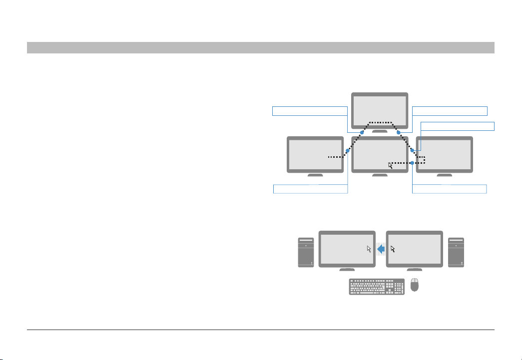
What is Seamless Cursor Switching?
Seamless Cursor Switching (SCS) is implemented in Belkin Secure KMs to
enable seamless cursor and keyboard switching between multiple displays.
SCS allows to configure any desired multiple display configuration using
the same, or different size displays and resolutions. Simply move the
mouse cursor across neighboring displays to switch between connected
computers.
Refer to the example in the figure on the right. Assume that computer #1 is
connected to the left display, computer #2 is connected to the top display,
computer #3 is connecte d to the center bottom display and computer #4 is
connected to the display on the right side. In this example all four displays
are identical. SCS allows the user to move the mouse cursor across the four
displays while automatically switching the shared peripherals (keyboard,
mouse and audio) based on the current cursor location. For example, when
the user moves the cursor from the lef t display to the center bottom display,
the KM identifies the display border crossing between these two displays
and switches the keyboard and mouse to computer #3.
SCS is now further enhanced with the inclusion of pointing device drivers
to suppor t dual, triple and up to 16 head computers. With this technology,
user workstations may be integrated with any combination of single, dual,
triple and quad head computers. SCS Configurator software enables to
easily configure any set of display sizes, resolutions, geometry and physical
arrangements.
KM switches from channel 3 to 2
1 3 4
KM switches from channel 1 to 3
PC1 PC2
2
KM switches from channel 2 to 3
KM switches from channel 3 to 4
KM switches from channel 4 to 3
Belkin® Secur e 4/8 port KM S witch User Ma nual
9
Page 12

OVERVIEW
Table of Contents
SECTIONS
1 3 4 5 6 7
2
Equipment Requirements
Cables
Belkin highly re commends you use you use Belkin Cable Kits for your
produc t to help ensure superior security and per formance. These cables
offer the highest quality possible and optimal data transmission.
One Cable Kit is required per connected computer.
Note: Due to USB signal limitations, the cable length cannot exceed 15
feet (4.6m) unless a USB extender is used.
Belkin USB w ith Audio Cables:
F1D9022b06 – 6ft (1.8m)
F1D9022b10 – 10ft (3m)
Belkin USB Cables:
F3U133-06 – 6 f t. (1.8m)
F3U133-06 – 10 ft. (3m)
Belkin Audio Cables:
F8V203tt06-E3-P– 6 ft. (1.8m)
User Operating-System (OS) Support
The Belkin Secure KM is compatible with computers running on, the
following OS platforms:
• Microsoft® Windows®
• Red Hat®, Ubuntu® and other Linux® platforms
• Mac OS® X v10.3 and higher.
User Multiple-head Operating-System (OS) Support
The Belkin Secure KM multiple-head driver is compatible with computers
running on the following OS platforms:
• Microsoft® Windows®
System set up Operating-Sy stem (OS) Support
The Belkin Secure KM setup software suite is compatible with computer s
running on the following OS platforms:
• Microsoft® Windows®
Belkin® Secur e 4/8 port KM S witch User Ma nual
10
Page 13

OVERVIEW
Table of Contents
USB Keyboard cons ole port
The product console USB keyboard port is compatible with Standard USB
keyboards.
Notes:
a. Console USB keyboard and mouse ports are switchable, i.e.
you can connect keyboard to mouse port and vice versa.
However, for optimal operation it is recommended to connect
USB keyboard to console USB keyboard port and USB mouse
to console USB mouse por t.
b. For security reasons products do not support wireless
keyboards. In any case do not connect wireless keyboard to
product.
c. Non-standard keyboards, such as keyboards with integrated
USB hubs and other USB-integrated devices, may not be
fully supported due to se curity policy. If they are supported,
only classical keyboard (HID) operation will be functional. It is
recommended to use standard USB keyboards.
SECTIONS
1 3 4 5 6 7
2
USB Mouse consol e por t
The product console USB mouse port is compatible with standard USB
mice.
Notes:
a. Console USB keyboard and mouse ports are switchable, i.e.
you can connect keyboard to mouse port and vice versa.
However, for optimal operation it is recommended to connect
USB keyboard to console USB keyboard port and USB mouse
to console USB mouse por t.
b. Console USB mouse port supports Standard K VM Extender
composite device having a keyboard/mouse functions.
c. For security reasons products do not suppor t wireless mice. In
any case do not connect wireless mouse to product.
PS/2 Mouse and Keyboard console por ts (F1DN104K-3)
The product console PS/2 keyboard and mouse por ts are compatible with
standard PS/2 keyboards and mice.
Belkin® Secur e 4/8 port KM S witch User Ma nual
11
Page 14

OVERVIEW
Table of Contents
User Audio Devices
Product is compatible with the following types of user audio devices:
• Stereo headphones;
• Amplified stereo speakers.
Note: In any case do not connect a microphone to product audio output
port including headsets.
Programming Cable
Special programming cable is needed to connect the product to the
setup PC and configure it. Cable is supplied with each product. If
needed, please contact Belkin Sales or Technical Support for additional
cable.
SECTIONS
1 3 4 5 6 7
2
Belkin® Secur e 4/8 port KM S witch User Ma nual
12
Page 15

OVERVIEW
Table of Contents
SECTIONS
F1DN104K-3 Front Panel Features
1 Port Selector 3 Name La bel Gu ide 5 Tamper-Evident Seal
2 LED Indicator 4 Color Chip
F1DN104K-3 Back Panel Features
3 4 5 6 7 8 91 2
1 DCU por t - non op erable, for fu ture us e 4 Console USB mouse port 7 Console PS/2 mouse port
2 DC power input jack 5 Console USB keyboard port 8 Co mpute r USB KM po rt
3 Console Audio Out port 6 Console PS/2 keyboard port 9 Computer audio port
1 3 4 5 6 7
2 5431
2
Belkin® Secur e 4/8 port KM S witch User Ma nual
13
Page 16

OVERVIEW
Table of Contents
SECTIONS
F1DN108K-3 Front Panel Features
2 3 541
1 LED Indicator 3 Color chip 5 Tamper Evident Label
2 Port Selector 4 Name La bel Gu ide
F1DN108K-3 Back Panel Features
32 4 7 85 61
1 DCU por t - non op erable, for fu ture us e 4 Console USB keyboard port 7 AC power switch
2 Console Audio Out port 5 USB KM po rt 8 AC power inp ut jack
3 Console USB mouse port 6 Computer audio port
1 3 4 5 6 7
2
Belkin® Secur e 4/8 port KM S witch User Ma nual
14
Page 17

OVERVIEW
Table of Contents
SECTIONS
1 3 4 5 6 7
2
Product Specifications
Part N o. F1DN104K-3 (4-por t vers ion)
Enclosure Metal enclosure with high-impact aluminum
Power Requirements (F1DN104K-3) 12V DC, 1.5A (max imum)
AC Input Voltage 100 to 240VAC
No. of Us ers S uppo rted 1
No. of Computers Supported (F1D N10 4K- 3) 4
Console Keyboard Input (F1DN104K-3) U SB Type A +
Console Mouse Input (F1DN104K-3) US B Type A +
Console Headset /
Speaker output jack
Computer Keyboard/Mouse Ports USB Type B
Computer Audio Input Jack 1/8" (3.5mm) fe male
F1DN108K-3 (8-port version)
faceplate
power adapter with center-pin-positive
polarity
(F1DN 108K-3) 100 –240VAC, 0.9 A
Freq. 50/60Hz
(F1D N10 8K- 3) 8
PS/2 Mini-DIN 6-pin female connector
(F1DN108K-3) USB Type A co nnec tor
PS/2 Mini-DIN 6-pin female connector
(F1DN108K-3) USB Type A
1/8" (3.5mm) fe male
Port Selector push-buttons (F1D N104K- 3) 4
Channel Selected LED Indicators (F1D N10 4K- 3) 4
User C hann el Se lect ion M ethods Front panel push-buttons, SCS
Settings Display physical size, display resolution X /
Operating Temp 32° to 104° F (0° to 40 ° C)
Storage Temp -4° to 140° F (-20° to 60° C)
Humidity 0-80% RH, non-condensing
MTBF 14 years (pe r MIL-HDBK-217E)
Warranty 3 years
Dimensions
Weight (F1DN104K-3) 4 lbs. / 1.81 KG
(F1D N10 8K- 3) 8
(F1D N10 8K- 3) 8
Y, display orientation (portrait /landscape),
display head (1st, 2nd,16th), display location
(coordinates), mouse speed (1-10), mouse
acceleration (1-10), SCS enable / disable,
prevent transition while dragging – enable
/ disable.
(F1DN104K-3) 12.5 (W ) x 6.4 (D) x 1.7 (H) inc h
/ 317.5 (W) X 162.5 6 (D) X 43.18 (H) mm
(F1DN108K-3) 17.25 (W) x 7.95 (D) x 1.7 (H)
inch / 438.15 (W) X 201.93 (D) X 43 .18 (H) mm
(F1DN108K-3) 9 lbs / 4.0 8KG
Belkin® Secur e 4/8 port KM S witch User Ma nual
15
Page 18

INSTALLATION
Table of Contents
SECTIONS
1 2 4 5 6 73
Before Installation
Unpacking the Product
Before opening the product packaging, inspect the packaging seal
condition to assure that product was not accessed or tampered during
deliver y. If the packaging seal looks suspicious, contact Belkin Technical
Suppor t and do not use the product.
After removing the packaging seal, please inspect packaging content to
verify that required components included as listed in the Package Contents
of this manual.
After the Belkin Secure KM is removed from its packaging materials, inspect
the four tampering-evident labels to assure that product is properly sealed.
If one or more label is damaged or missing, contact Belkin Tech Suppor t
and do not use that product.
Wher e to place the Switch:
The enclosure of the Switch is designed for desktop or under-the-desk
mount configurations. An optional Mount Kit (Belkin part number F1D006)
is available for the F1DN104K-3. Rack-mount brackets are included with
the F1DN108K-3.
Consider the following when deciding where to place the Switch:
• Access to the front-panel push buttons is not required, since the
switching can be done through the Seamless Cursor Switching (SCS)
interface.
• The lengths of the cables attached to your keyboard and mouse
• The location of your computers in relation to your console
• The lengths of the cables you use to connect your computers
to the Switch
Warning: Avoid placing cables near fluorescent lights, air-conditioning
equipment, or machines that create electrical noise (e.g., vacuum cleaners).
Important:
1. If the unit’s enclosure appears disrupted or if all channel-select LEDs
flash continuously, please remove product from service immediately
and contact Belkin Technical Support at (800) 282-2355.
2. Do not connect switch to computing devices:
a. That are TEMPEST computers;
b. That include telecommunication equipment;
c. That include frame grabber video cards;
d. That include special audio processing cards.
Belkin® Secur e 4/8 port KM S witch User Ma nual
16
Page 19

INSTALLATION
Table of Contents
SECTIONS
1 2 4 5 6 7
Connection and Installation
For security reasons products do not suppor t wireless keyboards and
mice. In any case do not conne ct wireless keyboard and mouse to
product.
Step 1 – Conne cti ng the Console Devices to the Belkin Secure K M
Warning: Before attempting to connect anything to the Switch, or your
computers, please ensure that all computer equipment and devices are
powered off.
1.1 Connect each monitor direc tly to the computers. Optionally for easier
referencing, label each computer and monitor coupled together.
1.2 Connect the user keyboard to the Console section of the Switch. For
USB-type keyboards, connect to the USB port marked “Keyboard.”
For PS/2-type keyboards, connect to the PS/2 port marked “PS2 K.”
1.3 Connect the user mouse to the Console section of the Switch. For
USB-type mice, connect to the USB port marked “Mouse.” For PS/2type mice, connect to the PS/2 por t marked “PS2 M.”
Note: The Switch will not operate properly if the keyboard and mouse are
not connected to their respective locations as listed on the steps above.
Additionally, keyboards with integrated USB hubs, card-readers, storage
devices or multimedia extensions are not supported. Only keyboard
functions are suppor ted for devices conne cted to the keyboard ports
while mouse USB console port suppor ts both keyboard and mouse.
3
Connect a user headphone or amplified speakers to the audio output por t
marked “Audio” on the Console section of the Switch.
Caution: Do not connect a microphone or headset to the audio output
port.
Step 2 – Conne cti ng Com puters to t he Belkin Secu re KM
2.1 Connect each computer to the Switch por ts marked “K /M” with
standard USB A to B cables (Belkin part number F3U133-06 or
F3U133-10). Each USB cable can be connected to any fre e USB port
in the computer.
Notes: If the quantity of computers is less than the number of K /M
ports, connect the computers sequentially (K /M port 1, K/M port 2, etc.).
The USB cable must be connected directly to a free USB port on your
computer with no USB hubs or other devices in between.
2.2 Connect each audio cable (Belkin par t number F8V203t t06 -E3-P) from
the Switch to each computer’s audio output (lime green color) or line
output (blue color) jacks.
Belkin® Secur e 4/8 port KM S witch User Ma nual
17
Page 20

INSTALLATION
Table of Contents
SECTIONS
1 2 4 5 6 7
Step 3 – Powering Up
3.1 Power on all of the monitors.
3.2 Connect the Belkin Secure KM to the cable DC plug of the 12V 1.5A
external AC/DC power supply (F1DN104K-3).
3.3 Connect the power cable IEC power plug to KM switch AC power inlet
and then the power plug to a nearby wall outlet. Turn on the power
switch located near the AC power inlet.
3.4 Power up all the attached computers, and check for display and
peripheral functionalit y. All computers can be powered on.
Notes: Your computers should recognize the Belkin Secure KM and
automatically install the HID USB driver if necessar y.
You should be able to move the mouse cursor on the primary display
connected to computer #1. Check to see that the keyboard and mouse are
working normally on each computer. Repeat this check with all occupied
ports to verif y that all computers are connected and responding correctly.
If you encounter an error, check your cable connections for that computer
and reboot. If the problem persists, please refer to the Troubleshooting
section in this User Manual.
3
Color Code Chip Installation
The Belkin Advanced Secure KM Switch’s por t-selector buttons can be colorcoded for easier identification. Refer to the installation instructions below.
Note: You may have to remove the existing black color chip fir st.
Insert color chip Remove color chip w ith
a standard paperclip
Port Name Label
The included network-name labels can be placed in the area underneath the
port-selector buttons for port identification. Blank labels are also provided.
Belkin® Secur e 4/8 port KM S witch User Ma nual
18
Page 21

INSTALLATION
Table of Contents
SECTIONS
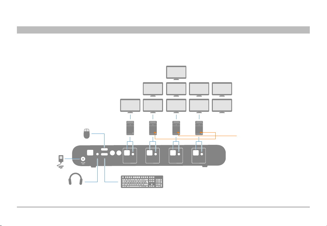
F1DN104K-3 Typical system installation
Mouse
DC
Audio
1 2 4 5 6 7
3
Displays
Computers
Mouse
DCU
Audio
Console
Keyboard
PS/2 K PS/2 M
AudioK/M
4
AudioK/M
3
AudioK/M
2
AudioK/M
1
Keyboard
Belkin® Secur e 4/8 port KM S witch User Ma nual
19
Page 22
INSTALLATION
Table of Contents
SECTIONS
1 2 4 5 6 7
F1DN104K-3 typical installation with multiple displays per connected PC
Mouse
Mouse
Keyboard
DC
DCU
Console
PS/2 K PS/2 M
Audio
AudioK/M
4
Audio
AudioK/M
3
3
2
Keyboard
Displays
Computers
AudioK/M
AudioK/M
1
Belkin Multi-Display
Mouse Driver
Required for machines
running two displays or more
Belkin® Secur e 4/8 port KM S witch User Ma nual
20
Page 23

INSTALLATION
Table of Contents
SECTIONS
1 2 4 5 6 7
Advanced Setup
Once the Belkin Secure KM is connected and powere d on, essential
operational settings needs to be configured.
The first and most important setting of the Switch is the monitor positioning.
It is essential that the Switch configuration will match the actual positioning
on the monitors.
There are two ways to configure the Switch with the actual monitor setup:
• Select one of the predefined setups
• Create a configuration file and load it to the Switch
Selecting one o f the p redefin ed setups
To load one of the default settings available in the non-volatile memory of
the Switch:
3. Select a default configuration type on the console keyboard by
pressing the following keys in this sequence: CTRL, CTRL, F11 ,
Fx (refer to the Pre -Defined Configuration List). For example: The
key sequence CTRL, CTRL, F 11, F2 will set the displays laid out
horizontally, with the left-most display to computer #1, the second
display as computer #2, the third display as computer #3, and the
fourth display to computer #4.
4. Power-cycle the Switch by disconnecting the power plug and
reconnecting to the Switch.
5. The Switch will boot with the new configuration.
Note: Additional settings can be accessed through CTRL, CTRL, x, y
(refer to the Pre-Defined Configur ation List).
3
The loaded configuration will also include the following settings by default:
• All displays are 1920 x 1200 resolution, same size (26” diagonal)
• Mouse acceleration is set to 6
• Mouse speed is set to 5
• SCS is enabled
• Prevent transition while dragging feature is Enabled
Creating a custom configuration file (Optional)
In case the required configuration does not appear on the predefined
configurations list, you can create a configuration file using Belkin’s
Secure KM Configuration Utility Tool and load it to the Switch. For more
information about this option, please refer to Appendix A and Appendix
B of this use r manual.
Notes:
1. Keyboard shortcut keys are to be pressed sequentially
2. CTRL key refers to LEFT CTRL ke y.
`~1!2@3#4$5%6^7&8*9(0)-_=
Tab
Q W E R T Y U I O P
Caps
A S D F G H J K L
Shift
Z X C V B N M
CtrlCtrl Alt Alt
+
[{]
:
“
;
‘
?/>.<
,
Delete
}
Page
Num
Insert
Home
=
/
UP
Lock
|
Page
Delete
End
Down
\
Enter
é
Shift
Ctrl
ç ê è
7 8 9
4 5 6
1 2 3
0
*
-
+
Enter
,
Belkin® Secur e 4/8 port KM S witch User Ma nual
21
Page 24
INSTALLATION
Table of Contents
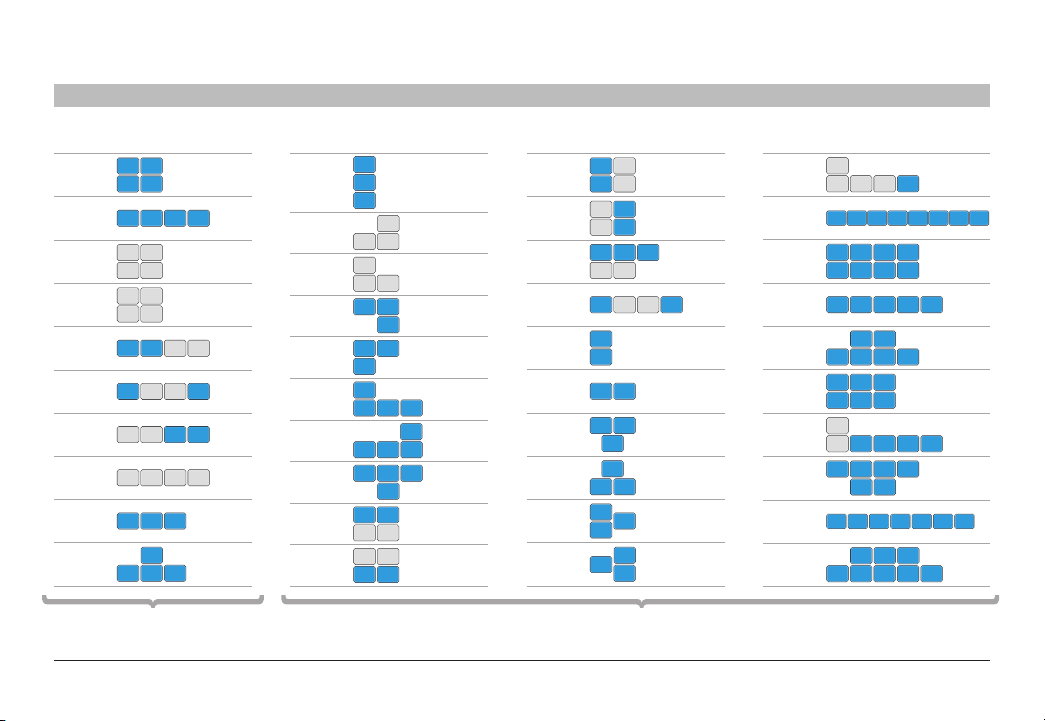
F11, F1
F11, F2
F11, F3
F11, F4
F11, F5
F11, F6
F11, F7
F11, F8
F11, F9
F11, F10
Pre- Define d Confi gurati on List -
1 2
3 4
1 2 3 4
1P 1S
3P 3S
1P 3P
1S 3S
1 2 3P 3S
1 2P 2S 4
1P 1S 3 4
1P 1S 3P 3S
1 2 3
2 3 4
Using CT RL, CT RL, F 11, Fx
(Factor y Default)
1
SECTIONS
F11, 1, 1
F11, 1, 2
F11, 1, 3
F11, 1, 4
F11, 1, 5
F11, 1, 6
F11, 1, 7
F11, 1, 8
F11, 1, 9
F11, 1, 0
1 2 4 5 6 7
1
2
3
1
2 3
1
2 3
1 2
3
1 2
3
1
2 3 4
2 3 4
2 3 4
1 2
3P 3S
3P 3S
1 2
1
1
3
F11, 2, 1
F11, 2, 2
F11, 2, 3
F11, 2, 4
F11, 2, 5
F11, 2, 6
F11, 2, 7
F11, 2, 8
F11, 2, 9
F11, 2, 0
1 3P
2 3S
3P
1
3S 2
2 3 4
1P 1S
1 2P 2S 3
1
2
1 2
1 2
3
3
1 2
2
3
1
2
3
1
Pre- Define d Confi gurati on List -
Using CT RL, CT RL, F 11, x, y
F11, 3, 1
F11, 3, 2
(8-Port Only)
F11, 3, 3
(8-Port Only)
F11, 3, 4
(8-Port Only)
F11, 3, 5
(8-Port Only)
F11, 3, 6
(8-Port Only)
F11, 3, 7
(8-Port Only)
F11, 3, 8
(8-Port Only)
F11, 3, 9
(8-Port Only)
F11, 3, 0
(8-Port Only)
1P
1S 2P 2S 3
1 2 3 4 5 6 7 8
5 6 7 8
1 2 3 4
1 2 3 4 5
5 6
5 6
6 7 8
1 2 3 4
4 5 6
1 2 3
1P
1S 2 3 4 5
1 2 3 4
1 2 3 4 5 6 7
1 2 3 4 5
Belkin® Secur e 4/8 port KM S witch User Ma nual
22
Page 25

INSTALLATION
Table of Contents
SECTIONS
1 2 4 5 6 7
Mouse Speed Set ting
Constant mouse cursor speed is essential for system usability. Having
several systems each with a different cur sor “ground speed” is detrimental
for the user. Belkin’s Secure KM calculates and adjusts the cursor speed
across different displays and computers using the geometry and display
settings preset.
In addition, the Switch settings include a global speed setting with input
values between 1 and 10, which can be changed to adjust the cursor spee d
for all displays. Typical initial setting of cur sor speed is 5. After initial use,
the exact value can be set based on user inputs.
To increase mouse spe ed, pre ss CTRL, CTRL, F11, +
To decrease mouse speed, press CTRL, CTRL, F11, -
SCS Enabled / Disabled Setting
Through the SCS enabled / disabled setting, you can disable the mouse
cursor tracking function. Once SCS is disabled – the Switch will enable
channel selection only through:
1. Front panel push-buttons;
2. Keyboard shortcuts; and:
Note: This setting is enabled by default.
3
Multiple-Head Display Driver Installation
To enable proper KM interaction with computers having multiple heads
(more than one display), the Belkin Secure KM Mouse Filter driver software
must be installed. This driver is available in an executable .E XE file that
can be installed on the target computer. Driver can be loaded from Belkin
website. If internet access is not allowed - contact Belkin to order the KM
Switch programming Kit (software CD is included in that kit.
Keyboa rd Sh ortcuts
The following table describes the keyboard shortcuts available:
Key Sequence Name Description
CTRL, CTRL,
F11, r
CTRL, CTRL,
F11, f
CTRL, CTRL,
F11, U
CTRL, CTRL,
F11, +
CTRL, CTRL,
F11, -
CTRL, CTRL,
F11, d, c
CTRL, CTRL,
F12
Reset to Fa ctory
defaults
Freeze Disab le SCS. Sw itching b etwee n system s will not
Unfreeze En able SC S. Switch ing bet ween sys tems wil l be
Increase mouse
speed
Decrease mouse
speed
Setup mode In the nex t boot af ter pre ssing th is key
Last loaded
configuration
Device w ill rese t to factor y defaults with a ll
settings and configuration deleted completely.
be poss ible via m ouse move ment.
possible via mouse movement.
Mouse sp eed wil l be incr eased.
Mouse sp eed wil l be decr eased
combin ation th e device w ill boot i nto setup m ode
allowing him to communicate with configuration
utility.
Revert to the last externally loaded configuration
(configuration loaded via configuration utility).
Belkin® Secur e 4/8 port KM S witch User Ma nual
23
Page 26

OPERATION
Table of Contents
SECTIONS
1 2 3 5 6 74
Operating the Secure KM Switch
Self-Test Procedure:
As product power s-up it performs a self-test procedure. In case of selftest failure for any reason, including jammed buttons, the product will be
Inoperable. Self-test failure will be indicated by the following abnormal LED
behavior:
• All channel-select LEDs will be turne d ON and then OFF;
• A specific, predefined LED combination will be turned ON;
• The predefined LED combination will indicate the problem type
(jammed buttons, firmware integrity).
Try to power cycle product. If problem persists please contact your system
administrator or technical support.
Now that product, computers and peripherals are connected and powered
up, it is ready for use.
Cursor Tracking (SCS Enabled)
Upon powering up, the cursor will be positioned at the center of the primary
display of computer #1. The keyboard and audio will be coupled to the same
PC where the cursor is active. Once the user moves the cursor to another
display, the keyboard and audio will follow that computer.
Front Pa nel Push Bu ttons
The default channel is #1 upon powering up. The user can select any other
channel by pressing the appropriate front panel push button. The mouse
cursor will be positioned at the center of the selec ted computer display.
If computer has multiple heads, then the cursor will be positione d at the
center of the primary display. The selected channel is indicated by LED
illuminated in the appropriate push button. The keyboard and audio will
follow the selected channel.
Prevent transition while dragging feature
The Belkin Secure KM offers a unique feature that further improves
usability – Prevent Transition while Dragging. If the user drags an object
on one display (while left mouse key pressed), the cursor would not leave
that display.
This feature prevents the loss of that dragging action while accidentally
crossing display border line.
Belkin® Secur e 4/8 port KM S witch User Ma nual
24
Page 27

OPERATION
Table of Contents
Cursor Acceleration and Speed
Cursor speed and acceleration is a combination of few factors such as
display size, resolution and static settings. If the current settings are not
constant across the different displays or not working properly, please ask
your system administrator for assistance. Both cursor acceleration and
speed can be set by the administrator to reach desired settings.
Important:
If you are aware of potential security vulnerability while installing or
operating this product, we encourage you to contact us immediately at
the following email address:gov_security@belkin.com
Thegov_security@belkin.comemail address is not intended to reach
technical support on Belkin products or services.
SECTIONS
1 2 3 5 6 7
4
Belkin® Secur e 4/8 port KM S witch User Ma nual
25
Page 28

TROUBLESHOOTING
Table of Contents
SECTIONS
1 2 3 4 6 75
General
As product powers-up all channel-select LEDs are turned ON and
then O FF. After that a specific, predefined LED com bination is turned
ON. Product is inoperable.
• The product did not pass self-test procedure. Try to power cycle
product. If problem persists please contact your system administrator
or our technical suppor t.
No power, and none of the front panel LEDs is illuminati ng.
• Check that the power supply or power cable is properly connected
to the mains socket.
• Check that DC plug is fully inserted into the switch DC jack
(F1D N10 4K-3 )
• Check that the power cable IEC plug is properly inserted into the AC
power inlet jack (F1DN108K-3).
• Check that the device is powered by using optical mouse with visible
red light. If power is not available, change the power supply.
• Check that the power switch at the back of the KM switch
(F1DN108K-3 only) is on.
Channel select LEDs are blinking with audible repeating clicking
sounds.
• This occurs af ter the configuration is set. Power cycle the unit
(disconnect and re-plug the power adapter).
• If the blinking and clicking still persist after power cycling the unit,
it is possible that the device anti-tampe ring system was triggered.
Change the unit and call Belkin technical support.
Keyboard
Mouse not working (all channels)
• Check that the mouse is not plugged into keyboard por t, and
vice-versa.
The computer does not detect my keyboard, or my keyboar d does not
work wh en I swi tch computers or reboot.
• Check that the keyboard you are using is connected properly to the
KM Switch.
• Check that the USB cable between the KM Switch and the compute r
is completely connected.
• Try connecting to a different USB port on the computer.
• Make sure the keyboard works when directly plugged into the
computer (the HID USB driver is installed on the computer). Rebooting
may be necessary when trying this.
• Make sure you are not using a keyboard with an integrated USB hub
or other USB-integrate d devices.
• If the computer is coming out of standby mode, allow up to one
minute to regain mouse function.
• Try a different keyboard.
Belkin® Secur e 4/8 port KM S witch User Ma nual
26
Page 29

TROUBLESHOOTING
Table of Contents
The CAPS, NUM , and Scroll Lock lights on my keyboard do not
function when I c onnect to t he Sw itch.
This is normal operation. The lock-state information is fully functional.
Due to the se curity of the Switch and known exploitation of lock-state
information for leakages, the LED status is not supported. Please refer to
the operating system for verification of the lock-state information for CAPS,
NUM, and Scroll Lock.
Certain keyboard functions are not working
Some non-standard keyboard functions are disabled by the switch to prevent
security risks. Contact Belkin Tech Support for latest compatibilit y list.
SECTIONS
1 2 3 4 6 7
Video
Grayed-out Windows in non-selected sources (inactive computers):
• Windows become grayed- out in inactive Windows 7/8 computers.
Note: Inactive computer s are all sources except for the currently
selected computer.
• To resolve this, right click display bottom right corner and uncheck
"Peek at desktop" feature in the window that opens.
Note: The "Peek at desktop" feature is enabled by default.
5
Mouse
Mouse cursor does not leave pr imary display to second ary display in
multiple-head computer.
Driver was not installed on that computer or not installe d properly.
Reinstall driver.
The computer does not detect my mouse, or my mouse does not work
when I switch comp uters or reboot .
• Check that the mouse you are using is connected properly to the
Switch.
• Check that the USB cable between the Switch and the computer is
completely connected.
• Try connecting to a different USB port on the computer.
• Make sure the mouse works when directly plugged into the computer
(the HID USB driver is installed on the computer). Rebooting may be
necessary when trying this.
• Make sure you are not using a wireless mouse or a mouse with an
integrated USB hub or other USB-integrated devices. These are not
suppor ted by the switch due to security policy.
• If the computer is coming out of standby mode, allow up to one
minute to regain mouse function.
• Try a different mouse.
For extending USB, use only active USB extenders (over CAT5 cable).
Belkin® Secur e 4/8 port KM S witch User Ma nual
27
Page 30

APPENDICES
Table of Contents
SECTIONS
1 2 3 4 5 76
APPENDIX A – Secure KM Configuration
Utility Software (KMC Creator)
Belkin’s Secure KM Configuration Utility (KMC Creator) is an optional
software tool that allow for users using the Switch to define their monitor
setup and create a KM configuration file. The KM configuration file
(.kmc extension) will later be loaded to the Switch that will be configured
accordingly.
NOTE: Refer to Appendix B for loading the configur ation file to th e
KM switch using the KMC Loader.
Using the KMC Creator software, one can define any number of monitors
connected to each computer with different or identical sizes and screen
resolutions. T he monitors can be deployed in any physical layout. This
software also allows removal of unneeded bridges between monitors.
Before You Begin
Please contact Belkin to or der t he KM Switc h Accessory Kit.
This kit inc ludes the CD ROM disc containing files for the
BelkinKMAdminsetup.exe (installs the KMC Creator and KMC
Loader), KMMultiDisplaySetup.exe (installs the Belkin KM Mouse
Filter for multi-head display configurations), user manual, and a USB
configurator cable.
A KM configuration file is based on the number of computers that will be
connected to the KM and the number of monitors each computer will have
connected to it.
Make sure you know the sizes and native screen resolution of all monitors
connected to all computers that will eventually be connected to that KM
switch.
NOTES:
• The KM Creator and Loader software do not need to be loaded on
each computer.
• The software is to be loaded to an external computer, so that the
connected monitors and computers are accessible for display
resolutions.
• This external computer will be used to create and input that created
file into the KM.
Belkin® Secur e 4/8 port KM S witch User Ma nual
28
Page 31

APPENDICES
Table of Contents
Step 1 – Create a new Project
Each KM configuration file is called a “KM Configuration Project”. For every
setup you will be required to create a new project. Click “Back” to return to
the previous stage, at any point during the configuration process.
• Click on “New Project”
SECTIONS
1 2 3 4 5 7
6
Step 2 – Enter Project Details
Please enter the requested information in the following manner:
• Project Name – The name can be a combination of English characters
or numbers. It is advised to use a name that will be reflective of the
configuration for example: “Dealer 3 5 monitors”, “Generic Workstation
7”. The project name can be read from the KM after loading.
• Product Model – The product model can be found on the back sticker
of the KM switch. The Belkin Secure KM can both support two to four
computers.
• Mouse Speed – This is the default mouse speed for all systems.
Change the mouse speed on each computer will not af fect the KM
mouse speed.
• Mouse Acceleration – Same as above.
• Number of Computers – The total numbers of computers that will be
connected to the KM for this configuration.
• Click “Next Step”
Belkin® Secur e 4/8 port KM S witch User Ma nual
29
Page 32

APPENDICES
Table of Contents
SECTIONS
1 2 3 4 5 7
Step 3 – Enter Description
Add the description that will explain the project. T he description will appear
in the configuration file (.kmc) and can help explain the configuration.
Step 4 – Computer Setup
In this stage, define the number and t ype of monitors connected to each
computer as defined is step 2. For ever y computer, define the number of
monitor s conne cted to the computer by selecting it from the drop down
menu “Number of Displays”. The maximum number of possible displays is
limited to four per computer.
Once the number of monitor s is selected, you will be able to enter the size
and native resolution for every monitor.
Note, if certain monitor is set to Portrait orientation, the Native resolution
should be entered accordingly. For example, for a monitor with a native
screen resolution of 1680x1050 which is used in Portrait please enter
resolution of 1050x1680.
Number of Monitors
Display SIze Native Resolution
6
Multiple-heads setup
When creating a setup with multiple -heads for one of the computers,
there is an additional requirement to enter the Microsoft virtual desk top
parameters.
Note: Newer versions of the KMC creator application does not re quire
the MS W/H Coordinates.
When using multiple monitors on one of the machines, both the KM and MS
Extended desktop are controlling the switching between the displays. Both
mechanisms need to work synchronously.
Belkin® Secur e 4/8 port KM S witch User Ma nual
30
Page 33
APPENDICES
Table of Contents
SECTIONS
1 2 3 4 5 7
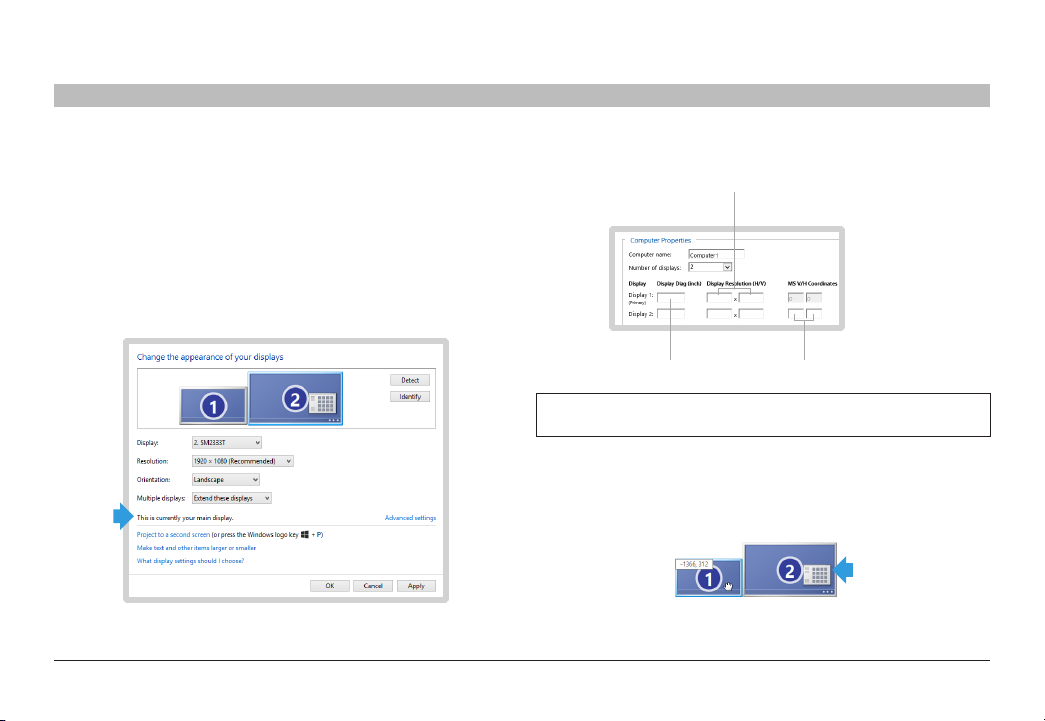
The following instructions and screen captures are based on Windows 7,
but can be used for Windows XP and Windows Vista.
• Go to: “Control Panel\All Control Panel Items\Display\Screen
Resolution”. You can also right- click your desktop and select screen
resolution.
• In the KM configuration dialog you will be asked to provide information
regarding your primar y display. Primar y display is defined as “main
display” in the MS “Screen Resolution” dialog. You can see which is
defined as your main display by selecting it in the MS dialog.
6
• Enter the details for you main display as reque sted in the dialog.
Monitor Native
Resolution
Monitor SIze
MS Coordinates
Note: Newer versions of the KMC creator application does not re quire
the MS W/H Coordinates.
Enter the details for the secondary display. To find out what are the ver tical
and horizontal MS values, select the secondar y monitor and move it slightly.
Two numbers will appear on the secondary monitor. Enter both numbers in
the dialog.
Belkin® Secur e 4/8 port KM S witch User Ma nual
31
Page 34

APPENDICES
Table of Contents
Step 5 – Place the Displays and Create the Geom etr y
In this stage create displays setup. Drag and drop the monitors that were
created in proportion which reflects the size and shape of his actual
monitor s until he create a view similar to his real environment.
Each display is clearly marked by his compute r number and monitor
number as entered in the previous stage.
Monitor s can be connected or have some distance all based on the actual
geometry required.
Once the monitor s are placed Yellow “bridges” will indicate area in which
the mouse “teleport” itself from one monitor to another.
Clicking on one of these areas will remove it which will prevent the mouse
cursor from “teleporting” through this bridge.
To enable the bridge between monitor s, just drag one monitor to the desired
monitor, having them touch each other. Pull apart the monitors, and the
bridge should appear between the monitors again.
SECTIONS
1 2 3 4 5 7
6
Examples:
Example 1 – The following setup creates a corridor from the top right of
monitor 2 computer 2 to the top bottom left of monitor 1 computer 1.
Trying to drag the mouse through the red lines will not work.
Example 2 – Both configurations below create identical setups in which the
mouse cursor moves from the right of computer 2 to the lef t of computer 1.
Belkin® Secur e 4/8 port KM S witch User Ma nual
32
Page 35

APPENDICES
Table of Contents
Example 3 – The setup shown below is invalid. There is no interface
between the two monitor hence the curser will not move. It is recommended
to use the below bottom setup instead which will give similar results.
SECTIONS
1 2 3 4 5 7
6
Belkin® Secur e 4/8 port KM S witch User Ma nual
33
Page 36
APPENDICES
Table of Contents
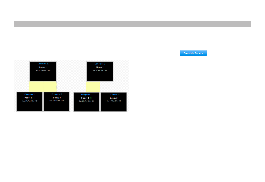
Example 4 – The two setups below are identical except that on the right
setup, the user chose to prevent the mouse cursor from moving from:
Computer 2, Display2 to Computer 1, Display 1.
This was done by clicking on the Yellow area between the monitors.
Multi Displays Rules
• Computers with multi displays Rule #1 – When one of the computer s is
configured with multi displays, the setup of those displays connected
to the same PC must be similar to that configured on the MS setup.
• Computers with multi displays Rule #2 – All displays connected to
the same PC must be stuck to one another. It is impossible to have
distance between two displays connected to the same PC.
SECTIONS
1 2 3 4 5 7
6
Step 6 – Complete Setup
Once ready the press the Complete Setup bottom.
A file with an extension ending in “.kmc” will be generated.
Please refer to Appendix B for instructions on how to upload the .k mc
configuration file to the target KM Switch/Switches.
Belkin® Secur e 4/8 port KM S witch User Ma nual
34
Page 37
APPENDICES
Table of Contents
SECTIONS
1 2 3 4 5 7
APPENDIX B – Secure KM Configuration
Utility (KMC Loader) Software
Belkin’s Secure KM Configuration Utility (KMC Loader) allows you to load
the configured .kmc file (created per the procedure defined in Appendix A
of this manual) into the Secure KM Switch.
NOTE: Pl ease refer to App endix A for instructions on instal ling the
BelkinKMAdminsetup.exe file (that installs the KMC Creator and
KMC Loa der progr ams) and cr eate the .k mc files ne eded for the
following steps.
Setting u p the K M Switch for Loading the Configu rat ion (.kmc) File
The KM switch is configured through a cable connected from a PC
containing the KMC Loader to the KM USB mouse port. The connection
is done via a special USB programming cable that is supplied with each
product.
1. Disconnect the mouse from to the Console mouse port of the KM
switch.
2. Connect the USB programming cable from a PC USB por t to the
console USB mouse por t of the target KM Switch.
3. Put the KM switch in setup mode by typing on the connected keyboard
(CTRL , CTRL , F11, d, c). The KM Switch will click several times to
audibly indicate that it needs to be power-cycle d.
6
Loading Utility
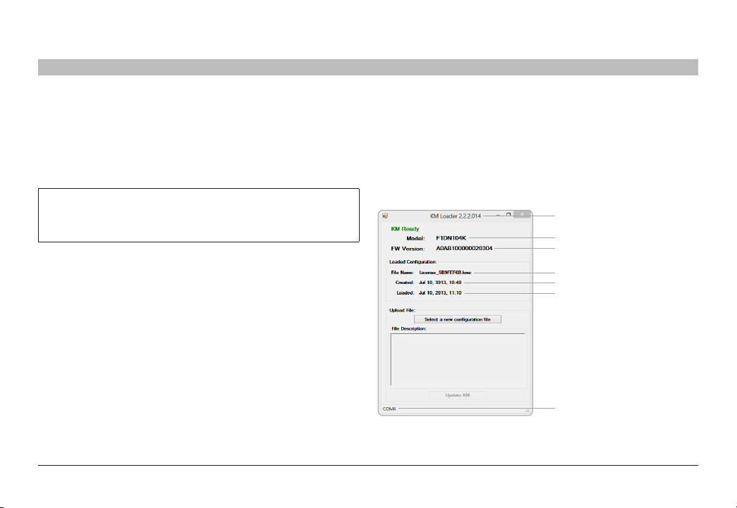
Once the KM Switch is in setup mode and is connected to the PC:
4. Run the loading utility (KMC Loader). Wait for five to ten seconds until
the KMC Loader window shows “KM Ready”, as shown:
Version Number
Model Name
FW Version
Previously Loaded file name
Previously Loaded file Create Date
Previous Load Date
Communication Port
Figure 1 – K M Loading Utility c aptur e – before sel ectin g a file
Belkin® Secur e 4/8 port KM S witch User Ma nual
35
Page 38
APPENDICES
Table of Contents
SECTIONS
1 2 3 4 5 7
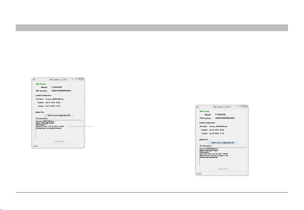
Loading a Configuration file
• Click on the “Select a new configuration file”
• Browse to your .kmc configuration file
• Click on “Update KM”
After the .kmc file is loaded, the following screen will show:
Loaded File Parameters
Figure 2 – K M Loading Utility c aptur e – file s elec ted and l oade d
After loading is complete, restart the KM by disconnecting and then
reconnecting power. Reconnect the mouse back to the mouse port and the
new configuration will apply.
6
KM Load er Troub leshooting and Suppor t
The KMC Loader utility communicates with the KM switch to load the
configuration file.
The two most common errors when using the loading utility are:
• Configuration file incorrectly formatted
• No Communication with KM switch
When loading a wrong configuration file the Loading Utilit y will report the
issue if possible and will direct the user to load another file.
To avoid this make sure the files you have loaded were created with the KMC
Creator configuration tool and that it was not manually modified in any way.
Figure 3 – K M Loading Utility c aptur e – File no t corr ect
Belkin® Secur e 4/8 port KM S witch User Ma nual
36
Page 39

APPENDICES
Table of Contents
The loading utility communicates with the KM switch once the KM switch
has entered setup mode. Once the KM is conne cted, with the loading utility
correctly the utility GUI will s ay “KM Ready” and the connected port will
also appear as seen in figure 1 of Appendix B.
If the utility cannot communicate with KM switch, it will prompt “KM Not
Ready” and no communication port will appear.
Figure 4 – C ommu nication betwee n KM and ut ilit y has be en lost
SECTIONS
1 2 3 4 5 7
6
To avoid this, ensure that the KM switch is conne cted via the mouse (not
keyboard) Console por t on the KM Switch.
Put the KM switch in mode as explained previously.
Belkin® Secur e 4/8 port KM S witch User Ma nual
37
Page 40

INFORMATION
Table of Contents
SECTIONS
1 2 3 4 5 6 7
FCC Statement
DECLARATION OF CONFORMITY WITH FCC RULES FOR
ELECTROMAGNETIC COMPATIBILITY
We, Belkin International, Inc., of 12045 E. Waterfront Drive, Playa Vista,
CA 90094, declare under our sole responsibility that the products comply
with Par t 15 of the FCC Rules. Operation is subject to the following two
conditions: (1) this device may not cause harmful interference, and (2) this
device must accept any interference received, including interference that
may cause undesired operation.
CE Declaration of Conformity
We, Belkin International, Inc., declare under our sole responsibility that the
products, to which this declaration relates, are in conformity with Emissions
Standard EN55022 and with Immunity Standard EN55024, LVP EN610003-2, and EN61000-3-3.
ICES
This Class B digital apparatus complies with Canadian ICES-003. Cet
appareil numérique de la classe B est conforme á la norme NMB- 003
du Canada.
Belkin International, Inc., Limited 3-Year Product Warranty
What t his wa rra nty covers.
Belkin International, Inc. (“Belkin”) warrants to the original purchaser of this
Belkin product that the product shall be free of defects in design, assembly,
material, or workmanship.
What t he period of cover age is.
Belkin warrants the Belkin product for three years.
What will we do to correct problems?
Product Warranty.
Belkin will repair or replace, at its option, any defective product free of
charge (except for shipping charges for the product). Belkin reserves the
right to discontinue any of its products without notice, and disclaims any
limited warranty to repair or replace any such discontinued products. In the
event that Belkin is unable to repair or replace the product (for example,
because it has been discontinued), Belkin will offer either a refund or a
credit toward the purchase of another product from Belkin.com in an
amount equal to the purchase price of the product as evidenced on the
original purchase receipt as discounted by its natural use.
Belkin® Secur e 4/8 port KM S witch User Ma nual
38
Page 41

INFORMATION
Table of Contents
What is not covered by this warrant y?
All above warranties are null and void if the Belkin product is not provided
to Belkin for inspection upon Belkin’s request at the sole expense of
the purchaser, or if Belkin determine s that the Belkin product has been
improperly installed, altered in any way, or tampered with. The Belkin
Product Warranty does not protect against acts of God such as flood,
lightning, ear thquake, war, vandalism, thef t, normal-use wear and tear,
erosion, depletion, obsolescence, abuse, damage due to low voltage
disturbances (i.e. brownouts or sags), non-authorized program, or system
equipment modification or alteration.
How to get service.
To get service for your Belkin product you must take the following steps:
1. Contact Belkin International, Inc., at 12045 E. Waterfront Drive, Playa
Vista, CA 90094, Attn: Customer Service, or call (800)-282-2355,
within 15 days of the Occurrence. Be prepared to provide the following
informatio n:
a. The par t number of the Belkin product.
b. Where you purchased the product.
c. When you purchased the product.
d. Copy of original receipt.
2. Your Belkin Customer Service Representative will then instruct you on
how to forward your receipt and Belkin product and how to proceed
with your claim.
SECTIONS
1 2 3 4 5 6
7
Belkin reser ves the right to review the damaged Belkin product. All costs
of shipping the Belkin product to Belkin for inspection shall be borne solely
by the purchaser.
If Belkin determines, in its sole discretion, that it is impractical to ship the
damage d equipment to Belkin, Belkin may designate, in its sole discretion,
an equipment repair facility to inspect and estimate the cost to repair such
equipment. The cost, if any, of shipping the equipment to and from such
repair facilit y and of such estimate shall be borne solely by the purchaser.
Damage d equipment must remain available for inspection until the claim
is finalized. Whenever claims are settled, Belkin reserves the right to be
subrogated under any existing insurance policies the purchaser may have.
Belkin® Secur e 4/8 port KM S witch User Ma nual
39
Page 42

INFORMATION
Table of Contents
How state law r elates to the war ranty.
THIS WARRANTY CONTAINS THE SOLE WARRANTY OF BELKIN. THERE
ARE NO OTHER WARRANTIES, E XPRESSED OR, EXCEPT AS REQUIRED
BY LAW, IMPLIED, INCLUDING THE IMPLIED WARRANTY OR CONDITION
OF QUALIT Y, MERCHANTABILITY OR FITNESS FOR A PARTICULAR
PURPOSE, AND SUCH IMPLIED WARRANTIES, IF ANY, ARE LIMITED IN
DURATION TO THE TERM OF THIS WARR ANT Y.
Some states do not allow limitations on how long an implied warranty lasts,
so the above limitations may not apply to you.
IN NO EVENT SHALL BELKIN BE LIABLE FOR INCIDENTAL, SPECIAL,
DIRECT, INDIRECT, CONSEQUENTIAL OR MULTIPLE DAMAGES SUCH
AS, BUT NOT LIMITED TO, LOST BUSINESS OR PROFITS ARISING OUT
OF THE SALE OR USE OF ANY BELKIN PRODUCT, EVEN IF ADVISED OF
THE POSSIBILITY OF SUCH DAMAGES.
This warranty gives you specific legal rights, and you may also have other
rights, which may vary from state to state. Some states do not allow the
exclusion or limitation of incidental, consequential, or other damages, so
the above limitations may not apply to you.
GS 5/15/2013
SECTIONS
1 2 3 4 5 6
7
Belkin® Secur e 4/8 port KM S witch User Ma nual
40
Page 43

INFORMATION
Table of Contents
SECTIONS
1 2 3 4 5 6
Reporting Belkin Product Security Vulnerability
If you are aware of potential securit y vulnerability with any Belkin
Government product, we encourage you to contact us immediately at
the following email address: gov_security@belkin.com or our technical
suppor t line at: 1-800-282-2355.
After your communication is received, Belkin Government personnel will
contac t you to follow up. To ensure confidentiality, Belkin encourages you
to use ourPGP encr yption key.
Thegov_security@belkin.comemail address is not intended to reach
technical support on Belkin Government products or services.
7
Belkin® Secur e 4/8 port KM S witch User Ma nual
41
Page 44

belkinbusiness.com
© 2015 Belkin In ternational , Inc. All r ights r eser ved. Al l trade n ames are regis tered t radem arks of r espective ma nufac turer s liste d.
Windows and Windows Vis ta are ei ther re giste red tra demarks or tradema rks of Mic rosof t Cor porat ion in the U nited S tates and/or
other co untri es. Mac O S is a trad emark of Appl e Inc., reg istered in the U.S . and other coun tries .
 Loading...