

Page 1
OmniView
IP*
5000HQ
User Manual
8820-00058 F1DP101C
*OmniV iew is a registere d trademark of Be lkin Inte rnatio nal, Inc.
Page 2

TABLE OF CONTENTS
Table of Con tents
1 Introduction . . . . . . . . . . . . . . . . . . . . . . . . . . . . . . . . . . . . . . . . . . . .1
1.1 Key features ............................................1
1.2 System components .....................................2
1.3 Terminology ............................................2
1.4 System diagram.........................................2
2 Pre-Installation Guidelines................................3
2.1 Access Se rvices details ..................................4
2.1.1 Adding user-defined Access Services ......................4
3 Underst anding the System – An Overview ..................5
3.1 Creating users ..........................................5
3.2 Forming users into groups ................................6
3.3 Creating targets.........................................6
3.4 Forming targets into sets .................................7
3.5 Associating a user group with a target set ...................7
3.6 Access Services ........................................8
4 Set ting Up the System ..................................10
4.1 Connecting the OmniView IP 500 0HQ Manager ..............11
4.2 OmniView IP 5000HQ Manager’s default IP addres s ..........11
4.2.1 Changing the OmniView IP 5000HQ Manager
network parameters........................................11
5 Displaying the OmniView IP 5 000HQ Web Interface .........12
5.1 Menu section ..........................................13
6 Creating Users . . . . . . . . . . . . . . . . . . . . . . . . . . . . . . . . . . . . . . . . .14
6.1 General tab ...........................................15
6.2 User Group tab ........................................16
6.2.1 Removing users from a group ...........................16
SECTIONS
1 3 5 7 9 11 13 15 17 192 4 6 8 10 12
14
6.3 Access Permissions tab .................................17
6.4 Saving a use r..........................................18
6.4.1 Deleting a user .......................................18
6.5 Creating a user group ...................................19
6.5.1 Access Permissions tab................................20
6.5.2 Allowed Services tab ..................................20
6.5.3 Saving the new group .................................21
6.5.4 Deleting a user group..................................21
7 Configuring Targets .....................................22
7.1 Access Services tab ....................................23
7.1.1 Default Access Service .................................23
7.1.2 Belkin OmniView K VM Switch ...........................24
7.2 PDU tab ..............................................26
7.3 Target Sets tab ........................................28
7.4 Access Permissions tab .................................28
7.5 Saving the target .......................................29
7.6 Deleting targets ........................................29
7.7 Creating a target set ....................................29
7.7.1 Access Permissions tab ................................30
7.7.2 Saving the target set...................................30
7.7.3 Deleting a target set ...................................31
8 Management ...........................................32
8.1 Devices...............................................32
8.2 Other Devices .........................................33
8.2.1 Other Devices – PDU ..................................33
8.2.2 O ther Devices – Console Ser ver .........................35
8.3 Set ting each OmniView K VM-over-IP Switch to be OmniView IP
5000HQ-enabled ..........................................36
8.4 Configuring the K VM IP devices in the OmniView IP 5000HQ ...37
8.4.1 The Advanced button ..................................37
16
18
20 21
Omni View IP 500 0 HQ
i
Page 3

TABLE OF CONTENTS
Table of Con tents
8.4.2 Performance .........................................38
8.4.3 Mouse ..............................................38
8.5 KVM Ports tab .........................................39
8.6 Targets ...............................................40
8.7 Network Tab ..........................................40
8.8 Saving the K VM-over-IP device configuration changes ........41
8.9 Deleting K VM-over-IP devices . . . . . . . . . . . . . . . . . . . . . . . . . . . .41
8.10 Device discovery . . . . . . . . . . . . . . . . . . . . . . . . . . . . . . . . . . . . . . 41
9 Set tings – Applications ..................................42
9.1 Access Services .......................................42
9.1.1 Belkin OmniView IP KVM ...............................43
9.2 Account policy.........................................44
9.2.1 Password policy ......................................45
9.2.2 External authentication (LDAP) ..........................46
9.3 Global settings ........................................49
9.3.1 OmniView IP 500 0HQ session idle time-out................50
10 Set tings – At tach ed Devices ............................51
10.1 PDU ................................................51
10.1.1 Uploading a new PDU model ...........................51
10.2 KVM switche s ........................................52
10.2.1 Uploading a new KVM switch ..........................53
10.3 Console ser ver .......................................53
10.3.1 Uploading a new serial console model ...................54
11 Configuring Access Servi ces – Introduction ...............55
11.1 Access Services default values...........................55
11.1.1 General note about application paths ....................55
11.1.2 Belkin Serial Console Server ...........................56
11.1.3 Web ...............................................57
11.1.4 ILO ................................................57
SECTIONS
1 3 5 7 9 11 13 15 17 192 4 6 8 10 12
14
11.1.5 RD P ...............................................59
11.1.6 SSH ...............................................60
11.1.7 V NC ...............................................61
11.1.8 Telnet ..............................................63
11.1.9 VMware Server ......................................64
11.1.10 New Access Ser vices ................................65
12 Configuring Access Services for Individual Targets ........67
12.1 Default Access Service .................................67
12.1.1 Single Port Console Server ............................68
12.1.2 Web . . . . . . . . . . . . . . . . . . . . . . . . . . . . . . . . . . . . . . . . . . . . . . .69
12 .1.3 I LO ................................................69
12 .1.4 RD P ...............................................71
12 .1.5 S SH ...............................................72
12 .1.6 VN C . . . . . . . . . . . . . . . . . . . . . . . . . . . . . . . . . . . . . . . . . . . . . . .73
12.1.7 Telnet ..............................................75
12.1.8 VMware Server ......................................76
13 Accessing Targets – Adminis trator.......................77
13.1 Access page columns ..................................77
13.1.1 Power management column............................77
13.1.2 Name column .......................................77
13.1.3 Status column .......................................78
13.1.4 More Access Services column..........................78
13.2 Accessing a target via K VM-over-IP remote session .........78
13.2.1 Taking over a busy remote session ......................79
13.2.2 The toolbar .........................................79
13.2.3 Switching to a different server..........................79
13.3 Acces sing a target through other Access Services ..........79
13.4 Exiting the OmniView IP 500 0HQ system ..................80
16
18
20 21
Omni View IP 500 0 HQ
ii
Page 4

TABLE OF CONTENTS
Table of Con tents
14 Acces sing the S yste m as a User .........................81
14.1 Power column ........................................81
14.2 Status column ........................................80
14.3 Connecting to a target .................................82
14.3.1 Connecting to a KVM-over-IP device target ...............82
14.3.2 Connecting to a non-KVM -over-IP device target ...........82
14.3.3 Changing the password ...............................83
15 Accessing an K VM over IP Device Directly ................84
16 Maintena nce of the System .............................85
16.1 Backup & Restore .....................................85
16.1.1 The backup elements . . . . . . . . . . . . . . . . . . . . . . . . . . . . . . . . .86
16.1.2 Restoring database backup ............................86
16.2 Restore Set tings ......................................87
16.2.1 Restoring OmniView IP 50 00HQ to factory default settings . .87
16.2.2 Resetting OmniView IP 5000HQ configuration.............87
16.3 Firmware upgrade .....................................88
16.3.1 Upgrading the the KVM-over-IP device firmware ...........88
16.4 Replication ...........................................89
16.4.1 Connecting the secondar y unit to the network.............89
16.4.2 Configuring the se condary unit .........................89
16.4.3 Configuring the primary unit ...........................90
16.4.4 Promoting a secondary unit to a standalone unit...........90
16.4.5 Reconfiguring the primar y and secondary units ...........90
16.4.6 Primary unit and secondary unit troubleshooting ..........92
16.4.7 Checking the secondary unit...........................92
16.4.8 Redoing the secondary and primary unit configuration......92
16.5 Event log ............................................93
16.5.1 Drop-down search menus .............................94
16.5.2 Access, System, or Configuration tabs ..................94
16.5.3 Advanced button ....................................94
SECTIONS
1 3 5 7 9 11 13 15 17 192 4 6 8 10 12
14
17 Unit Maintenance ......................................95
17.1 Date & T ime tab .......................................95
17.2 Network tab . . . . . . . . . . . . . . . . . . . . . . . . . . . . . . . . . . . . . . . . . .95
17.3 Power Control tab .....................................96
18 About ................................................97
19 General Troubleshoot ing ...............................98
20 Technical Specific atio ns ..............................100
20.1 WEEE compliance ....................................101
21 Information ..........................................102
16
18
20 21
Omni View IP 500 0 HQ
iii
Page 5

INTRODUCTION
Table of Con tents
SECTIONS
1
3 5 7 9 11 13 15 17 192 4 6 8 10 12
14
16
18
About this User Manual
This User Manual provides installation and operation instructions for the OmniView IP 500 0 HQ system produced by Belkin International, Inc.
It is intended for system administrators and network managers, and assumes that readers have general understanding of networks, LDAP,
hardware, and software.
All information in this User Manual is subject to change without prior notice.
OmniView IP 50 00HQ is a robust central management appliance that
provides reliable and secure management of IP devices.
OmniView IP 50 00HQ integrates with Belkin IP devices and serial
console server devices to facilitate an intuitively manageable,
centralized out-of-band access por tal—designed to maintain all IT
assets. OmniView IP 5000HQ centralizes all user account information
relevant for IP device administration without interfering in the standalone
survivabilit y of each device.
OmniView IP 50 00HQ is Web-based, and is managed using XML over
HTTPS, which allows for secure, yet highly adaptable, administration.
Designed to work across LAN or WAN, OmniView IP 5000HQ monitors
and auto-configures KVM IP devices, whether residing on the local
enterprise network or in re mote branches.
OmniView IP 50 00HQ delivers the most advanced solution for enterprise
IT management and remote control. It supports multiple servers in
different locations in an environment that is completely configurable by
the net work administrator.
1.1 Key features
IT Managem ent - OmniView IP 50 00HQ centralizes the management
of all devices, authentication, and global operation from a web browser.
The local administrator can monitor, control, and manage the various
devices, user accounts, and authorization from one web interface.
Autom atic Discovery - Belkin IP devices are discovered automatically
by the OmniView IP 5000HQ Manager.
Acces s Ser vices - Connect to a variety of both hardware and software
external resources such as: ILO, RDP, SSH, VNC, and web pages, etc.,
from the OmniView IP 5000HQ inter face.
Security - OmniView IP 5000HQ provides an extra security layer in
addition to the existing authentication and encryption policy—ensuring
that only authorized users can access server s.
Availability - Maximizes uptime by centralizing management and
allowing immediate and effec tive maintenance.
20 21
Omni View IP 500 0 HQ
1
Page 6
INTRODUCTION
Table of Con tents
Table of Con tents
SECTIONS
SECTIONS
3 5 7 9 11 13 15 17 192 4 6 8 10 12
1
3 5 7 9 11 13 15 17 192 4 6 8 10 12
14
14
16
16
18
18
20 21
20 21
1.2 System components
The OmniView IP 5000HQ system comes with the following:
• OmniView IP 50 00HQ Manager appliance
• IEC 10A–125V Power Cord
• Rack-Mounting Kit
1.3 Terminology
Below are some terms and their meanings used in this manual.
Term Meaning
Compute rs/ser vers and other devices, e.g.,
Targets
printers, firewalls, PDUs, etc., that are accessed
remotely via the OmniView IP 5000HQ
Client
computer
The PC running a remote OmniView IP 5000HQ
session
The process of accessing and controlling
Remote session
targets connected to a KVM-over-IP device from
a client computer
Omni View IP 500 0 HQ
Omni View IP
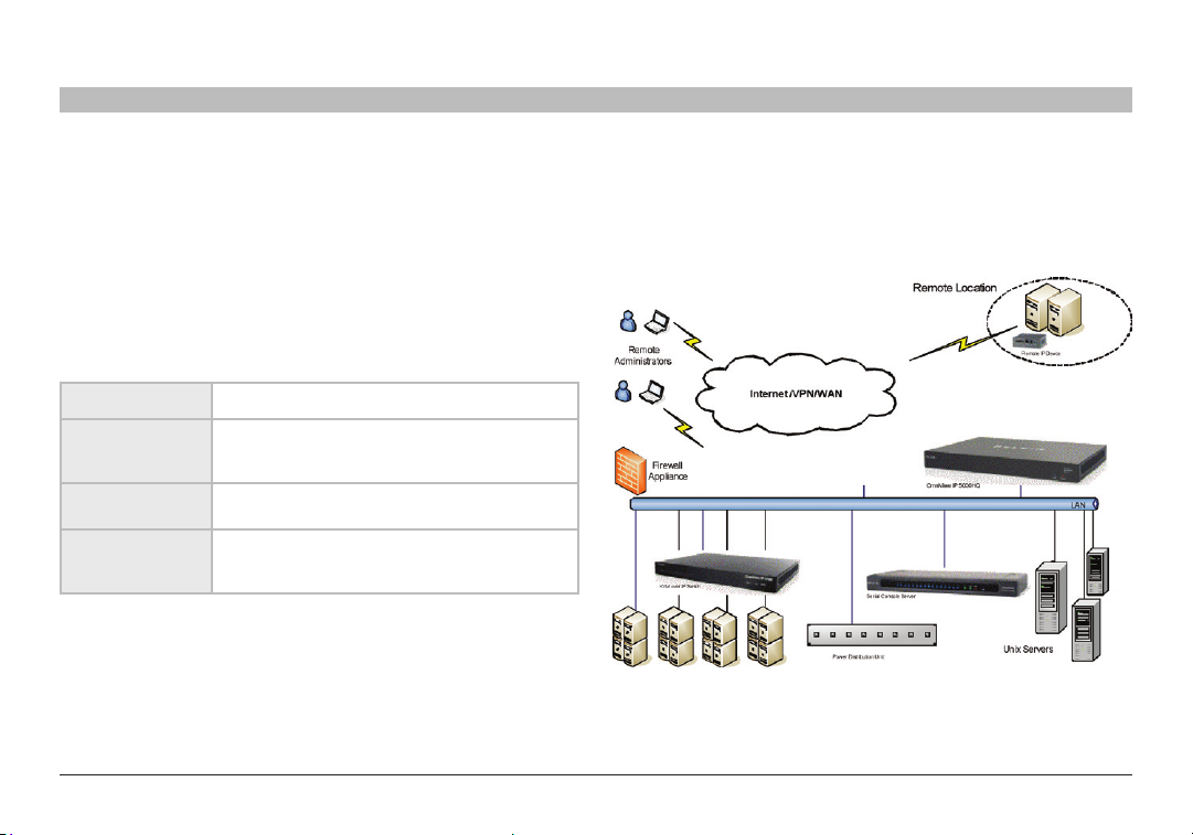
1.4 System diagram
The diagram below gives a brief outline of the OmniView IP 5000HQ
system setup. The “Unde rstanding the System” section on page 5
explains the system setup in more detail.
Figure 1
System diagram
2
Page 7
PRE-INSTALLATION GUIDELINES
Table of Con tents
SECTIONS
1 3 5 7 9 11 13 15 17 192 4 6 8 10 12
3
Prepare a list of all OmniView IP 5000HQ system components. You will
need this information to configure the system.
Appendix A (a separate file on this CD) contains three lists of the details
you need to prepare for Belkin OmniView K VM-over-IP devices, power
distribution units (PDUs), and Serial Console Servers. Photocopy or print
out Appendix A. For other Access Services, see the “Access Services
details” section on the next page.
The lists should include the IP device name and MAC address, KVM
switch, and the target details.
For each target, list:
• A unique and clearly identifiable name
• The operating system
• Non-default mouse settings. Default mouse settings do not ne ed to
be listed.
16
18
20 21
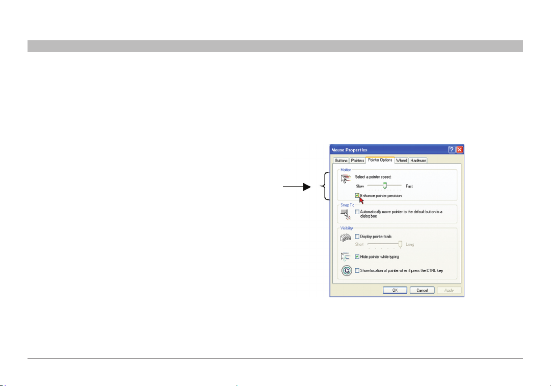
Note! For Windows
14
®
XP, 2003 Server, Vista®, and 20 08 Ser ver
For Windows XP, 2003 Server, Vista, and 2008 Server, deactivate
“Enhanced pointer precision”. To do so:
From the “Control Panel” select “Printers and Other Hardware”. Click
the “Mouse” icon. The “Mouse Proper ties” box appears. See Figure 2.
Select the “Pointer Options” tab.
Figure 2 Pointer tab
The “Motion” section slider bar must be in the center, and the
“Enhanced pointer precision” check box must be unchecked.
Click “OK” to save changes.
Omni View IP 500 0 HQ
3
Page 8

PRE-INSTALLATION GUIDELINES
Table of Con tents
2.1 Access Services details
Besides the Belkin OmniView KVM-over-IP devices mentioned above,
you can connect to targets via the following Access Ser vices through
OmniView IP 50 00HQ:
• Belkin Serial Console Ser ver
• Web
• ILO
• RDP
• SSH
• VNC
• Tel net
• VMware Server
These services are elaborated on in the “Access Services” section.
All service applications must be installed on the local (client) computers.
See the “Configuring Access Services” section on page 55, which sets
out the details required for each of the above Access Services.
SECTIONS
1 3 5 7 9 11 13 15 17 192 4 6 8 10 12
3
14
2.1.1 Adding user-defined Access Services
You can also add your own Access Services, explained on page 65.
16
18
20 21
Omni View IP 500 0 HQ
4
Page 9
UNDERSTANDING THE SYSTEM – AN OVERVIEW
Table of Con tents
SECTIONS
1 3 5 7 9 11 13 15 17 192 4 6 8 10 12
5
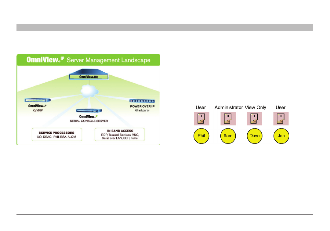
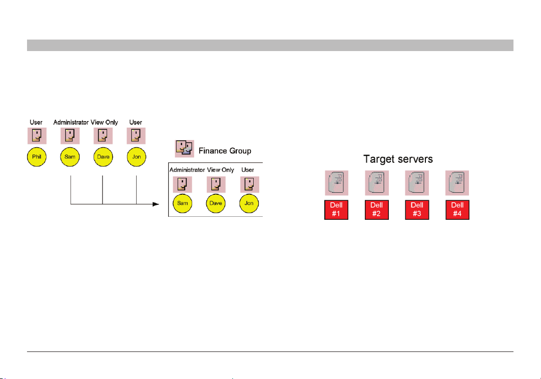
The figure below shows a typical OmniView IP 5000HQ application. 3.1 Creating users
An administrator can create users with two different possible permission
types:
• Administrator
• User
A user can be a full user or just view only. These permission types are
explained fully in the “Account policy” section. In the example below,
four users are created with various permission types.
Figure 3 OmniView IP 50 00HQ typica l application
The system works as follows:
Data centers in locations throughout the world are connected to Belkin
IP devices and to other third-part y Access Services. The Belkin IP
Once an administrator creates targets or sets of targets (explained
below) in the system, users can be assigned access to individual targets
or sets of targets.
devices are HQ-enabled, allowing the OmniView IP 5000HQ to access/
control the targets connected to all IP devices via IP.
Users access the OmniView IP 500 0HQ web inter face and, depending
on their level of access permissions, can access and control the targets.
14
Figure 4 Users with di fferent permissions
16
18
20 21
Omni View IP 500 0 HQ
5
Page 10
UNDERSTANDING THE SYSTEM – AN OVERVIEW
Table of Con tents
SECTIONS
1 3 5 7 9 11 13 15 17 192 4 6 8 10 12
5
3.2 Forming users into groups
You can form user s into groups. In the example below, three users are
formed into the Finance group. Note! Groups can contain users with
different levels of user permissions.
Figure 5 Forming user s into gro ups
14
16
18
20 21
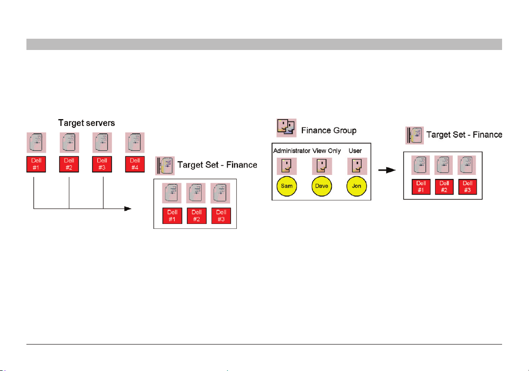
3.3 Creating targets
An administrator creates targets corresponding to the physical servers
connected to the IP devices, explained in the “Configuring Targets”
section, and also to targets corresponding to printers, firewalls, PDUs,
etc., accessed via Access Services (see page 8). In the example below,
four ta rgets are created and given identif ying names. They can be
named by location, server t ype, or operating system, or any other unique
feature associated with that particular server.
Figure 6 Created targe ts
Omni View IP 500 0 HQ
6
Page 11
UNDERSTANDING THE SYSTEM – AN OVERVIEW
Table of Con tents
SECTIONS
1 3 5 7 9 11 13 15 17 192 4 6 8 10 12
5
3.4 Forming targets into sets
Targets can be formed into sets. For example, you can create a set of
all financial servers. In the example below, three targets are formed into
target set – Finance.
Figure 7 Forming targe ts into sets
14
16
18
20 21
3.5 Associating a user group with a target set
You can then associate the user group with the target set, thus giving
access rights to all the targets in the set to all members of the group.
Figure 8 User group - t arget se t association
In the example above, the Finance group is associated with the target
set – Finance.
This means that:
• The Finance group has access rights to target set – Finance.
• Any user added to the Finance group will automatically have
access rights to target set – Finance.
Omni View IP 500 0 HQ
7
Page 12
UNDERSTANDING THE SYSTEM – AN OVERVIEW
Table of Con tents
SECTIONS
1 3 5 7 9 11 13 15 17 192 4 6 8 10 12
5
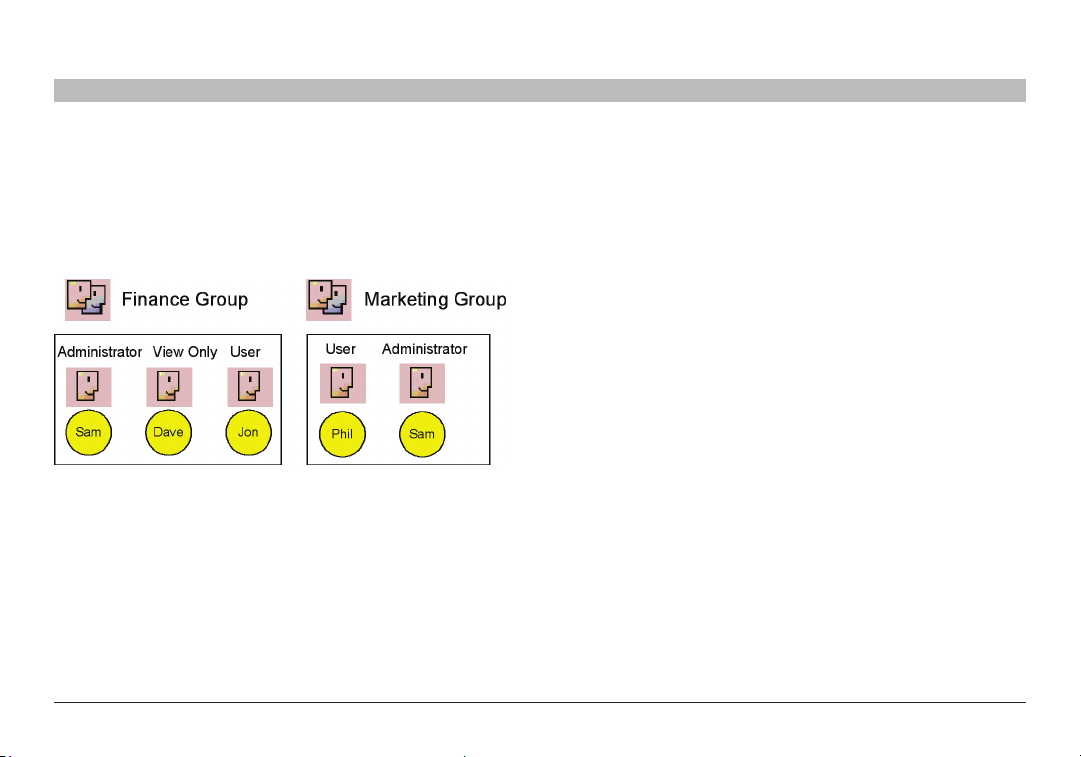
Note! Although users are members of the same group, they can have
different access permissions to targets. For example, some could be
users allowing them to control the targets, and some could be view
only, letting them see the ser ver screens, but without being able to
take control. Also, users can be members of many different groups. In
the example below, Sam belongs to the Finance group and also to the
Marketing group.
Figure 9 Same user in d ifferent gro ups
The Marketing group could be associated with targets or target sets that
the Finance group is not. Sam, being a member of both groups,
has access to targets to which both groups are as sociated. Phil only has
access to targets associated with the Marketing group. Dave and Jon
only have access to targets associated with the Finance group.
14
16
18
20 21
3.6 Access Services
The Access Services feature supports a wide range of remote access
technologies. This enables the assignment of multiple services to a
single target, so you have the option of in-band or out-of-band access
to the same device.
KVM over IP is a hardware method of accessing and controlling a target.
The other Access Services encompass gaining remote access and
control of a target through the Internet or LAN network via Belkin Serial
Console Server or third-party software. Both hardware and soft ware
methods of access are managed by OmniView IP 5000HQ.
OmniView IP 50 00HQ also enables you to ef fortlessly integrate any new
remote access technology into the remote access portal.
Besides the Belkin K VM-over-IP devices, you can connect to targets via
the following Access Services through OmniView IP 500 0HQ:
• Belkin Serial Console Ser ver is a 16-por t RS232 device serve r.
• Web browser-based web service
• ILO - HP Integrated Lights-Out (iLO). HP ILO gives seamless
access to HP servers.
• RDP - Remote Desktop Protocol. RDP is a multi-channel protocol
that allows a user to connect to a computer running Microsoft
Terminal Services.
®
• SSH - Secure Shell. SSH is a network protocol that allows data to
be exchanged using a secure channel between two computers. An
SSH client program is typically used for establishing connections
to an SSH daemon.
Omni View IP 500 0 HQ
8
Page 13

UNDERSTANDING THE SYSTEM – AN OVERVIEW
Table of Con tents
SECTIONS
1 3 5 7 9 11 13 15 17 192 4 6 8 10 12
5
• VNC - V irtual Network Computing. VNC is a graphical desktop
sharing system that uses the RFB protocol. VNC is platformindependent—a VNC viewer on any operating system usually
connects to a VNC server on any other ope rating system. There are
clients and servers for almost all GUI operating systems.
• Telnet - TELecommunication NETwork. Telnet is a network
protocol used on the Internet or L AN connections.
• VMware Server - VMware Ser ver is a free virtualization product
for Windows and Linux
It enables companies to par tition a physical server into multiple
®
ser vers with enterprise-class support.
virtual machines and to start experiencing the benefits of
virtualization. VMware Ser ver give s seamless access to
virtual machines.
14
16
18
20 21
Omni View IP 500 0 HQ
9
Page 14
SETTING UP THE SYSTEM
Table of Con tents
SECTIONS
1 3 5 7 9 11 13 15 17 192 4 6 8 10 12
7
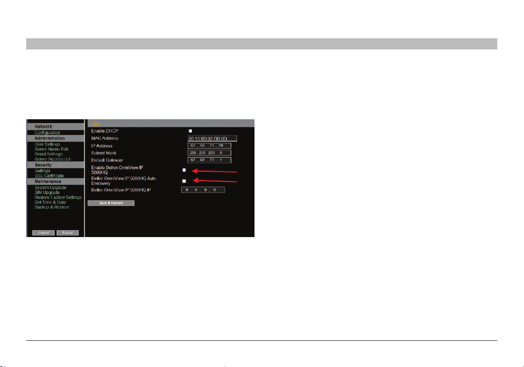
Set up the Belkin KVM-over-IP systems according to their user manuals’
instructions. In order to be managed by OmniView IP 5000HQ, all
Belkin KVM- over-IP devices must be configured to be OmniView IP
HQ-enabled. This is done from the “Network Configuration” page of
each K VM-over-IP device.
Figure 10 E nabling HQ for Om niView I P 5XX XG series
14
16
18
20 21
Also in the OmniView IP HQ section in Figure 10, specify how the
OmniView IP 50 00HQ server detects the IP device. This can be done
either by:
Manager Au to Discover y – When checked, OmniView IP 5000HQ
automatically detects the IP device if it resides on the same
network segment.
Manager IP – If the IP device resides on a different segment, type the
static IP address of the OmniView IP 5000HQ Manager. (We advise
typing the static IP addres s of the OmniView IP 5000HQ Manager even if
the IP device resides on the same network segment as the OmniView IP
5000HQ Manager.)
Install third-part y Access Service s according to their own installation
and configuration instructions. See the “Configuring Access Services”
section on page 55 for details required for the integration of the Access
Services into the OmniView IP 500 0HQ system.
Omni View IP 500 0 HQ
10
Page 15

SETTING UP THE SYSTEM
Table of Con tents
SECTIONS
1 3 5 7 9 11 13 15 17 192 4 6 8 10 12
7
4.1 Connecting the OmniView IP 5000HQ Manager
1. Connect the OmniView IP 5000HQ Manager to the network as follows:
On the rear panel, connect an Ethernet cable to LAN 1. Connect the
other end of the Ethernet cable to the network switch.
2. Connect the OmniView IP 50 00HQ Manager to a power supply outlet.
4.2 OmniView IP 5000 HQ Manager’s default IP address
Each OmniView IP 5000HQ Manager unit comes with the following
default values:
IP address - 192.168.2.200
Subnet mask - 255.255.255.0
G ate wa y - 19 2.16 8. 2.1
If these values are not suitable for your network, follow the steps in the
section below to display the OmniView IP 5000HQ interface. You can
then change the IP address of the OmniView IP 5000HQ Manager in the
“Network” tab under “Settings/Unit Maintenance”; see the “Network tab”
section on page 95.
14
16
18
20 21
4.2.1 Changing the OmniView IP 5000HQ Manager network parameters
®
1. Open your web browser (Internet Explorer
version 6.0 or higher).
2. Type in the IP address of the OmniView IP 5000HQ Manager (default IP
address https://192.168.2.200) and press “Enter”. (Change your
computer network settings, if necessary.) The login page appears.
3. Type the login name “admin” and password “SMBremote”.
4. Navigate to the “Network” tab under “Settings/Unit Maintenance” and
change the net work parameters to suit your network configuration.
5. Press “Save” and restart the OmniView IP 5000HQ Manager.
6. Wait for the system to restart and log in with the new IP address.
Omni View IP 500 0 HQ
11
Page 16
DISPLAYING THE OMNIVIEW IP 5000HQ WEB INTERFACE
Table of Con tents
SECTIONS
1 3 5 7 9 11 13 15 17 192 4 6 8 10 12
To display the web interface:
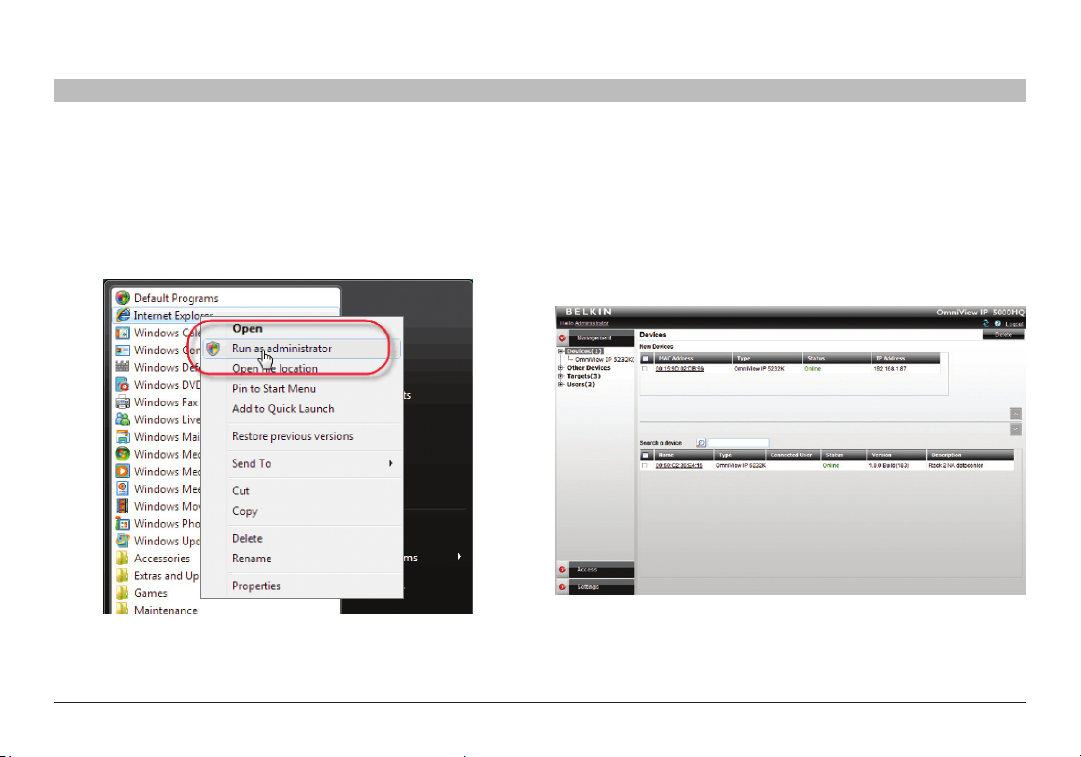
1. Open your web browser (Internet Explorer version 6.0 or higher).
Windows Vista Note! To log in to the web configuration interface with
Windows Vista, run Internet Explorer as Administrator. To do this,
right-click the Internet Explorer icon and select “Run as administrator”.
See figure below.
Figure 11 Run ning IE in Vist a
9
14
16
18
20 21
2. Type in the IP address of the OmniView IP 5000HQ Manager
(default IP address https://192.168.2.200) and press “Enter”.
Note! The IP address must begin with https:// and not http://. The login
page appears. Bookmark it for easy reference.
3. Type the login name and password. Default user name is “admin”
and password is “SMBremote”.
4. Press “Enter”. The web interface appears; see Figure 12.
Figure 12 D evices page
Omni View IP 500 0 HQ
12
Page 17
DISPLAYING THE OMNIVIEW IP 5000HQ WEB INTERFACE
Table of Con tents
SECTIONS
1 3 5 7 9 11 13 15 17 192 4 6 8 10 12
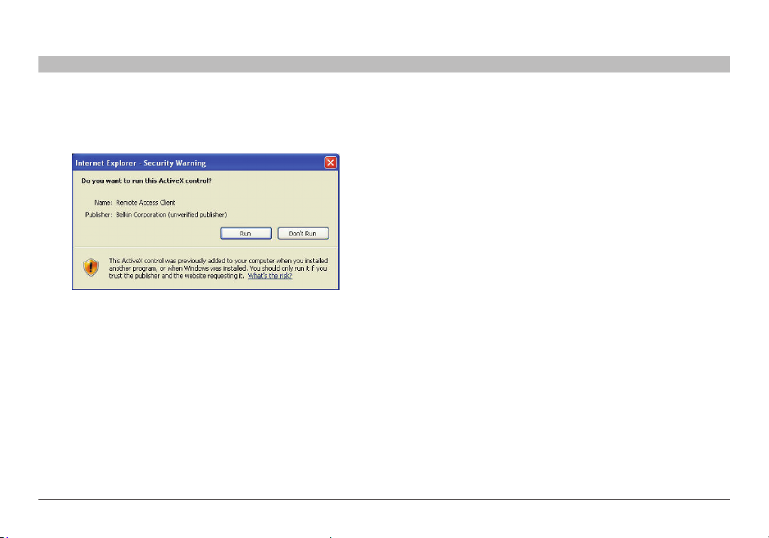
Note! On the first connection, the OmniView IP 5000HQ GUI prompts you
to install the OmniView IP 5000HQ client software; see Figure 13.
Click “Install”.
Figure 13 A ctiveX co ntrol ins tallation
9
14
16
18
20 21
5.1 Menu section
The menu section is on the left; see that Figure 12 is sub-divided into
three sections:
Management, which includes the configuration pages for IP devices,
targets, and users /groups.
Access, which contains acces s pages to all allowed targets and
target groups.
Settings, which contains t wo configuration sections: Application
and Maintenance.
This guide explains the menu sections from the point of view of first
setting up the system and then operating it.
The guide explains in the following order how to:
• CreateUsers
• ConfigureTargets
• ConfigureDevices
• ConfigureSettings
• ConfigureAccessServices
• AccesstheSystem
• ConfigureAdvancedSettings
Omni View IP 500 0 HQ
13
Page 18
CREATING USERS
Table of Con tents
SECTIONS
1 3 5 7 9 11 13 15 17 192 4 6 8 10 12
There are two possible methods of inputting users into the system.
When using local authentication (see page 44), users and groups
are created in the OmniView IP 5000HQ GUI. When using an LDAP
authentication server (see page 46), users and groups are imported
from a Windows Active Directory. With both authentication methods,
an administrator can grant users different access permissions as follows:
Administrator – An administrator can view, modify, manage, and
control all OmniView IP 5000HQ Manager configuration settings,
including creating new users.
User – A user cannot access or change any of the OmniView IP
5000HQ Manager configuration settings. When a user logs in, only the
targets to which the user has permission to access appear.
View Only – This user can only view permitted target screens without
keyboard and mouse control. A “view only” indicator appears on
the viewer’s local mouse pointer. View only has no effec t on
Access Services.
With local authentication, once you have created users you can form them
into groups. This makes management changes easier by, for example,
adding or deleting permitted targets per group rather than per individual
user. Creating groups is explained in the “Creating a user group” section
on page 19.
11
14
16
18
20 21
In LDAP mode, go to the “General tab” section below.
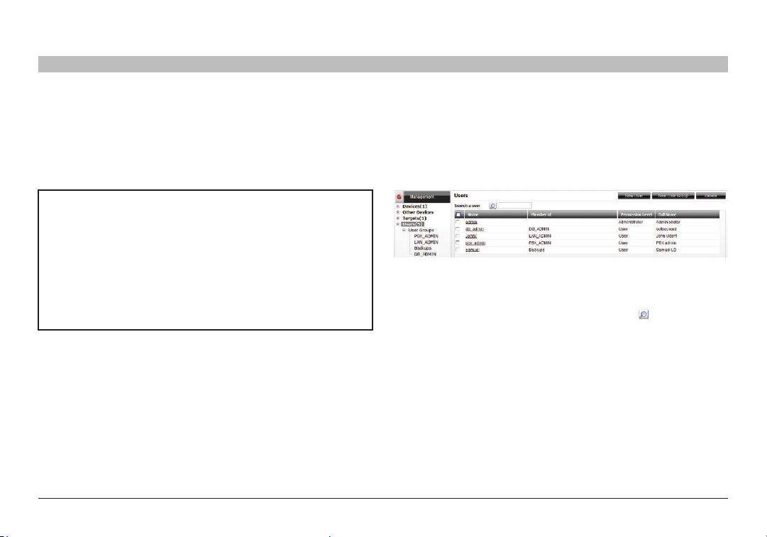
To create a new user (in local authentication mode):
1. From the “Management” menu, select “Users”. The “Users” page
appears showing the default administrator (admin) at the top of the list;
see Figure 14.
Figure 14 Us ers page
The columns show the following:
• Name – User’s login name. You can search for a user by typing the
login name in the “Search a user” field and clicking . You can sort
the names in alphabetical order A –Z or Z–A by clicking the top of the
“Name” column.
• Member of – Groups in which the user is a member.
• Permission Level – Administrator or user. You can sort the users
in permission-level order—administrators then users, or users then
administrators—by clicking the top of the “Permission Level” column.
• Description – Optional description.
Omni View IP 500 0 HQ
14
Page 19
CREATING USERS
Table of Con tents
SECTIONS
1 3 5 7 9 11 13 15 17 192 4 6 8 10 12
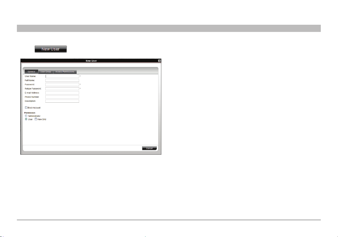
2. Click . The following appears.
Figure 15 C reating a New Use r – Gene ral Tab
11
14
16
18
20 21
6.1 General tab
Fill in the following details:
User Name – Type a login name. A user name cannot be identical to
any other existing User name. It can contain uppercase or lowercase
characters except for the following:
: ; ? & < > ”
A user name cannot include spaces.
Full Name – Type the user’s real name
Password/Retype Password – Type a password.
E-mail address/Phone Number/Description – These are optional fields.
Block Account – To prevent a user from entering the system, select
the “Block Account” check box. To re-enable the account, deselect the
check box.
Permission – Select the account type as outlined above on page 14.
Omni View IP 500 0 HQ
15
Page 20
CREATING USERS
Table of Con tents
SECTIONS
1 3 5 7 9 11 13 15 17 192 4 6 8 10 12
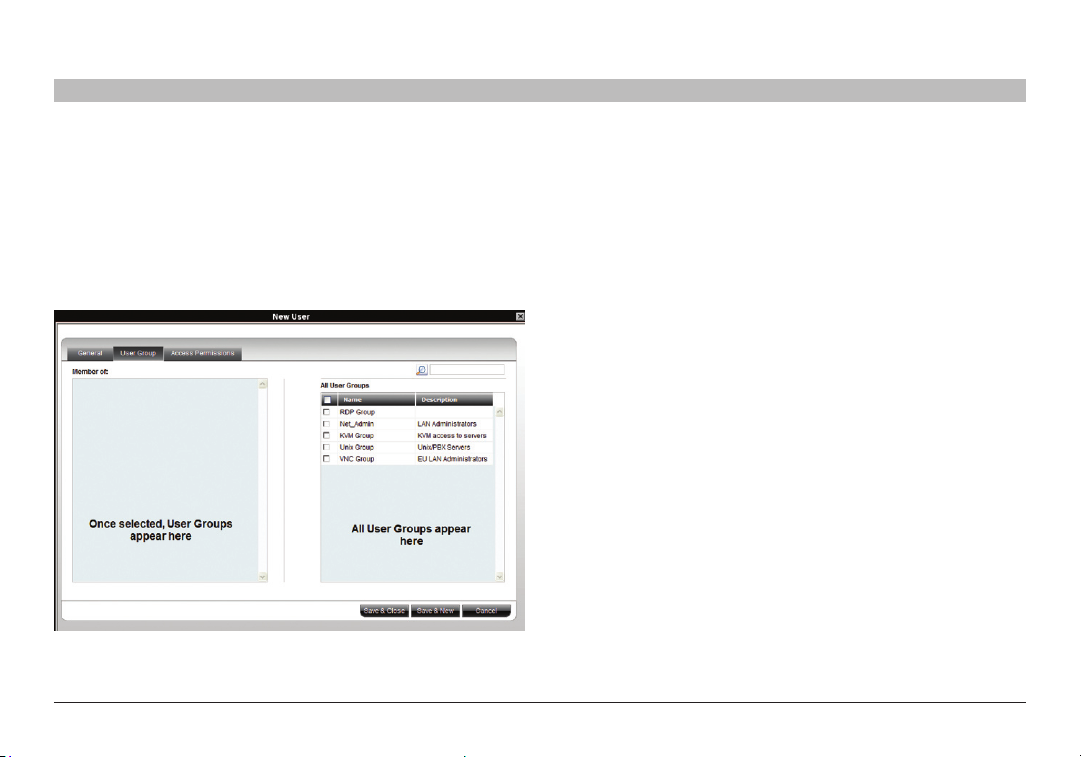
6.2 User Group tab
Once you have created users, you can put them into existing groups.
This gives users the access rights of that user group. The “Creating a
user group” section on page 19 explains how to create a user group.
To add a user to an existing user group or groups:
1. Press the “Users Group” tab; Figure 16 appears. All existing groups
appear in the “All User Groups” list.
Figure 16 N ew User Group t ab
11
14
16
18
20 21
2. Select the groups of which the new user will be a member.
The groups appear in the “Member of” list.
6.2.1 Removing users from a group
To remove use rs from a group:
In the “All User Groups” section, deselect the group’s check box. The
group is removed from the “Member of ” list.
Omni View IP 500 0 HQ
16
Page 21
CREATING USERS
Table of Con tents
SECTIONS
1 3 5 7 9 11 13 15 17 192 4 6 8 10 12
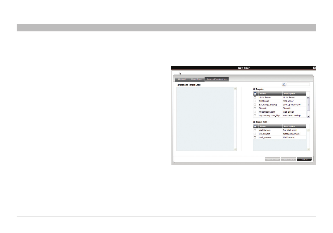
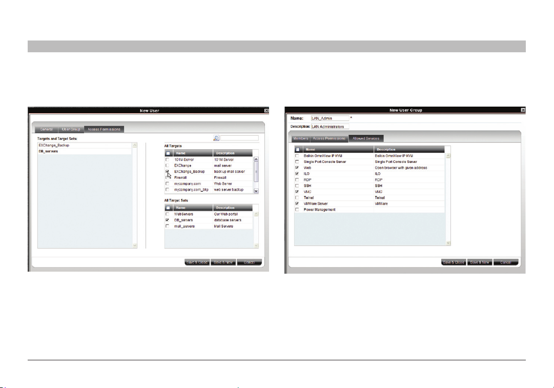
6.3 Access Permissions tab
You can choose which targets and target sets the user has permission
to access.
Notes:
• Ausercanhaveaccesstoatargetasanindividualuserorasa
group member.
• Auserorgroupofuserscanbeassociatedwithseveraltargetsets.
• WhenauserlogsintotheOmniViewIP5000HQwebinterface,
he sees only targets and target sets to which he has been associated.
See the “Accessing the System as a User” section on page 81.
11
14
16
18
20 21
To choose which targets/target sets the user will have access to:
1. Press the “Access Permissions” tab. The following appears.
Figure 17 Ne w User Ac cess Permiss ions tab
The “All Targets” and “All Target Sets” lists show the targets and all
target sets in the system.
2. Select the check boxes of the desired targets/target sets. They appear
in the “Targets and Target Sets:” list.
To disassociate a user/group from a target:
Deselect the targets/target sets check box from the relevant list.
Omni View IP 500 0 HQ
17
Page 22
CREATING USERS
Table of Con tents
SECTIONS
1 3 5 7 9 11 13 15 17 192 4 6 8 10 12
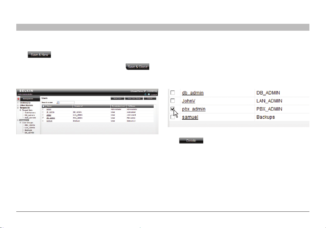
6.4 Saving a user
Click . The user’s details are now in the system.
Repeat this process to add more users. When finished, click .
All users appear on the “Users” page. The number of users appears in
brackets after “Users” in the menu; see Figure 18. User groups appear
as a sub-folder in the menu. Creating user groups is explained below.
Figure 18 L ist of users i n the system
By clicking a user name, an administrator can access the “General”,
“User Group”, and “Access Permissions” tabs of this user and change
any of the parameters.
11
14
16
18
20 21
6.4.1 Deleting a user
Deleting a user instantly removes the user’s authorization from the
OmniView IP 50 00HQ system and all IP devices.
To delete a user:
1. On the “Users” page select the check boxes of the users to be deleted.
2. Select or deselect all check boxes with one click.
Figure 19 D eleting a user
Click . The user’s details are now in the system.
Omni View IP 500 0 HQ
18
Page 23
CREATING USERS
Table of Con tents
SECTIONS
1 3 5 7 9 11 13 15 17 192 4 6 8 10 12
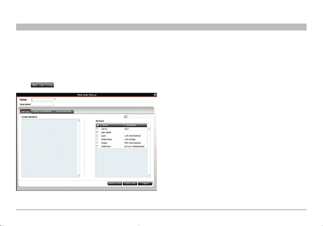
6.5 Creating a user group
Once you have created users, you can form them into groups. You then
give the same access permissions to the entire group without having to
go through the process for each individual user.
To create a user group:
1. From the menu, click “Users” or “User Groups”. On either of these pages,
click . The “New User Group” page appears; see Figure 20.
Figure 2 0 Creatin g a New User Gr oup – Mem bers tab
11
14
16
18
20 21
2. Name: Type a unique name for the group. You can add a description.
3. Select the check boxes of the users to be part of the group. They appear
in the “Group member s” list.
You can access the “User Properties” page by clicking a user name in
the “Group members” list.
Omni View IP 500 0 HQ
19
Page 24
CREATING USERS
Table of Con tents
SECTIONS
1 3 5 7 9 11 13 15 17 192 4 6 8 10 12
6.5.1 Access Permissions tab
Click the “Access Permissions” tab; Figure 20 appears.
Figure 21 Creating New Us ers – Access Permissions t ab
From the “All Targets” and “All Target Sets” lists, select the check
boxes of those to which the new user group will have permission to
access. When selected, the target/set appears in the “Targets and
Target Sets” list.
To remove targets/sets, deselect the che ck boxes.
11
14
16
18
20 21
6.5.2 Allowed Services tab
Click the “Allowed Services” tab. The following appears.
Figure 2 2 Creati ng a New U ser Grou p – Allowed Ser vices tab
Here you can assign Access Services to group member s. If a group
member has permission to access a target, but there are no assigned
Access Services for the group, then the group member will not be able
to access the target.
Select the check boxes of all Access Services allowed to this group.
Omni View IP 500 0 HQ
20
Page 25
CREATING USERS
Table of Con tents
SECTIONS
1 3 5 7 9 11 13 15 17 192 4 6 8 10 12
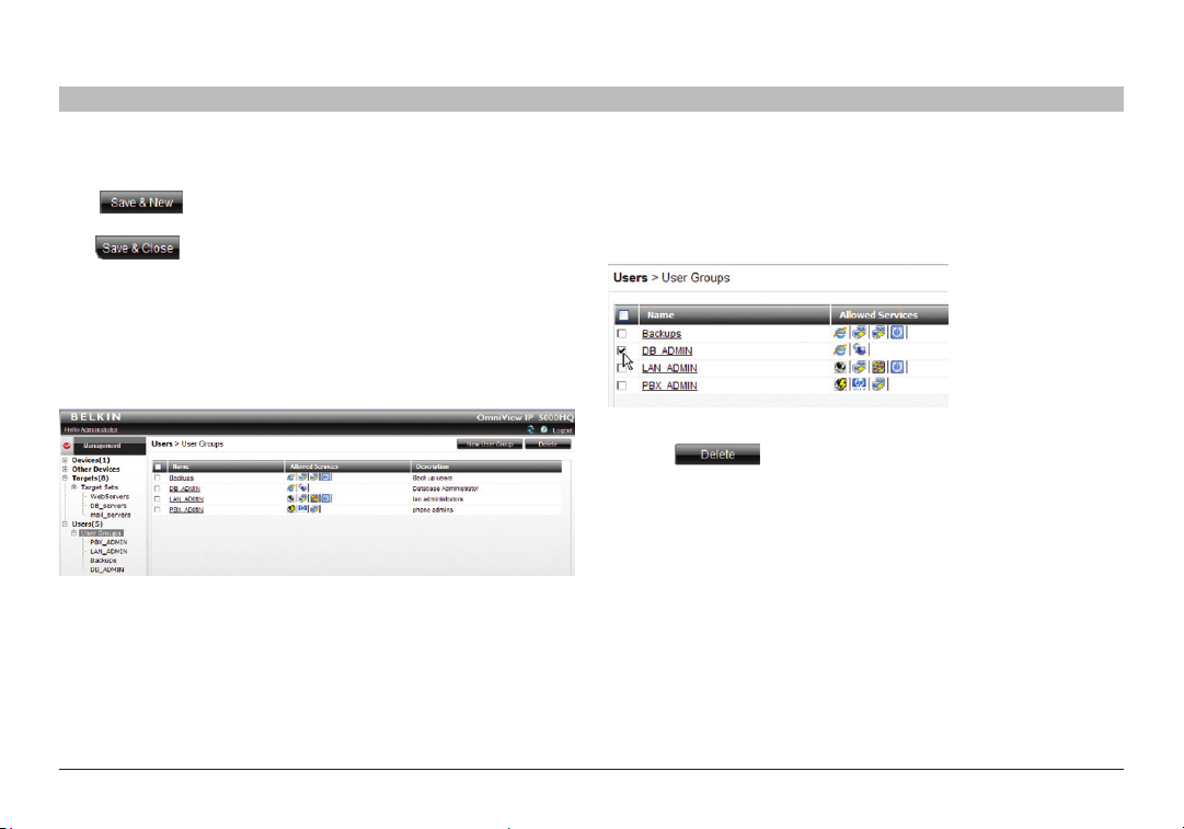
6.5.3 Saving the new group
Click . The group’s details are now in the system.
Repeat this process to add more groups. When finished,
click . All groups appear on the “User Groups” page;
see Figure 23.
Tip! The allowed services appear as icons. To see which ser vice the
icon represents, hold the mouse over the icon and a tool tip appears
with the name of the service.
You can create different access profiles. You can give permission
to targets and define different access rights through the
“Allowed Services”.
Figure 2 3 User G roups pag e
11
14
16
18
20 21
6.5.4 Deleting a user group
To delete a group:
1. On the “Users Group” page, select the check boxes of the groups to
be deleted.
Figure 24 Deleting a user group
2. Press . The groups are removed.
Note: Deleting a group will not delete the individual user s.
Omni View IP 500 0 HQ
21
Page 26
CONFIGURING TARGETS
Table of Con tents
SECTIONS
1 3 5 7 9 11 13 15 17 192 4 6 8 10 12
You must input the details of all the targets physically connected to the
system’s IP devices/KVM switches. This includes giving each target a
unique name and other relevant details.
As mentioned in the pre-installation guidelines, Appendix A (separate file
on this CD) contains three lists of all the details you need to prepare ( you
may not need all three).
To configure a target:
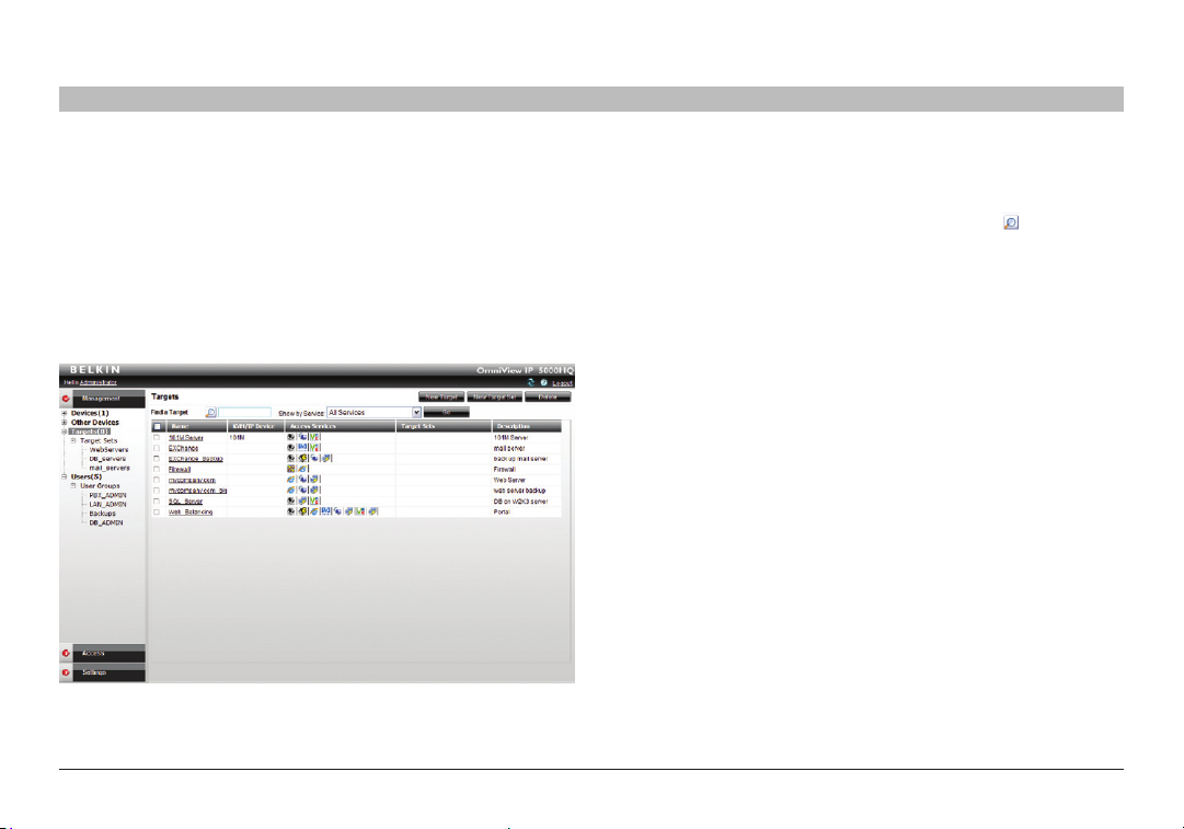
1. From the “Management” menu, select “Targets”. The “Targets”
page appears; see Figure 25.
Figure 25 List of existin g targets in th e system
13
14
16
18
20 21
The columns display the following information:
• Name – Name of target. You can search for a target by typing the
target name in the “Find a Target” field and clicking . You can sort
the names in alphabetical order A–Z or Z–A by clicking the top of the
“Name” column. You can also select which targets to display from
the “Show by Service” drop-down list. You can show all targets or
just show targets with a particular Access Service; to do so, choose
the desired service from the “Show by Service” drop-down list.
• KVM over IP Devic e – The type of Belkin OmniView K VM-over-IP
device to which the target is connected.
• Acces s Ser vices – Icons of Access Services available to acce ss
the target. To see which ser vice the icon represents, hold the mouse
over the icon and a tool tip appears with the name of the service.
• Target S ets – The target sets to which this target is a member.
• Description – Optional description of the target.
Omni View IP 500 0 HQ
22
Page 27
CONFIGURING TARGETS
Table of Con tents
SECTIONS
1 3 5 7 9 11 13 15 17 192 4 6 8 10 12
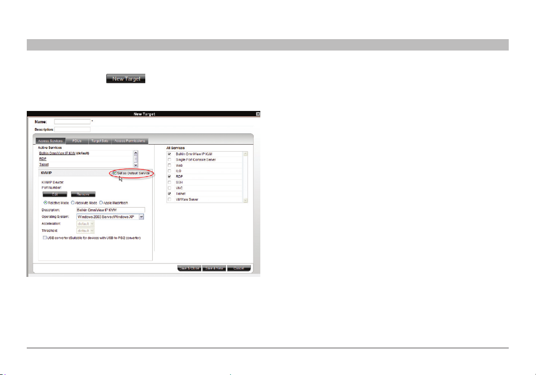
2. From the toolbar, click . The “New Target” page appears;
see Figure 26.
Name – Type a unique name for each server in the system.
Figure 2 6 Creatin g a New Target – Acc ess Servic es tab
13
14
16
18
20 21
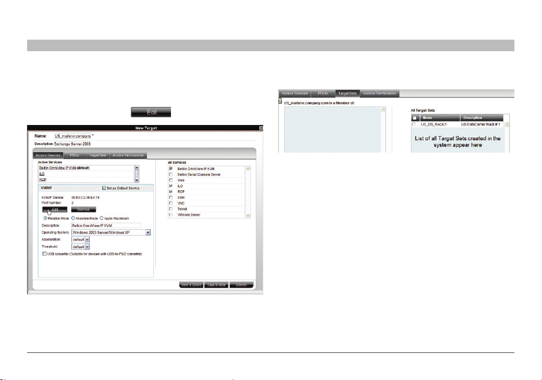
7.1 Access Services tab
Here you select and configure all Access Services relevant to this target.
All Services/Active Services: From the “All Services” list, select the check
box of all Access Services relevant to this target. Once selected, the service
appears in the “Active Services” list.
Note! Below discusses how to configure Belkin IP devices. Configuring
other Access Services is discussed in the “Configuring Access Services for
Individual Targets” section on page 67.
The pre-installation guidelines on page 3 explained what information you
need to configure each target.
7.1.1 Default Access Service
You can set any of the Access Services to be the default service. This
means that the service will be used to access the target by default when
selecting the target by clicking its name. To access the target via a different
service, the service must be selected. To set a service as the default,
display the service as explained below and select the “Set as Default
Service” check box, circled in Figure 26.
Omni View IP 500 0 HQ
23
Page 28
CONFIGURING TARGETS
Table of Con tents
SECTIONS
1 3 5 7 9 11 13 15 17 192 4 6 8 10 12
7.1.2 Belkin OmniView KVM Switch
KVM/IP Device/Port Number: Assign the IP device and KVM switch port
number (where relevant) to which this target is physically connected.
On the “New Target” page, click .
Figure 27 Assigning K VM por t to a tar get
13
14
16
The “Assign Device” window appears; see Figure 28.
Figure 28 Assign Devic e window
18
20 21
Omni View IP 500 0 HQ
24
Page 29
CONFIGURING TARGETS
Table of Con tents
SECTIONS
1 3 5 7 9 11 13 15 17 192 4 6 8 10 12
3. From the list, expand the device type to which the target is connected
and select the actual device the target is connected to; see Figure 29.
Figure 2 9 Assig ning tar gets to de vices
4. Double-click the port number row to which the target is connected.
The name of the target appears in that row.
5. Click “Save”. The changes are saved and the “New Target” page
reappears, showing the assigned IP device and port number;
see Figure 30.
13
14
Figure 3 0 KVM-over-IP D evice / Port n umber
16
18
To remove an assigned target from an IP device/KVM switch port,
click .
Figure 31 Removing current KVM port assign ment
The assignment is removed.
20 21
Omni View IP 500 0 HQ
25
Page 30
CONFIGURING TARGETS
Table of Con tents
SECTIONS
1 3 5 7 9 11 13 15 17 192 4 6 8 10 12
Other OmniView KVM-over-IP elements are as follows:
Description – Type a description for the target, e.g., backup server.
Operating System – Select the operating system of the target from
the drop-down list. The mouse parameter options adjust to match the
operating system.
Acceleration/Threshold – When the target’s mouse settings are not
default, select the appropriate values. Match the values to those of the
server’s mouse.
Note! For Windows XP, 2003 Server, Vista, and 2008 Server, go to the
mouse settings on the target and uncheck “Enhance pointer precision”.
USB Converter – When an IP device connects to a server via a USB-toPS/2 adapter, ROC/RICC USB, or X RICC USB or Specter USB, select
the “USB Converter” check box. The USB conversion affects the mouse
emulation and the “USB Conver ter” helps to synchronize the mouse.
®
Also, when an IP device is connected to a Linux
Converter” check box.
server, select the “USB
Absolute Mouse – Select the “Absolute Mouse” check box for a target
connected to USB, which has a Windows Me or later operating system.
See the “Configuring Access Services for Individual Targets” section on
page 67 to configure other Access Services.
13
14
16
18
20 21
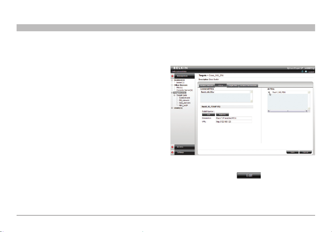
7.2 PDU tab
Here you configure IP PDU to allow power on, power off, or to power-cycle
the target.
Figure 3 2 Assig ning power outlet to targ et
Make the selection from the list of all PDUs on the right of the box.
The PDU will appear in the “Connected PDUs” list. Next, you have
to assign the outlet number. Click and assign the outlet by
double-clicking on the appropriate outlet row.
Omni View IP 500 0 HQ
26
Page 31

CONFIGURING TARGETS
Table of Con tents
Figure 3 3 Power outlet to target selec tion
SECTIONS
1 3 5 7 9 11 13 15 17 192 4 6 8 10 12
Click and the outlet number will appear.
Click .
13
14
Figure 3 4 Current powe r-outlet s electio n
16
18
20 21
Omni View IP 500 0 HQ
27
Page 32

CONFIGURING TARGETS
Table of Con tents
SECTIONS
1 3 5 7 9 11 13 15 17 192 4 6 8 10 12
7.3 Target Sets tab
Creating target sets is explained in the “Creating a target set” section on
page 29. Once you have created target sets, you can put targets into target
sets, giving access rights to all targets in a set to all members.
1. Press the “Target Sets” tab. The following appears.
Figure 3 5 Current Target S ets tab
2. From the “All Target Sets” list, select the check boxes of the target sets
to which you want the target to be associated. The target set appears
in the “Is a Member of” list.
13
14
16
18
20 21
7.4 Access Permissions tab
You can choose which users and groups can have access permission to
the target.
Press the “Access Permissions” tab. The following appears.
Figure 3 6 Current Acce ss Permissio ns tab
All existing users appear in the “All Users” list. All groups appear in the
“All Groups” list.
To choose which users/groups have access to the target:
1. Select the check boxes of the users or groups. They appear in the
“Users and Groups:” list.
To disassociate a user/group from a target:
Deselect the user/group check box from the relevant list.
Omni View IP 500 0 HQ
28
Page 33

CONFIGURING TARGETS
Table of Con tents
SECTIONS
1 3 5 7 9 11 13 15 17 192 4 6 8 10 12
7.5 Saving the target
Click . The target details are now in the system.
Repeat this process to input all connected servers. When finished,
click . All targets appear on the “Targets” page; see Figure 25.
7.6 Deleting targets
You can remove targets from the system as follows:
From the “Targets” page, select the check boxes of the targets to be deleted.
Press .
7.7 Creating a target set
You can group targets into sets, e.g., make a set of all financial servers in
the system. You can then give users access rights per the target set rather
than per individual targets. Target sets appear as a Favorites folder for
users on the “Access” page.
To create a new target set:
1. From the “Targets” page, click . The following appears.
13
14
Figure 37 Creating New Targe t Set – Targets ta b
16
18
20 21
2. Name – Type a unique name for the target set.
3. Description – Type a description.
4. From the “All Targets” list, select the check boxes of the targets
you want to add to the target set. The targets appear in the
“Assigned Targets” list.
Omni View IP 500 0 HQ
29
Page 34

CONFIGURING TARGETS
Table of Con tents
SECTIONS
1 3 5 7 9 11 13 15 17 192 4 6 8 10 12
7.7.1 Access Permissions tab
You can choose which users and groups can have access permissions to
the target set.
Press the “Access Permissions” tab. The following appears.
Figure 3 8 Creating New Target Sets – Acces s Permis sions ta b
13
14
16
18
20 21
All existing users appear in the “All Users” list. All groups appear in the
“All Groups” list.
To choose which users/groups have access to the target set:
1. Select the check boxes of the users or groups. They appear in the
“User s and Groups:” list.
To disassociate a user/group from a target set:
Deselect the user/group check box from the relevant list.
7.7.2 Saving the target set
Click . The target set details are now in the system.
Repeat this process to add more target sets. When finished,
click . All target sets appear in the menu under “Targets/
Target Sets” and also on the “Target Sets” page. From the menu, select
“Targets/Target Sets”; see Figure 39.
Figure 3 9 Current Target s ets in the syste m page
Omni View IP 500 0 HQ
30
Page 35

CONFIGURING TARGETS
Table of Con tents
SECTIONS
1 3 5 7 9 11 13 15 17 192 4 6 8 10 12
To see all the targets in a target set, click the target set name either from
the menu or on the page; see Figure 40. From this page you can at any
time assign or remove targets from the target set. From the “Access
Permissions” tab, you can choose which users and groups can have
access permissions to the target set. You can access target properties by
clicking a target name in the “Assigned Targets” list.
Figure 4 0 Editing a tar get set
13
14
16
18
20 21
7.7.3 Deleting a target set
You can delete a target set from the “Target Sets” page:
1. Select the check boxes of the target set to be deleted.
Figure 41 D eleting a target set
2. Press . The target set is removed. Note: Deleting a target set
will not delete the individual targets.
Omni View IP 500 0 HQ
31
Page 36

MANAGEMENT
Table of Con tents
SECTIONS
1 3 5 7 9 11 13 15 17 192 4 6 8 10 12
8.1 Devices
The web interface opens at the “Devices” page; see Figure 42.
The “New Devices” section automatically displays all KVM IP devices
detected by the OmniView IP 5000HQ system. (For KVM IP devices to
appear, they must be configured to be HQ enabled—see the “Setting
each OmniView KVM-over-IP Switch to be OmniView IP 5000HQ enabled”
section on page 36.) Each device appears identified by its MAC address.
The MAC address of each IP device is written on a sticker on the unit’s
underside. Once the device is configured by giving it a name, it then only
appears in the “Devices” section. The “New Devices” section itself only
appears when there are new devices detected.
Figure 4 2 Curren t KVM D evices p age
14
18
20 21
16
15
The columns on the “Devices” page display the following information:
Name – Once IP devices are given an identifying name, they appear here.
Typ e – Connected IP device type.
Connected User – User currently operating the remote session.
Status
Under the “Status” column, there are the following possibilities:
Online – The device is up and running and is ready to be configured, or is
available for a remote session.
Alarm – Device is down and is unavailable for a remote session.
Warning – Problem with the device. See the “Devices” page on the left for
more information.
Uploading – Device is receiving new firmware from OmniView IP
5000HQ Manager.
Updating device – Device is receiving an updated configuration from
OmniView IP 5000HQ Manager.
Rebooting – Device reboots upon any network parameter change or
firmware upgrade.
Connecting – OmniView IP 5000HQ sends or receives the Device
Discovery message.
Vers ion – Displays the device firmware version number.
Description – Identifying description of the device as input by the
administrator when configuring the device.
Omni View IP 500 0 HQ
32
Page 37

MANAGEMENT
Table of Con tents
SECTIONS
1 3 5 7 9 11 13 15 17 192 4 6 8 10 12
8.2 Other Devices
Clicking on “Other Devices” under the management tab will allow choosing
between power distribution units (PDUs) and console servers.
Note: In order to use PDUs and console servers, these devices have to be
configured under “Settings — Attached Devices” (please see page 51).
Figure 4 3 Current “Ot her Devic es”
14
18
20 21
16
15
8.2.1 Other Devices – PDU
Select “Power Distribution Units” and the following screen with the current
PDUs will appear.
Figure 4 4 Current PDUs
To add a new PDU, click . The “New PDU” dialog window
appears. Enter all PDU-related information.
Omni View IP 500 0 HQ
Figure 4 5 Adding new PDU s – Gene ral tab
33
Page 38

MANAGEMENT
Table of Con tents
SECTIONS
1 3 5 7 9 11 13 15 17 192 4 6 8 10 12
Next, configure the PDU’s power outlets according to the physical
connection to the server or other equipment by clicking on
the tab.
Figure 4 6 Adding new PDU s – Outle ts tab
14
18
20 21
16
15
Drag the target name from the right side’s current targets list to the left
side’s corresponding power outlet. Double-click on the target name on the
right side to remove the selection. Repeat for each power outlet, and click
when you’re done. Your PDU has been configured and the
power option ( ) becomes available from the “Access” tab.
Figure 47 P erform ing power commands
The following commands can be per formed from the HQ interface.
Figure 4 8 Power command s
To cancel, click .
Omni View IP 500 0 HQ
34
Page 39

MANAGEMENT
Table of Con tents
SECTIONS
1 3 5 7 9 11 13 15 17 192 4 6 8 10 12
8.2.2 Other Devices – Console Server
Select “Console Server” from “Management > Other Devices” and the
following screen with the current console servers will appear.
Figure 4 9 Current cons ole servers in the system
To add a new console server to the setup, click .
The “New Console Server” dialog window appears. Enter all console
server-related information.
14
Figure 5 0 Adding new con sole server s – General ta b
18
20 21
16
15
Next configure the console server’s serial connections according to the
physical connection to the server or other equipment by clicking on the
tab.
Omni View IP 500 0 HQ
35
Page 40

MANAGEMENT
Table of Con tents
SECTIONS
Figure 51 A dding new console ser vers – Serial tab
1 3 5 7 9 11 13 15 17 192 4 6 8 10 12
Drag the target name from the right side’s current targets list to the left
side’s corresponding serial port. Double-click on the target name on the
right side to remove the selection. Repeat for each power outlet,
and click when you’re done. Your console server has been
configured and the console server ( ) becomes available from the
“Access” tab.
14
Figure 5 2 Using c onsole s ervers
18
20 21
16
15
8.3 Setting each OmniView KVM-over-IP Switch to be OmniView IP
5000HQ-enabled
In order to be managed by OmniView IP 5000HQ, all Belkin KVM IP devices
must be configured to be HQ. See the “Setting Up the System” section on
page 10.
Tip! Since KVM IP devices only appear in the “New Devices” list once they
are HQ-enabled, make each KVM IP device HQ-enabled in a certain order
with a suitable time gap, so that you can identify the unit’s location.
Omni View IP 500 0 HQ
36
Page 41

MANAGEMENT
Table of Con tents
SECTIONS
1 3 5 7 9 11 13 15 17 192 4 6 8 10 12
8.4 Configuring the KVM IP devices in the OmniView IP 5000HQ
Configure a new KVM IP device as follows:
1. In the “New Devices” section, click the MAC address of a KVM IP device.
The “General” tab of the “Devices” page appears; see Figure 53.
Figure 5 3 KVM-over-IP D evices page – General tab
Typ e – KVM IP device type, OmniView IP 5232K, etc. (read-only field).
Name –You must assign a unique name to each IP device before
associating connected targets or KVM switches. Type a name for
the device.
Description – These are optional fields used for device identification.
14
18
20 21
16
15
Status – This is the connection status.
Device Info – Contains information about the device, including its
operational status and version numbers of firmware, KME (keyboard,
mouse emulation), hardware, SDF (switch definition file), and date and time
of last configuration update.
8.4.1 The Advanced button
When required, you can change the performance and mouse settings
(the “Set mouse and performance from KVM over IP Session” must be
unchecked on the “Settings/Global Settings” page—see the “OmniView IP
5000HQ session idle time-out” section on page 50).
To do so:
Press . The following appears:
Figure 5 4 KVM-over-IP d evice – Advance d page
Omni View IP 500 0 HQ
37
Page 42

MANAGEMENT
Table of Con tents
8.4.2 Performance
Bandwidth has the following options from the drop-down menu:
High
For optimal performance while working with a local area (LAN) connection,
select “High” bandwidth. This will adjust the performance to low
compression and high color (16-bit).
Low
For optimal performance when using a dial-up connection, select “Low”
bandwidth. This will adjust the performance to high compression and 16
colors. For improved performance, verify that the “Color” selection is a
16-color palette.
Medium
When working on DSL, cable, or ISDN connections, select “Medium”.
Custom
Custom gives you the option to manually choose both the compression
and colors.
SECTIONS
1 3 5 7 9 11 13 15 17 192 4 6 8 10 12
14
8.4.3 Mouse
Select the appropriate values according to the type of mouse connected to
the device.
Typ e – Select the mouse type you would like the IP device to emulate.
When setting the mouse emulation type, set it to match the mouse
connected to the local console port on the IP device, e.g., if the local mouse
is a 2-button mouse, but not from Microsoft, set the mouse-emulation type
to “Standard Mouse” and uncheck the “Microsoft” check box.
Tip! The mouse on most KVM drawers in a standard rack is a standard
mouse.
Microsoft – Uncheck this box if the mouse does not work using Microsoft
mouse protocol.
Important!!
We recommend not changing the Advanced settings unless
there is erratic mouse behavior. For example, the mouse makes
random clicks and jumps arbitrarily around the screen.
Press “Apply” to save changes and return to the
“Device Properties” page.
18
20 21
16
15
Omni View IP 500 0 HQ
38
Page 43

MANAGEMENT
Table of Con tents
SECTIONS
1 3 5 7 9 11 13 15 17 192 4 6 8 10 12
8.5 KVM Ports tab
In the “KVM Ports” tab, you:
• AssociatetheKVMswitchesinthesystemtotherelevantIPdevice.
• AssociatetargetswiththerelevantIPdevice/portnumberonthe
KVM switch.
Click the “KVM Ports” tab, the following appears.
Figure 5 5 Configuring KVM over IP – K VM Ports ta b
14
18
20 21
16
15
The KVM switch drop-down list consists of pre-selected KVM switches.
You must select all the KVM switch types physically connected to the
system; this is done in the “Settings” part of the menu and is explained
in the “KVM switches” section on page 52. Select the KVM switch model
(if any) physically connected to this IP device. The number of ports in the
selected KVM switch appears in the “Ports” section.
Notes:
When using an OmniView 5216/32K Switch, “Internal” is selected by default
and cannot be altered.
Omni View IP 500 0 HQ
39
Page 44

MANAGEMENT
Table of Con tents
SECTIONS
1 3 5 7 9 11 13 15 17 192 4 6 8 10 12
8.6 Targets
The targets you created appear in the “Targets” list.
You can choose to display all targets or just unassigned targets (default), or
targets belonging to a target set. Select the desired option from the “Show
Targets” drop-down menu.
You must associate the targets with the relevant IP device or with the port
number s on the KVM switch to which they are physically connected.
To associate the targets:
1. From the “Targets” list, double-click the target connected to port #1
of the KVM switch. The target assigns to port #1 of the “Ports” section.
Alternatively, drag and drop the target to the correct por t number.
2. Repeat the above step for all targets connected. Ensure the right target
assigns to the correctly numbered port.
To remove a target from a port:
Double-click the target in the “Ports” section. The target name moves to
the “Target” section and is now unassigned.
Note! Deleting a target removes its association with the KVM port number.
14
18
20 21
16
15
8.7 Network tab
In the “Network” tab, you configure and modify network parameters of the
IP device.
Click the “Network” tab. The following appears.
Figure 5 6 KVM-over-IP D evice – Networ k tab
Interface I displays the IP address of the KVM-over-IP device as discovered
by the OmniView IP 5000HQ Manager system. You can change this
address here.
Enter IP address, subnet mask, and default gateway for the network
adapter, as given by your network administrator.
In “TCP Ports”, type three ports (from 800 and up to 65535). By default the
port numbers are 900, 901, and 902. These default ports are suitable for the
majority of installations.
Omni View IP 500 0 HQ
40
Page 45

MANAGEMENT
Table of Con tents
SECTIONS
1 3 5 7 9 11 13 15 17 192 4 6 8 10 12
Click to clear or select the following according to your requirements:
DHCP – Enable DHCP to provide you with dynamic IP addressing for the IP
device, if a DHCP ser ver exists.
Note: Any change in the network configuration forces the IP device
to restart.
8.8 Saving the KVM-over-IP device configuration changes
Press “Save” to save the settings and configure the IP device. The K VMover-IP device is upgraded to the device firmware stored in the OmniView
IP 5000HQ system. It receives the SDF from the OmniView IP 5000HQ
system and also a list of targets, users, and their permissions (CFG). The
KVM-over-IP device may be unavailable during the upgrade and while
receiving the CFG and SDF updates.
8.9 Deleting KVM-over-IP devices
IP devices can be deleted from the OmniView IP 5000HQ system from the
“Devices” page.
To delete IP devices:
1. From the “Management” menu, click “Devices” and the “Devices”
page appears.
2. Select the check boxes of the units to be deleted, or select the top
check box to select or deselect all check boxes.
3. Click . The devices are deleted.
4. Uncheck “Enable HQ” on the device’s “Network Configuration”
web page. This will prevent the deleted KVM IP device from
being rediscovered.
14
18
20 21
16
15
8.10 Device discovery
The status of the KVM IP devices is updated automatically every minute.
You can manually discover new devices at any time from the
“Devices” page.
To do so:
In the menu, right-click “Devices” and the “Discovery” menu appears;
see Figure 57. Click “Discover Now”. The OmniView IP 5000HQ Manager
performs a device discovery on the network segment. All newly discovered
devices appear in the “New Devices” section.
Figure 57 Devices page – New Devices di scovery
Omni View IP 500 0 HQ
41
Page 46

SETTINGS – APPLICATIONS
Table of Con tents
SECTIONS
1 3 5 7 9 11 13 15 17 192 4 6 8 10 12
From the menu, click “Settings”. The settings are split into “Applications”,
“Attached Devices”, and “Maintenance” sections.
In the “Applications” section, you configure:
• AccessSer vices
• AccountPolicy
• GlobalSettings
9.1 Access Services
Besides connecting to Belkin OmniView IP devices, you can connect
to a variety of both hardware and software external resources from the
OmniView IP 5000HQ interface as follows:
• WebService
• IP-EnabledPowerDistributionUnits
• ConsoleServers
• ILO-HPIntegratedLights-Out(iLO)
• RDP-RemoteDesktopProtocol
• SSH-SecureShell
• VNC-VirtualNetworkComputing
• Telnet-TELecommunicationNETwork
• VMwareServer
See pages 57-64 for an elaboration of the above services.
From the “Access Services” page you can configure Access Services
for targets in the system. You can also add new Access Services from
this page.
16
14
Figure 5 8 Settings – A ccess S ervice s
17
18
Outlined below are the default template values for Belkin IP devices.
If these values are not suitable, you can change them.
For the default template values of the other factory-included Access
Services, see the “Configuring Access Services” section on page 55.
20 21
Omni View IP 500 0 HQ
42
Page 47

SETTINGS – APPLICATIONS
Table of Con tents
SECTIONS
1 3 5 7 9 11 13 15 17 192 4 6 8 10 12
9.1.1 Belkin OmniView IP KVM
Click “Belkin OmniView IP KVM”. The Belkin OmniView IP KVM settings
appear; see Figure 59.
Figure 5 9 Belkin OmniView IP K VM settings
The default elements of the Belkin OmniView IP K VM set tings are
as follows:
Note! Only change the default settings if the large majorit y of
the t argets in the system have s ettings that are diffe rent to the
default settings.
16
14
17
18
20 21
Description – This is the description of the Access Service -
Belkin OmniView IP K VM device.
Operating System – Default operating system is Windows 2003 Server/
Windows XP. This setting is suitable for Windows XP, Vista, 2003 Server,
and 2008 Server. If the large majority of the targets in the system have a
different operating system, select it from the drop-down list. The mouse
parameter options adjust to match the operating system.
Acceleration/Threshold – When the target’s mouse settings are not
default, select the appropriate values. Match the values to that of the
server’s mouse.
Note! For Windows XP, 2003 Server, Vista, and 2008 Server, go to the
mouse settings on the target and uncheck “Enhance pointer precision”.
USB Converter – When a KVM-over-IP device connects to a server via a
USB-to-PS/2 adapter, RICC/ROC USB, or X RICC USB or Specter USB,
select the “USB Converter” check box. The USB conversion affects the
mouse emulation and the “USB Converter” helps to synchronize the mouse.
Omni View IP 500 0 HQ
43
Page 48

SETTINGS – APPLICATIONS
Table of Con tents
SECTIONS
1 3 5 7 9 11 13 15 17 192 4 6 8 10 12
9.2 Account policy
In Account Policy, you can choose either local or external authentication.
In local authentication, you define password and login complexity levels.
External authentication interfaces with the organizational Active Directory
server for user list importation.
In local authentication mode, the administrator creates users and groups
and assigns permissions via the OmniView IP 5000HQ interface. In LDAP
authentication mode, server option authentication is done through an LDAP
server. You import users and groups from the LDAP server.
To set these options:
From the “Application” menu, select “Account Policy”. The “Account Policy”
page appears; see Figure 60.
14
Figure 6 0 Account poli cy
16
17
18
20 21
Omni View IP 500 0 HQ
44
Page 49

SETTINGS – APPLICATIONS
Table of Con tents
SECTIONS
1 3 5 7 9 11 13 15 17 192 4 6 8 10 12
9.2.1 Password policy
When OmniView IP 5000HQ operates in local authentication mode,
choose the desired password policy. The different password policy
options are explained below.
Note! The following “special” characters: &, <, >, ”, cannot be used for
either the user name or password in any of the password levels.
Stri ct policy passwo rd:
• 8charactersormore
• Mustincludeatleast:
• 1digit,and
• 1uppercaseletter,and
• 1“special”characterasfollows:!.@#$%^*()_-+=[]{}
• Mustnotincludetheusername
Stan dard policy password:
• 6charactersormore
• Mustnotincludetheusername
Note:
You can write any character (except the “special” characters: &, <, >, ”)
and any number of characters for the password.
16
14
17
18
20 21
9.2.1.1 Accou nt blocking
You can block entr y into the system after a number of unsuccessful
attempts by a user inputting the wrong password.
To do so:
1. Select the “Account blocking” check box. The following appears.
Figure 61 Account block ing
Choose the number of attempts within a time period and for how long to
block the account.
Omni View IP 500 0 HQ
45
Page 50

SETTINGS – APPLICATIONS
Table of Con tents
9.2.2 Exter nal a uthentic ation (LDAP)
LDAP (Lightweight Directory Access Protocol) is a standard protocol for
accessing information in a directory.
LDAP defines processes by which a client can connect to an X.500compliant or LDAP-compliant directory service to add, delete, modify,
or search for information, provided the client has sufficient access rights
to the director y. For example, a user could use an LDAP client to query
a directory server on the network for information about specific users,
computers, departments, or any other information store d in
the directory.
Note! OmniView IP 5000HQ suppor ts Windows 2003 and Windows 2008
Active Directory LDAP Authentication.
9.2. 2.1 OmniView IP 5000HQ in ex ternal authentication (LDAP) mode
In external authentication (LDAP) mode, OmniView IP 5000HQ deletes all
users created before in local authentication mode. New users can only
be imported from a Windows 2003 or Windows 2008 Active Director y.
OmniView IP 50 00HQ will validate all user credentials against the
external LDAP server only.
Only the “admin” account remains as a “backdoor” account. This user
has OmniView IP 5000HQ local access. Admin account is allowed to
manage OmniView IP 5000HQ with “Administrator” access privileges.
However, “admin” is not permitted to connect to targets. This account
will allow changing OmniView IP 5000HQ to local authentication mode
at any time.
There is no direct access to any IP device. OmniView IP 5000HQ will act
as a gateway.
SECTIONS
1 3 5 7 9 11 13 15 17 192 4 6 8 10 12
16
14
Since the OmniView IP 5000HQ user accounts are kept in the local
database, some of the local accounts might not have related LDAP
objects (e.g., some user s’ accounts might migrate to another LDAP
path). To clean the local database from those ghost accounts that will
never pass LDAP authentication, OmniView IP 5000HQ provides the
customers with the manual synchronize operation.
User groups will not be deleted and will be managed locally after
its import.
When changing OmniView IP 5000HQ to local authentication mode, all
the users appear as “inactive.” To reactivate the users, the administrator
must explicitly provide each account with a local password.
9.2.2.2 DNS set ting in LDAP mode
Important! The correct DNS setting is vital for the successful
configuration of the OmniView HQ in LDAP mode. You set the HQ
DNS settings in the “Settings / Unit Maintenance / Network” tab.
See the “Network tab” section on page 95.
17
18
20 21
Omni View IP 500 0 HQ
46
Page 51

SETTINGS – APPLICATIONS
Table of Con tents
SECTIONS
1 3 5 7 9 11 13 15 17 192 4 6 8 10 12
9.2.2.3 LDAP sett ings
1. Select the “E xternal Authentication” tab and the LDAP settings
appear; see Figure 62.
Figure 6 2 LDAP setting s
2. Select the “Use LDAP authentication server” check box.
3. Input details of the Active Director y:
Base DN – Here you define the base object where the search for users
begins. The search is per formed only on this object and the objects
below it in the directory tree. The Base DN string has the standard LDAP
syntax:CN=(CommonName…),OU=(OrganizationalUnit),DC=(Domain
Component). Base DN should be in the following format DC=domain,
DC=tld. For example, for the domain kvm.belkin.org, the Base DN
should be DC=kvm,DC=belkin,DC=org.
Host – Type the host name or (preferably) the IP address of the Active
Directory DC server.
16
14
17
18
20 21
Port – Type the LDAP port number. If left blank, OmniView IP 5000HQ
uses the default LDAP port 389 (which is the default por t for most LDAP
servers including Microsoft Active Dire ctory).
Bind DN – Also known as “User DN” or “Append”. The Bind DN is
a distinguished name of an LDAP object, which ser ves a gateway
to the LDAP directory. Prior to sending the account/password pair,
OmniView IP 50 00HQ initiates a conversation handshake with LDAP.
This handshake protocol in ge neral needs a “Bind DN/Bind password”
pair to decide whether the OmniView IP 500 0HQ client is permitted to
query the LDAP directory server. (For example, if we have user John in
group Users in domain kvm.belkin.org, the Bind DN should look like this:
CN=John, CN=u sers,DC= kvm,DC=belkin,DC =org).
Type the Active Directory objects you would like to search and the user
account that will be used to perform this operation.
Password – Type the password for the user account given in the
Bind DN.
4. Click . The system queries the Active Directory.
(This may take some time.) The and buttons
become enabled.
9.2.2.4 Importing users
To import users, press and the “Import Users” window
appears. Here you see all the groups in the Active Directory.
To display the user s in a directory, expand the group.
Omni View IP 500 0 HQ
47
Page 52

SETTINGS – APPLICATIONS
Table of Con tents
Notes:
• Usersmustbemembersofgroupsinordertobeshowninthe
Import Users Active Director y tree. Users belonging to the container
“Users” in the Active Directory do not necessarily belong to any group.
• YoucanusetheActiveDirectorycommand“dsqueryuser”tolist
all Active Directory users with their correct Bind DN parameter s.
Run “dsquer y user” at the command prompt of your Active Directory
Domain Controller.
You can import:
• Agroupwithallitsusersbyselectingthegroup.
• Someusersofagroupbyexpandingthegroupandthenselecting
the desired users.
Once selected, the groups and users appear in the “Selected User
Group/User” area. Press “Save” and a prompt appears explaining
that all current 500 0HQ users will be deleted. Press “OK”. The groups
and users appear in the “Users/Groups” section of the OmniView IP
5000HQ, with the words “Users (LDAP mode)” at the top of the page.
After importing users, you must assign their permissions—administrator,
user, or view only. How to assign permissions is explained in the
“Creating User s” section on page 14. By default, all users have user
permission status. (Also, assign their target permissions and allowed
Access Services.)
SECTIONS
1 3 5 7 9 11 13 15 17 192 4 6 8 10 12
16
14
9.2.2.5 Synchronization
Synchronization does two things:
• KeepstheexactgroupstructuremaintainedontheLDAPservers.
(Whenever a user is added or removed from the LDAP server group,
it will be synchronized with the OmniView IP 500 0HQ).
• Removesdeletedusers.AuserthatresidesinOmniViewIP5000HQ,
but is deleted from the LDAP ser ver, will be removed from
OmniView IP 5000HQ as well.
Where users and/or groups have been added or deleted from the
LDAP database, you can synchronize the local user database with the
LDAP database. There is no need to import new users from the LDAP
database, synchronization does this automatically, provided that the
new user is added to one of the groups imported into the
OmniView IP 50 00HQ.
To synchronize:
Click . The local user database is compare d to the LDAP
database. Any local user that does not exist on the LDAP server is
noted as delete d. Any new user added to already imported OmniView IP
5000HQ groups in the LDAP database is noted as added.
Note: To add a user to the OmniView IP 50 00HQ groups using the
synchronize function, add this user to the imported group in the
LDAP server.
17
18
20 21
Omni View IP 500 0 HQ
48
Page 53

SETTINGS – APPLICATIONS
Table of Con tents
SECTIONS
1 3 5 7 9 11 13 15 17 192 4 6 8 10 12
9.2.2.6 Ope rating Om niView IP 500 0HQ in external
authent icat ion mode
In external authentication (LDAP) mode, OmniView IP 5000HQ Manager
will no longer allow login for the users that were created in local
authentication mode. These users will be deleted. New users will be
impor ted from Active Directory.
OmniView IP 50 00HQ Manager will validate all user credentials against
the LDAP server only.
Only the “admin” account retains local authentication as a “backdoor”
account. This user has OmniView IP 5000HQ local access. Admin
account is allowed to manage OmniView IP 5000HQ with “administrator”
access privileges. However, “admin” is not permitted to connect to
targets. This account will allow reversing the external authentication
mode at any time to local authentication mode.
There is no direct access to any IP device, even to its Configuration
page. OmniView IP 5000HQ will act as a gateway.
When changing OmniView IP 5000HQ to local authentication mode,
all imported users appear as “inactive.” To reactivate the user s, the
administrator must set a password for each account.
Clicking the “New User” button on the “Users” page opens the
“Impor t LDAP Users” window.
16
14
17
18
20 21
9.3 Global settings
In Global Set tings, you can change the idle time-out period and set out
global parameters as explained below.
From the menu, click “Global Settings” and the following appears.
Figure 6 3 Global Sett ings
Omni View IP 500 0 HQ
49
Page 54

SETTINGS – APPLICATIONS
Table of Con tents
9.3.1 Om niView IP 500 0HQ s ession idle time-out
Select the number of minutes of non-activity, after which the OmniView
IP 5000HQ sessions will terminate. The user will then have to re-log in.
Set mouse and performance from KV M/IP session
This check box determines who updates the local mouse and
performance settings. When checked, local mouse and performance
settings are determined at the remote session level. Deselecting this
option will apply default set tings to all devices. In order to change the
settings, the administrator must configure each device separately.
By selecting the check box, OmniView IP 5000HQ will not overwrite
local mouse and performance settings made in the client toolbar.
Allow all “Acc ess S ervices” for users without group assig nment
For users not assigned to any user groups, select the check box to
allow all “Access Services” by default. Deselecting this option prevents
access to any service for individual users that don’t belong to any group,
including administrators.
Default power command
For power management devices, you can select the default power
command from the drop-down list. Choose “Prompt”, “On”, “Off”,
or “Cycle”. The chosen command will be the default sent to the
connected device.
Items Per Page
Select the maximum number of items—targets, groups, etc.—to appear
on one page. When this number is reached, additional items are put on
another page. Click on the page link to open the next page.
Click “Save” to save changes.
SECTIONS
1 3 5 7 9 11 13 15 17 192 4 6 8 10 12
14
16
17
18
20 21
Omni View IP 500 0 HQ
50
Page 55

SETTINGS – ATTACHED DEVICES
Table of Con tents
SECTIONS
1 3 5 7 9 11 13 15 17 192 4 6 8 10 12
10.1 PDU
Configuring power distribution units (PDUs) is relevant when there are IP
PDUs connected to the system. You must select all IP PDU types
physically connected.
Note: Without configuring PDUs, you will not be able to perform any
power-related operations.
To select the PDU model t ypes:
1. From the “Attached Devices” menu, select “PDU”. A list of currently
supported models appears:
Figure 6 4 Power Distrib ution Un its
14
16
18
19
20 21
2. From the list, select the PDU brands and models physically connected
to your devices.
3. Press . The selection is saved.
10.1.1 Uploading a new PDU model
IfaPDUmodelisnotlisted,contactBelkinatsupport@belkin.comtoobtain
a new PDU definition file (SDF ).
When you receive the file, do the following:
1. Save the PDU model file on your computer’s hard disk.
2. Log in to OmniView IP 5000HQ as an administrator.
3. From the “PDU” page (see figure on the left), press
to locate the PDU model file (SDF.XML).
4. Press . The file uploads with the new switch type added
to the list.
5. Select the PDU model type and click .
Omni View IP 500 0 HQ
51
Page 56

SETTINGS – ATTACHED DEVICES
Table of Con tents
SECTIONS
1 3 5 7 9 11 13 15 17 192 4 6 8 10 12
10.2 KVM switches
Configuring KVM switches is relevant when there are analog KVM switches
connected to IP devices in the system. You must select all the KVM switch
types physically connected.
To select the KVM switch types:
1. From the “Attached Devices” menu, select “KVM Switches”.
A list of KVM switches appears; the columns show the following:
• Model – KVM switch model
• Manufacturer – KVM switch manufacturer
• Ports – the number of server ports
• Matrix – The number of simultaneous users this switch supports.
Note! If you know a KVM switch has matrix capabilities, but no number
appears in the “Matrix” column, contact the Belkin Support team to obtain
the updated SDF of the KVM switch. Uploading the SDF is explained in the
next section.
14
Figure 6 5 KVM Switche s
16
18
19
20 21
2. From the list, select the KVM switch brands and models physically
connected to your IP devices.
3. Press . The selection is saved.
Omni View IP 500 0 HQ
52
Page 57

SETTINGS – ATTACHED DEVICES
Table of Con tents
SECTIONS
1 3 5 7 9 11 13 15 17 192 4 6 8 10 12
10.2.1 Uploading a new KVM switch
IfaKVMswitchisnotlisted,contactBelkinatsupport@belkin.comto
obtain a new K VM switch definition file (SDF).
When you receive the file, do the following:
1. Save the KVM switch file on your computer’s hard disk.
2. Log in to OmniView IP 5000HQ as an administrator.
3. From the “KVM Switches” page, press to locate the
KVM switch file (SDF.XML).
4. Press . The file uploads with the new switch type added
to the list.
5. Select the KVM switch type and click .
14
16
18
19
20 21
10.3 Console ser ver
Configuring console servers is relevant when there are serial console
servers connected to the system. You must select all console server types
physically connected.
Note: Without configuring console servers, you will not be able to perform
any serial communication-related operations.
To select the console server model t ypes:
1. From the “Attached Devices” menu, select “Console Server”.
A list of currently supported models appears:
2. From the list, select the console server brands and models
Figure 6 6 Console Ser vers
physically connected to your serial devices.
3. Press . The selection is saved.
Omni View IP 500 0 HQ
53
Page 58

SETTINGS – ATTACHED DEVICES
Table of Con tents
10.3.1 Uploading a new serial console model
Ifaconsoleservermodelisnotlisted,contactBelkinatsupport@belkin.
com to obtain a new console server definition file (SDF).
When you receive the file, do the following:
1. Save the console server model file on your computer’s hard disk.
2. Log in to OmniView IP 5000HQ as an administrator.
3. From the “Console Servers” page (see figure on previous page),
press to locate the console server model file (SDF.XML).
4. Press . The file uploads with the new switch type added
to the list.
5. Select the console server model type and click .
SECTIONS
1 3 5 7 9 11 13 15 17 192 4 6 8 10 12
14
16
18
19
20 21
Omni View IP 500 0 HQ
54
Page 59

CONFIGURING ACCESS SERVICES – INTRODUCTION
Table of Con tents
SECTIONS
1 3 5 7 9 11 13 15 17 192 4 6 8 10 12
Each Access Service comes with a default settings template.
The template values can be changed from the “Settings/Access
Services” page; see Figure 67.
Figure 67 Access Ser vices
The template values are automatically applied to new targets that have
the Access Service assigned to them.
For example, there is a default value for the application path of an
Access Service. If this is suitable, ensure that all users have the Access
Service application in the same path on their computer. Where a user
computer has a different path, a prompt appears on the user’s computer
asking the user to browse for the Access Service application on
his computer.
Note! Access Service settings can also be changed, if necessary, for
individual targets (explained on page 67).
All the Access Ser vices are reached from the “Access Services” page;
see page 42.
14
16
18
20 21
11.1 Acces s Ser vices default values
Below are the factory-included Access Services and their default values.
If these values are not suitable, you can change them. If an Access
Service has an executable application, the application must be installed
on all local computers.
11.1.1 General note about application paths
When inputting the application path into the OmniView IP 5000HQ client
interface, you can include variables. For example, for an Access Service
called“ABCservice,”typing“%ProgramFiles%\ABCservice”caninstall
theapplicationinanydriveonclientcomputersintheProgramFiles\
ABCser vice folder.
The following variables in the application path can be used:
• %ProgramFiles%-ProgramFilesfolder
• %SystemRoot%\-Windowsfolder
Omni View IP 500 0 HQ
55
Page 60

CONFIGURING ACCESS SERVICES – INTRODUCTION
Table of Con tents
SECTIONS
1 3 5 7 9 11 13 15 17 192 4 6 8 10 12
11.1. 2 Belkin Serial Cons ole Serve r
Click “Single Port Console Server”. The Single Por t Console Server
settings appear; see Figure 68.
Figure 6 8 Single Port Console Ser ver sett ings
14
16
18
20 21
Description – Description of the Access Ser vice: Single Port
Console Server
URL/Host – IP address of Console Ser ver
Port – For Belkin Serial Console Server, TCP port number is 400 0.
Application – PuTTy.exe is application used and it must be installed on
all client computers; see the paragraph below.
The PuTTy application can be obtained from:
http://www.chiark.greenend.org.uk/~sgtatham/putty/download.html
Path – PuTTy application must be installed on all client computers,
preferablyinthesamepath.Inthedefaultpath%ProgramFiles%\PuTTy
(see Figure 68), the application could be in any drive in the Program
Files\PuTTyfolder.Seethegeneralnotesaboveaboutvariables.
Omni View IP 500 0 HQ
56
Page 61

CONFIGURING ACCESS SERVICES – INTRODUCTION
Table of Con tents
SECTIONS
1 3 5 7 9 11 13 15 17 192 4 6 8 10 12
11.1.3 Web
Click “ Web”. The web settings appear; see Figure 69.
Figure 6 9 Web Target
Description – Default description
Set the URL for each individual web page.
14
16
11.1.4 ILO
Click “ILO”. The ILO settings appear; see Figure 70.
Figure 70 ILO – SSH mode
18
20 21
Omni View IP 500 0 HQ
57
Page 62

CONFIGURING ACCESS SERVICES – INTRODUCTION
Table of Con tents
SECTIONS
1 3 5 7 9 11 13 15 17 192 4 6 8 10 12
Description – Description of the Access Ser vice - ILO
URL/Host – Type the URL/host of the ILO resource.
Port /Applicat ion/PuTTy Appl icat ion Path – These fields are only
relevant in SSH mode. The dif ference between SSH and Web mode is
detailed below.
SSH mode (d efault)
SSH mode uses an ILO console server. In SSH mode, the PuTTy
application must be installed on all client computers, preferably in the
samepath.Inthedefaultpath%ProgramFiles%\PuTTy(seeFigure70),
theapplicationcouldbeinanydriveintheProgramFiles\PuTTyfolder.
See the general notes above about variables.
The PuTTy application can be obtained from:
http://www.chiark.greenend.org.uk/~sgtatham/putty/download.html
In SSH mode, the port number is 22 (default).
Web mode
Web mode uses a remote console with power management options.
In Web mode, there is no need for an executable application. Figure 71
illustrates the ILO fields in Web mode.
14
Figure 71 ILO – Web mo de
16
18
20 21
Omni View IP 500 0 HQ
58
Page 63

CONFIGURING ACCESS SERVICES – INTRODUCTION
Table of Con tents
SECTIONS
1 3 5 7 9 11 13 15 17 192 4 6 8 10 12
Login Method:
• PromptforCredentials–ThismeanstheILOloginpageappears
and you log in manually.
• UseOmniViewIPHQCredentials–ThismeansOmniViewIP
500 0HQ logs in to ILO with the currently logged user credentials.
Ensure that ILO is configured to re cognize the same user name
and password.
• UsetheFollowingCredentials–Wheretheusernameandpassword
are different for OmniView IP 5000HQ and ILO, select this option.
User name and password fields appear. Type the ILO user name
and password. OmniView IP 5000HQ logs in to ILO using this
user name and password.
11.1.5 RDP
Click “RDP”. The following are the default settings for RDP.
Figure 72 RDP – Web mode
14
16
18
20 21
Description – Description of the access ser vice: RDP
URL/Host – Type the URL/host of the RDP resource.
Mode – RDP Client or Web. These are explained below.
Web mode (default)
Web mode uses a remote console with power management options. In
Web mode, there is no need for an executable application.
Scre en Size – Select the scre en size from the drop-down menu
Login Method:
• PromptforCredentials–ThismeanstheRDPloginpageappears
and you log in manually.
• UseOmniViewIPHQCredentials–ThismeansOmniViewIP
500 0HQ logs in to RDP with the currently logged user credentials.
Ensure that the target computer is configured to recognize the same
user name and password.
• UsetheFollowingCredentials–Wheretheusernameandpassword
are different for OmniView IP 5000HQ and the target computer,
select this option. User name and password fields appear.
Type the RDP user name and password. OmniView IP 50 00HQ logs
in to the target computer using this user name and password.
RDP Client mode
When selecting RDP Client mode, the page appear s as in Figure 73.
Omni View IP 500 0 HQ
59
Page 64

CONFIGURING ACCESS SERVICES – INTRODUCTION
Table of Con tents
SECTIONS
Figure 73 RDP – RDP Clie nt mode
1 3 5 7 9 11 13 15 17 192 4 6 8 10 12
RDP Client mode uses an RDP console ser ver. From Windows XP
onward, the executable application, mstsc.exe, comes as part of the
operating system. For Windows 2000, download the client por tion of the
remote desktop soft ware from the Microsoft website.
RDP Application Path – The RDP application must be installed on
all local computers, preferably in the same path. In the default path
%SystemRoot%\System32,theapplicationcouldbeinanydriveinthe
Windows\System32folder.Seethegeneralnotesaboveaboutvariables.
In RDP Client mode, there is only manual login.
14
16
18
11.1.6 SSH
Click “SSH”. The following are the default settings for SSH.
Figure 74 SS H
20 21
Omni View IP 500 0 HQ
60
Page 65

CONFIGURING ACCESS SERVICES – INTRODUCTION
Table of Con tents
SECTIONS
1 3 5 7 9 11 13 15 17 192 4 6 8 10 12
Description – Description of the access service: SSH
Application – PuTTy.exe is the application used for SSH access. The
PuTTy application can be obtained from:
http://www.chiark.greenend.org.uk/~sgtatham/putty/download.html
PuTTy Appl icat ion Path – PuTTy application must be installed on
all client computers, preferably in the same path. In the default path
%ProgramFiles%\PuTTy(seeFigure74),theapplicationcouldbeinany
driveintheProgramFiles\PuTTyfolder.Seethegeneralnotesabove
about variables.
URL/Host – Type the URL/host of the SSH resource.
Port – The SSH port number is 22 (default).
Login Method:
• PromptforCredentials–ThismeanstheSSHloginpageappears
and you log in manually.
• UseOmniViewIPHQCredentials–ThismeansOmniViewIP
500 0HQ logs in to SSH with the currently logged user credentials.
Ensure that SSH is configured to recognize the same user name
and password.
• UsetheFollowingCredentials–Wheretheusernameandpassword
are different for OmniView IP 5000HQ and SSH, select this option.
User name and password fields appear. Type the SSH user name
and password. OmniView IP 5000HQ logs in to SSH using this
user name and password.
14
16
18
20 21
11.1.7 VNC
Note! OmniView IP 50 00HQ currently supports RealVNC free edition
and other free VNC compilations ( TightVNC and UltraVNC).
Click “ VNC”. The following are the default settings for VNC.
Figure 75 VNC – VNC Clien t mode
Omni View IP 500 0 HQ
61
Page 66

CONFIGURING ACCESS SERVICES – INTRODUCTION
Table of Con tents
SECTIONS
1 3 5 7 9 11 13 15 17 192 4 6 8 10 12
Description – Description of the Access Service: VNC
Appl icat ion/ VNC Appl icat ion Path/Port – These fields are only
relevant in VNC Client mode. The dif ference between VNC Client and
Web mode is detailed below.
URL/Host – Type the URL/host of the VNC resource.
Mode – VNC Client (default)
When using VNC Client mode, the page appears (see Figure 75).
VNC Client mode uses a VNC console server. In VNC Client, the VNC
application must be installed on all client computers, preferably in the
same path. Type the path to the VNC Viewer application. Where the
VNCPath is the actual installation folder of the VNC application, the
installation folder depends on the type of VNC: RealVNC, TightVNC,
or UltraVNC. See the general notes above about variables.
The VNC application can be obtained from:
• RealVNC:http://www.realvnc.com
• TightVNC:http://www.tightvnc.com/
• UltraVNC:http://www.uvnc.com/
In VNC Client mode, the port numbe r should correspond to the VNC
listening por t.
Login Method:
• PromptforCredentials–ThismeanstheVNCloginappearsand
you log in manually.
• UseOmniViewIPHQCredentials–ThismeansOmniViewIP
500 0HQ logs in to VNC with the currently logged user credentials.
Ensure that VNC is configured to recognize the same password.
14
16
18
20 21
• UsetheFollowingCredentials–Wherethepasswordsaredif ferent
for OmniView IP 5000HQ and VNC, select this option. A password
field appears. Type the VNC password. OmniView IP 5000HQ logs in
to VNC using this password.
Web mode
In Web mode, there is no need for an executable application.
When selecting Web mode, the page appears as in Figure 76.
Figure 76 RDP – Web mode
In Web mode, there is only manual login.
Omni View IP 500 0 HQ
62
Page 67

CONFIGURING ACCESS SERVICES – INTRODUCTION
Table of Con tents
SECTIONS
1 3 5 7 9 11 13 15 17 192 4 6 8 10 12
11.1.8 Telnet
Click “Telnet”. The following are the default settings for telnet.
Figure 7 7 Telnet
14
16
18
20 21
Description – Description of the Access Service: Telnet
Application – PuTTy.exe is the application used for telnet access. The
PuTTy application can be obtained from:
http://www.chiark.greenend.org.uk/~sgtatham/putty/download.html
PuTTy Appl icat ion Path – PuTTy application must be installed on
all client computers, preferably in the same path. In the default path
%ProgramFiles%\PuTTy(seeFigure77),theapplicationcouldbeinany
driveintheProgramFiles\PuTTyfolder.Seethegeneralnotesabove
about variables.
URL/Host – Type the URL/host of the telnet resource.
Port – The telnet por t number is 23 (default).
Omni View IP 500 0 HQ
63
Page 68

CONFIGURING ACCESS SERVICES – INTRODUCTION
Table of Con tents
SECTIONS
1 3 5 7 9 11 13 15 17 192 4 6 8 10 12
11.1.9 VMware Server
Click “ VMware Server”. The following are the default settings for
VMware Server.
Figure 78 VMware Serve r
14
16
18
20 21
Description – Description of the Access Service: VMware Server
URL/Host – Type the host/IP of the VMware Server resource.
Application – vmware.exe is the application used for VMware Ser ver
access. The VMware Server Client application can be obtained from:
http://www.vmware.com/download/server/
Appl icat ion Path – VMware Server console must be installed on
all client computers, preferably in the same path. In the default path
%ProgramFiles%\VMware\VMwareSer verConsole(seeFigure78),the
applicationcouldbeinanydriveintheProgramFiles\VMware\VMware
Server Console folder. See the general notes above about variables.
Virtual Machine Path – Type the Vir tual Machine Path on the
VMware Server.
Login Method:
• PromptforCredentials–ThismeanstheVMwareServerConsole
login appears and you log in manually.
• UseOmniViewIPHQCredentials–ThismeansOmniViewIP
500 0HQ logs in to VMware Server Console with the currently logged
user credentials. Ensure that VMware Server is configured to
recognize the same user name and password.
• UsetheFollowingCredentials–Wheretheusernameandpassword
are different for OmniView IP 5000HQ and VMware Server, select
this option. User name and password fields appear. Type the
VMware Ser ver user name and password. OmniView IP 50 00HQ
logs in to VMware Server using this user name and password.
Omni View IP 500 0 HQ
64
Page 69

CONFIGURING ACCESS SERVICES – INTRODUCTION
Table of Con tents
SECTIONS
1 3 5 7 9 11 13 15 17 192 4 6 8 10 12
11.1.10 New Access Ser vices
You can add other Access Services. If the new service has an
executable application, the application must be installed on all client
computers, preferably in the same path.
Add new Access Services as follows:
1. From the “Access Services” page, click .
The “New Service” page appear s; see Figure 79. This page is a
template for configuring a new Access Service.
14
16
18
20 21
Fill in the fields that are relevant to the service as follows:
Name – Name of the Access Service
Description – Description of the Access Ser vice
URL – If the Access Ser vice resource can be reached via a web
browser, type the URL here: HTTP or HTTPS, etc. You may incorporate
variables into the URL as follows:
• %ProgramFiles%–ProgramFilesfolder
• %SystemRoot%\–Windowsfolder
• %IP%–IPaddress(“IP”checkboxmustbeselected)
• %Port%–TCPportnumber(“Por t”checkboxmustbeselected)
• %UserName%–Loginusername
• %Password%–Loginpassword(“LoginMethod”checkbox
must be selected)
Appl icat ion Path – If the new service has an executable application, the
application must be installed on all client computers, preferably in the
same path. The application could be in any drive in, e.g., the following
folder:%ProgramFiles%\Accessservice.Typetheapplicationpathand
executable name, including all command line switches, options, and
parameters.
IP – Where relevant, type the IP address of the Access Ser vice resource.
Port – Where relevant, type the por t number.
Omni View IP 500 0 HQ
Figure 7 9 New Ser vice page
65
Page 70

CONFIGURING ACCESS SERVICES – INTRODUCTION
Table of Con tents
Login Method: If you need a login method, choose from the following:
• PromptforCredentials–ThismeanstheAccessServicelogin
appears and you log in manually.
• UseOmniViewIPHQCredentials–ThismeansOmniViewIP
500 0HQ logs in to the Access Service with the currently logged user
credentials. Ensure that the Access Service is configure d to
recognize the same user name and/or pas sword.
• UsetheFollowingCredentials–Wheretheusernameandpassword
are different for OmniView IP 5000HQ and the Access Ser vice,
select this option. User name and password fields appear. Type the
Access Service user name and/or password. OmniView IP 5000HQ
logs in to the Access Service using this user name and/or password.
Save the new ser vice. The new service appears on the
“Access Services” page.
SECTIONS
1 3 5 7 9 11 13 15 17 192 4 6 8 10 12
14
16
18
20 21
Omni View IP 500 0 HQ
66
Page 71

CONFIGURING ACCESS SERVICES FOR INDIVIDUAL TARGETS
Table of Con tents
SECTIONS
1 3 5 7 9 11 13 15 17 192 4 6 8 10 12
As explained in the “Configuring Access Services” section, the Access
Service default values are set globally in the “Settings” section of the
menu, in “Applications/Access Services”. The following sections explain
how to configure each Access Service for individual targets.
You configure the Access Services for each target from the
“Access Services” tab, as follows:
1. From the “Management” menu, select “Targets” and the “Targets”
page appears; see Figure 80.
Figure 8 0 Targets page
14
16
18
20 21
2. For new targets, click the “New Target” button; for existing Targets,
click the target name in the name column. The “Access Services”
tab appears.
12.1 Default Ac cess Service
You can set any of the Access Services to be the default service. This
means that the service will be used to access the target by default when
selecting the target name. To access the target via a different service,
the service must be selected. To set a service as the default, display
the service as explained below and select the “Set as Default Service”
check box.
Omni View IP 500 0 HQ
67
Page 72

CONFIGURING ACCESS SERVICES FOR INDIVIDUAL TARGETS
Table of Con tents
SECTIONS
1 3 5 7 9 11 13 15 17 192 4 6 8 10 12
12.1.1 Single Port Console Se rver
This service is reserved for future use. To configure Single Por t
Console Server:
1. From the “All Services” list, select the “Single Por t Console Server”
check box. “Single Port Console Server” now appears in the
“Active Services” list.
2. Click “Single Port Console Server”. The “Single Port Console Server”
set tings appear; see Figure 81.
Figure 81 Single Po rt Console S erver s ettings
14
16
18
20 21
Description – Description of the Access Service: Console Server
Application: PuTTy.exe – This application must be installed on all
client computers.
Path – Path of the PuTTy application. Only change the default path if it
is unsuitable.
URL/Host – Type the URL/host of the Console Server.
Port – The Console Server TCP port number is 4000.
Omni View IP 500 0 HQ
68
Page 73

CONFIGURING ACCESS SERVICES FOR INDIVIDUAL TARGETS
Table of Con tents
SECTIONS
1 3 5 7 9 11 13 15 17 192 4 6 8 10 12
12.1.2 Web
From the “All Services” list, select the “Web” check box. “Web” appears
in the “Active Ser vices” list.
Click “ Web”. The “Web” settings appear; see Figure 82.
Figure 8 2 Web Target
Description – Description of the web service
URL – Set the URL for each individual web page here.
14
16
18
20 21
12.1.3 ILO
From the “All Services” list, select the “ILO” check box. “ILO” appear s in
the “Active Services” list.
Click “ILO”. The ILO settings appear; see Figure 83.
Figure 8 3 ILO
Omni View IP 500 0 HQ
69
Page 74

CONFIGURING ACCESS SERVICES FOR INDIVIDUAL TARGETS
Table of Con tents
SECTIONS
1 3 5 7 9 11 13 15 17 192 4 6 8 10 12
Description – Description of the Access Service: ILO
URL/Host – Type the URL/Host of the ILO resource.
Port/Application/PuTTy Application Path – These fields are only
relevant in SSH mode. The dif ference between SSH and Web mode is
detailed below.
SSH mode (default)
SSH mode uses an ILO console ser ver. In SSH mode, the PuTTy
application must be installed on all client computers, preferably in the
samepath.Inthedefaultpath%ProgramFiles%\PuTTy,theapplication
couldbeinanydriveintheProgramFiles\PuTTyfolder.
The PuTTy application can be obtained from:
http://www.chiark.greenend.org.uk/~sgtatham/putty/download.html
In SSH mode, the port number is 22 (default).
See below for login method.
Web mode
Web mode uses a remote console with power management options.
In Web mode there is no need for an executable application. Figure 84
illustrates the ILO fields in Web mode.
14
Figure 8 4 ILO – Web mode
16
18
20 21
Login Met hod:
• PromptforCredentials–ThismeanstheILOloginappearsandyou
log in manually.
• UseOmniViewIPHQCredentials–ThismeansOmniViewIP5000HQ
logs in to ILO with the currently logged user credentials. Ensure that
ILO is configured to recognize the same user name and password.
• UsetheFollowingCredentials–Wheretheusernameandpassword
are different for OmniView IP 5000HQ and ILO, select this option.
User name and password fields appear. Type the ILO user name
and password. OmniView IP 5000HQ logs in to ILO using this
user name and password.
Omni View IP 500 0 HQ
70
Page 75

CONFIGURING ACCESS SERVICES FOR INDIVIDUAL TARGETS
Table of Con tents
SECTIONS
1 3 5 7 9 11 13 15 17 192 4 6 8 10 12
12.1.4 RDP
From the “All Services” list, select the “RDP” check box. RDP appears in
the “Active Services” list.
Click “RDP”. The RDP set tings appear; see Figure 85.
14
16
18
20 21
Description – Description of the Access Service: RDP
URL/Host – Type the URL/host of the target server.
Mode – RDP Client or Web. These are explained below.
Screen Size – Select the screen size from the drop-down menu.
Web mode (default)
In Web mode there is no need for an executable application. When
selecting Web mode, the page appear s as in Figure 85.
Login Met hod:
• PromptforCredentials–ThismeanstheRDPloginappearsand
you log in manually.
• UseOmniViewIPHQCredentials–ThismeansOmniViewIP5000HQ
logs in to RDP with the currently logged user credentials. Ensure that
RDP is configured to recognize the same user name and password.
• UsetheFollowingCredentials–Wheretheusernameandpassword
are different for OmniView IP 5000HQ and RDP, select this option.
User name and password fields appear. Type the RDP user name and
password. OmniView IP 5000HQ logs in to RDP using this user name
and password.
Omni View IP 500 0 HQ
Figure 8 5 RDP – Web mode
71
Page 76

CONFIGURING ACCESS SERVICES FOR INDIVIDUAL TARGETS
Table of Con tents
SECTIONS
1 3 5 7 9 11 13 15 17 192 4 6 8 10 12
RDP Client mode
When using RDP Client mode, the page appears as in Figure 86.
RDP Client mode uses an RDP console server. From Windows XP
onward, the executable application, mstsc.exe, comes as part of the
operating system.
RDP Application Path – The RDP application must be installed on
all client computers, preferably in the same path. In the default path
%SystemRoot%\System32(seeFigure86),theapplicationcouldbein
anydriveintheWindows\System32folder.
Figure 8 6 RDP – RDP Cli ent mode
In RDP Client mode, there is only manual login.
14
16
18
20 21
12.1.5 SSH
From the “All Services” list, select the “SSH” check box. “SSH” appears
in the “Active Ser vices” list.
Click “SSH”. The SSH settings appear; see Figure 87.
Figure 87 SSH
Description – Description of the Access Service: SSH
Application – PuTTy.exe is the application used for SSH access. The
PuTTy application can be obtained from:
http://www.chiark.greenend.org.uk/~sgtatham/putty/download.html
Omni View IP 500 0 HQ
72
Page 77

CONFIGURING ACCESS SERVICES FOR INDIVIDUAL TARGETS
Table of Con tents
SECTIONS
1 3 5 7 9 11 13 15 17 192 4 6 8 10 12
PuTTy Application Path – PuTTy application must be installed on
all client computers, preferably in the same path. In the default path
%ProgramFiles%\PuTTy,theapplicationcouldbeinanydriveinthe
ProgramFiles\PuTTyfolder.
URL/Host – Type the URL/host of the SSH resource.
Port – The SSH port number is 22 (default).
Login Method:
• PromptforCredentials–ThismeanstheSSHloginappearsand
you log in manually.
• UseOmniViewIPHQCredentials–ThismeansOmniViewIP5000HQ
logs in to SSH with the currently logged user credentials. Ensure that
SSH is configured to recognize the same user name and password.
• UsetheFollowingCredentials–Wheretheusernameandpassword
are different for OmniView IP 5000HQ and SSH, select this option.
User name and password fields appear. Type the SSH user name and
password. OmniView IP 5000HQ logs in to SSH using this user name
and password.
14
16
18
20 21
12.1.6 VNC
From the “All Services” list, select the “VNC” check box. “VNC” appears
in the “Active Ser vices” list.
Click “ VNC”. The VNC set tings appear; see Figure 88.
Figure 8 8 VNC – VNC Cli ent
Omni View IP 500 0 HQ
73
Page 78

CONFIGURING ACCESS SERVICES FOR INDIVIDUAL TARGETS
Table of Con tents
SECTIONS
1 3 5 7 9 11 13 15 17 192 4 6 8 10 12
Description – Description of the Access Service: VNC
Application/VNC Application Path/Port – These fields are only relevant
in VNC Client mode. The difference between VNC Client and Web mode
is detailed below.
URL/Host – Type the URL/host of the VNC resource.
Mode – VNC Client (default)
When using VNC Client mode, the page appears as in Figure 88.
VNC Client mode uses a VNC console server. In VNC Client, the VNC
application must be installed on all client computers, preferably in the
samepath.Inthedefaultpath%ProgramFiles%\VNCPath,theapplication
couldbeinanydriveintheProgramFiles\VNCPathfolder,wherethe
VNCPath is the actual installation folder of the VNC application. The
installation folder depends on the type of VNC: RealVNC, TightVNC, or
UltraVNC.
The VNC application can be obtained from:
• RealVNC:http://www.realvnc.com
• TightVNC:http://www.tightvnc.com/
• UltraVNC:http://www.uvnc.com/
In VNC Client mode, the port numbe r should correspond to the VNC
listening port.
14
16
18
20 21
Login Met hod:
• PromptforCredentials–ThismeanstheVNCloginappearsand
you log in manually.
• UseOmniViewIPHQCredentials–ThismeansOmniViewIP5000HQ
logs in to VNC with the currently logged user credentials. Ensure that
VNC is configured to recognize the same user name and password.
• UsetheFollowingCredentials–Wherethepasswordsaredifferent
for OmniView IP 5000HQ and VNC, select this option. A password
field appears. Type the VNC user password. OmniView IP 5000HQ
logs in to VNC using this password.
Web mode
In Web mode there is no need for an executable application.
When selecting Web mode, the page appears as in Figure 89.
Figure 8 9 RDP – Web mode
In Web mode, there is only manual login.
Omni View IP 500 0 HQ
74
Page 79

CONFIGURING ACCESS SERVICES FOR INDIVIDUAL TARGETS
Table of Con tents
SECTIONS
1 3 5 7 9 11 13 15 17 192 4 6 8 10 12
12.1.7 Telnet
From the “All Services” list, select the “Telnet” check box. “Telnet”
appears in the “Active Services” list.
Click “Telnet”. The telnet settings appear; see Figure 9 0.
Figure 9 0 Telnet
14
16
18
20 21
Description – Description of the Access Service: Telnet
Application – PuTTy.exe is the application used for telnet access. The
PuTTy application can be obtained from:
http://www.chiark.greenend.org.uk/~sgtatham/putty/download.html
PuTTy Application Path – PuTTy application must be installed on
all client computers, preferably in the same path. In the default path
%ProgramFiles%\PuTTy(seeFigure90),theapplicationcouldbeinany
driveintheProgramFiles\PuTTyfolder.Seethegeneralnotesabove
about variables.
URL/Host – Type the URL/host of the telnet resource.
Port – The telnet port number is 23 (default).
Omni View IP 500 0 HQ
75
Page 80

CONFIGURING ACCESS SERVICES FOR INDIVIDUAL TARGETS
Table of Con tents
SECTIONS
1 3 5 7 9 11 13 15 17 192 4 6 8 10 12
12.1.8 VMware Server
From the “All Services” list, select the “VMware Server” check box.
“VMware Server” appears in the “Active Ser vices” list.
Click “ VMware Server”. The VMware Ser ver settings appear; see Figure 91.
Figure 91 VMware Server
14
16
18
20 21
Description – Description of the Access Service: VMware Server
URL/Host – Type the host/IP of the VMware Server resource.
Application – vmware.exe is the application used for VMware Server
access. The VMware Server Client application can be obtained from:
http://www.vmware.com/download/server/
Application Path – VMware Server Console must be installed on
all local computers, preferably in the same path. In the default path
%ProgramFiles%\VMware\VMwareServerConsole,theapplication
couldbeinanydriveintheProgramFiles\VMware\VMwareServer
Console folder.
Virtual Machine Path – Type the Virtual Machine Path on the
VMware Server.
Login Met hod:
• PromptforCredentials–ThismeanstheVMwareServerlogin
appears and you log in manually.
• UseOmniViewIPHQCredentials–ThismeansOmniViewIP
5000HQ logs in to VMware Server Console with the currently logge d
user credentials. Ensure that VMware Server is configured to
recognize the same user name and password.
• UsetheFollowingCredentials–Wheretheusernameandpassword
are different for OmniView IP 5000HQ and VMware Server, select this
option. User name and password fields appear. Type the VMware
Server user name and password. OmniView IP 5000HQ logs in to
VMware Ser ver using this user name and password.
Omni View IP 500 0 HQ
76
Page 81

ACCESSING TARGETS – ADMINISTRATOR
Table of Con tents
SECTIONS
1 3 5 7 9 11 13 15 17 192 4 6 8 10 12
For an administrator to access a target:
From the menu, select “Access”. The “Access” page appears, showing
the individual targets the administrator is currently allowed to access.
See Figure 92.
Figure 9 2 Access page
14
16
18
20 21
13.1 Acces s page colu mns
The “Access” page columns contain the following:
13.1.1 Power management column
When there are power management devices connected to the targets, a
Power icon appears in this column, from which you can power-manage
the target.
13.1.2 Name column
This column includes the name of the target and the default Access
Service icon. This icon represents the Access Service that is used by
default to access the target when the target name (or Access Service
icon) is clicked. To use a different Access Service, click it in the “More
Access Services” column.
Omni View IP 500 0 HQ
77
Page 82

ACCESSING TARGETS – ADMINISTRATOR
Table of Con tents
SECTIONS
1 3 5 7 9 11 13 15 17 192 4 6 8 10 12
13.1.3 Status column
The “Status” column gives the current status of the target as follows:
Available – A user can press the target name link and establish a remote
session to that target.
Remote Active Session – A user is currently connected. (He can be
disconnected by an administrator. The disconnected user will be notified
of this.)
Unassigned – The target is not assigned to any KVM-over-IP device.
Updating device – Device is receiving an updated configuration from
OmniView IP 5000HQ Manager, and cannot currently ser ve remote
sessions.
Unavailable – IP device is not available (IP device is itself in
“Alarm” status).
Busy – This refers to a server connected to an IP device via a KVM
switch. A user or users are currently accessing other servers connected
to that KVM switch and no more ser vers can be accessed.
Local active session – (Only appears for matrix switches). A local user is
currently connected.
Idle – All targets assigned to non Belkin KVM-over-IP Access Services
display “Idle” in the “Status” column.
13.1.4 More Acces s Ser vices column
All configure d Access Services appear here. The default service always
appears next to the target name. To use a different Access Service,
click it in the “More Access Services” column.
14
16
18
20 21
13.2 Accessing a target vi a KVM-over-IP remote session
1. Click a target or Belkin globe icon . The Remote console window
with the target’s screen appears; see Figure 93.
Figure 9 3 Remote conso le window
On the remote console, you have the following:
Target name – The currently accessed server identity can be che cked by
looking at the server name on the Internet Explorer title bar.
Toolbar icon – This is the minimized toolbar from which you switch and
configure the system.
Omni View IP 500 0 HQ
78
Page 83

ACCESSING TARGETS – ADMINISTRATOR
Table of Con tents
13.2 .1 Taking over a busy remote session
While only one user can have control, many users can be connected
simultaneously. When connecting to a busy target, an administrator has
the option to take over the target. A user only has this option when the
current session is run by another user, but not by an administrator.
Choose to t ake over or view only or cancel
When watching a screen in View Only mode, you can double-click inside
the Remote screen border (see Figure 93) to take over the remote control.
The current user se es a message stating that control has been taken over.
13.2.2 The toolbar
To maximize the toolbar:
Click the arrow . Click again to minimize the toolbar.
When maximized, the toolbar can be dragged and dropped to anywhere
on the screen, by dragging the icon . When minimized, the icon glides
to a side of the screen.
To hide the toolbar, either:
Double-click the Belkin OmniView icon on the system tray.
Or press “F9”.
To display the toolbar, repeat the above action.
SECTIONS
1 3 5 7 9 11 13 15 17 192 4 6 8 10 12
14
13.2 .3 Sw itching to a dif ferent server
There are two methods of switching to a different server.
(A) Select a different target from the OmniView IP 5000HQ Access page.
(B) When the target to which you wish to switch is connected to the same
KVM IP device as the current target:
1. From the toolbar, click or right-click . A list of available
servers appears. The currently connecte d ser ver is highlighted in bold.
2. Click the desired server name. The screen of the selected
server appears.
13.3 Ac cessing a target through other Access Services
Default Access Service
Where the Access Service is the default Acces s Ser vice, its icon appears
in the “Name” column on the “Access” page.
To access the target:
Click the icon or the target name on the “Access” page.
Not default Access Service
Where the Access Service is not the default Access Service, its icon
appears in the “More Access Ser vices” column on the “Access” page.
To access the target:
Click the icon in the “More Access Services” column on the “Access” page.
Access to the target works according to the type of ser vice accessed and
according to the parameters as configured in the “Configuring Access
Services” section on page 55.
16
18
20 21
Omni View IP 500 0 HQ
79
Page 84

ACCESSING TARGETS – ADMINISTRATOR
Table of Con tents
13.4 Exiting the OmniView IP 5000 HQ system
To exit the system:
Just below the OmniView logo , click “Logout”.
The login screen appears and you are logged out.
Note: Exiting the OmniView IP 5000HQ Manager has no ef fect on open
user sessions.
SECTIONS
1 3 5 7 9 11 13 15 17 192 4 6 8 10 12
14
16
18
20 21
Omni View IP 500 0 HQ
80
Page 85

ACCESSING THE SYSTEM AS A USER
Table of Con tents
SECTIONS
1 3 5 7 9 11 13 15 17 192 4 6 8 10 12
Once the administrator has set up and configured the OmniView IP
5000HQ system, users can access the system and connect to
permitted targets.
For a user to access the system:
Type the OmniView IP 5000HQ Manager IP address (https://IP address)
into a web browser and press “Enter”. The login page appears.
Type the user name and password and pre ss “Enter”. The “Access” page
appears; see Figure 94. The window displays only targets and target sets
that the user has permission to access.
Note! OmniView IP 5000HQ system supports multiuser login.
There is a 10-user limit to the amount of concurrent user s.
14
16
18
20 21
14.1 Power column
When power management devices are connected to the targets,
a Power icon appears in this column, from which you can power-manage
the target.
14.2 Status column
The Status column gives the user the current status of the target
as follows:
Available – The user can click the target name or Access Se rvice icon
and establish the remote session to that target.
Remote Active Session – A user is currently connected. (He can be
disconnected by an administrator. The disconnected user will be notified
of this.)
Unassigned – The target is not assigned to any KVM-over-IP device.
Updating devic e – Device is receiving an updated configuration
from OmniView IP 500 0HQ Manager, and cannot currently serve
remote sessions.
Unavailable – KVM-over-IP device is not available (IP device is itself in
“Alarm” status).
Busy – This refer s to a server connected to an IP device via a KVM
switch. A user or users are currently accessing other servers connected
to that KVM switch and no more ser vers can be accessed.
Idle – All targets assigned to non-KVM-over-IP Acces s Ser vices display
“Idle” in the “Status” column.
Omni View IP 500 0 HQ
Figure 9 4 User Access page
81
Page 86

ACCESSING THE SYSTEM AS A USER
Table of Con tents
14.3 Connecting to a target
The “Access” page displays all targets that the user has permission
to access. Target sets appear as sub-folders. Click a “Target Set” to
display the targets in that set.
14.3.1 Con nect ing to a KVM-ove r-IP device target
To connect to a KVM-over-IP device target:
Click the target name. The target’s screen appears. To connect using a
non-default Access Service, click the desired icon in the “More Access
Services” column. Hold the mouse over an icon to display a tooltip of
the Access Service name.
14.3.2 Connecting to a non-KVM-over-IP device target
To connect to a non-KVM-over-IP device target:
Default Access Service
Where the non-KVM-over-IP Access Service is the default Access
Service, its icon appear s in the “Name” column on the “Access” page.
To access the target:
Click the icon or the target name on the “Access” page.
SECTIONS
1 3 5 7 9 11 13 15 17 192 4 6 8 10 12
14
Not default Access Service
Where the non-KVM-over-IP Access Service is not the default Access
Service, its icon appear s in the “More Access Services” column on the
“Access” page.
To access the target:
Click the icon in the “More Access Services” column on the
“Access” page.
Access to the target works according to the type of ser vice accessed
and according to the parameters as configured in the “Configuring
Access Services” section on page 55. There is no dif ference connecting
to KVM over IP or to any other Access Service ( VNC, RDP, etc.).
16
18
20 21
Omni View IP 500 0 HQ
82
Page 87

ACCESSING THE SYSTEM AS A USER
Table of Con tents
SECTIONS
1 3 5 7 9 11 13 15 17 192 4 6 8 10 12
14.3.3 Changing the password
Click the user name below OmniView IP 5000HQ .
The “Change Password” window appears; see Figure 95.
Figure 9 5 Change Passwo rd window
Type and retype a new password, and then press “Save”. The new
password is saved.
An administrator can change his password in the same way.
14
16
18
20 21
Omni View IP 500 0 HQ
83
Page 88

ACCESSING A KVM-OVER-IP DEVICE DIRECTLY
Table of Con tents
If the O mniView IP 5000HQ system is down, e.g., for maintenance,
the availability of each KVM-over-IP device remains. You can access
a KVM-over-IP device unit dire ctly by entering its IP address into
your web browser. Note! This is only if the system is working in local
authentication mode and not in external authentication (LDAP) mode.
To change any hardware elements and use r authorization from the
KVM- over-IP device, you must first uncheck “Enable HQ” in the
KVM- over-IP device Net work Configuration window.
SECTIONS
1 3 5 7 9 11 13 15 17 192 4 6 8 10 12
14
16
18
20 21
Omni View IP 500 0 HQ
84
Page 89

MAINTENANCE OF THE SYSTEM
Table of Con tents
SECTIONS
Maintenance includes the following:
• BackUp&Restore
• RestoreSettings
• FirmwareUpgrade
• Replication
• EventLog
• UnitMaintenance
1 3 5 7 9 11 13 15 17 192 4 6 8 10 12
16.1 Backu p & Restore
You can set up an automatic backup schedule for the OmniView IP
5000HQ Manager database.
To do so:
From the “Maintenance” menu, click “Backup & Restore” and the
“Backup” page appears; see Figure 9 6.
14
Figure 9 6 Backup page
16
18
20 21
Omni View IP 500 0 HQ
85
Page 90

MAINTENANCE OF THE SYSTEM
Table of Con tents
SECTIONS
1 3 5 7 9 11 13 15 17 192 4 6 8 10 12
16.1.1 The backup ele ment s
Credentials for backup share – Enter the user credentials (name,
password, and domain) of the network share path to which the backup
file will be saved. (The designated backup share must require both user
and password login.)
Dest inat ion path – Enter the remote computer name and shared folder
or its IP address and share d folder using the following path syntax:
//computer name/share - e.g., //gx270n-comp163/backup
or
//computer IP address/share - e.g., //192.168.2.71/backup
Note: Netware shares are not supported.
For computer name resolving the DNS serve r, IP address must be set in
the “Unit Maintenance/Network” tab.
To validate the destination path, click .
Backu p sch edul e – Select the check box to activate the
backup schedule.
Select ti me – Select the time (hour and minute) that the backup
should initiate.
Select days – Select which days the backup should be performed.
Click to save the settings.
The scheduled times work according to the internal clock of the
OmniView IP 50 00HQ Manager appliance.
To perform a manual backup at any time, click .
The backup file is stored in the destination path.
14
16
18
20 21
16.1.2 Restoring database backup
To restore the OmniView IP 5000HQ database from a previously created
backup file:
1. Click the “Restore” tab and the following appears.
Figure 97
2. Browse to locate the backup file.
3. Load the backup file.
4. Click . After the process finishes, you are logged out
from the OmniView IP 5000HQ web interface; log in again.
OmniView IP 5000HQ system is ready to use.
Omni View IP 500 0 HQ
86
Page 91

MAINTENANCE OF THE SYSTEM
Table of Con tents
SECTIONS
1 3 5 7 9 11 13 15 17 192 4 6 8 10 12
16.2 Restore Settin gs
From Restore Settings, you can:
• RestoreOmniViewIP5000HQtothefactorydefaultsettings.
• Resetallconfigurationswithoutdeletingthedatabaseentities.
16.2 .1 Restoring O mniV iew IP 5000HQ to factor y def ault sett ings
To restore the OmniView IP 5000HQ Manager to its factory
default settings:
Figure 9 8 Restore Set tings
14
16
18
20 21
Click . A prompt appears notifying you
that all database configurations will be lost. Click “OK”. OmniView IP
5000HQ system restarts with the restored factory settings.
16.2 .2 Resetting OmniView IP 50 00HQ configuration
You can reset all configurations without deleting the database entities.
To do so,
click . A prompt appears notifying you that
all associations will be lost. Click “OK”. All associations are deleted.
Omni View IP 500 0 HQ
87
Page 92

MAINTENANCE OF THE SYSTEM
Table of Con tents
SECTIONS
1 3 5 7 9 11 13 15 17 192 4 6 8 10 12
16.3 Firmware upgrade
Periodically Belkin releases firmware upgrades for its KVM-over-IP
devices and the OmniView IP 5000HQ Manager. These upgrades can be
found at www.belkin.com in the Suppor t sec tion. Through the OmniView
IP 5000HQ Manager, an administrator can upgrade the firmware of the
OmniView IP 50 00HQ Manager and all connected KVM-over-IP devices,
making it unnecessary to upgrade each device individually.
16.3.1 Upgrading the KVM-over-IP device firmware
To upgrade the firmware version of all connected KVM-over-IP devices
or the OmniView IP 5000HQ Manager:
1. Obtain the latest firmware version from Belkin.
2. Save the file on the client computer.
3. Log in to the OmniView IP 500 0HQ Manager Web inter face.
4. From the “Settings/Maintenance” menu, click “Firmware Upgrade”;
Figure 99 appears.
Figure 9 9 Firmware upgr ade
14
16
18
20 21
5. Press “Browse” and locate the upgrade file.
6. Press . OmniView IP 500 0HQ loads the firmware and
initiates the upgrade.
When upgrading KVM-over-IP devices, the firmware uploads to five
KVM- over-IP devices at a time. KVM-over-IP device status changes to
“Uploading” and then to “Rebooting” as the firmware finishes upgrading.
The uploaded firmware is stored in the OmniView IP 5000HQ Manager.
Every new KVM-over-IP device connected to the system is automatically
upgraded to this firmware.
When upgrading the OmniView IP 500 0HQ Manager, the OmniView IP
5000HQ Manager reboots automatically. Log in again.
Omni View IP 500 0 HQ
88
Page 93

MAINTENANCE OF THE SYSTEM
Table of Con tents
SECTIONS
1 3 5 7 9 11 13 15 17 192 4 6 8 10 12
16.4 Re plication
You can add a secondary OmniView IP 5000HQ Manager unit to the
system. The primary unit then replicates all data to the secondary unit.
In the event of a failure in the primary unit, the secondary unit can take
over and operate with the most up-to- date database.
16.4.1 Con nect ing the second ary unit to the net work
1. Connect the secondary unit to a power supply outlet.
2. Connect the secondary unit to the network as follows:
On the rear panel, connect an Ethernet cable to LAN 1.
3. Power up the secondar y unit.
16.4. 2 Configuring t he second ary unit
Configure the secondary unit before configuring the primar y unit.
Configuration involves changing the secondary unit IP address (so as
not to cause a network conflict by having the same IP address as the
primary unit) and assigning the unit to be the secondary unit.
1. From the secondary unit, log in to the OmniView IP 5000HQ
Manager web interface. See the “Displaying the OmniView IP
500 0HQ Web Interface” se ction on page 12 to display the OmniView
IP 5000HQ web interface.
2. Change the IP address of the secondary unit to be different to the
primary unit, but ensure that it resides on the same network
segment. You change the secondary unit IP address from the
“Network” tab under “Settings /Unit Maintenance”. See the “Net work
tab” section on page 95. Once changed, the unit restarts.
3. Log in again with the new network settings.
4. From the “Settings/Maintenance” menu, click “Replication”;
Figure 100 appears.
14
Figure 10 0 Replic ation pag e
16
18
5. Select “Secondary Unit”. A field for the IP address of the
primary unit appears.
6. Type the primary unit IP address.
7. Click . The unit restarts in se condary unit mode.
20 21
Omni View IP 500 0 HQ
89
Page 94

MAINTENANCE OF THE SYSTEM
Table of Con tents
SECTIONS
1 3 5 7 9 11 13 15 17 192 4 6 8 10 12
16.4.3 Conf iguring the primar y unit
1. From the primary unit, log in to the OmniView IP 50 00HQ
Manager Web interface.
2. From the “Settings/Maintenance” menu, click “Replication”;
Figure 100 appears.
3. Select “Primary Unit”. The page now appears as follows:
Figure 101 R eplicat ion page — Primar y Unit
14
16
18
20 21
4. Type the IP address of the secondary unit.
5. Click . The database constantly replicates to the
secondar y unit.
6. The Secondary Unit status changes to “Replication is on”.
16.4.4 Promoting a secondary unit to a standalone unit
When a primary unit is down or malfunctioning, you can promote the
secondary unit to be a standalone unit.
To do so:
1. At the secondary unit, log in as an administrator to the OmniView IP
500 0HQ web inter face.
2. From the “Settings/Maintenance” menu, click “Replication”;
Figure 100 appears.
3. Select “Standalone Unit”. The unit restar ts in standalone mode.
4. Re-log in to the unit.
5. Change the IP address to match the original primary unit’s
IP address (the IP address to which all IP devices are pointing).
Do this in the “Net work” tab under “Settings/Unit Maintenance”;
see the “Network tab” section on page 95. Note: Before changing
the secondary unit IP address, switch off or disconnect the original
primary unit from the network to avoid network conflicts.
6. Click . This unit restar ts. Users can log in and
operate targets.
Omni View IP 500 0 HQ
90
Page 95

MAINTENANCE OF THE SYSTEM
Table of Con tents
16.4.5 Reconfiguring the primary and second ary unit s
Once the original primary unit has returned, you can set it to be either:
• Theprimaryunit,withtheoriginalsecondar yunitbacktoitsposition
as secondary unit,
Or
• Asasecondaryunittothecurrentprimaryunit.
16.4.5.1 Option 1: Th e original primary unit is the primar y unit and
original secon dar y unit is t he secondary unit .
1. At the secondary unit, log in to the OmniView IP 5000HQ web
interface and back up the database; see the “Backup & Restore”
section on page 85.
2. Change the secondar y unit to the secondary unit’s IP address.
3. Connect the returned primary unit to the network, power it on,
and log in to the OmniView IP 500 0HQ web inter face.
4. Restore database on the primary unit machine.
5. Configure the original secondary unit to be the secondary unit and
configure the original primar y unit to be the primary unit as
explained above.
Once completed, the continuous database replication starts between
primary unit and secondary unit.
SECTIONS
1 3 5 7 9 11 13 15 17 192 4 6 8 10 12
14
16.4.5.2 Option 2. The original secondary unit is th e pri mar y unit
and t he or iginal primar y unit is the secondary unit .
1. Before connecting the returned primary unit to the net work,
switch it on, and using a crossover cable, change its IP address
to the secondary unit IP address; see the “OmniView IP 5000HQ
Manager’s default IP address” section on page 11.
2. Connect the returned primary unit to the network.
3. On the returned primary unit, log in to the OmniView IP 5000HQ
Manager web interface and configure it to be the secondar y unit as
explained above.
4. On the original secondary unit, log in to the OmniView IP 500 0HQ
Manager web interface and configure it to be the primary unit as
explained above.
16
18
20 21
Omni View IP 500 0 HQ
91
Page 96

MAINTENANCE OF THE SYSTEM
Table of Con tents
SECTIONS
1 3 5 7 9 11 13 15 17 192 4 6 8 10 12
16.4.6 Primary unit and second ary unit trou bles hooting
If there is a network failure or the secondary unit is down, a “Secondary
unit not responding” notification appears in the OmniView IP 50 00HQ
notification area, indicating that there is a problem connecting to the
secondary unit. See figure below.
Figure 102 System Warning
16.4.7 C hecking the secondary unit
1. Verify that the secondary unit is up and running.
2. Verify that the secondary unit is in secondar y unit mode.
To do so:
Log in to the secondary unit as an administrator. Check that the unit is in
secondary unit mode. If it is not, follow the steps in the “Configuring the
secondary unit” section on page 89.
14
16
18
20 21
16.4.8 Redoing t he se condary and primary unit config urat ion
Where the secondar y unit is verified as up and running, and is in
secondary unit mode, but the “Secondary unit not responding” or
“Secondary unit not replicating” notification persists, do the following:
1. Convert both the secondar y and primar y units to standalone mode.
To do so:
At both primar y and secondary units, log in to the OmniView IP
5000HQ web interface. From the “Settings/Maintenance” menu, click
“Replication”. Select “Standalone Unit ”.
2. Convert the secondary unit to secondary unit mode. See the
“Configuring the secondary unit” section on page 89.
3. Convert the primar y unit to primary unit mode. See the “Configuring
the primar y unit” section on page 90.
The system should now be operational.
Omni View IP 500 0 HQ
92
Page 97

MAINTENANCE OF THE SYSTEM
Table of Con tents
SECTIONS
1 3 5 7 9 11 13 15 17 192 4 6 8 10 12
16.5 Event log
You can view an event log of all system activity.
To do so:
1. From the “Settings/Maintenance” menu, click “Event Log”.
The “Event Log” page appears; see Figure 103.
Figure 103 Event Log
14
16
18
20 21
The columns display the following information:
Severity – Activities are recorded as either: Alarm, War ning, or Info.
Event – A brief description the event.
Category – Type of event: Access, System, or Configuration.
User – User name that caused the event.
Source – Source of the event.
Date & Time – Exact date/time of the event.
Omni View IP 500 0 HQ
93
Page 98

MAINTENANCE OF THE SYSTEM
Table of Con tents
SECTIONS
1 3 5 7 9 11 13 15 17 192 4 6 8 10 12
16.5.1 Dr op-down search menus
From the drop-down search menus, you can choose the following
display options:
Severity – All, Alarm, Warning, Info. Choose to display all events or just
a particular category such as Alarm, Warning, or Info.
Fr om/ To and – Search for particular events by selecting a time
period in the “From/ To” fields and clicking . You can fine-tune the
search by selecting Event, User, or Source in the “in:” drop-down menu.
Once you select the parameters, click . The search
results appear.
16.5. 2 Access, System, or Configuration tabs
For convenience, use the Access, System, or Configuration tabs to see
events in one of these categories only.
16.5. 3 Adva nced button
Click and the “Log Settings” window appears; see Figure 104.
14
Figure 104 Log Settings window
16
18
20 21
From here you can clear all log events or export a log to read
and/or save as a .csv file. The file can be viewed using Microsoft Excel
or compatible software.
Omni View IP 500 0 HQ
94
Page 99

UNIT MAINTENANCE
Table of Con tents
SECTIONS
1 3 5 7 9 11 13 15 17 192 4 6 8 10 12
From the “Settings/Maintenance” menu, click “Unit Maintenance”;
Figure 105 appears.
Here you set:
• Serverdateandtime
• Networkparameters
• Powercontrol
17.1 Date & Time tab
Set the server date and time and choose the time zone.
Figure 105 Unit Maintenan ce
14
16
18
20 21
17.2 N etwork tab
Click the “Network” tab and the following appears.
Figure 10 6 Networ k tab
Here you can change the network parameters of the OmniView IP
5000HQ unit. The unit restarts after changing the IP settings.
Important! For computer name resolving and operation in LDAP mode,
DNS servers must be set in the “Network” tab.
Omni View IP 500 0 HQ
95
Page 100

UNIT MAINTENANCE
Table of Con tents
SECTIONS
1 3 5 7 9 11 13 15 17 192 4 6 8 10 12
17.3 Power Con trol tab
Click the “Power Control” tab and the following appears.
Figure 107 Po wer Contr ol tab
14
16
18
For maintenance purposes:
To shut down the OmniView IP 5000HQ unit, click .
To restar t the OmniView IP 5000HQ unit, click .
20 21
Omni View IP 500 0 HQ
96
 Loading...