

Page 1
Page 2

Belinea o.center
User's Manual
ocUK1.1
Page 3

2
Page 4

Contents
Note 7
Introduction 1
Checking what you received .............................................................................................11
Product Features ..............................................................................................................11
System Overview ............................................................................................................ 12
Specifications .............................................................................................................. 15
Hardware Setup 17
Connecting and Starting the Windows Home Server ...................................................... 17
Software Setup 19
Installing the Windows Home Server Connector ............................................................ 19
iWHS Control Center (optional) ....................................................................................... 21
iWHS Media Genie (optional) .......................................................................................... 22
Media Library .............................................................................................................. 22
Media Explorer ............................................................................................................ 24
Monitor ....................................................................................................................... 25
Replace and Add a Hard Disk Drive (HDD) 27
To Add a HDD .................................................................................................................. 28
HDD Hot-Plug .................................................................................................................. 32
Hot Plug Feature ......................................................................................................... 32
Adding a Hard Drive .................................................................................................... 32
To remove a HDD ............................................................................................................ 33
Repair HDD ..................................................................................................................... 33
Troubleshooting 35
LED Indicators ................................................................................................................. 35
How to Recover a WHS System via Recovery Disk ........................................................ 36
1
Expansion Cards 39
PCI and PCI-E 16X expansion Cards ................................................................................ 39
To install a PCI or PCI-Express 16X expansion card .................................................... 40
To remove a PCI or a PCI-E 16X expansion card ......................................................... 44
DIMM .............................................................................................................................. 45
To install a DIMM ........................................................................................................ 45
To remove a DIMM ..................................................................................................... 46
3Belinea o.center
Page 5

Regulation Information 47
Returning the Device/Battery .......................................................................................... 47
Disposal of waste equipment by users in private households in the European Union .... 47
Intended Application Uses............................................................................................... 48
Site Selection .................................................................................................................. 48
Tools Required ................................................................................................................. 48
Regulatory Information .................................................................................................... 49
Regulatory Compliance Identification Numbers ......................................................... 49
Product Regulatory Compliance.................................................................................. 49
Tables
1. Product Features .........................................................................................................11
2. Front View LEDs ........................................................................................................ 13
3. Specifications ............................................................................................................. 15
4. Product Safety Requirements .................................................................................... 49
5. European Union EMC Requirements .........................................................................
50
4 Contents
Page 6

Figures
1. Front View .................................................................................................................. 12
2. Button and LEDs on the Front Panel .......................................................................... 13
3. Back View ................................................................................................................... 14
4. Plugging-in power cord .............................................................................................. 17
5. Connecting to the LAN .............................................................................................. 18
6. Pressing the Power Button ........................................................................................ 18
7. iWHS Installation Start Panel ..................................................................................... 19
8. Adding the iWHS Control Center and Media Genie ................................................... 20
9. Control Center ........................................................................................................... 21
10. Tabs under iWHS Control Center ............................................................................... 21
11. System tabs under iWHS Media Genie ..................................................................... 22
12. Media Library under iWHS Media Genie ................................................................... 23
13. Media Explorer under iWHS Media Genie ................................................................. 24
14. Monitor under iWHS Media Genie ............................................................................ 25
15. HDD Cage Location ................................................................................................... 27
16. Squeeze the HDD Tray Buttons .................................................................................. 28
17. Sliding out the HDD tray ............................................................................................ 29
18. Removing the HDD Fasteners ................................................................................... 29
19. Placing the HDD in the HDD Tray ............................................................................... 30
20. Securing the HDD to the HDD Tray ............................................................................ 30
21. Pushing the HDD Assembly into the Server .............................................................. 31
22. Location of recovery button ....................................................................................... 36
23. Recovery window to find and recover the WHS ........................................................ 37
24. Recovering Windows Home Server ........................................................................... 37
25. Installing WHS Connector .......................................................................................... 38
26. Expansion Card Location ........................................................................................... 39
27. Releasing the Side Cover ........................................................................................... 40
28. Releasing the Front Panel from the Server Chassis .................................................. 40
29. Removing the Front Panel from the Chassis ............................................................. 41
30. Pulling out the Cable Connections of the Front Panel ................................................ 41
31. Loosening the HDD Cage .......................................................................................... 42
32. Pulling out the HDD cage .......................................................................................... 42
33. Pulling out the Cable Connections of HDDs .............................................................. 43
34. Connecting SATA cable .............................................................................................. 43
35. Pulling out the slot cover ........................................................................................... 44
36. Inserting the Expansion Card ..................................................................................... 44
37. DIMM Location .......................................................................................................... 45
38. Releasing the clips ..................................................................................................... 45
39. Insert the DIMM ........................................................................................................ 46
40. Fasten the clips .......................................................................................................... 46
5Belinea o.center
Page 7

6
Page 8

Note
The company reserves the right to make unadvertised modifications to this document.
Information contained in this document is intended solely for reference purposes and in no
way constitutes a basis for asserting obligations on the part of the manufacturer or vendor.
Neither the manufacturer nor the vendor accept liability for any errors or inaccuracies that
this document may contain. Nor is liability accepted for damages or losses that arise from
the incorrect application of this guide. No part of this document and the accompanying
software may be copied, translated, or distributed without the prior permission of the dealer,
manufacturer, or authors. Archive copies for private use are excepted from this rule. Brand
or product names mentioned in this document may be names protected by copyright law or
registered trademarks of other companies. These are mentioned only for identification purposes and have no recommendatory character in regard to the product or manufacturer.
© MAXDATA 2008
Trademarks
All product names or brands mentioned herein are the trademarks their respective owners.
7Belinea o.center
Page 9
8
Conventions
To make sure that you perform certain tasks properly, take note of the following symbols
used throughout this manual.
/
Warning The warning icon warns you about possible hazards that can occur to
Caution The caution icon highlights information that is important to the safe
Note The note icon highlights information that will enhance your under-
you, your systems, or your files. Please read all warning information
very carefully.
operation of your computer, or to the integrity of your files. Please
read all caution information carefully.
standing of the subject material.
Safety Precautions
Observe the following safety precautions when you are connecting or disconnecting any
device.
/ Notes on Operation Safety
• Before operating your server, carefully read all the manuals included with the server
package.
• Before using the server, make sure that all cables are correctly connected and power
cords are not damaged. If any damage is detected, contact your dealer as soon as
possible.
• To avoid short circuits, keep paper clips, screws, and staples away from connectors,
slots, sockets and circuitry.
• Before opening the chassis panels, make sure all power cords are unplugged.
• Avoid dust, humidity, and extreme temperatures; place the server on a stable surface.
• If the power supply is broken, do not try to fix it by yourself. Contact an authorized
dealer.
• It is recommended that you wear gloves when assembling or disassembling the
server to protect from cuts and scrapes.
• When the server is powered on, heat sinks and the surfaces of certain IC devices
may be hot. Do not touch them. Check whether the fans are functioning properly.
Note
Page 10

/ Notes on Electrical Safety
• Before installing or removing signal cables, ensure that the power cords for the sys
tem unit and all attached devices are unplugged.
• To prevent electric shock hazard, disconnect the power cord from the electrical outlet
before relocating the system.
• When adding or removing any additional device to or from the system, ensure that
the power cords for those devices are unplugged before the signal cables are connected. If possible, disconnect all power cords from the existing system before you
add a device.
• Use one hand, when possible, to connect or disconnect signal cables to prevent a
possible shock from touching two surfaces with different electrical potentials.
This product is equipped with a three-wire power cord and plug for user
safety. Use the power cord with a properly grounded electrical outlet to
avoid electric shock.
Motherboards, adapters, and disk drives are sensitive to static electricity
discharge. These devices are wrapped in antistatic bags to prevent this
damage. Take the following precautions:
• If you have an antistatic wrist strap available, use it while handling the device.
• Do not remove the device from the antistatic bag until you are ready to
install the device in the system unit.
• With the device still in its antistatic bag, touch it to a metal frame of the
system.
• Grasp cards and boards by the edges. Hold drives by the frame. Avoid touch
ing the solder joints or pins.
• If you need to lay the device down while it is out of the antistatic bag, lay it
on the antistatic bag. Before picking it up again, touch the antistatic bag and
the metal frame of the system unit at the same time.
• Handle the devices carefully to prevent permanent damage.
-
-
/ Note on Battery Replacement
This server is provided with an internal Lithium battery or battery pack. There is a danger of
explosion and risk of personal injury if the battery is incorrectly replaced or mistreated.
For more information about battery replacement or proper disposal, contact an authorized
reseller or your authorized service provider.
9Belinea o.center
Page 11

This server contains an internal Lithium Manganese Dioxide, or a Vanadium
Pentoxide, or an alkaline battery pack. There is risk of fire and burns if the
battery pack is not handled properly. To reduce the risk of personal injury:
• Do not attempt to recharge the battery.
• Do not expose to temperatures higher than 70 °C.
• Do not disassemble, crush, puncture, shorten external contacts, or dispose
in fire or water.
• Replace only with the spare parts designated for this product.
10 Note
Page 12
Introduction
Checking what you received
Your Windows Home Server package should contain the following items. If any item is damaged or missing, please contact your local dealer for replacement.
Package Contents:
• WHS Unit
• Four SATA Trays
• Power Cord
• Ethernet Cable (RJ45)
• Warranty
• Quick Start Guide
• User's Manual
• DVD Disk
/ Note
You should keep the original factory carton and packing materials in case you need service.
Product Features
Table 1. Product Features
HDD 4 × 3.5” SATAII HDDs
Capability up to 4 × 1TGBs
Processor 45W Sempron LE-series
Located on AMD AM2 socket
Chipset Northbridge: AMD 690V (ATi RS690C)
Southbridge: AMD SB600
System Memory 2 × 240-pin DIMM vertical sockets
Supports DDR2 533/667MHz DIMMs
Supports up to 2GB memory
Onboard LAN Integrated 10/100/1000Mbps
Control Button 1 × power button
1 × system recovery button
I/O on Back Panel 4 × USB2.0 ports
1 × RJ45 network connector
1 × System recovery button
1 × eSATA connector
1 × AC power connector
11Belinea o.center
Page 13
12 Introduction
System Overview
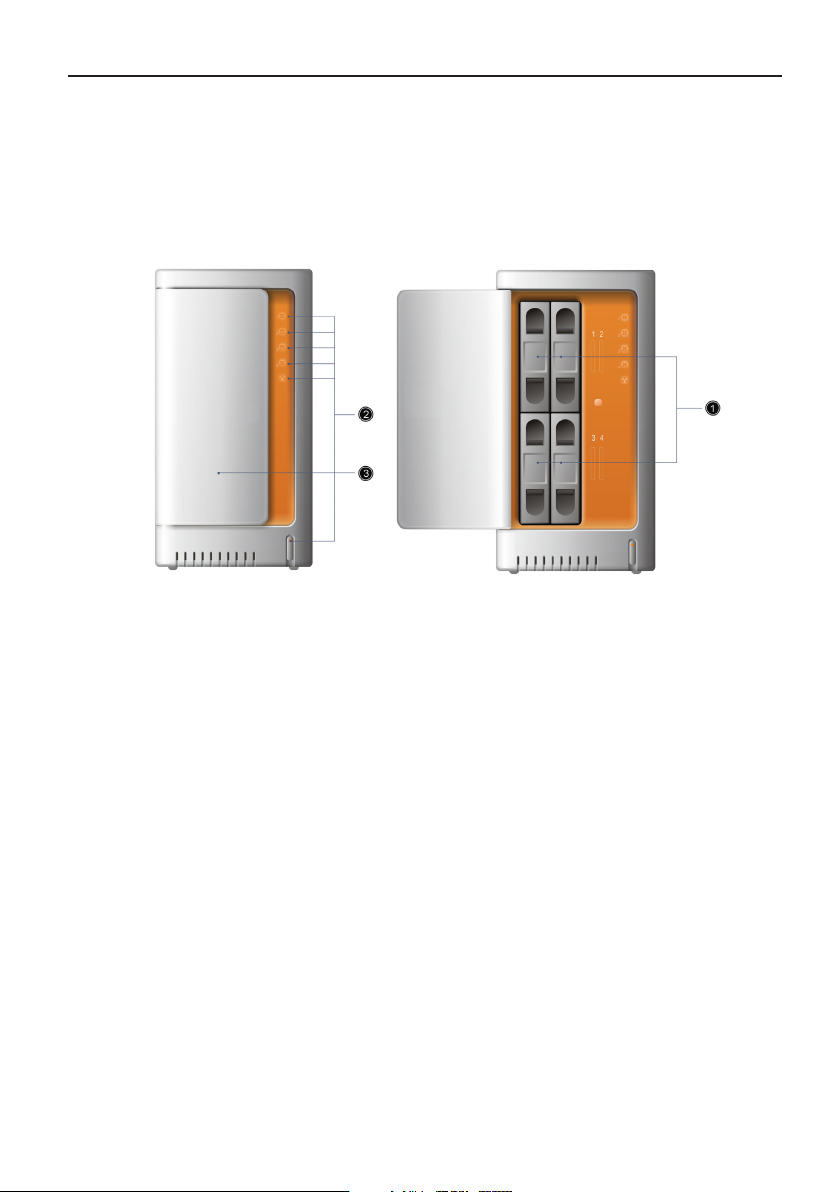
Front View
The power button and LEDs are located on the front panel.
Figure 1. Front View
(1) Power Button
(2) LEDs
(3) Front Panel
(4) HDD Trays (1-4)
Page 14
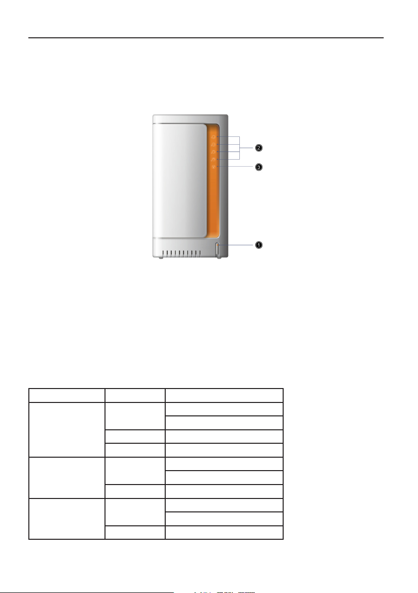
Button and LED Information
The WHS system allows easy access to the hard disk drives (HDDs). The WHS system is
equipped with status LED indicators and a power button located on the front panel.
Figure 2. Button and LEDs on the Front Panel
(1) Power Button with System LED
(2) HDD 1-4 Status LEDs
(3) Network Status LED
The detailed LED information is shown below:
Table 2. Front View LEDs
Type of LED Color Status
HDD Status LEDs Green On: Mounted
Blinking: Disk Unknown
Orange On: Failure
Off No HDD is detected
NIC LED Green On: Connected
Blinking: Active
Off Disconnected
Power Button/LED Green On: System Booted
Blinking: System Booting
Off System Shut Down
13Belinea o.center
Page 15
14 Introduction
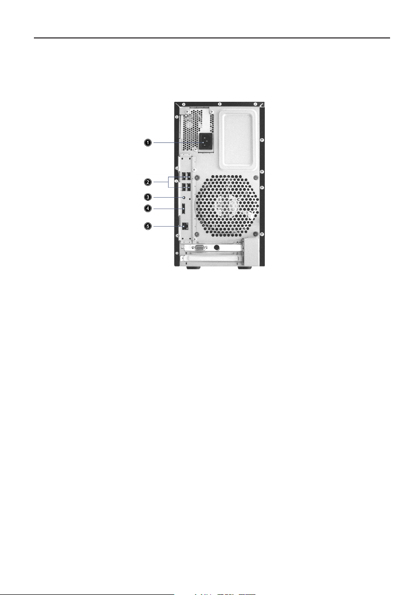
Back View
The WHS system includes the following connectors:
Figure 3. Back View
(1) AC Power Connector
(2) Rear Dual USB Ports(x2)
(3) System Recovery Button
(4) e-SATA Connector
(5) Network Connector (RJ45)
Page 16
Specifications
Table 3. Specifications
Dimensions Height: 323 mm
Width: 165 mm
Length: 283 mm (dimensions without bezel)
Weight Min-weight: 6.795 kg
Max-weight: 9.690 kg
Temperature Operating System: 0 °C to 40 °C
Non-operating System: -20 °C to +60 °C
Humidity Operating System: 20% to 85%
Non-operating System: 20% to 95%
Power Rated Input Voltage: 200 Vac to 240 Vac
Rated Input Frequency: 50 Hz
Rated Input Current: 3 A at 230 Vac
Rated Max Output Power: 250 W
15Belinea o.center
Page 17

16
Page 18

Hardware Setup
The following items are required for the Windows Home Server:
• A local area network, linked by a Router, Hub or Switch
• A client PC connected to the LAN with Windows 2000/XP/Vista Operating System
Connecting and Starting the Windows Home Server
1. Plug in the power cord.
2. Connect to the LAN via the Ethernet cable.
3. Press the power button.
Figure 4. Plugging-in power cord
17Belinea o.center
Page 19

Figure 5. Connecting to the LAN
Figure 6. Pressing the Power Button
Press the power button, and the System LED will become green and start blinking.
When the System LED stops blinking and remains solid green, the WHS system is loaded
successfully.
18 Hardware Setup
Page 20

Software Setup
Installing the Windows Home Server Connector
The Windows Home Server (WHS) operating system helps you centralize and connect
your digital assets. WHS enables you to share, store, access and automatically protect
your photos, music, videos and files of the devices connected in your home network. The
WHS Console, which is stalled on your client computers, allows you to manage the WHS
system.
Two new tools for the Microsoft WHS Console are the iWHS Control Center and the iWHS
Media Genie. The Control Center provides more data of the devices connected in your home
network. The Media Genie provides you greater control over your digital media files.
(iWHS software optional available on “http://www.maxdata.com/” >> “Downloadservice”
>> “Belinea” >> “Belinea Server”.)
To install the Windows Home Server Connector and iWHS software, please follow the
steps below.
1. Insert the CD into the first client PC in your network.
2. At the Start Panel (Figure 7), click WHS Connector, and refer to the “Microsoft
Windows Home Server Getting Started Guide” for instructions on how to install the
Windows Home Server Connector.
Figure 7. iWHS Installation Start Panel
19Belinea o.center
Page 21

20 Software Setup
3. Install the iWHS toolkit:
a) Click iWHS Toolkit for WHS on the installation Start Panel. The iWHS Control
Center and the Media Genie will be installed as Add-ins to the WHS Console.
b) Logon to the Windows Home Server Console, and click Settings on the console.
c) Click Add-ins On Windows Home Server Settings.
d) Click the Available tab. iWHS Control Center, iWHS Media Genie and iWHS Status
Daemon will be shown (Figure 8).
Figure 8. Adding the iWHS Control Center and Media Genie
e) Click Install to install the Add-in.
/ Note
The Status Daemon should be installed before the installation of the Control Center.
f) If the Installation is successful, click OK. The console will be restarted.
g) iWHS Control Center and iWHS Media Genie appear on the console.
Page 22

iWHS Control Center (optional)
Figure 9. Control Center
Click the iWHS Control Center tab on the Windows Home Server Console, and Function
Buttons will appear as shown in Figure 10.
Figure 10. Tabs under iWHS Control Center
The tabs under iWHS Control Center:
• System: Review the general configuration information and operational status of the
system
• Storage: Review the general storage information about the Hard Disk Drives of the
computer.
• Devices: Review the information about the Hardware Devices.
• Network Status: Review the network status.
• Processes: Review the current running processes.
• Remote Desktop: Connect to the selected computer through this interface and ac
-
cess to all of the applications, files, and network resources conveniently
/ Note
You must be logged on as an administrator or a member of the Administrators group to enable the Remote Desktop feature.
21Belinea o.center
Page 23

22 Software Setup
iWHS Media Genie (optional)
iWHS Media Genie is another add-in toolkit for media management. You can use the iWHS
Media Genie tab on the Windows Home Server Console to search media resources through
the network and view your media library.
Click the iWHS Media Genie tab on the Windows Home Server Console as shown in Figure 11.
Figure 11. System tabs under iWHS Media Genie
Media Library
The Media library is the location in the console that lists all of the photos, videos and music
on your personal computers. It enables you to find and play your digital media files easily.
Click the Media Library tab to display your library.
/ Note
The Photos, Videos and Music folders in Windows contain the actual files on your personal
computers; however, the Media Library contains links to those media files simply. The Media
Library lets you have greater control of organizing and using the digital media contents.
Page 24

Figure 12. Media Library under iWHS Media Genie
/ Note
Folders such as Home Server can not be deleted.
23Belinea o.center
Page 25

24 Software Setup
Media Explorer
Media Explorer detects devices connected to your network to search the media files and
display all the media files on the WHS console screen. It lets you upload the media files to the
home sever. The links to those selected media files are displayed on the Media Library.
Figure 13. Media Explorer under iWHS Media Genie
/ Note
1. The connected PC requires Windows Vista Operation System and Media Player 11 or
higher version, which enables the Home Server to detect media files on the PC.
2. If the folders are not open to share, they can not be monitored. For more information,
see Windows Help and Support.
Page 26

Monitor
When you start the Windows Home Server Console for the first time, it automatically
searches certain default folders on your computer for music, photos and videos, and then
adds those files to your Media Library. You may also change which folders the iWHS Media
Genie monitors if you store some digital media files in a location that is not already monitored automatically.
Figure 14. Monitor under iWHS Media Genie
Belinea o.center
25
Page 27

26
Page 28

Replace and Add a Hard Disk Drive (HDD)
The hard disk drive cage can support up to four 3.5” SATA HDDs. The SATA connectors
are located on the back of HDD cage and connect to the HDD when the HDD is inserted
into the cage.
The location of HDD Cage on the server chassis is shown below:
Figure 15. HDD Cage Location
HDD #1 is configured with the WHS operating system of the server as a
default. Never remove HDD #1 if you do not want to reinstall/recover the
whole operating system.
27Belinea o.center
Page 29

28 Replace and Add a Hard Disk Drive (HDD)
To Add a HDD
To add a HDD, please follow the steps below:
1. Make sure the server is turned off and disconnected from the AC power.
2. Squeeze together the recessed buttons on the front of the HDD tray.
Figure 16. Squeeze the HDD Tray Buttons
3. Slide the HDD tray out of the HDD cage
Page 30

Figure 17. Sliding out the HDD tray
4. Remove the side fasteners by pulling them outward.
Figure 18. Removing the HDD Fasteners
29Belinea o.center
Page 31

30 Replace and Add a Hard Disk Drive (HDD)
5. Position the HDD in the HDD tray.
Figure 19. Placing the HDD in the HDD Tray
6. Secure the HDD to the HDD tray with the side fasteners.
Figure 20. Securing the HDD to the HDD Tray
Page 32

7. Push the HDD assembly slowly into the server.
Figure 21. Pushing the HDD Assembly into the Server
Pay attention to the installed position of the HDD Trays to avoid wrong
installation.
31Belinea o.center
Page 33

32 Replace and Add a Hard Disk Drive (HDD)
HDD Hot-Plug
Hot Plug Feature
Your WHS supports the HDD Hot-Plug function, which enables you to remove, add-on or
swap SATA HDD while the system is powered on and under operation.
When performing hot plug operations, please wait till the operation system
starts up.
You must not remove the operating system HDD.
Adding a Hard Drive
You can add a hard drive to your server storage from the Server Storage tab of the console.
When you select a newly installed hard drive (either internal or external) and then click Add,
the Add a Hard Drive Wizard starts. The wizard helps you add a hard drive to your home-server
storage. Complete the wizard to add more space for your files to your server storage.
Hard drives are formatted before they are added to server storage. Make
sure that you back up any important files that are on the hard drive before
you add it to server storage. Formatting a hard drive deletes all files on the
hard drive.
If you add a hard drive to your server storage, you commit it to be part of
your total server-storage space. You should not disconnect the hard drive to
use it for other purposes. If you want to use the hard drive for other purposes, you should first select the hard drive and click Remove.
Page 34

To remove a HDD
You must first remove a hard drive from your server storage on the Server Storage tab of
the console.
From the Server Storage tab in the Windows Home Server Console, right-click on the hard
driver you want to remove. The Remove a Hard Drive Wizard starts. It first determines if
you have enough remaining server storage for your files, folders, and backups and enough
remaining server storage to continue Folder Duplication. If the remaining server storage is
sufficient, the wizard attempts to move the files, folders, and backups from the hard drive
to the remaining server storage.
The wizard first examines the hard drive and the remaining server storage. If you have enough
remaining server storage, you can continue and the wizard moves the folders and files from
the hard drive to the remaining server storage. You can then disconnect the hard drive.
If you do not have enough remaining server storage, you can lose Folder Duplication,
permanently lose files, permanently lose all of your personal computer backups, or any
combination of the three. The wizard calculates the exact consequences and shows them
to you before the hard drive is actually removed from server storage.
To avoid these consequences, do the following:
1. Cancel the wizard.
2. Add another hard drive to server storage by using the Add a Hard Drive Wizard. The
additional hard drive provides enough server storage for the Remove a Hard Drive
Wizard to move the files.
3. Choose the hard drive that you want to remove, and then run the Remove a Hard
Drive Wizard again to move the files and folders.
4. Disconnect the hard drive.
You will lose all files on a hard drive if you physically disconnected it from
your home server without running the Remove a Hard Drive Wizard and
you can no longer find the hard drive to connect it again. To protect your
files you must run the Remove a Hard Drive Wizard.
Repair HDD
If one or more volumes on the hard drive are corrupt, the hard drive needs to be repaired.
You can repair a hard drive from the Server Storage tab of the console.
Select the hard drive, and then click Repair.
If you select an unhealthy hard drive and then click Repair, the Repair a Hard Drive Wizard
starts. It attempts to fix errors by scanning the hard drive using the CHKDSK utility to verify
the integrity of the hard drive.
/ Note
CHKDSK is a Windows program than can detect and repair errors on a hard drive.
It will correct disk errors, if possible, and rebuild shared folders duplication, if necessary.
Belinea o.center
33
Page 35

34
Page 36

Troubleshooting
LED Indicators
On the front panel of WHS system, you can find the LED indicators:
• 4 x HDD Status LED Indicator
• 1 x Network LED Indicator
• 1 x System LED Indicator
For LED information, refer to Table 2 on page 13.
HDD Status LED Indicators
There are 4 HDD slots and 4 corresponding LED indicators:
When the color is Green, the HDD is in use and healthy.
When the color is Orange, the HDD is in use but corrupt.
When the light is off, a HDD is not detected.
Network LED Indicator
The LED indicator for network status uses a single Green LED to indicate the network is
connected or not:
When the light is off, the network is not connected or working.
When the light is on, network is connected.
When it is blinking, the network is busy receiving/sending messages.
System LED Indicator
The LED indicator for system status uses a single Green LED to indicate the system is
running or not:
When the light is off, the system is shut down.
When the light is on, the system has booted.
When it is blinking, the system is booting.
35Belinea o.center
Page 37

36 Troubleshooting
How to Recover a WHS System via Recovery Disk
If your WHS experiences a serious problem, you may need to run the recovery application
to restore your Windows Home Server system.
Before you start the recovery process, insert the Recovery Disk and shutdown your WHS
system or detach the powercord for at least 10 seconds. Connect the USB Stick for recovery
to one of the USB Ports on the back of the WHS system.
1. To recover your WHS system, you will need to use the recovery button.There are two
ways to start the recovery process:
a) Simultaneously press Power button and Recovery button.
b) Press the Recovery button for more than 5 seconds, meanwhile pressing the
Power button once.
The figure below shows the location of the recovery button.
Figure 22. Location of recovery button
Page 38

2. Run the recovery application on your client PC and click the Find home server button.
Figure 23. Recovery window to find and recover the WHS
3. Select a server and click the Recover home server button.
Figure 24. Recovering Windows Home Server
4. Restart your Windows Home Server.
5. Click Install connector software to install Windows Home Server connector.
37Belinea o.center
Page 39

Figure 25. Installing WHS Connector
Quitting the recovery may do harm to your WHS HDDs. The application will
give you a warning message and disable you to close the application.
For more information about how to configure WHS when installing WHS console, refer to
“Software Setup” on page 19.
38 Troubleshooting
Page 40

Expansion Cards
The motherboard provides one PCI, one PCI-Express 16X and two DIMM memory slots.
PCI and PCI-E 16X expansion Cards
The PCI and PCI-E 16X expansion cards share many similarities in removal and installation
procedures. The following is an example of PCI-E expansion card.
The location of the expansion card is shown below:
Figure 26. Expansion Card Location
39Belinea o.center
Page 41

40 Expansion Cards
To install a PCI or PCI-Express 16X expansion card
For installing the expansion cards, please follow the steps below:
1. Make sure the server is turned off and not connected to the AC power.
2. Remove the side cover:
a) Remove the two screws on the back of the side cover.
b) Slide the cover horizontally to the back and remove the cover from the chassis as
shown in the picture below.
Figure 27. Releasing the Side Cover
3. Remove the front panel:
a) Press the two latches of the front panel outwards against the HDD cage.
Figure 28. Releasing the Front Panel from the Server Chassis
Page 42

b) Remove the front panel from the server chassis.
Figure 29. Removing the Front Panel from the Chassis
When removing the front panel, you’ll see a cable that connects the front
panel with the motherboard located in the WHS box. Don’t stretch the cable
too hard, as it will never bother your operation.
c) Pull out the cable connections of the front panel.
Figure 30. Pulling out the Cable Connections of the Front Panel
You also can pull out the connector after removing the HDD cage as described in steps 4 and 5.
41Belinea o.center
Page 43

42 Expansion Cards
4. Remove the HDD Cage:
a) Loosen three screws on the front of the server chassis and two screws on the
back of the server chassis.
Figure 31. Loosening the HDD Cage
b) Slide the HDD Cage horizontally forwards, and pull the HDD Cage up vertically.
Then put it aside carefully
Figure 32. Pulling out the HDD cage
Don’t stretch the cable that connects the HDD cage with the motherboard
located in the WHS box too hard, as it will never bother your operation.
Page 44

5. Pull out the cable connections of HDDs.
Figure 33. Pulling out the Cable Connections of HDDs
When installing the HDD cage back, make sure to use the correct order to
ensure correct operation of the LEDs on the front panel.
Figure 34. Connecting SATA cable
43Belinea o.center
Page 45

44 Expansion Cards
6. Pull out the slot cover
Figure 35. Pulling out the slot cover
9. Insert the expansion card vertically
Figure 36. Inserting the Expansion Card
Please make sure the expansion card is plugged into a compatible slot. Do
not try to plug a PCI-X expansion card into a PCI slot, which may damage
the PCI-X adapter.
To remove a PCI or a PCI-E 16X expansion card
Reverse the steps above to remove an expansion card.
Page 46

DIMM
To install a DIMM
Figure 37. DIMM Location
In order to install a DIMM, please follow the steps below:
1-6. Follow the corresponding steps for installing a PCI or PCI-E 16X expansion card.
7. Release the clips on both sides of the card slot.
Belinea o.center
Figure 38. Releasing the clips
45
Page 47

8. Insert the DIMM.
Figure 39. Insert the DIMM
9. Fasten the clips on both sides of the card slot.
Figure 40. Fasten the clips
To remove a DIMM
Reverse the steps above to remove a DIMM.
46 Expansion Cards
Page 48

Regulation Information
Returning the Device/Battery
We accept the return of all our products after they have been used if the
condition corresponds to standard proper usage. Returned devices are either slated for further use or dismantled and recycled in an environmentally
sound manner. The return is handled through your dealer.
Rechargeable and disposable batteries containing heavy metals should not be thrown in
with household waste. They are accepted free of charge by manufacturers, dealers or their
representatives for recycling or disposal.
The outside packaging and all inner parts of the box can be disposed of as waste paper.
Disposal of waste equipment by users in private households in the European Union
This symbol on the product or on its packaging indicates that this
product must not be disposed of with your other household waste.
Instead, it is your responsibility to dispose of your waste equipment
by handing it over to a designated collection point for the recycling of
waste electrical and electronic equipment. The separate collection and
recycling of your waste equipment at the time of disposal will help to
conserve natural resources and ensure that it is recycled in a manner
that protects human health and the environment. For more information about where you can drop off your waste equipment for recycling,
please contact your local city office, your household waste disposal
service, or the shop where you purchased the product.
47Belinea o.center
Page 49

48 Regulation Information
Intended Application Uses
/ Note
This product was evaluated as Information Technology Equipment (ITE), which may be
installed in offices, schools, computer rooms, and similar commercial type locations. The
suitability of this product for other product categories and environments (such as medical,
industrial, residential, alarm systems, and test equipment), other than an ITE application,
may require further evaluation.
Site Selection
/ Note
The system is designed to operate in a household environment. Choose a site that is:
• Clean, dry, and free of airborne particles (other than normal room dust).
• Enough interface kept between the equipment and other objects plane, such as wall.
• Avoid setting the equipment on soft surface, such as blanket.
• The bottom ventilation hatch shall be kept unblocked.
• Well-ventilated and away from sources of heat including direct sunlight and radiators.
• Away from sources of vibration or physical shock.
• Isolated from strong electromagnetic fields produced by electrical devices.
• In regions that are susceptible to electrical storms, we recommend you plug your sys
tem into a surge suppresser and disconnect telecommunication lines to your modem
during an electrical storm.
• Provided with a properly grounded wall outlet.
• Provided with sufficient space to access the power supply cord(s), because they
serve as the product's main power.
• Mechanical Loading – Mounting of the equipment in the rack should be such that a
hazardous condition is not achieved due to uneven mechanical loading.
-
Tools Required
A cross screwdriver or a flat screwdriver is needed to install or remove the components
in the server.
Page 50

Regulatory Information
Regulatory Compliance Identification Numbers
For the purpose of regulatory compliance certifications and identification, this server is
assigned a serial number. This server serial number can be found on the product label,
along with the required approval markings and information. When requesting certification
information for this product, always refer to this serial number. This serial number should
not be confused with the marketing name or model number.
Product Regulatory Compliance
Product Safety Compliance
This server complies with the following safety requirements:
Table 4. Product Safety Requirements
IEC 60950-1 Safety of Information Technology Equipment
EN 60950-1 Safety of Information Technology Equipment Including Electrical Business
UL 60950-1 Safety of Information Technology Equipment
UL 94 Tests for Flammability of Plastic Materials for Parts in Devices & Appliances
Equipment, European Committee for Electrotechnical Standardization
(CENELEC)
Worldwide Safety approvals can be supplied according to the requirements from Marketing
or Customer.
Product EMC Compliance
This product has been tested and verified to comply with the following electromagnetic
compatibility (EMC) regulations.
Communications Commission Notice
Part 15 of the Federal Communications Commission (FCC) Rules and Regulations has established Radio Frequency (RF) emission limits to provide an interference-free radio frequency
spectrum. Many electronic devices, including computers, generate RF energy incidental to
their intended function and are, therefore, covered by these rules. These rules place computers and related peripheral devices into two classes, A and B, depending upon their intended
installation. Class A devices are those that may reasonably be expected to be installed in
a business or commercial environment. Class B devices are those that may reasonably be
expected to be installed in a residential environment (for example, personal computers). The
FCC requires devices in both classes to bear a label indicating the interference potential of
the device, as well as additional operating instructions for the user.
The rating label on the device shows which class (A or B) the equipment falls into. Class A
devices do not have an FCC logo or FCC ID on the label. Class B devices have an FCC logo
or FCC ID on the label. Once the class of the device is determined, refer to the following
corresponding statement.
49Belinea o.center
Page 51

50 Regulation Information
Class B Equipment
This equipment has been tested and found to comply with the limits for a Class B digital
device in accordance with the specifications in part 15 of the FCC rules. These specifications are designed to provide reasonable protection against such interference in a residential
installation. However, there is no guarantee that interference will not occur in a particular
installation. This equipment generates, uses, and can radiate radio frequency energy and, if
not installed and used in accordance with the instructions, may cause harmful interference
to radio communications.
If your computer system does cause interference to radio or television reception, try to
correct the interference by using one or more of the following measures:
• Reorient or relocate the receiving antenna
• Increase the separation between the equipment and the receiver
• Connect the equipment to a power outlet on a circuit different from that to which the
receiver is connected
• Consult the dealer or an experienced radio/TV technician for help
European Union Notice
Products with the CE Marking comply with both the EMC Directive (89/336/EEC) and the LowVoltage Directive (73/23/EEC) issued by the Commission of the European Community.
Compliance with these directives implies conformity to the following European Norms (in
brackets are the equivalent international standards):
Table 5. European Union EMC Requirements
EN55022 (CISPR 22) Electromagnetic Interference
EN55024 (IEC61000-4-2,3,4,5,6,8,11) Electromagnetic Immunity
EN61000-3-2 (IEC61000-3-2) Power Line Harmonics
EN61000-3-3 (IEC61000-3-3) Power Line Flicker
Page 52

Power Cords
The power cord set included in the server meets the requirements for use in the country
where the server was purchased. If this server is to be used in another country, purchase
a power cord that is approved for use in that country.
The power cord must be rated for the product and for the voltage and current marked on
the product's electrical ratings label. The voltage and current rating of the cord should be
greater than the voltage and current rating marked on the product. In addition, the crosssectional area of the wires must be a minimum of 1.00 mm² or 18 AWG, and the length of
the cords must be between 1.8 m (6 feet) and 3.6 m (12 feet). If you have questions about
the type of power cord to use, contact an authorized service provider.
Route power cords so that they will not be walked on or pinched by items
placed upon or against them. Pay particular attention to the plug, electrical
outlet, and the point where the cords exit from the product.
51Belinea o.center
Page 53

 Loading...