

Page 1
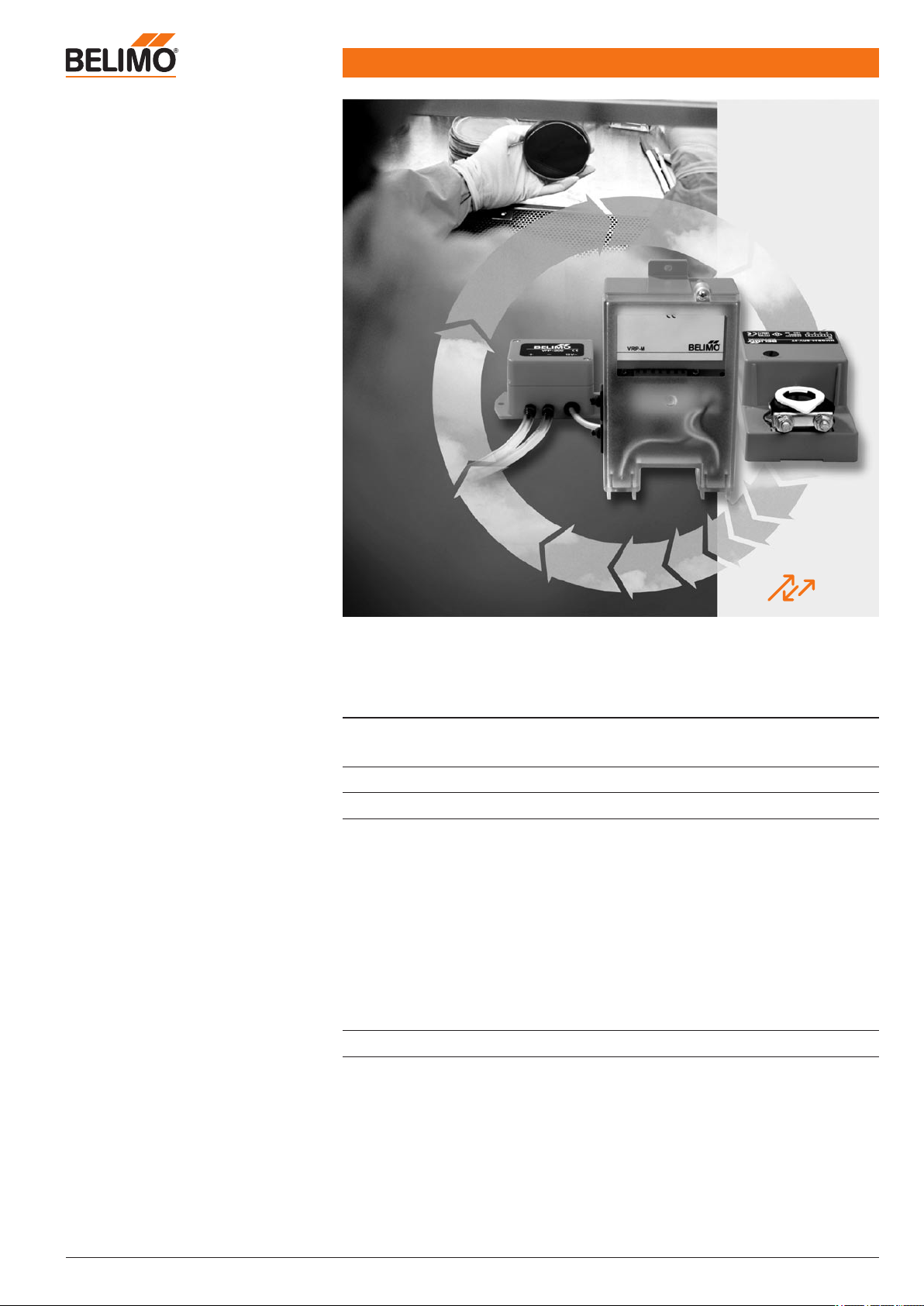
Product information VRP-M VAV system
www.belimo.eu Product information S4-VRP-M VAV • en • v2.0 • 11.2006 • Subject to changes 1 / 28
Table of Contents
Overview of the system
2
System description
3
Technical data sheets
VRP-M adaptive, digital PID VAV controller
Application
Functions
System configuration
Operating data settings (with VRP-M-Tool)
Connection of the VRP-M-Tool
Bus operation
VFP-.. static differential pressure sensors for neutral to slightly aggressive gases
Fast-running damper actuator for VRP-M system solution NMQB24-SRV-ST
Damper actuator for VRP-M system solution NM24A-V-ST
7
8
9
12
13
15
16
19
21
23
Dimensions
25
Adaptive VAV control system
for sensitive working areas
MP
BUS
®
TECHNOLOGY BY BELIMO
Page 2
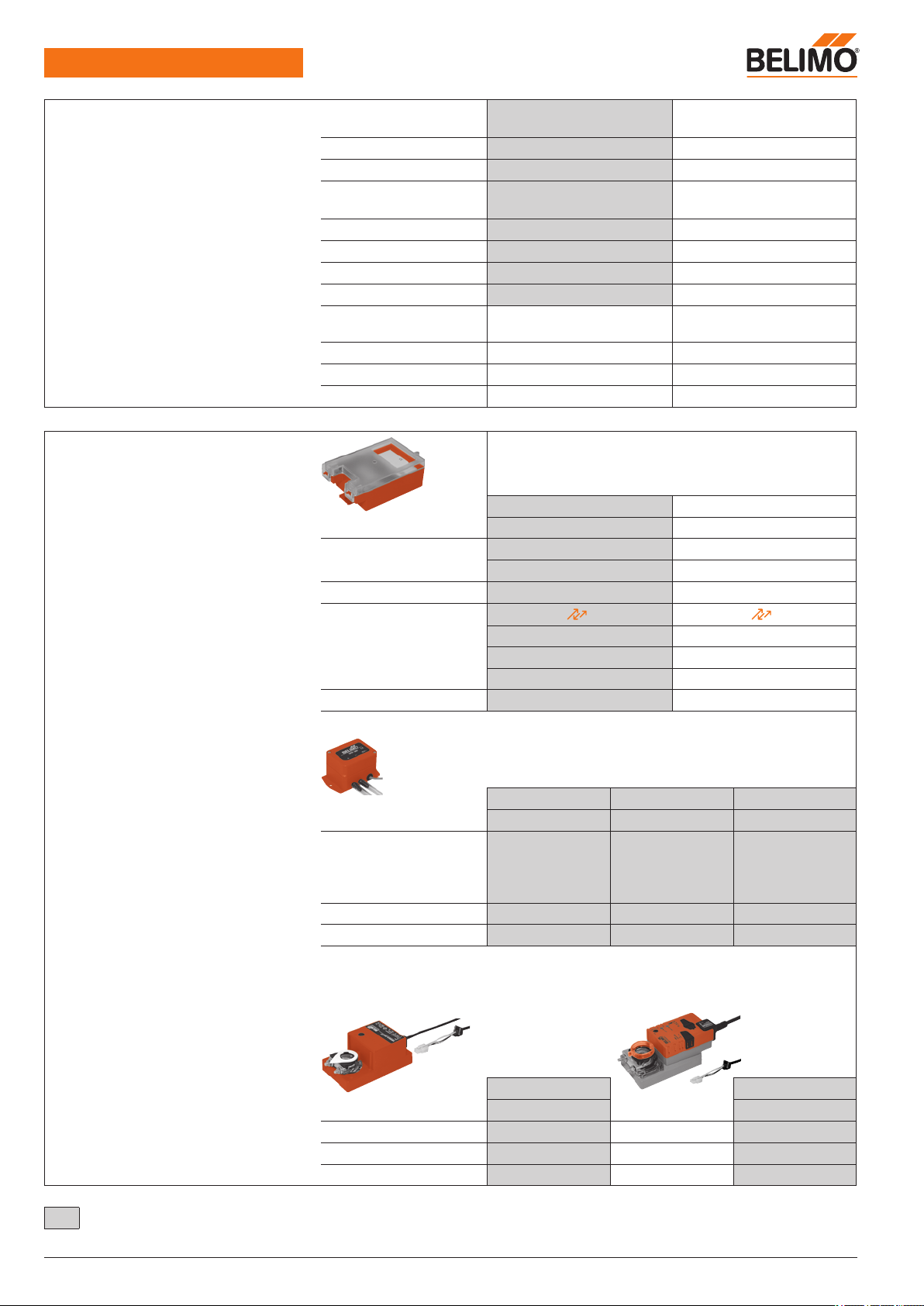
VRP-M VAV
Overview of the system
2 / 28 Product information S4-VRP-M VAV • en • v2.0 • 11.2006 • Subject to changes www.belimo.eu
Pressure sensors for
static differential pressure measurement
VFP-100 VFP-300 VFP-600
Pressure range 0 ... 100 Pa 0 ... 300 Pa 0 ... 600 Pa
Medium
– Slightly dusty air
– Very dusty air
– Corrosive gases
●
●
*
●
●
*
●
●
*
Power supply From VRP-M From VRP-M From VRP-M
VRP-M connection Ready to connect Ready to connect Ready to connect
* For a list of sensor materials that come into contact with the medium,
see «Technical data» for the VFP-.., page 19
Damper actuators
NMQB24-SRV-ST NM24A-V-ST
Torque 4 Nm 10 Nm
Speed < 5 s 110 ... 150 s
Power supply From VRP-M From VRP-M
VRP-M connection Ready to connect Ready to connect
VAV functions
Application
Volumenstrom
VAV / CAV
Pressure
STP
VAV:
min
...
max
●
CAV:
min
/
mid
/
max
●
Override functions:
Open – closed
●
Extraction systems ●
Laboratory exhaust systems ●
Bus integration ● ●
Fan optimisation ●
Modulating pressure:
P
min
… P
max
●
Stepped pressure: P
min
/ P
max
●
Override functions OPEN / CLOSE
●
Motor stop function ●
System components
VRP-M control solution
VRP-M
VAV / CAV STP
Power supply AC/DC 24 V AC/DC 24 V
Modulating control 0 ... 10 / 2 ... 10 V 0 ... 10 / 2 ... 10 V
0 ... 20 / 4 ... 20 mA 0 ... 20 / 4 ... 20 mA
Stepped control Contacts, switches Contacts, switches
Bus function
MP
BUS
®
TECHNOLOGY BY BELIMO
MP
BUS
®
TECHNOLOGY BY BELIMO
– Optimiser COU24-A-MP ●
– LONW
ORKS
®
integration
● ●
– EIB/Konnex integration
● ●
Settings, diagnostics VRP-M-Tool VRP-M-Tool
Page 3
www.belimo.eu
Product information S4-VRP-M VAV • en • v2.0 • 11.2006 • Subject to changes
3 / 28
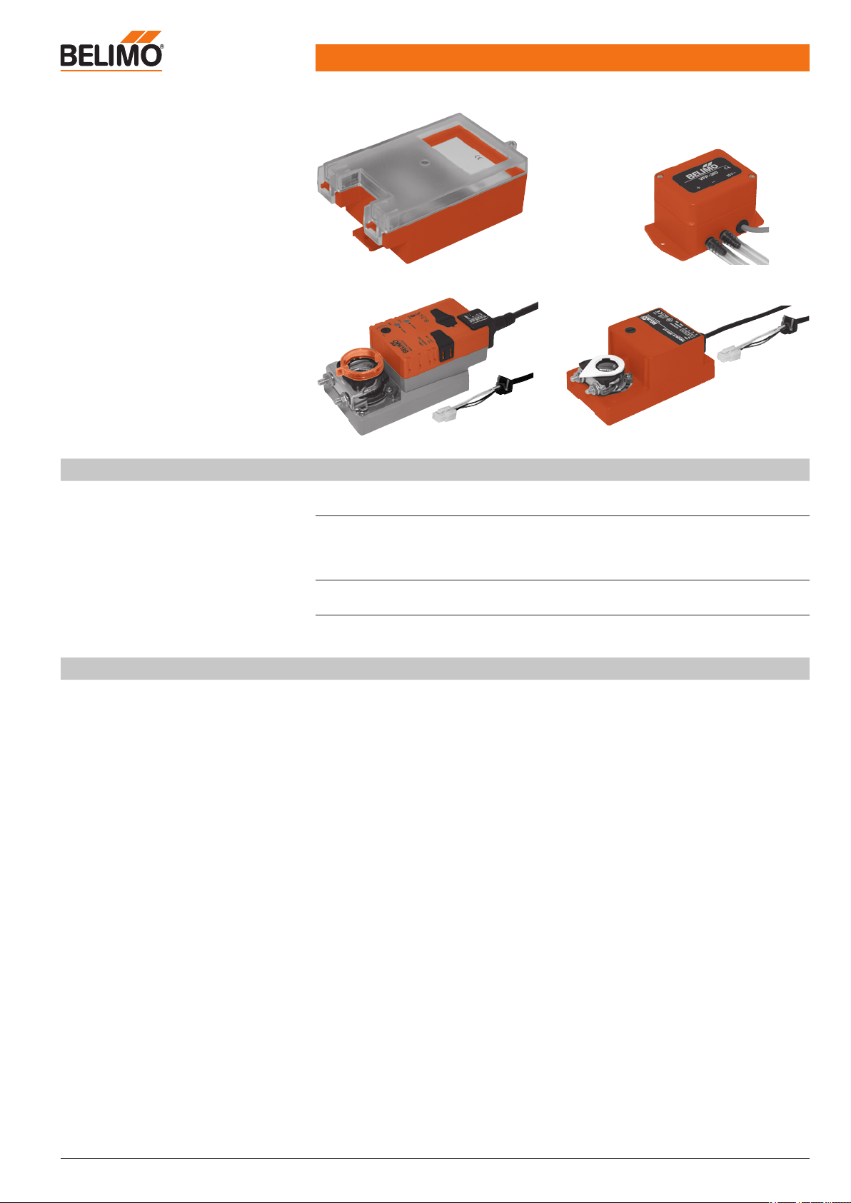
System components
Controller
VRP-M adaptive, digital PID VAV controller
for every application
Pages 7 ... 18
Sensor
Pressure sensors for static differential pressure measurement
– VFP-100 with 0 ... 100 Pa measuring range
– VFP-300 with 0 ... 300 Pa measuring range
– VFP-600 with 0 ... 600 Pa measuring range
Pages 19 ... 20
Actuator
– NM24A-V-ST damper actuator for standard applications
1)
– NMQB24-SRV-ST damper actuator for fast-running applications
1)
Pages 21 ... 24
1)
Please contact your Belimo representative for other actuator solutions, e.g. spring return.
Brief description
Application
This ready-to-connect system solution is an efficient control system for pressure-independent,
standard and fast-running air volume applications.
Field of application
The system can be used for controlled extraction of contaminated or slightly aggressive air 1) in closed
rooms:
– Exhaust air systems for laboratory workplaces *
– Laboratories in chemical and pharmaceutical plants *
– Hospital buildings *
In combination with the NMQB24-SRV-ST fast-running actuator, this system is particularly suited to
laboratory applications *:
– Digesters *
– Extraction of contaminated air *
* Air compatibility verification essential (see «Technical data» for the VFP-... sensors, page 19).
Function
The pressure differential at the static pressure sensor is converted into a volumetric flow signal with
a linear throughflow and serves as the actual value x for the adaptive PID-VAV controller. The volumetric flow signal (0 ... 100%
nom
) can be picked off at the VRP-M, controller connection U5, as a
0 ... 10 / 2 ... 10 V signal.
The actual value x is compared with the setpoint w set on the VAV controller and the connected
damper actuator is controlled according to the resulting system deviation. The VRP-M controller can
be controlled according to its function as a CAV constant controller (
min
/
max
) or a VAV controller via
the reference value input w with a modulating 0 ... 10/2 ... 10 V signal in the range from
min
...
max
.
Control inputs with OPEN/CLOSE/
mid
functions are available for special applications.
The VRP-M can be integrated into an MP system via the MP-Bus connection.
Ready-to-connect system solution for
• Pressure-independent VAV and CAV
systems, e.g. in laboratories
• Fast-running VAV and CAV applications, e.g. in digesters or generally for
extracting contaminated or slightly aggressive air in closed rooms
Control:
DC 2 ... 10 V / 0 ... 10 V or bus
Integration into
• DDC controller with MP interface
• EIB Konnex systems
• LONWORKS® systems
Settings and diagnostics
with VRP-M-Tool
System description VRP-M VAV system
VRP-M
VFP-..
NMQB24-SRV-STNM24A-V-ST
Page 4

VRP-M VAV
Ready-to-connect system solution
4 / 28 Product information S4-VRP-M VAV • en • v2.0 • 11.2006 • Subject to changes www.belimo.eu
Safety notes
!
• The VRP-M system solution is not allowed be used for applications outside the specified field
of application, especially in aircraft or in any other airborne means of transport.
• Only components explicitly approved for this purpose by Belimo are allowed to be used for
the VRP-M system solution.
• The equipment configuration and settings form part of the unit manufacturer‘s system solution (OEM) and are not allowed to be modified without prior authorisation. All changes are
liable to disrupt operation and cause damage to the system or injury to persons!
• Attention must be paid to the following during the planning phase and before the VRP-M
system solution is operated:
– The compatibility of the VFP-.. sensor with the medium to be controlled must be verified,
– The specifications supplied by the VAV unit manufacturer (design, installation site) must
be consulted,
– All local regulations must be observed.
• Applications with fast-running actuator NMQB24-SRV-ST: The actuator moves into the
«CLOSED» position (left or right end stop, depending on the position of the direction of rotation switch) when the supply voltage is switched on, in the event of a power failure >5 s or if
the pushbutton is actuated again. It then moves into the position required by the system. The
VRP-M control function is inoperative during this procedure.
• If the VRP solution is operated in a bus system, the cycle times of the MP-Bus and the
higher-level system must be taken into account.
• The manufacturer of the VAV unit (OEM) is responsible for ensuring that the VRP-M-system
solution is installed and set correctly as well as for the overall precision of the VAV unit.
If replacement devices are ordered, they are configured by the OEM at the factory according
to the installed system.
The VRP-M system solution is sold exclusively via the OEM channel for this reason.
System characteristics
Control characteristics
Adaptive, digital PID VAV controller (see «System components», page 3).
Pressure measurement
Static Belimo pressure sensors (see «System components», page 3).
Damper actuators
Belimo VAV damper actuators (see «System components», page 3).
Optimally matched components
In addition to standard VAV and CAV applications, the VRP-M system solution is also suitable for
fast-running applications such as those used in laboratories. The solution comprises optimally
matched, ready-to-connect components. These are only permitted for use in the controller-sensor-actuator combinations specified by Belimo and selected by the unit manufacturer (see «System components», page 3).
VAV – variable air volume
Variable air volume applications based on a modulating reference signal, e.g. supplied by a DDC
controller, room temperature controller, EIB Konnex or LONW
ORKS
®
system.
The reference signal for the
min
...
max
working range can be set as follows:
DC 2 ... 10 V / DC 0 ... 10 V / adjustable DC range / bus operation
CAV – constant air volume
Constant air volume applications with operating steps (relays, switching contacts).
The following operating steps are available: CLOSED /
min
/
mid
/
max
/ OPEN / bus operation
Bus function
Up to eight Belimo MP devices (VRP-M / VAV-Compact / damper actuator / valve) can be connected via the MP-Bus and integrated into the following systems:
– DDC controller with integrated MP-Bus protocol
– EIB Konnex system with Belimo UK24EIB interface
– LONW
ORKS
®
system with Belimo UK24LON interface
See pages 16...18
Diagnostics tool
VRP-M-Tool, plugged either directly onto the VRP-M VAV controller or via a terminal in the control cabinet (connection 4 – PP/MP)
Version overview – VRP-M system solution
Refer to www.belimo.eu for current information about compatibility, versions and functions.
Page 5
VRP-M VAV
Ready-to-connect system solution
www.belimo.eu Product information S4-VRP-M VAV • en • v2.0 • 11.2006 • Subject to changes 5 / 28
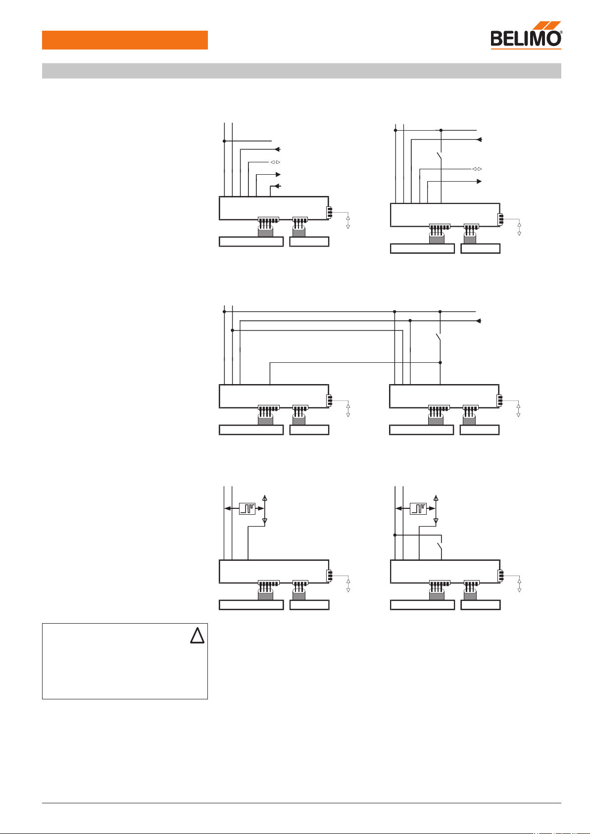
Electrical installation
Wiring diagrams: VAV operation Example 1:
With analogue reference signal
Example 2:
DC 0 ... 10 V with shut-off (CLOSED)
Conventional operation:
See pages 10 and 11 for a description of
functions such as control priority
AC 24 V
DC 24
V
~
T
+
_
T
4321 VRP-M
MPw
~
T
+
_
5 6 7
U5 z1 z2
VFP-...NM...-ST
VRP-M
Tool
4321 VRP-M
MPw
~
T
+
_
5 6 7
U5 z1 z2
VFP-...NM...-ST
VRP-M
Tool
+
DC 24
V
_
AC 24 V
DC 24
V
~
T
+
_
T
Example 3:
DC 0 ... 10 V with shut-off / parallel control
4321 VRP-M
MPw
~
T
+
_
5 6 7
U5 z1 z2
VFP-...NM...-ST
VRP-M
Tool
+
DC 24
V
_
AC 24 V
DC 24
V
~
T
+
_
4321 VRP-M
MPw
~
T
+
_
5 6 7
U5 z1 z2
VFP-...NM...-ST
VRP-M
Tool
+
DC 24
V
_
T
Example 4:
With bus control
Beispiel 5:
Typical application: MP with shut-off (CLOSED)
Bus control:
See pages 16 to 18 for a description of functions
MP
~
T
+
_
AC 24
V
DC 24
V
4321 VRP-M
MPw
~
T
+
_
5 6 7
U5 z1 z2
VFP-...NM...-ST
VRP-M
Tool
MP
~
T
+
_
AC 24
V
DC 24
V
4321 VRP-M
MPw
~
T
+
_
5 6 7
U5 z1 z2
VFP-...NM...-ST
VRP-M
Tool
Reference value input w
0 ... 10 / 2 ... 10 / adjustable
PP/MP communication
Volume flow actual value U5
0 ... 10 / 2 ... 10 / adjustable
Control input z
PP/MP communication
Volume flow actual value U5
0 ... 10 / 2 ... 10 / adjustable
CLOSED (shut-off)
ZU (Absperrung)
CLOSED (shut-off)
Reference value input w
0 ... 10
Note
– Supply via safety isolation transformer!
– We recommend routing connections 1, 2
(AC/DC 24 V) and 4 (MP signal) to accessible
terminals (floor distributor, control cabinet, etc.),
in order to simplify access with the VRP-M-Tool
for diagnostic and service work.
!
Page 6
VRP-M VAV
Ready-to-connect system solution
6 / 28 Product information S4-VRP-M VAV • en • v2.0 • 11.2006 • Subject to changes www.belimo.eu
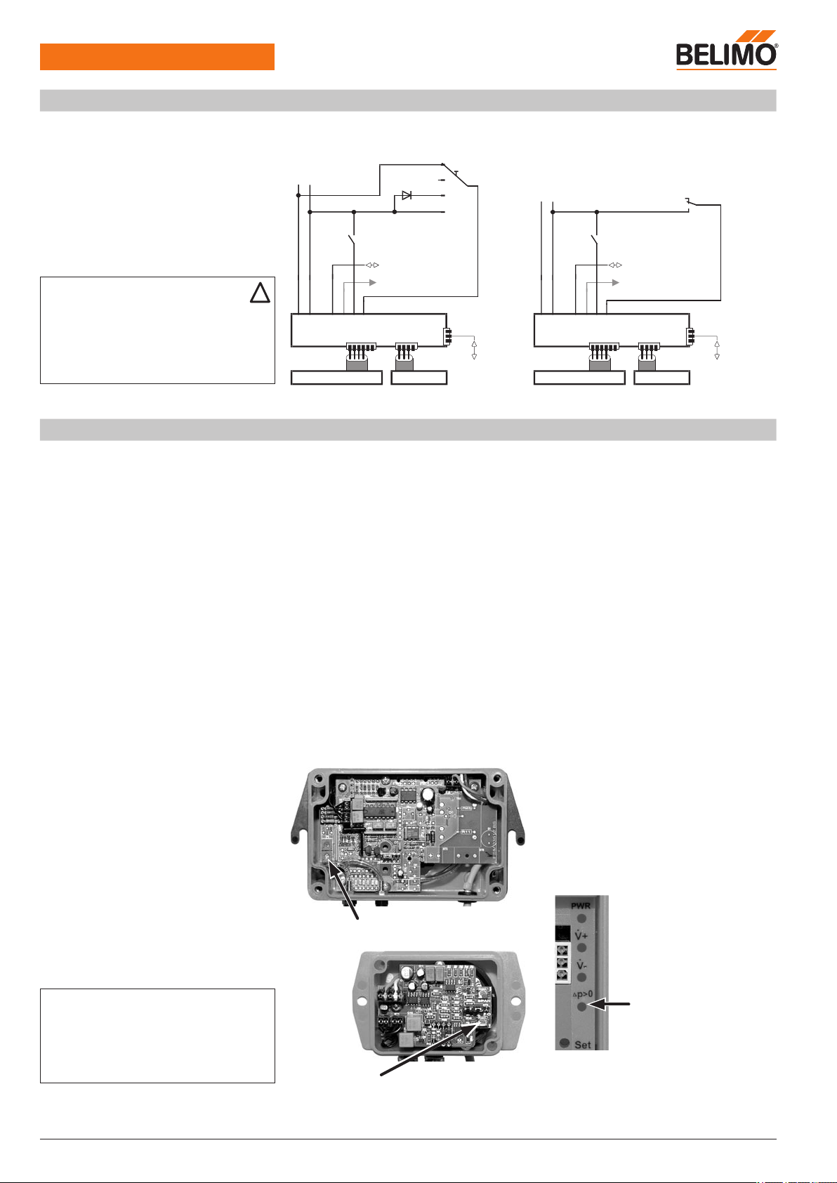
Commissioning
Prerequisites
– The VAV / CAV unit must be mounted
– The VRP-M system solution must have been set and calibrated for the VAV / CAV unit by the
unit manufacturer
– The electrical connection must have been made and checked
– The 24 V supply and control must be ready for operation
– The system fan must be in operation
Procedure
– Check the electrical connection
– Check the zero offset of the pressure sensor
– Check the damper mobility
– Check the supply pressure (the system fan must be in operation and calibrated)
– Check the
min
/
max
settings and correct them if necessary
– Check the control signal setting and adjust it if necessary
Angle of rotation adaptation
The angle of rotation must be adapted whenever the angle of rotation limiting of the
NMQB24-SRV-ST damper actuator is adjusted.
Procedure:
– Switch on the 24 V supply
– Press the manual override pushbutton twice
The actuator moves into the CLOSED...OPEN...setpoint position
VFP-.. static pressure sensor
Zero offset
– Disconnect both (!) hose connections from the
sensor
– Remove the cover of the VFP-.. sensor
housing
– Turn the zero potentiometer inside the VFP‐..
until the LED in the VRP-M [p>0] lights up
– Turn the zero potentiometer back until the LED
goes out again
Zero potentiometer VFP-100
Note
Fast-running damper actuator NMQB24-SRV-ST
A synchronisation is performed after the power sup
-
ply is switched on or after the manual disengage
ment is actuated; this means the actuator moves to
CLOSED and returns to its nominal position.
Zero potentiometer VFP-300
VFP-600
Electrical installation
(Continued)
Wiring diagrams: CAV operation Example 1: Example 2:
min
–
max
– OPEN
See pages 10 and 11 for a description of function
Note
– Supply via safety isolation transformer!
– We recommend routing connections 1, 2
(AC/DC 24 V), 4 (MP signal) and 5 (U5 signal)
to accessible terminals (floor distributor, control
cabinet, etc.), in order to simplify access with the
VRP-M-Tool for diagnostic and service work.
!
4
3
2
1 VRP-M
MPw
~
T
+
_
5
6
7
U5 z1 z2
VFP-...NM...-ST
VRP-M
Tool
+
DC 24
V
_
AC 24 V
DC 24
V
~
T
+
_
4
3
2
1 VRP-M
MPw
~
T
+
_
5
6
7
U5 z1 z2
VFP-...NM...-ST
VRP-M
Tool
+
DC 24
V
_
AC 24 V
DC 24
V
~
T
+
_
* Function not available with DC 24 V supply.
PP/MP communication
Volume flow actual value U5
0 ... 10 / 2 ... 10 / adjustable
CLOSED
OPEN
min
max
OPEN (damper open)
min
max
PP/MP communication
Volume flow actual value U5
0 ... 10 / 2 ... 10 / adjustable
mid
*
LED ∆p>0
VRP-M
Page 7
Technical data sheet VRP-M VAV controller
www.belimo.eu Product information S4-VRP-M VAV • en • v2.0 • 11.2006 • Subject to changes 7 / 28
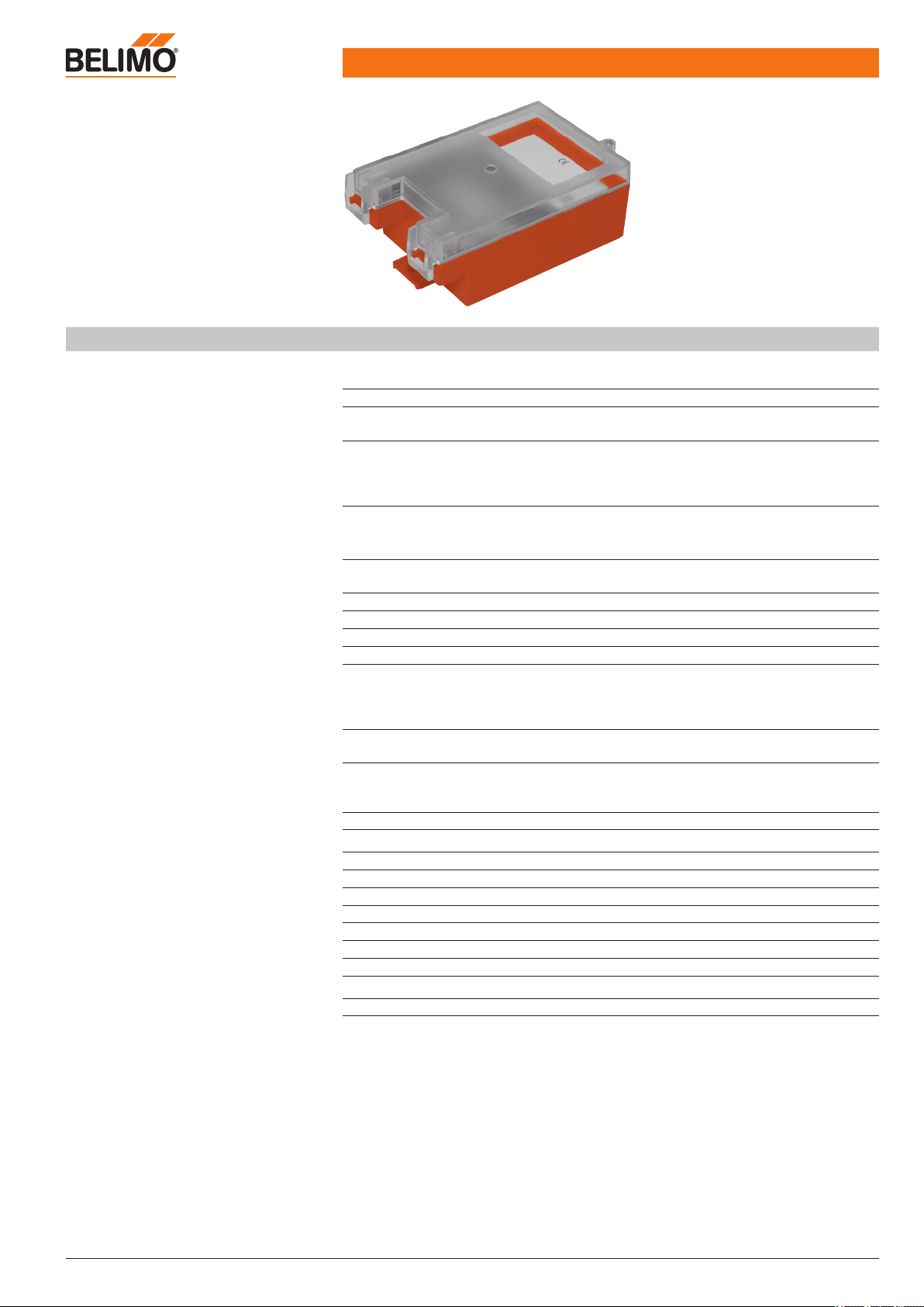
Adaptive digital PID VAV controller
for VRP-M system solutions
• For pressure-independent VAV and
CAV systems
• Control:
DC 0 ... 10 V / 2 ... 10 V or bus
• Diagnostics socket for VRP-M-Tool
Technical data
Electrical data
Nominal voltage AC 24 V, 50/60 Hz
DC 24 V
Power supply range AC ±20% / DC ±10%
Power consumption In operation
For wire sizing
1.1 W (incl. VFP-.. sensor, without actuator)
2.6 VA (incl. VFP-.. sensor, without actuator)
Connection Actuator
Pressure sensor
Terminals 1 ... 7
VRP-M-Tool
Plug, 6-pin
Plug, 4-pin
Screw terminals, 7-pin, 0.5 mm2 ... 1.5 mm
2
Plug, 3-pin
Functional data
VAV reference signal w (terminal 3)
Range:
min
...
max
Input impedance >200 kΩ
– DC 0 ... 10 / 2 ... 10 V or
– 0 ... 20 / 4 ... 20 mA (with 500 Ω resistance)
Volumetric flow actual value U5 (terminal 5)
Range 0 ... 100%
nom
DC 0 ... 10 / 2 ... 10 V, max. 5 mA
OPEN operating step – z1 (terminal 6) OPEN, input impedance >300 kΩ
CAV operating steps z2 (terminal 7) CLOSED /
min
/
mid
/
max
, contact current <1 mA
Control characteristics PID, adaptive
Control tolerance ±5% of
nom
Ranges
nom
max
min
*
mid
(intermediate position) **
Nominal volumetric flow (manufacturer-specific)
30 ... 100% of
nom
0 ... 100% of
nom
0 ... 100% of
min
...
max
LED indicator AC/DC 24 V supply
Volume too high / too low, sensor zero
MP-Bus function (terminal 4) ***
Address in bus operation
Functionality
MP 1 ... 8 (classic control: PP)
Adjustable with VRP-M-Tool and address pushbutton
Slave
Operation / service VRP-M-Tool
Safety
Protection class III Safety extra-low voltage
Degree of protection IP42
EMC CE according to 89/336/EEC
Mode of operation Type 1 (to EN 60730-1)
Ambient temperature range 0 ... +50°C
Non-operating temperature –20 ... +80°C
Ambient humidity range 5 ... 95% r.H., non-condensating (EN 60730-1)
Maintenance Maintenance-free
Dimensions/weight
Dimensions See «Dimensions» on page 25
Weight Approx. 250 g (without sensor)
* See «Creep flow limitation and minimum setting limit», page 9
** Not available with DC 24 V supply
*** For bus operation, see pages 16...18
Page 8
VRP-M VAV
Adaptive VAV controller
8 / 28 Product information S4-VRP-M VAV • en • v2.0 • 11.2006 • Subject to changes www.belimo.eu
Safety notes
!
• The controller is not allowed to be used outside the specified field of application, especially
in aircraft or in any other airborne means of transport.
• The device does not contain any parts that can be replaced or repaired by the user.
• The manufacturer of the VAV unit (OEM) is responsible for ensuring that the VRP-Mcontroller is installed and set correctly as well as for the overall precision of the VAV unit. If
replacement devices are ordered, they are configured by the OEM at the factory according to
the installed system.
The VRP-M controller is sold exclusively via the OEM channel for this reason.
• The device contains electrical and electronic components and is not allowed to be disposed
of as household refuse. All locally valid regulations and requirements must be observed.
Application
Together with the VFP-.. static pressure sensor and a Belimo NM..-ST actuator, the VRP-M
forms a control system for pressure-independent variable (VAV) and constant (CAV) air volume
controls.
For more information, see «VRP-M system», pages 3 ... 6
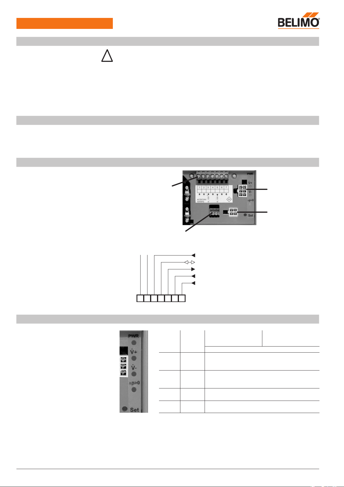
Electrical connections
Front panel
Assignment of terminals 1 ... 7
Terminals 1 ... 7
for supply and control
Tab connection for
damper actuator
Tab connection for
pressure sensor
Diagnostics socket for VRP-M-Tool
AC 24 V
DC 24
V
~
T
+
_
1
2
3
4
5
6
7
T
~
+
MPw U5 z1 z2
VAV reference signal
min
...
max
PP/MP signal
Volumetric flow actual value 0 ... 100%
nom
OPEN operating step
CAV operating step CLOSED /
min
/
mid
/
max
LED indicator and address pushbutton
PWR Green LED LED on:
– AC/DC 24 V supply OK
– Device ready
LED off:
– Supply failure
– Device defective
Blinking
– If Set pushbutton pressed during MP adressing
+ Red LED LED on:
– Volumetric flow > setpoint = damper closes
or is closed
– Red LED LED on:
– Volumetric flow < setpoint = damper opens
or is open
∆p>0 Yellow LED Zero offset of VFP-.. pressure sensor
(refer to page 6 for procedure)
Set Pushbutton for assigning MP address in bus operation
(refer to page 18 for procedure)
Page 9
VRP-M VAV
Adaptive VAV controller
www.belimo.eu Product information S4-VRP-M VAV • en • v2.0 • 11.2006 • Subject to changes 9 / 28
Functions
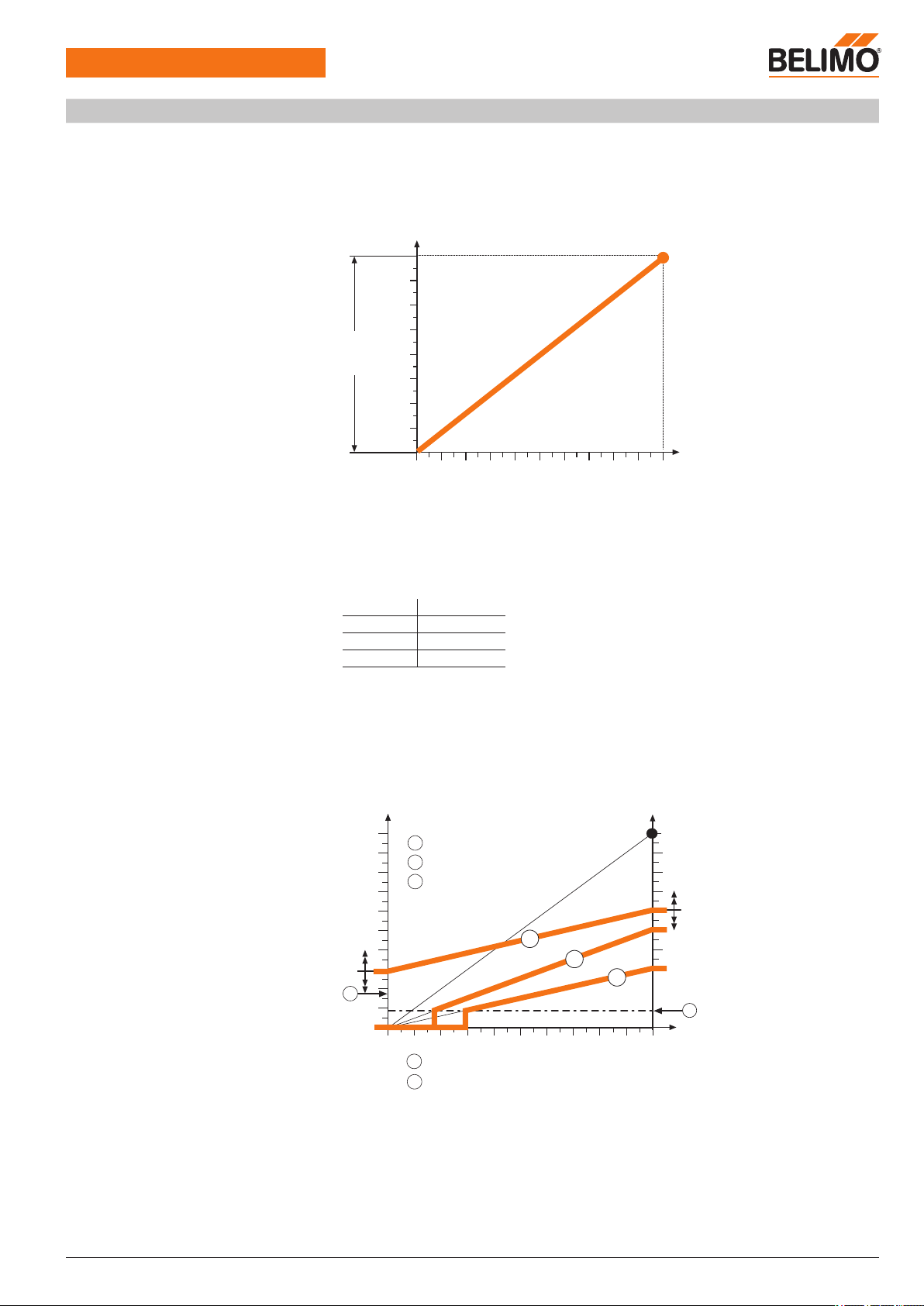
Nominal volumetric flow
nom
nom
corresponds to the maximum volumetric flow of the VAV unit at which the pressure drop
and noise are still within the permissible operating conditions. The
nom
values are specified and
fixed-programmed by the unit manufacturer.
The volumetric flow actual value signal U5 is always in relation to
nom
. Changes in the opera-
ting volumetric flow settings
min
and
max
therefore have no influence on the U5 voltage signal.
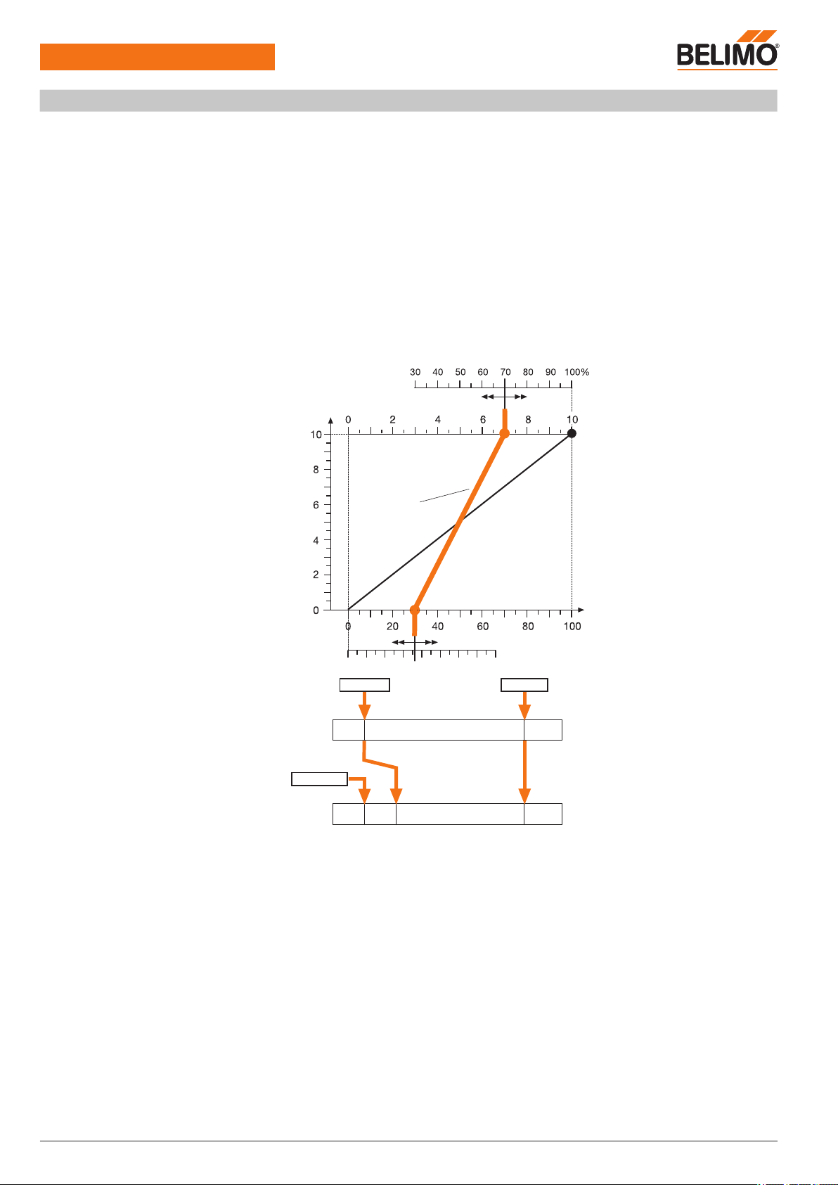
Creep flow limitation
Minimum setting limit
max
Creep flow limitation (1)
This function suppresses differential pressure signals in the zero region. Undefined actuator movements in the 1 ... 6 Pa differential pressure range are prevented by this limitation. The working
range is physically limited owing to the dynamic behaviour of the differential pressure sensor and
the flow pattern of the media.
Sensor type Limitation
VFP-100 1 Pa
VFP-300 3 Pa
VFP-600 6 Pa
Unit manufacturer’s minimum setting limit (2)
Oversized VAV units can make control more difficult in the lowest differential pressure range.
A minimum volumetric flow, usually corresponding to a differential pressure of approximately
5 ... 12 Pa, is therefore specified for the units by the manufacturer. Functional restrictions in this
range can be avoided by complying with the unit manufacturer’s volumetric flow setting.
0/2
10
[V]
2
30%
0%
100%
100%
2
1
a
b
c
a
b
c
1
Start point
End point
nom
Volumetric flow [
nom
]
Volumetric flow actual value signal U5 [V]
Setting
[
min
]
Setting
[
max
]
Reference signal w
Optimum range
Setting with restriction
Setting with greatest
restriction
Creep flow limitation <2 Pa
Unit manufacturer’s minimum setting limit
0 ... 10 V
2 ... 10 V
adjustable
Page 10
VRP-M VAV
Adaptive VAV controller
10 / 28 Product information S4-VRP-M VAV • en • v2.0 • 11.2006 • Subject to changes www.belimo.eu
Functions
(Continued)
Control tolerance
The maximum permissible control tolerance is defined as a percentage of the nominal volumetric
flow nom. If the system deviation exceeds or undershoots this tolerance, the actuator is adjusted
so that the volumetric flow actual value corresponds to the required setpoint.
Control tolerance: ±5% of
nom
The two LEDs [+p] and [-p] indicate when the maximum control tolerance is exceeded or undershot or when the deviation is being corrected by means of an actuator movement:
LED [+p]: Volumetric flow actual value > (setpoint + control tolerance) = damper closes
LED [-p]: Volumetric flow actual value < (setpoint + control tolerance) = damper opens
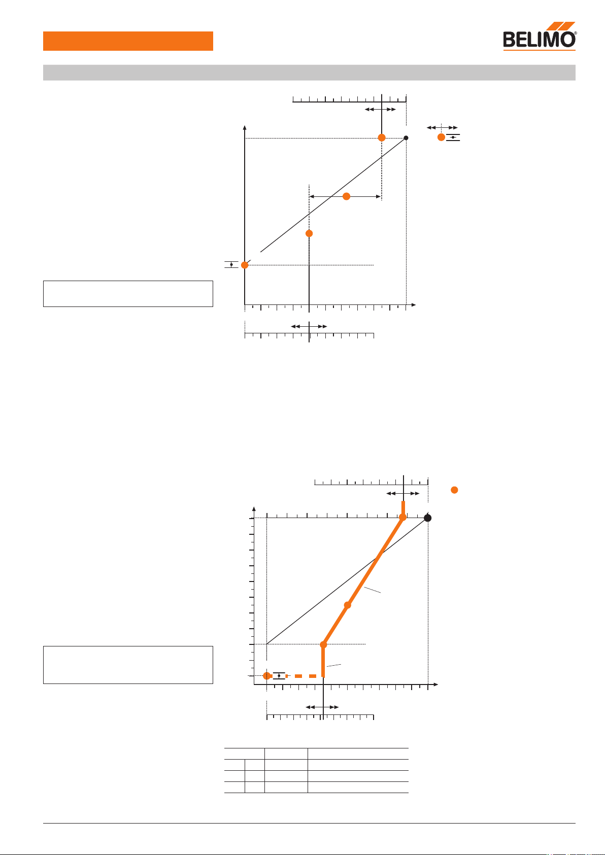
VAV operating volumetric flow
min
...
max
setting
In variable operation, the volumetric flow is specified by means of the reference signal in the
min
...
max
range.
–
max
forms the upper limit value as a function of the nominal volumetric flow.
Range 30 ... 100% of
nom
.
–
min
forms the lower limit value as a function of
nom
.
Range 0 ... 100% of
nom
.
Voltage level
0,0
10
0,0
0,1
10
2,0
min
0…10 V
2…10 V
max
max
min
In mode 2 ... 10 V, it is possible to achieve shut-off mode (damper CLOSED) by lowering the
reference signal to 0.0 V.
For override control in VAV operation, for example CLOSED or OPEN, the reference signal w
(input 3) can be overridden by connecting control inputs 6 (z1) and 7 (z2).
CAV operating steps
CLOSED /
min
/
mid
/
max
/ OPEN
Five operating steps are available for step operation:
– Shut-off operation – damper CLOSED: The damper is moved into the CLOSED position in a
defined manner.
– Operating steps
min
/
mid
/
max
: The VRP-M adjusts the volumetric flow to the fixed selected
value.
– Flushing operation – damper OPEN: The damper can be opened for maximum ventilation, in
which case air volume control is deactivated.
The operating mode control signals are connected to inputs 6 (z1) and 7 (z2). If signals appear
at these two inputs simultaneously, input 6 (z1) for the OPEN function takes priority.
Reference signal w
[V]
nom
max
[
min
]
Variable operation
Volumetric flow [%
nom
]
Volumetric flow actual value signal U5 [V]
Example: 0 ... 10 V mode
< Modulating operation >
Start point End point
Shut-off
[
max
]
Mode:
CLOSED
< Modulating operation >
Page 11
VRP-M VAV
Adaptive VAV controller
www.belimo.eu Product information S4-VRP-M VAV • en • v2.0 • 11.2006 • Subject to changes 11 / 28
Functions
(Continued)
Note
mid
is not available with DC 24 V supply.
100%
30 40 50 60 70 80 90
0
100
10
20
30
50
60
70
80
90
40
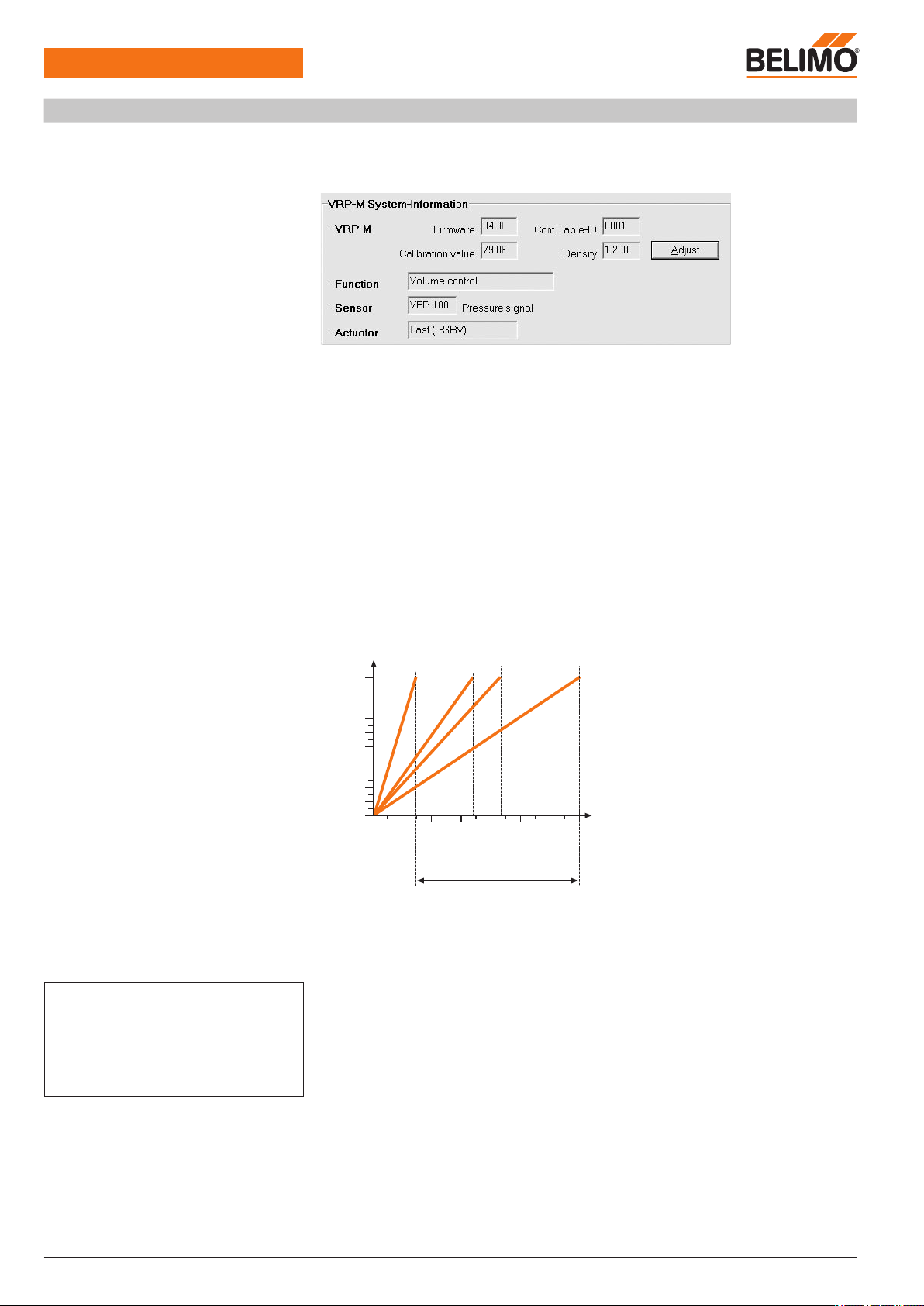
VAV override operation
CLOSED /
min
/
mid
/
max
/ OPEN
If necessary, the VAV
min
...
max
range can be overridden by fixed operating steps in VAV ap-
plications.
The following operating steps are available:
– Shut-off operation – damper CLOSED: The damper is moved into the CLOSED position in a
defined manner.
– Operating steps
min
/
mid
/
max
: The VRP-M adjusts the volumetric flow to the fixed selected
value.
–
Flushing operation – damper OPEN: The damper can be opened for maximum ventilation, in
which case air volume control is deactivated.
Note
–
min
: All inputs (3 / 6 / 7) open.
–
mid
is not available with DC 24 V supply.
8
6
2
4
30
40
100%
30 40 50 60 70 80 90
0
100
10
20
50
60
70
80
90
10
0
10
2
4
6
8
Priorities for reference value input 3 (w)
and control inputs 6 (z1) / 7 (z2)
If several signals appear simultaneously, they are processed acc. to the following priorities:
Terminal Priority Function
6 z1 1 OPEN
7 z2 2 CLOSED /
min
/
mid
/
max
3 w 3
min
…
max
Reference signal w
[V]
CAV operating mode
OPEN
(depending on supply pressure)
nom
max
mid
min
CLOSED
[
min
]
Volumetric flow [%
nom
]
[
max
]
Volumetric flow [%
nom
]
[
max
]
ZU
OPEN
nom
max
mid
[
min
]
Constant operation
Variable operation
Constant operation
min
Volumetric flow actual value signal U5 [V]
Example: 2 ... 10 V mode
Page 12
VRP-M VAV
Adaptive VAV controller
12 / 28 Product information S4-VRP-M VAV • en • v2.0 • 11.2006 • Subject to changes www.belimo.eu
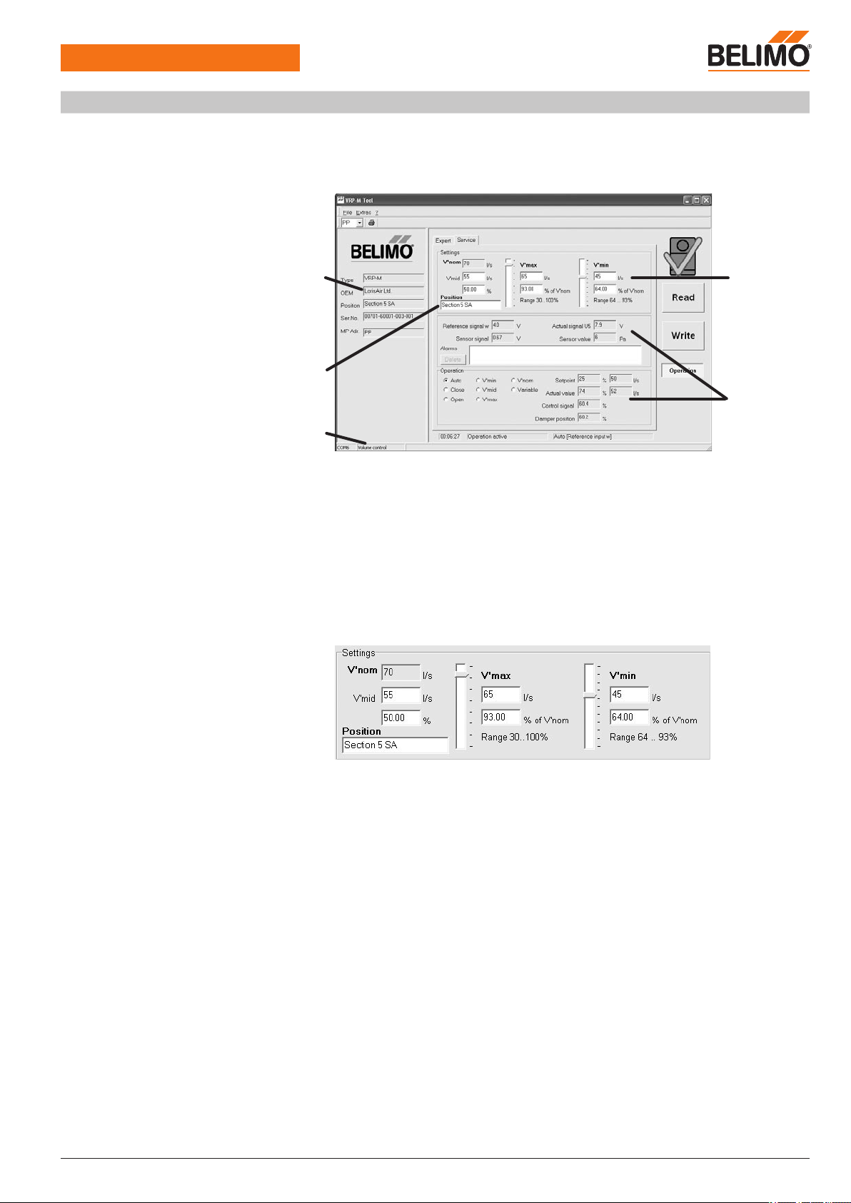
System configuration
Unit manufacturer’s settings
The system solution selected by the unit manufacturer is mounted by the latter on the VAV unit
and configured according to the system requirements (as stated in the order). This configuration
comprises the following settings.
VRP-M Tool
Expert tab
System information
Function
Volumetric flow
Sensor
The pressure sensor type is specified to enable the pressure range to be adapted.
Actuator
The actuator type is specified to enable the running time characteristics to be adapted.
Control – reference signal w,
volumetric flow actual value signal U5
The reference signal w and the volumetric flow actual value signal U5 are adapted to the MCR
system.
Selection: DC 0...10 V / DC 2...10 V / adjustable (sequence matching in the 0...10 V range)
Calibration –
nom
The
nom
values are specified and fixed-programmed by the unit manufacturer.
Each VRP-M system solution is optimally adapted to the VAV unit by means of the
nom
setting.
nom
corresponds to the maximum volumetric flow of the VAV unit at which the pressure drop
and noise are still within the permissible operating conditions. The
nom
setting is specified by
the unit manufacturer.
0
10
2
4
6
8
NW...
NW...
NW100
NW...
Replacement orders
If replacement devices are ordered, they must be parameterised beforehand by the OEM at the
factory according to the installed system. The VRP-M is sold exclusively via the OEM channel for
this reason.
Note
The equipment configuration and settings form part
of the unit manufacturer’s system solution (OEM)
and are not allowed to be modified without prior
authorisation. All changes are liable to disrupt opera
tion and cause damage to the system or injury to
persons!
Volumetric flow
actual value signal U5
[V]
Volumetric flow [
nom
]
nom
Smallest
nominal width
Largest
nominal width
OEM unit range
Page 13
VRP-M VAV
Adaptive VAV controller
www.belimo.eu Product information S4-VRP-M VAV • en • v2.0 • 11.2006 • Subject to changes 13 / 28
VRP-M Tool – Operating data settings
Adjustments on the system with VRP-M-Tool
The VRP-M-Tool can be used to adjust the operating data (
min
,
mid
,
max
settings) and the
reference signals (mode setting – voltage range) directly on the system if necessary. The VRPM-Tool adapter must be connected to the diagnostics socket on the VRP-M or to the MP connection routed to the terminals for this purpose (see Note on page 15).
VRP-M-Tool
Service tab
1 Identification
2 Operating volumetric flow settings
3 System designation entry
4 Volumetric flow
5 Operational test:
Reference signal
Differential pressure [pascal]
Setpoint / actual value [m3/h, l/s]
Selected operating mode:
– AUTO / CLOSED / OPEN
–
min
/
mid
/
max
/
nom
– Variable setpoint (
min
...
max
)
Operating volumetric flow settings
These parameters are used to set the VAV unit to the air volumes required for each application.
The settings are based on the air volumes calculated by the planning engineer and can either be
preset by the VAV unit manufacturer or adjusted on the system using the VRP-M-Tool.
max
Range 30...100% of
nom
Upper volumetric flow limit
min
Range 0 ...100% of
nom
Control range x * ...100% of
nom
Lower volumetric flow limit
Shut-off operation (CLOSED) according tomin setting
If a shut-off function is required in VAV operation, it can be achieved by setting
min
0%.
mid
Range 0 ...100% of
min
...
max
An intermediate position
mid
is available for constant air volume (CAV) applications to facilitate
finer steps.
*
min
settings lower than the control range
min
values that are lower than the start value indicated in this range can be set, for example, if the
VAV unit has a shut-off function
System designation entry
Input field (16 characters) for specific system designations, e.g. MCR address, system name,
item number in diagram, etc.
1
3
2
5
4
Page 14
VRP-M VAV
Adaptive VAV controller
14 / 28 Product information S4-VRP-M VAV • en • v2.0 • 11.2006 • Subject to changes www.belimo.eu
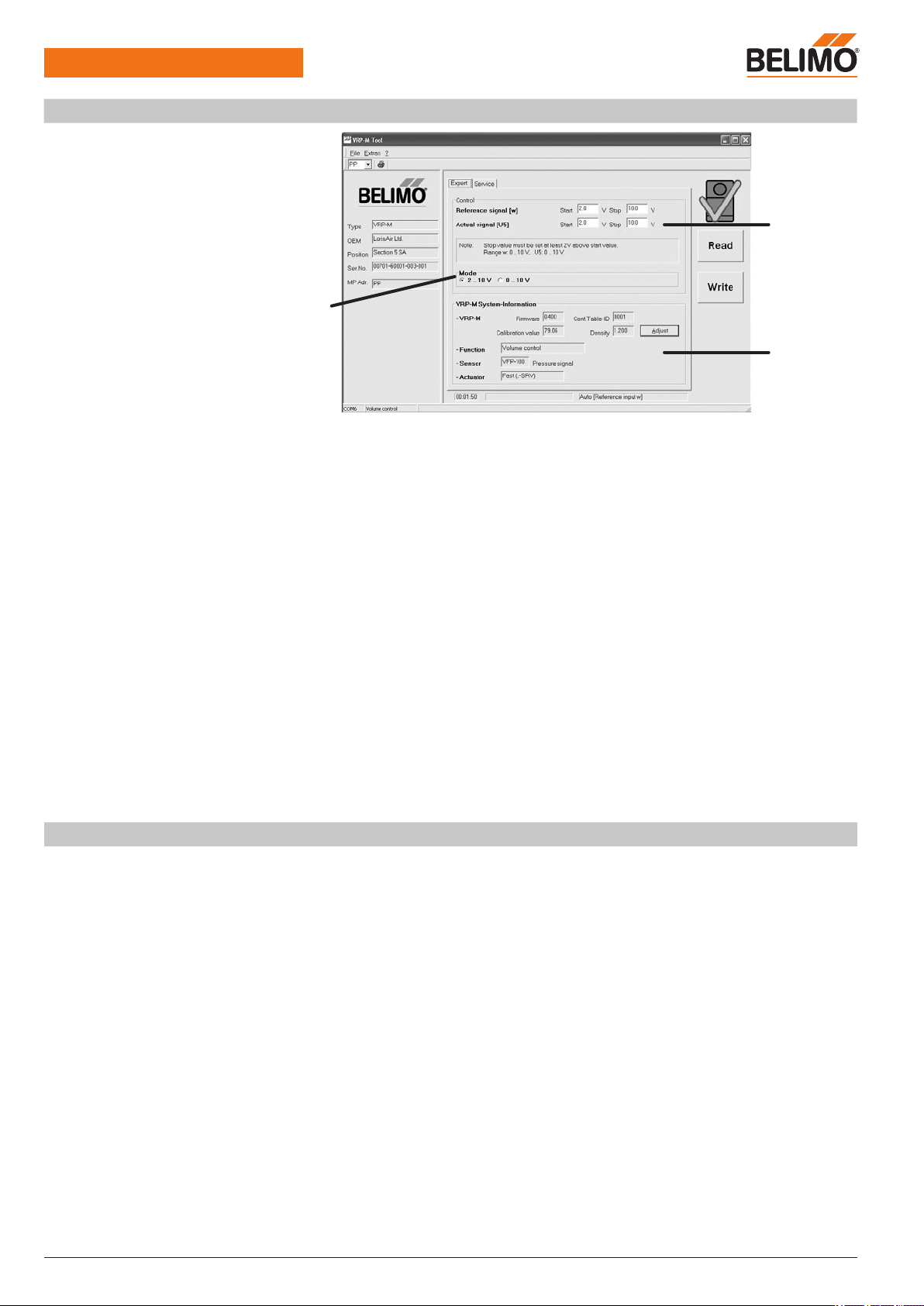
VRP-M Tool – Operating data settings
(Continued)
VRP-M-Tool
Expert tab
1 Mode setting
Standard 0 ... 10 / 2 ... 10 V
2 Control
System-specific settings
– Reference signal w
– Volumetric flow actual value signal U5
3 VRP-M system information
– VRP-M
Version and conductance setting
– Volumetric flow function
– Sensor type
– Actuator type
Mode setting
Options: 0... 10 V / 2...10 V / system-specific
The mode setting acts on the reference signal w and the volumetric flow actual value signal U5.
Variable settings are displayed here and can also be reset by selecting 2 ... 10 / 0 ... 10 V. Variable settings are entered in the «Control» field above.
Control
Variable setting
It is sometimes essential to adapt the reference signal w or the volumetric flow actual value signal U5 to the MCR system directly on the control system.
The reference signal w and the volumetric flow actual value signal U5 can be set to different values (e.g. reference signal w: 2...10 V / actual value signal U5: 0...10 V).
Reference signal [w] / working range
min
...
max
Start point: DC 0.0 ... 8 V
Stop point: DC 2.0 ... 10 V
Volumetric flow actual value signal [U5] / display range 0...100%
nom
Start point: DC 0.0 ... 8 V
Stop point: DC 2.0 ... 10 V
1
2
3
VRP-M-Tool – Availability
The current version of the VRP-M-Tool and the associated documentation can be downloaded
from www.belimo.eu.
Page 15
VRP-M VAV
Adaptive VAV controller
www.belimo.eu Product information S4-VRP-M VAV • en • v2.0 • 11.2006 • Subject to changes 15 / 28
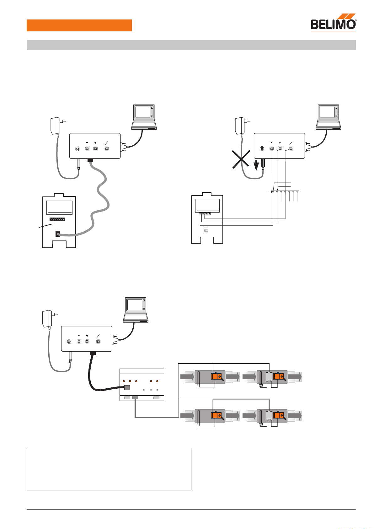
Connection of the VRP-M-Tool
The VRP-M-Tool required for settings and servicing can be connected either directly to the 3-pin service socket on the VRP-M controller or via
the MP connection (terminal 4). A level converter is required for communication, e.g.: ZIP-RS232.
Conventional operation (PP)
VRP-M runs with a locally connected reference signal (0 ... 10 V on connection 3). VRP-M detects that there is no tool connected and switches
back to the connected analogue reference signal automatically after 120 s.
VRP-M
AC 24 V
ZIP-RS232
1
2
5
OFF
Actuator
RS232
ON
U
PP
~
T
AC 230 V
ZN230-24
VRP-M
Tool
~
T
+
_
4.21
AC/DC 24 V
VRP-M
. . .
124
ZIP-RS232
1
2
5
OFF
Actuator
RS232
ON
U
PP
~
T
AC 230 V
ZN230-24
VRP-M
Tool
24 VAC
MP-Bus mode
VRP-M runs in the MP system, which means it obtains its reference signal via the connected MP master, e.g. UK24LON.
The VRP-M-Tool can only be connected via the bus master in MP mode, otherwise there would be two MP masters connected to the MP-Bus.
This means the local connection to the VRP-M cannot be operating at the same time as the MP master.
MP 1
MP-Bus
MP ..
UK24LON
2
MP 8
MP ..
AC 24 V
ZIP-RS232
1
2
5
OFF
Actuator
RS232
ON
U
PP
~
T
AC 230 V
ZN230-24
VRP-M
Tool
-
+
-
+
Note
• The service plug integrated in the VRP-M is not available with bus operation.
• The MP-Bus cannot be used to transmit control functions if it is also used to
connect the VRP-M-Tool.
Workaround: Disconnect the MP-Bus (terminal 4) and use the local MP plug
instead.
AC/DC
24 V
Connection in control cabinetConnection via service socket
LON application with UK24LON
Page 16
VRP-M VAV
Adaptive VAV controller
16 / 28 Product information S4-VRP-M VAV • en • v2.0 • 11.2006 • Subject to changes www.belimo.eu
Bus operation
The VRP-M system solution can be interconnected with other Belimo MP actuators (damper
actuators, valve actuators, VAV-Compact controllers, VRP-M system solutions) thanks to the
integrated communication principle over the Belimo MP-Bus. Up to eight Belimo MP devices are
supplied with a digital control signal by the higher-level bus master and then opened to the position dictated by this signal.
The switch-over from conventional to bus operation is automatic as soon as the MP actuator is
assigned an MP address (1...8).
Belimo MP devices can be integrated into the following systems:
– LONWORKS®: The variables of Functional Profile 8110 can be used in conjunction with the
Belimo UK24LON interface.
– EIB Konnex: Can be used with the Belimo UK24EIB interface
– DDC controller with an integrated MP-Bus protocol: Available from several manufacturers
Damper position (From VRP-M version V3.x)
(nvoAbsAngle - absolute actuator position in angular degrees (°))
The feedback signal, i.e. the network variable nvoAbsAngle, is not available for applications with
NM24-V-ST actuators (old actuator generation).
MP-Bus cycle time
The MP-Bus cycle time must be noted when integrating setpoints and actual values. It is typically
2...8 s, depending on the number of connected bus users and integrated sensors.
The local VRP-M control function is not affected by the cycle time. The cycle time of the MP-Bus
must always be taken into account, however, when selecting setpoints via the MP-Bus.
Mode of operation
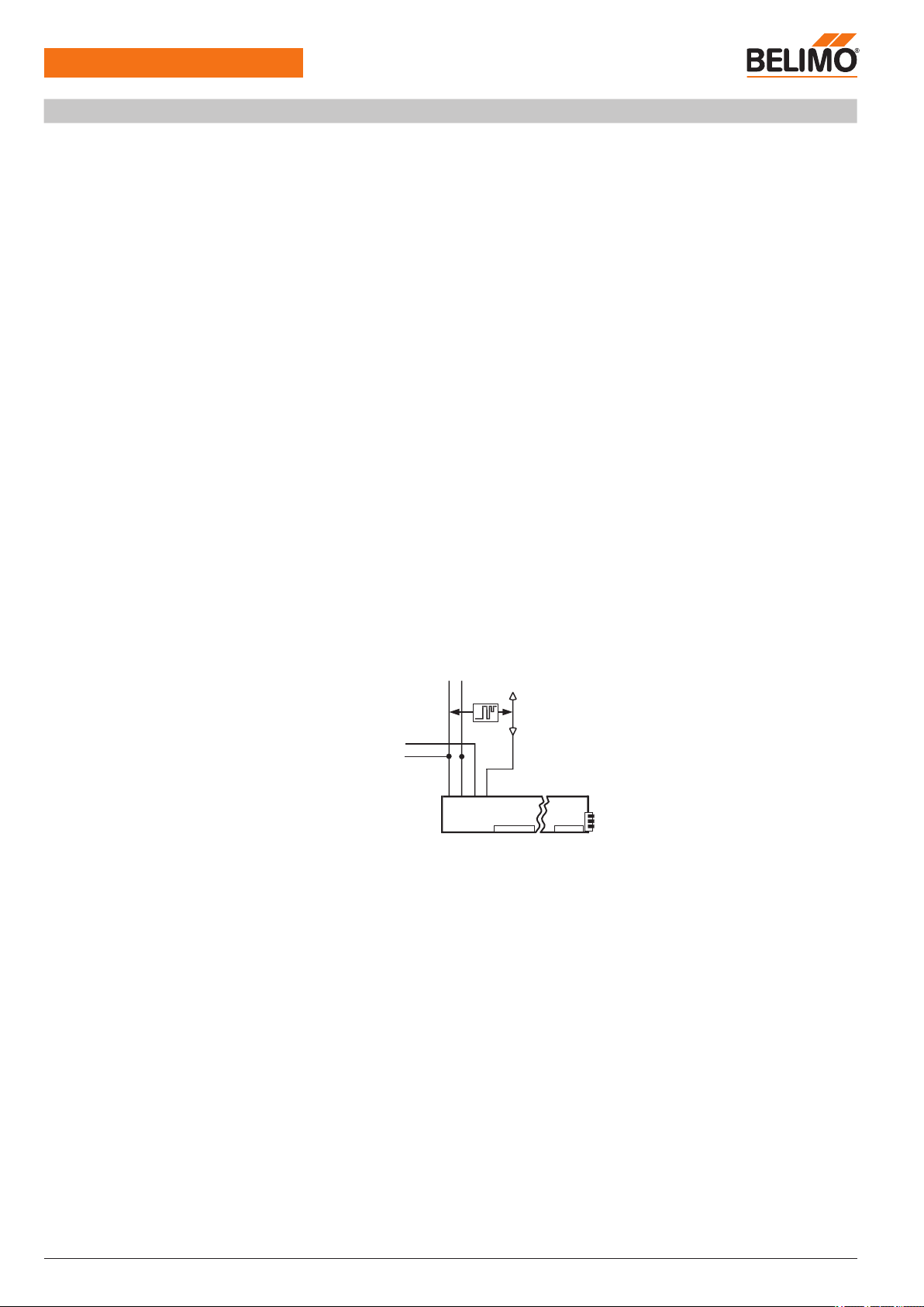
Sensor integration (From VRP-M version V3.x)
The VRP-M can be connected to an additional active 0 ... 10 V signal in MP-Bus mode independently of the VAV control loop. The sensor signal is connected to the reference value input
that is not used in MP-Bus mode (connection 3).
The VRP-M then acts as an analogue/digital converter for transmitting the sensor signal to the
higher-level system. This system must know the physical address (which sensor is connected to
which MP device) and be capable of interpreting the corresponding sensor signal.
Active sensor connection
MP
4321 VRP-M
PPw
~
T
+
_
5 6 7
U5 y z
~
T
T
+
_
0 … 10
V
DC 24 V
Active 0 ... 10 V sensors for open and closed-loop control functions in the higher-level system,
such as moisture or CO2 sensors. The cycle time must be taken into account in the implementation!
Reference signal w setting if an active sensor is connected: 0 ... 10 V
Integration of switches,
passive resistance sensors
The VRP-M only supports active sensors with a 0 ... 10 V output; i.e. no switches or passive
sensors (resistance elements) can be integrated.
Principle of VRP-M in bus operation
In bus operation, the VRP-M controller receives its reference signal from the higher-level control
system and adjusts the volumetric flow to the fixed selected value in the
min
...
max
range.
If necessary, the VAV
min
...
max
range can be overridden by fixed operating steps (control
inputs z1 and z2) in bus operation.
The following operating modes are available:
– Shut-off operation – damper CLOSED: The damper is moved into the CLOSED position in a
defined manner.
– Operating steps
mid
/
min
: The VRP-M adjusts the volumetric flow to the fixed selected value.
– Flushing operation – damper OPEN: The damper can be opened for maximum ventilation, in
which case air volume control is deactivated.
Sensor
Page 17
VRP-M VAV
Adaptive VAV controller
www.belimo.eu Product information S4-VRP-M VAV • en • v2.0 • 11.2006 • Subject to changes 17 / 28
Bus operation
(Continued)
Note
mid
not available with DC 24 V supply.
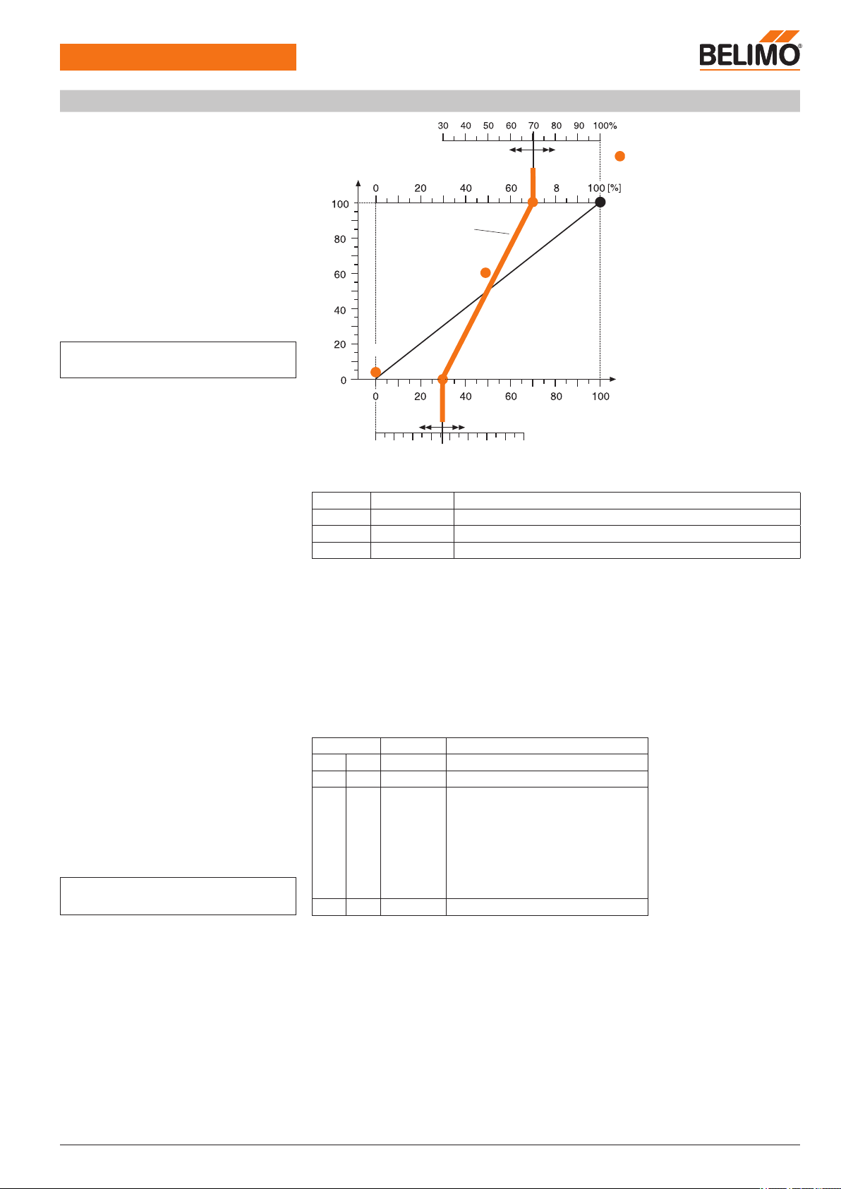
Operating volumetric flow setting
min
/
max
The setpoint selected over the MP-Bus is resolved by means of the
min
and
max
settings on
the VRP-M.
Function Volumetric flow Range
nom
Nominal OEM-specific value, depending on the application and the VAV unit type
max
Maximum 30 ... 100% of
nom
min
Minimum 0 * ... 100% of
nom
* The minimum volumetric flow setting
min
varies according to the type of VAV unit and is also influenced
by the creep flow limitation function (see «Creep flow limitation / minimum setting limit»).
Open operating volumetric flow setting
The
min
-/
max
setting can be left open if necessary, i.e.
min
0% /
max
100%. In this case, the
volumetric flow must be limited in the higher-level system.
This operating setting allows the limitation of the volumetric flow to be adjusted without altering
the parameters on the VAV controller.
Responsibility for the limiting function passes from the unit manufacturer to the system supplier
or integrator.
Priorities for bus signal (MP setpoint)
and control inputs 6 (z1) / 7 (z2)
Note
Note the speed of the MP-Bus!
If several signals appear simultaneously, they are processed according to the following table of
priorities.
Terminal Priority Function
6 z1 1 OPEN
7 z2 2 CLOSED /
min
/
mid
/
max
3 MP override function
1 OPEN
2 CLOSED
3
max
4
min
5
mid
6 –
7
nom
4 MP setpoint 0 ... 100% =
min
...
max
Last setpoint
Bus fail function
The VRP-M saves the current setpoint, i.e. the last setpoint to have been received from a bus
master (VRP-M-Tool, UK24LON). If the MP network fails, the connected VRP-M detects this and
retains this setpoint until it receives a new one from the MP master.
Initial setpoint after power failure
The VRP-M starts with its MP initial status (setpoint 0%, corresponding to
min
setting) if a power
failure occurs in the intervening period.
Reference signal
(e.g. UK24LON nviRelStpt)
[%]
[
max
]
CLOSED
OPEN
nom
max
mid
[
min
]
min
Volumetric flow actual value signal
(e.g. UK24LON nvcActualValue)
Volumetric flow [%
nom
]
Reference signal
(e.g. UK24LON nviRelStpt)
Page 18
VRP-M VAV
Adaptive VAV controller
18 / 28 Product information S4-VRP-M VAV • en • v2.0 • 11.2006 • Subject to changes www.belimo.eu
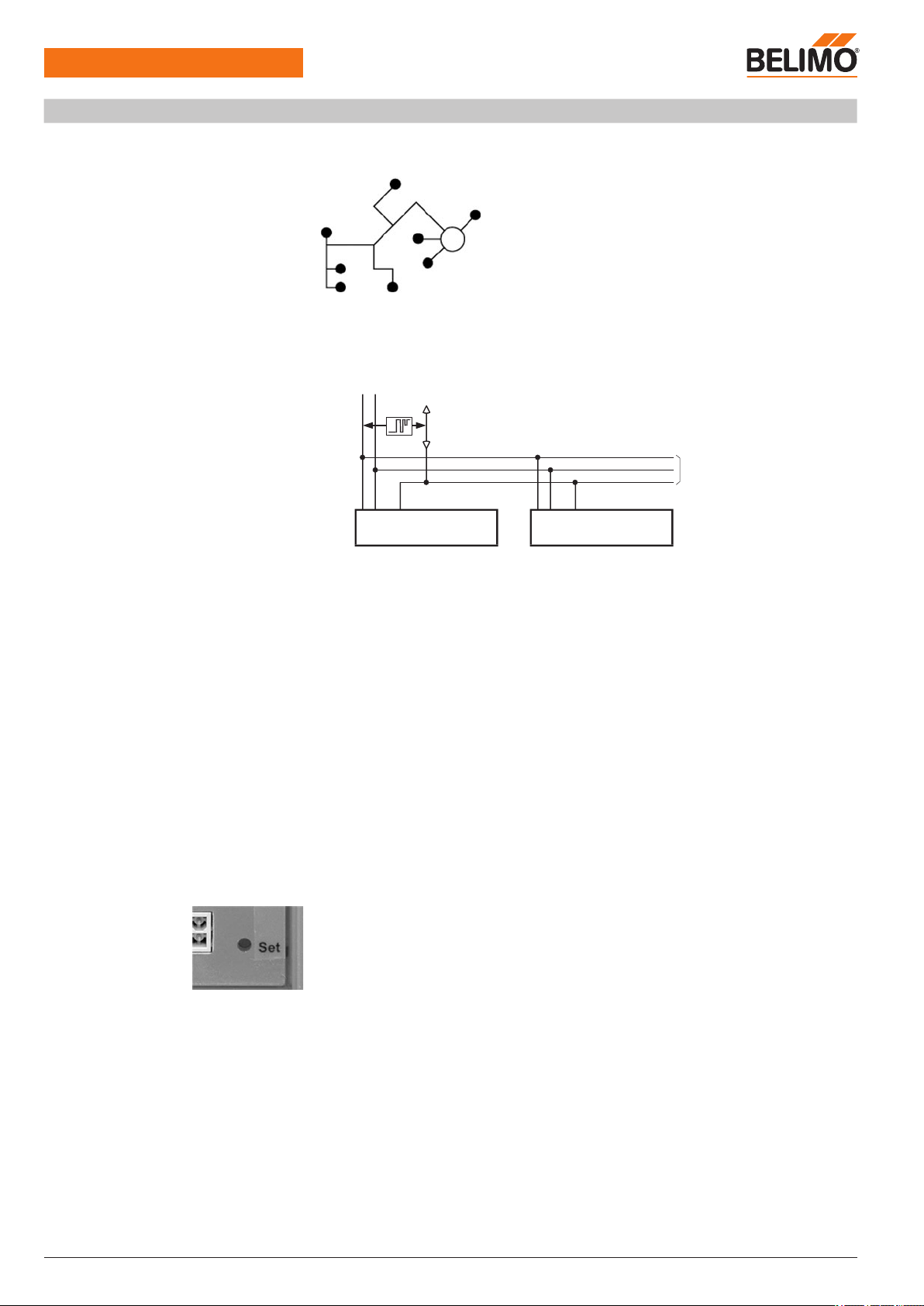
MP-Bus
Topology
The cables of up to eight actuators can be laid in a freely definable topology. The following topologies are permitted: Star-shaped, ring-shaped, tree-shaped or mixed forms.
Connection
The network consists of a 3-pin connection (MP communication and 24 V supply). Neither
special cables nor terminating resistors are required. Power can be supplied either over the bus
cable or from a local power supply.
MP
4321 VRP-M
MPw
~
T
+
_
5 6 7
U5 z1 z2
4321 VRP-M
MPw
~
T
+
_
5 6 7
U5 z1 z2
~
T
+
_
AC 24
V
DC 24
V
Network
Up to eight MP actuators can be connected in a network (VAV-Compact, VRP-M etc.).
Supply with AC or DC voltage
Nominal voltage AC 24 V, 50/60 Hz DC 24 V
Power supply range AC 19.2...28.8 V DC 21.6...26.4 V
Wire sizing See «Technical data», page 7
Length of MP-Bus cable
The cable lengths are limited:
– By the sum of the performance data of the connected devices, VAV controllers and actuators
– By the type of supply (AC 24 V or DC 24 V)
– By the cable cross-section
For more information about planning and installation, see www.belimo.com
– VAV-Compact NMV-D2-MP Product Information
– Bus and communication systems section
Addressing
If the VRP-M system solution is integrated in a bus system, each connected VRP-M must be
assigned an MP address in the range 1 ... 8.
Procedure
– Start the addressing procedure on the MP-Bus master with the VRP-M-Tool, UK24LON, etc.
– Refer to the bus master documentation for further details
– Procedure with VRP-M-Tool:
a) Select the address by means of the serial number
Enter the serial number of the VRP-M (sticker on VRP-M, displayed in VRP-M-Tool)
b) Select addressing with acknowledgement on the VRP-M
Acknowledge the selected address by pressing the Set pushbutton on the required VRP-M
The power LED (green) blinks when the Set pushbutton is pressed
Up to 8 MP-Bus users
More MP-Bus users
Page 19
Technical data sheet VFP-.. sensors
www.belimo.eu Product information S4-VRP-M VAV • en • v2.0 • 11.2006 • Subject to changes 19 / 28
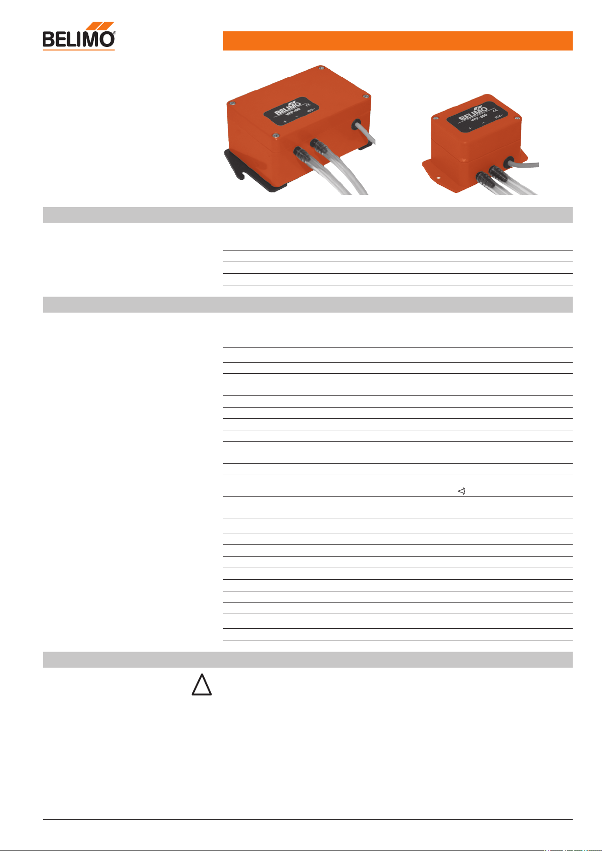
Static differential pressures sensor
for neutral to slightly aggressive gases
VFP-100
VFP-300
VFP-600
Technical data
Electrical data
Power supply
Connection
DC 15 V (from VRP-M controller)
1 m cable with 4-pin plug
(compatible with VRP-M controller)
Functional data
Measuring range See «Overview of types»
Overload protection See «Overview of types»
Measuring principle Diaphragm differential pressure measurement
(inductive)
Medium Neutral to slightly aggressive gases
Parts in contact with medium Ni, Al, CuBe, PU
Linearity ±1% of final value (FS)
Hysteresis Max. 0.1% of final value
Temperature sensitivity Zero
Measuring range
See «Overview of types»
t = +10 ... 40°C (reference temperature t0 = 25°C)
Mounting position Upright (connection on bottom or side)
Position dependency Max. ±4.5 Pa
when rotated 90° about horizontal axis
Pressure port Hose connection
for hose with 4 ... 6 mm internal diameter
Safety
Protection class III Safety extra-low voltage
Degree of protection IP42
EMC CE according to 89/336/EEC
Mode of operation Type 1 (to EN 60730-1)
Ambient temperature range 0 ... +50°C
Non-operating temperature –10 ... +70°C
Ambient humidity range 5 ... 95% r.H., non-condensating (EN 60730-1)
Maintenance Maintenance-free
Dimensions/weight
Dimensions See «Dimensions» on page 25
Weight See «Overview of types»
Overview of types
Type Measuring ranges Overload protection
Temperature sensitivity
of zero
Weight
VFP-100 0 ... 100 Pa max. 500 Pa
±0.1% / K Approx. 500 g
VFP-300 0 ... 300 Pa max. 5’000 Pa ±0.05% / K Approx. 280 g
VFP-600 0 ... 600 Pa max. 3’000 Pa ±0.05% / K Approx. 280 g
Safety notes
!
• The sensors are not allowed to be used outside the specified field of application, especially in
aircraft or in any other airborne means of transport.
• They may only be installed by suitably trained personnel.
All applicable legal or institutional installation regulations must be complied with.
• The devices do not contain any parts that can be replaced or repaired by the user.
• The devices contain electrical and electronic components and are not allowed to be disposed
of as household refuse. All locally valid regulations and requirements must be observed.
Page 20

VFP-..
Static differential pressure sensors
20 / 28 Product information S4-VRP-M VAV • en • v2.0 • 11.2006 • Subject to changes www.belimo.eu
Product features
Application
Together with a VRP-M controller and a Belimo NM..-ST actuator, the VFP-.. static pressure
sensors form a control system for pressure-independent variable (VAV) and constant (CAV) air
volume controls.
The pressure sensors are used for static differential pressure measurement with differential
pressure pickups installed in air ducts. They are also suitable for contaminated or slightly aggressive air 1). Their robust design makes them ideal for installation in laboratories, clean room
systems and industrial applications.
Mode of operation
A high-quality metal diaphragm is used in the sensor. The measured pressure produces a corresponding diaphragm stroke, which is detected inductively and converted to a pressure-linearised
output signal.
The measuring signal is influenced by the mounting position due to the dead weight of the diaphragm. The sensor is calibrated at the factory in the vertical position, but can be readjusted on
site if necessary, e.g. in order to mount it in another position.
The temperature is compensated to reduce drift to a minimum. The wear-free, inductive measurement method guarantees maintenance-free operation.
1) See «Technical data», page 19
For zero offset and more information, see «System description», page 6
Electrical installation
The ready-to-connect sensor unit is connected to the VRP-M controller with the 4-pin plug.
Page 21
Technical data sheet NMQB24-SRV-ST actuator
www.belimo.eu Product information S4-VRP-M VAV • en • v2.0 • 11.2006 • Subject to changes 21 / 28
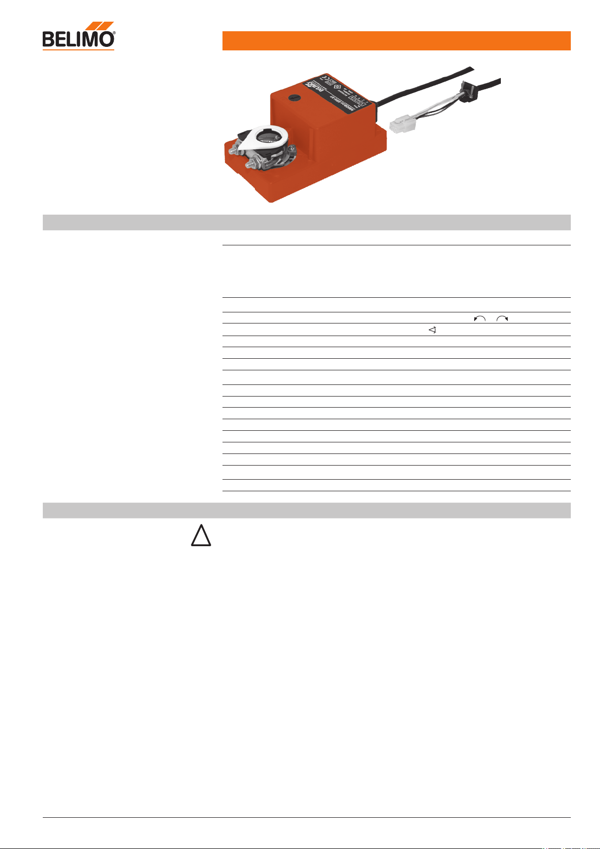
Fast-running damper actuator
for VRP-M system solution
Technical data
Electrical data
Power supply AC/DC 24 V (from VRP-M controller)
Power consumption In operation
At rest
For wire sizing
Connection
9 W
<1.2 W
12 VA (lmax. 8.3 A @ 5 ms)
Cable with 6-pin plug
(compatible with VRP-M controller)
Functional data
Torque (nominal torque) Min. 4 Nm @ nominal voltage
Direction of rotation Reversible with switch or
Angle of rotation
Max. 95° , mechanical end stops adjustable
Permissible range of rotation 63 ... 95%
Running time 5 s
Sound power level 52 dB (A)
Safety
Protection class III Safety extra-low voltage
Degree of protection IP54 (cable entry at bottom)
EMC CE according to 89/336/EEC
Mode of operation Type 1 (to EN 60730-1)
Ambient temperature range –30 ... +50°C
Non-operating temperature –40 ... +80°C
Ambient humidity range 5 ... 95% r.H., non-condensating (EN 60730-1)
Maintenance Maintenance-free
Dimensions/weight
Dimensions See «Dimensions» on page 25
Weight Approx. 900 g
Safety notes
!
• The actuator is not allowed to be used outside the specified field of application, especially in
aircraft or in any other airborne means of transport.
• It may only be installed by suitably trained personnel.
All applicable legal or institutional installation regulations must be complied with.
• The device does not contain any parts that can be replaced or repaired by the user.
• The actuator is synchronised when the supply voltage is switched on or when the manual
override switch is actuated. The actuator or the damper blade is moved into the «CLOSED»
position in a defined manner and then into the position dictated by the system.
• The device contains electrical and electronic components and is not allowed to be disposed
of as household refuse. All locally valid regulations and requirements must be observed.
Page 22
NMQB24-SRV-ST
Fast-running damper actuator for VAV and CAV units
22 / 28 Product information S4-VRP-M VAV • en • v2.0 • 11.2006 • Subject to changes www.belimo.eu
Product features
Simple direct mounting
Simple direct mounting on the damper spindle with a universal spindle clamp, supplied with an
anti-rotation strap to prevent the actuator from rotating.
Manual control
Manual operation with self-resetting pushbutton.
The position calculation is synchronised in order to prevent deviations as a result of manual
control. This synchronisation also permits a simple functional check (see «Synchronisation»
below).
Adjustable angle of rotation
Caution!
Adaptation is necessary when the system is
commissioned or whenever the end stops for angle
of rotation limiting are adjusted (press the pushbutton twice).
!
The angle of rotation is adapted to the available setting range by the manufacturer of the damper by
means of integrated, mechanical end stops.
Permissible range: 63 ... 100%.
Adaptation to the available angle of rotation
This function detects the upper and lower spindle end stops and stores them in the actuator. The
running time and the working range are adapted to the available angle of rotation. Detection of
the mechanical end stops enables a gentle approach to the end position and protects the actuator and damper mechanisms.
Synchronisation
The actuator moves into the «CLOSED» position (left or right end stop, depending on the position of the direction of rotation switch) when the supply voltage is switched on, in the event of a
power failure >5 s or if the pushbutton is actuated again. It then moves into the position required
by the system.
Functional check
Correct functioning of the dampers can be checked extremely easily: The gearing latch can be
disengaged simply by pressing a pushbutton on the housing. As long as the pushbutton remains
pressed, the damper can be operated manually.
High functional reliability
The actuators are overload-proof, require no limit switches and automatically stop when the end
stop is reached.
Electrical installation
The ready-to-connect actuator unit is connected to the VRP-M controller with the 6-pin plug.
Page 23
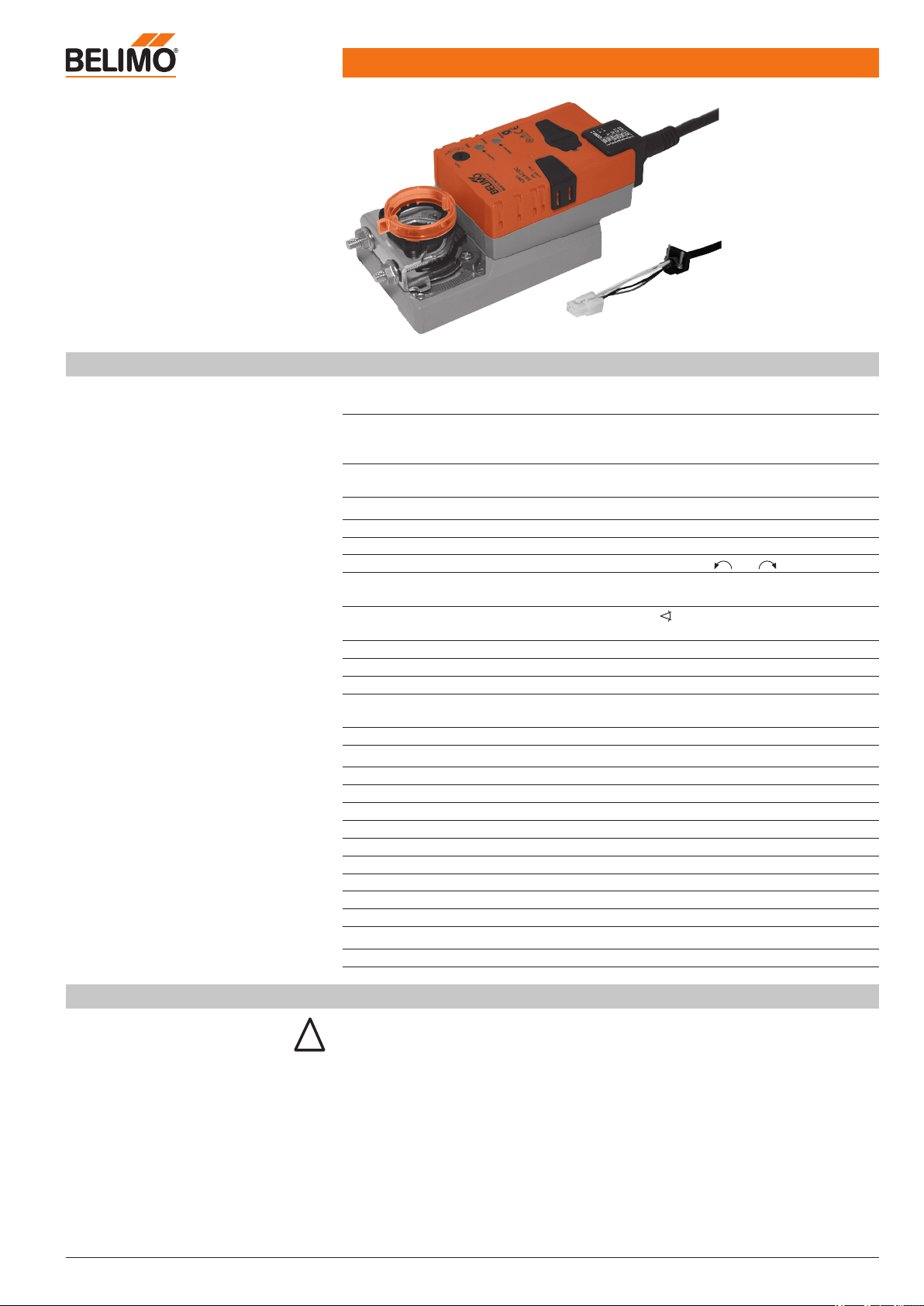
Technical data sheet NM24A-V-ST actuator
www.belimo.eu Product information S4-VRP-M VAV • en • v2.0 • 11.2006 • Subject to changes 23 / 28
Damper actuator
for VRP-M system solution
Technical data
Electrical data
Nominal voltage AC 24 V, 50/60 Hz / DC 24 V
(from VR.. controller)
Power consumption In operation
At rest
For wire sizing
3.5 W @ nominal torque
1.25 W
5.5 VA
Connection 0.5 m cable with 6-pin plug
(compatible with VRP-M)
Functional data
Torque (nominal torque) Min. 10 Nm @ nominal voltage
Uni-rotation ±5%
Direction of rotation Can be selected with 0 / 1 switch
Direction of motion at Y = 2 V In switch position 0 or 1
Manual override Disengaging the gearing latch by means
of a pushbutton, self-resetting
Angle of rotation
Max. 95° , can be limited at both ends
with adjustable mechanical end stops
Running time 150 s
Sound power level Max. 35 dB (A)
Position indication Mechanical, plug-on
Adaptation Adaptation of the control range
to the damper angle of rotation
Display LED display for 24 V supply and states
Safety
Protection class III Safety extra-low voltage
Degree of protection IP54 in all mounting positions
EMC CE according to 89/336/EEC
Mode of operation Type 1 (in acc. with EN 60730-1)
Rated impulse voltage 0.8 kV (in acc. with EN 60730-1)
Control pollution degree 3 (in acc. with EN 60730-1)
Ambient temperature range –30 ... +50°C
Non-operating temperature range –40 ... +80°C
Ambient humidity range 95% RH, non-condensating (EN 60730-1)
Maintenance Maintenance-free
Dimensions/weight
Dimensions See «Dimensions» on page 25
Weight Approx. 710 g
Safety notes
!
• The damper actuator is not allowed to be used outside the specified field of application,
especially in aircraft or in any other airborne means of transport.
• It may only be installed by suitably trained personnel.
All applicable legal or institutional installation regulations must be complied with.
• The device may only be opened at the manufacturer‘s site. It does not contain any parts that
can be replaced or repaired by the user.
• The cable is not allowed to be removed from the unit.
• When the required torque is calculated, the cross section, design and installation site as
well as the air flow conditions must be observed.
Page 24

NM24A-V-ST
Ready-to-connect operating unit
24 / 28 Product information S4-VRP-M VAV • en • v2.0 • 11.2006 • Subject to changes www.belimo.eu
Accessories
Description Data sheet
Electrical accessories
Auxiliary switch S..A.. T2 - S..A..
Feedback potentiometer P..A.. T2 - P..A..
Mechanical accessories
Spindle extension AV6-20 T2 - Z-NM..A..
Product features
Mode of operation
The actuator is controlled with a Belimo VRP-M controller and travels to the position
defined by the control signal.
Simple direct mounting
Simple direct mounting on the damper spindle with a universal spindle clamp, supplied with an
anti-rotation strap to prevent the actuator from rotating.
Manual override
Manual override with self-resetting pushbutton possible (the gear is disengaged for as long as
the button is pressed).
Adjustable angle of rotation
Adjustable angle of rotation with mechanical end stops.
Adaptation
Angle-of-rotation sensing and adaptation of the control range. Triggered by pressing a button on
the actuator, with LEDs for status display.
High functional reliability
The actuator is overload-proof, requires no limit switches and automatically stops when the end
stop is reached.
Electrical installation
The ready-to-connect operating unit is connected to the VRP-M-controller.
Safety notes
(continued)
• The device contains electrical and electronic components and is not allowed to be disposed
of as household refuse. The local and currently valid regulations and requirements must be
observed.
Page 25
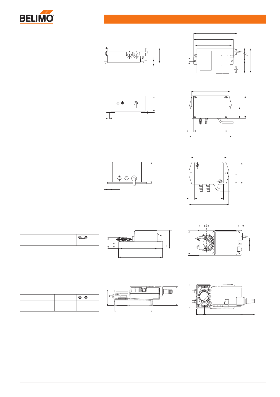
Dimensions
www.belimo.eu Product information S4-VRP-M VAV • en • v2.0 • 11.2006 • Subject to changes 25 / 28
Dimensional drawings
VRP-M controller
Dimensional drawings
VFP-100 sensor
Dimensional drawings
VFP-300 and VFP-600 sensors
Dimensional drawings
NMQB24-SRV-ST actuators
Dimensional drawings
NM24A-V-ST actuators
5
54
4.5
130
140
153
4543
88
5
58
12015
150
13
5
40
80
ø 4.5
49
66
12
90
81
25.5
51
139
22
36.5
58
10
105.6
6.9
26.5
5.2
81
25 121 41
80
124
49
62
Damper spindle Length
Clamp, top min. 40 8 ... 26,7
Clamp, bottom * min. 20 8 ... 20
* Option (accessorie K-NA)
Damper spindle length
min. 38 8 ... 20
Page 26

Notes
26 / 28
Product information S4-VRP-M VAV • en • v2.0 • 11.2006 • Subject to changes
www.belimo.eu
Page 27

Page 28
All inclusive.
Belimo worldwide: www.belimo.com
5 years
Guarantee
Worldwide
present
Complete
assortment from
a single source
Examined
Quality
Short
delivery time
Comprehensive
support
Headquarters Subsidiaries, Representatives and Agencies
BELIMO Holding AG
Brunnenbachstrasse 1
CH-8340 Hinwil
Tel. +41 (0)43 843 61 11
Fax +41 (0)43 843 62 68
[email protected]
www.belimo.com
Agentina
Australia
Bahrain
Belgium
Bosnia-Herzegovina
Brazil
Bulgaria
Canada
Chile
Croatia
Cyprus
Czech Republic
Denmark
Egypt
Estonia
Finland
France
Great Britain
Germany
Greece
Hong Kong
Hungary
Iceland
India
Indonesia
Ireland
Israel
Italy
Japan
Jordan
Kuwait
Latvia
Lebanon
Liechtenstein
Lithuania
Luxembourg
Malaysia
Mexico
Morocco
Netherlands
New Zealand
Norway
Oman
Pakistan
People’s Republic of China
Philippines
Poland
Portugal
Qatar
Republic of Korea (South Korea)
Rumania
Russia
Saudi Arabia
Singapore
Slovakia
Slovenia
South Africa
Spain
Sweden
Switzerland
Taiwan
Turkey
Ukraine
United Arab Emirates
United States of America
 Loading...