

Page 1
www.belimo.com T5-TRY24-SR • en • v1.1 • 05.2010 • Subject to changes 1 / 2
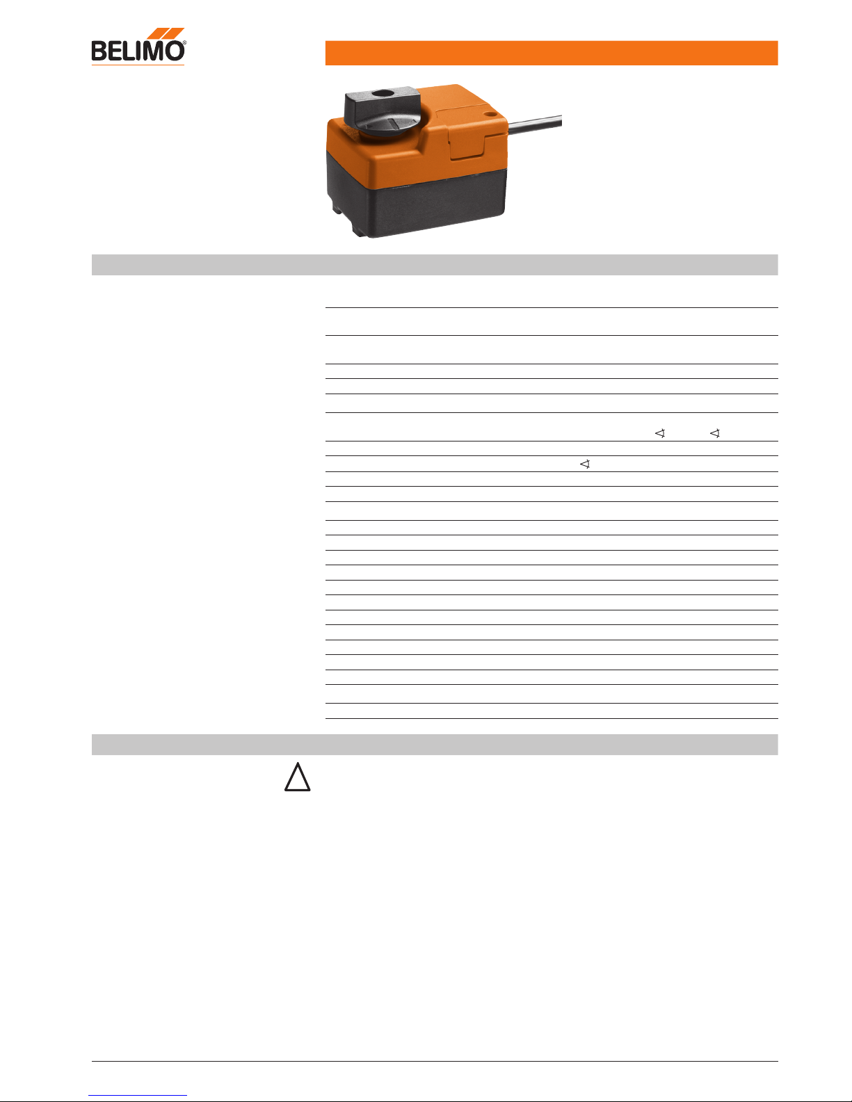
Technical data sheet TRY24-SR
Rotary actuator for 2-way and 3-way
characterised control valves
• Torque 2 Nm
• Nominal voltage AC/DC 24 V
• Control modulating DC 0 ... 10 V
Technical data
Electrical data
Nominal voltage AC 24 V, 50/60 Hz
DC 24 V
Nominal voltage range AC 19.2 ... 28.8 V
DC 21.6 ... 28.8 V
Power consumption Operation
For wire sizing
0.5 W @ nominal torque
1 VA
Connection Cable 1 m, 3 x 0.75 mm2
Parallel operation Yes (note performance data for supply!)
Functional data
Torque (nominal torque) Min. 2 Nm @ nominal voltage
Control Control signal Y
Operating range
DC 0 ... 10 V, Input impedance 100 k�
DC 2 ... 10 V for 0 ... 100% (0 ... 90° )
Manual override Temporary gear latch
Running time
35 s / 90°
Noise level Max. 45 dB (A)
Position indication Mechanical
Safety
Protection class III Extra-low voltage
Degree of protection IP40
EMC CE acc. to 89/336/EEC
Mode of operation Type 1 (acc. to EN 60730-1)
Rated impulse voltage 0.8 kV (acc. to EN 60730-1)
Control pollution degree 3 (acc. to EN 60730-1)
Ambient temperature –7 ... +50°C
Medium temperature +5 ... +100°C (in ball valve)
Medium temperature with R4..DK ball valve +5 ... +130°C (in ball valve)
Non-operating temperature –40 ... +80°C
Ambient humidity range 95% r.h., non-condensating (EN 60730-1)
Maintenance Maintenance-free
Dimensions / Weight
Dimensions See «Dimensions» on page 2
Weight Approx. 400 g (without ball valve)
Safety notes
!
• The actuator has been designed for use in stationary heating, ventilation and air conditioning
systems and is not allowed to be used outside the specified field of application, especially in
aircraft or in any other airborne means of transport.
• It may only be installed by suitably trained personnel.
Any legal regulations or regulations issued by authorities must be observed during
assembly.
• The device may only be opened at the manufacturer's site. It does not contain any parts that
can be replaced or repaired by the user.
• The device contains electrical and electronic components and is not allowed to be disposed
of as household refuse. All locally valid regulations and requirements must be observed.
• The switch for changing the direction of rotation may only be operated by trained personnel.
The direction of rotation may not be changed with frost protection circuit.
.
.
.
.
.
.
.
.
Page 2
TRY24-SR
Rotary actuator AC/DC 24 V, 2 Nm
2 / 2 T5-TRY24-SR • en • v1.1 • 05.2010 • Subject to changes www.belimo.com
Product features
Mode of operation
The actuator is controlled with a standard modulating signal of DC 0 ... 10 V and travels to the
position dened by the control signal.
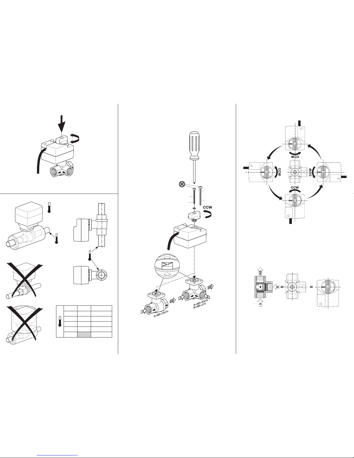
Simple direct mounting
Straightforward direct mounting on the ball valve with only one screw. The mounting position in
relation to the ball valve can be selected in 90° steps.
Manual override
Manual operation with lever possible (the gearing is disengaged for as long as the self-resetting
lever is pressed).
High functional reliability
The actuator is overload-proof and automatically stops when the end stop is reached.
The actuator switches off for seven seconds in the case of blocking, then attempts to restart. If
the blocked condition persists, the actuator attempts to restart once every two minutes a total of
15 times and subsequently once every two hours.
Combination valve actuators
Refer to the valve documentation for suitable valves, their permitted media temperatures and
closing pressures.
Further documentation
• The complete range of water solutions
• Data sheets for ball valves
• Installation instructions for actuators or ball valves, respectively
• Notes for project planning (hydraulic characteristic curves and circuits, installation regulations,
commissioning, maintenance, etc.)
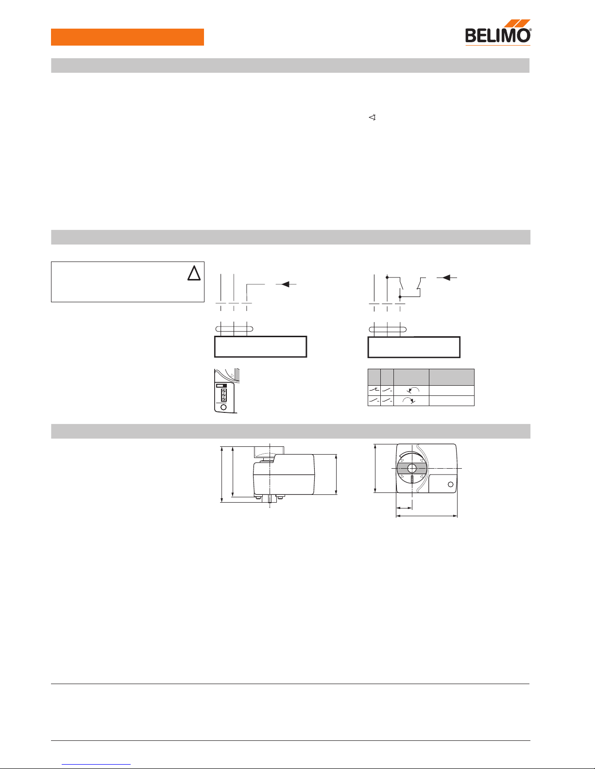
Electrical installation
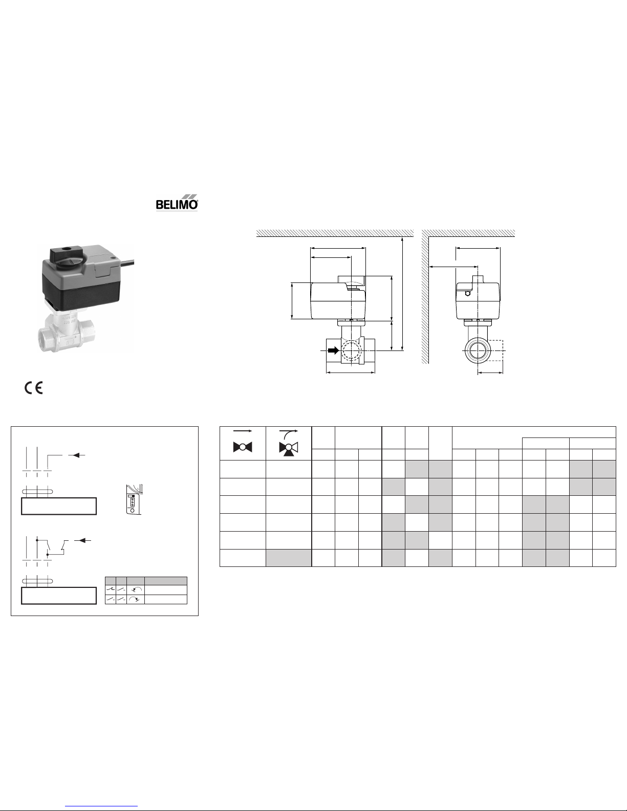
Wiring diagrams Standard Override control (frost protection circuit)
Y
1
32
DC 0 ... 10 V
– +
T
~
Y
Y
1
32
DC 0 ... 10 V
– +
T
~
Y
c
d
R
1 2 3
c d
Rotary
actuator Rotary valve
1
A – AB = 100%
0
A – AB = 0%
Dimensions [mm]
Dimensional drawings
69
78
55
22
84
67
Control of controller
Direction of rotation R
(standard) with switch
position on the right
Control of controller
Information
• Connect via safety isolation transformer.
• Parallel connection of other actuators possible.
Note performance data for supply.
!
.
.
.
.
.
.
.
.
Page 3
70632-00001.C
67
min. Y
62
84
55
69
H
M
L
min. X
°C DN Rp G PN mm
TRD24-SR(-T) TR(Y)24-SR(-T)
max. mm
„ „ „
L H M X Y X Y
R2..K R3..K
100 10 ³/₈ ³/₈ 52 35 28 174 75
R4..K R5..K
100 10 ³/₈ ³/₄ 69 31.5 34 171 75
R2.. R3..
100 15 ¹/₂ ¹/₂ 67 45 39 184 75
R4.. R5..
100 15 ¹/₂ 1 74 44 38 183 75
R6..R R7..R
100 15 ¹/₂ 6 101.5 45 73 184 80
R4..DK
130 10 ³/₈ ³/₄ 65 38 13 177 75
TRD24-SR (-T)
TR24-SR (-T)
TRY24-SR
Y
1
32
DC 0 ... 10 V
– +
T
~
Y
AC 24 V
DC 24 V
R
1 2 3
Y
1
32
DC 0 ... 10 V
– +
T
~
Y
c
d
AC 24 V
DC 24 V
c d
1
A – AB = 100%
0
A – AB = 0%
Page 4
Nr. 1
max. 0.8 Nm
max. 50°C
M4
M5
R2..K R3..K
max. 100°C
R4..K R5..K
max. 100°C
R2.. R3..
max. 100°C
R4.. R5..
max. 100°C
R6..R R7..R
max. 100°C
R4..DK
max. 130°C
R..(R)
R..(D)K
 Loading...