

Belimo TRANE TLF, TRANE TGM, TRANE TNM, TRANE TAM, TRANE TAF24 Technical Documentation Manual
...Page 1

Technical Documentation
Damper Actuators and Accessories
Effective October 2006
Table of Contents
Actuator Product Range....................2
Features and Benefits .......................4
Sizing & Selecting Actuators .............5
Control Signal Overview....................6
Actuator Nomenclature......................8
Actuators
TAF Series
(133 in-lb spring return).........12
TNF Series (60 in-lb spring return)..........28
TLF Series (35 in-lb spring return) ..........42
TTF Series (18 in-lb spring return)..........58
TGM Series (360 in-lb)........................74
TAM Series (180 in-lb) ........................80
TNM Series (90 in-lb) .........................86
TLM Series
(45 in-lb)..........................92
Accessories
Mechanical Accessories................110
Electronic Accessories ..................132
Wiring Guide ................................143
Trane Technology Center, LaCrosse, Wisconsin
Solutions Provided by
®
Page 2
2
I20683 - Subject to change.
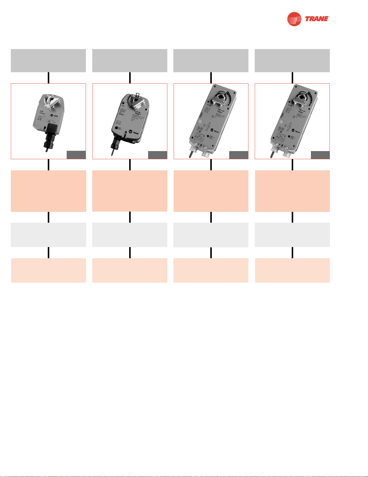
Actuator Product Range
Spring Return
TTF Series
18 in-lb [2 Nm]
Approx. 4.5 sq. ft.
TNF Series
60 in-lb [7 Nm]
Approx. 15 sq. ft.
TAF Series
133 in-lb [15 Nm]
Approx. 33 sq. ft.
Control:
On/Off
Floating Point
2-10 VDC
4-20 mA w/500Ω resistor
Power Supply:
24 VAC/DC
Power Supply:
24 VAC/DC
Options:
Built-In Auxiliary Switch
Options:
Built-In Auxiliary Switch
Options:
Built-In Auxiliary Switch
Options:
Built-In Auxiliary Switch
Power Supply:
24 VAC/DC
Power Supply:
24 VAC/DC
TLF Series
35 in-lb [4 Nm]
Approx. 8 sq. ft.
Control:
On/Off
Floating Point
2-10 VDC
4-20 mA w/500Ω resistor
Control:
On/Off
Floating Point
2-10 VDC
4-20 mA w/500Ω resistor
Control:
On/Off
Floating Point
2-10 VDC
4-20 mA w/500Ω resistor
Pg 42
Pg. 58
Pg 12
Pg 28
Page 3
3
I20683 - Subject to change.
Actuator Product Range
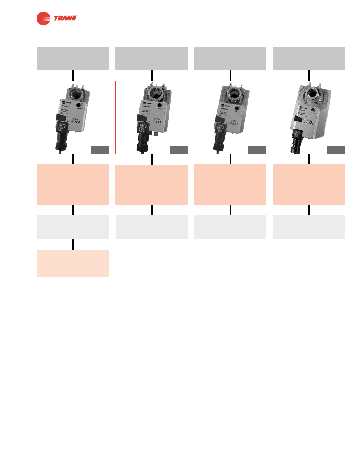
Non-Spring Return
TLM Series
45 in-lb [5 Nm]
Approx. 11 sq. ft.
TAM Series
180 in-lb [20 Nm]
Approx. 45 sq. ft.
TGM Series
360 in-lb [40 Nm]
Approx. 90 sq. ft.
TNM Series
90 in-lb [10 Nm]
Approx. 22 sq. ft.
Control:
Floating Point
2-10 VDC
4-20 mA w/500Ω resistor
Power Supply:
24 VAC/DC
Power Supply:
24 VAC/DC
Basic Options:
Terminal Strip
Bulk Packs
Power Supply:
24 VAC/DC
Power Supply:
24 VAC/DC
Control:
Floating Point
2-10 VDC
4-20 mA w/500Ω resistor
Control:
Floating Point
2-10 VDC
4-20 mA w/500Ω resistor
Control:
Floating Point
2-10 VDC
4-20 mA w/500Ω resistor
Pg 74
Pg 92
Pg 86
Pg 80
Page 4
4
I20683 - Subject to change.
Why Belimo?
A CLOSER LOOK…
Features and Benefits
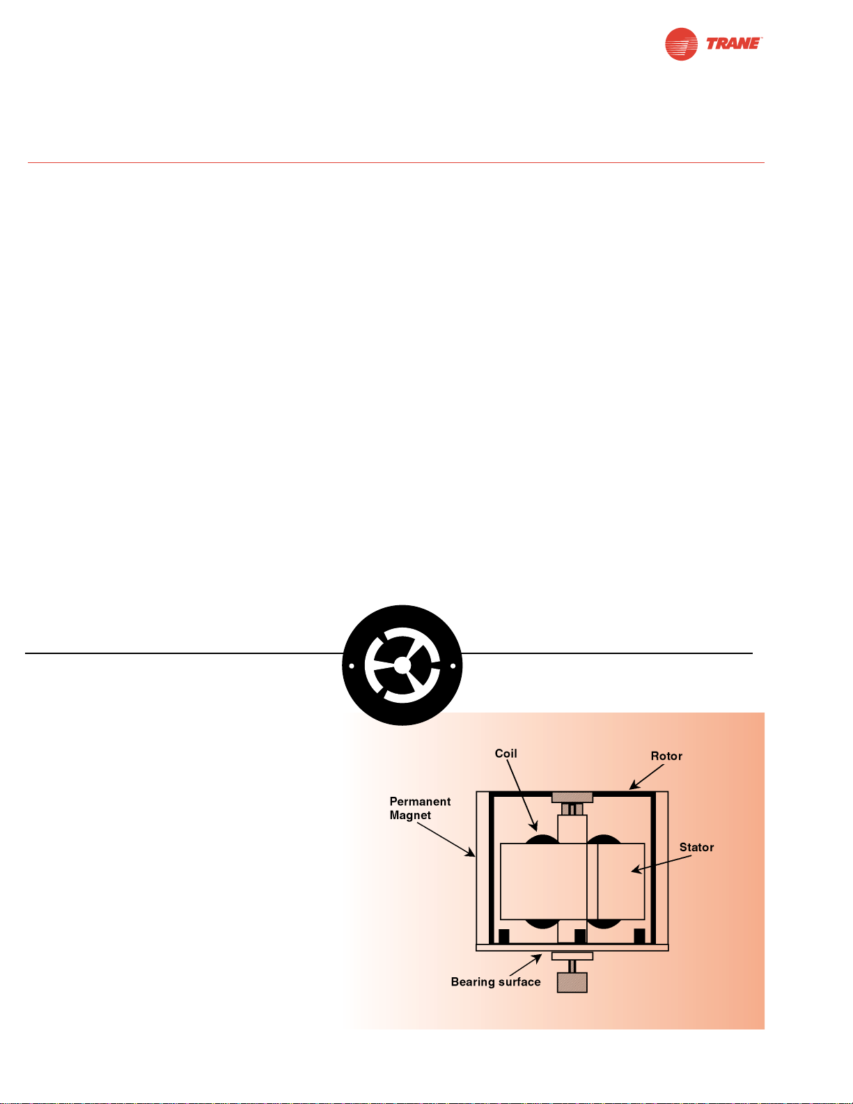
Brushless DC Motor Technology
Belimo new generation actuators all employ
state-of-the-art halomo sensorless, brushless DC
motor technology. The halomo technology was
developed exclusively by Belimo’s Technology
division and enables Trane to offer the high quality
of brushless DC motor technology inside all actuator
models in the new generation.
With the increase in product lifespan and quality
the TLM series creates a new level of expectation
for actuators installed in VAV applications.
● Only ONE moving part!
● No brushes to wear out
● Position feedback is generated by ASIC
● Overload proof; uses integrated end stop filtering
● Running noise is reduced to absolute minimum
©
H
A
L
O
M
O
B
r
u
s
h
l
e
s
s
D
C
M
o
t
o
r
Damper Actuators
● Extensive product range.
● Specific retrofit offerings.
● Small dimensions in relation to torque.
● Microprocessor-controlled Brushless
DC motor increases actuator life span
and reliability & provides constant
running time (most actuators).
● Cut labor costs with simple direct
coupling.
● Check damper position easily with
clear position indication.
● Overload-proof throughout rotation.
● Temporary restrictions in damper
movement will not change actuator
operation. Actuator returns to normal
operation when restriction is remove.
● Built-in or add-on mechanical stops to
adjust angle of rotation.
● Built-in auxiliary switch is easy to use,
offers feedback or signal for additional
device (-S models).
● Need to change control direction?
Do it easily with a simple switch on
actuator housing.
● Rugged housings withstand rough
handling in the mechanical room.
● Automatically compensates for
damper seal wear, ensuring tight
close off.
Spring Return
● True mechanical spring return – the
most reliable fail-safe.
● Reverse mount for clockwise or
counterclockwise fail-safe.
● Manual override crank speeds
installation (TAF Series).
● 3 ft. appliance cable and conduit
connector eases installation.
Non-Spring Return
● Increased torque output by up to 28%
● More mounting flexibility –
TLM accepts 3/4" dia. shafts,
TNM, TAM & TGM mounts to 1.05"
dia. jackshafts.
● New optional external auxiliary
switch(es) or position feedback
potentiometer modules – same
modules for all non-spring return
actuators!
● Manual override push button.
● Compatible to discontinued models.
Page 5
5
I20683 - Subject to change.
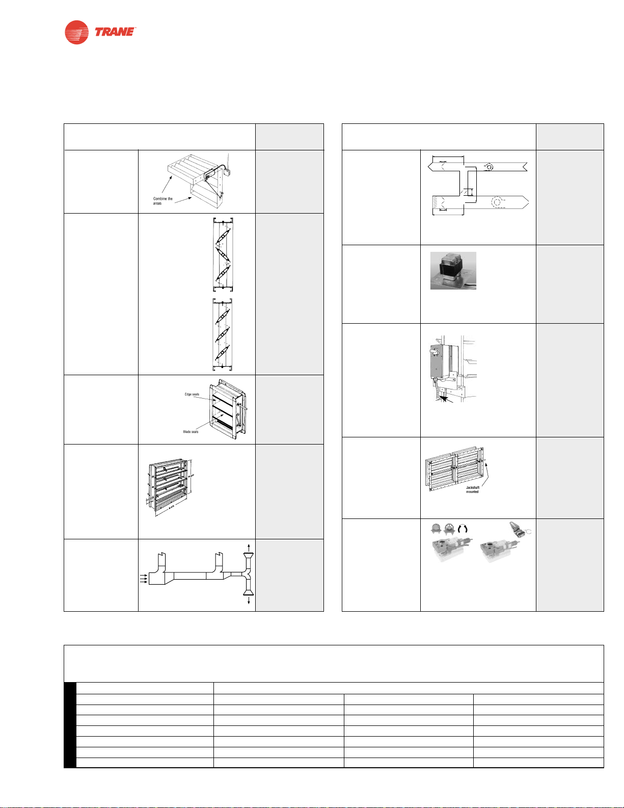
The “10 questions” method for sizing and selection is recommended as the best method for your actuation requirements.
Use the ‘Application Data’ column in this chart as a worksheet
to help in the selection process. This data, along with the
‘Actuator Product Range’ charts on pages 2 and 3, allow for the
best selection of a Trane actuator.
Damper with square shape: ft2= h x w /144; (h= high, w= width)
Damper Area (8 ft2) x Rated Torque Loading of Damper (4 in-lb/ft2) = Total in-lb Required (32 in-lb) TLF/TLM 35 in-lb
Torque Loading in-lb/ft
2
< 1000 FPM FPM FPM
Damper Blade 2 inch water column 1000-2500 2500-3500
Parallel blade/edge seals 7 10.5 14
Opposed blade/edge seals 5 7.5 10
Parallel blade/no edge seals 4 6 8
Opposed blade/no edge seals 3 4.5 6
Round 10 14 20
Sizing and Selecting Actuators
This will impact
the proper
selection as the
seals add resistance requiring
more torque.
If this information is not
available refer
to the “typical
damper
requirements”
chart.
Systems above 1,000 FPM
require additional actuator torque
FAN
FAN
E
OA
R
SA
A = MIXING PLENUM
∆P
T
∆
P
D
∆PD
∆PD
∆PT
∆PT
A
B
OA
Consider the application. Is the actuator/damper exposed to outside air?
use spring return.
• Two position
• Floating point
• Modulating
• Sequencing
• “Non-standard”
voltage signals
This will be a critical component to the
damper selection of an actuator.
Controller
If unknown use
a worst case scenario, parallel blade
with seals.
L” x W” = Total sq
inches/144 = total
sq feet
Typical Damper Requirements and Sizing
SQUARE
What is the
total area of
the damper?
Opposed blade
or parallel
blade control
construction?
Are there
blade and
edge seals on
the damper?
For the
damper in
question,
what does the
manufacturer
specify as the
torque rating?
What is the air
velocity, static
pressure or
design CFM?
Is fail-safe
required?
What is
the supply
voltage to
the actuator?
• 24 VAC/DC
What is
the control
signal to the
actuator?
Can you direct
couple to a
damper shaft?
Are there
additional
accessories
required?
___________
sq. ft.
❑ Opposed
Blade
❑ Parallel
Blade
❑ YES
❑ NO
___________
in-lb/sq. ft.
_______W.G.
_______CFM
_______FPM
❑ YES
❑ NO
❑ 24 VAC
❑ On/Off
❑ Floating
Point
❑ 2-10 VDC
❑ 4-20 mA
❑ YES
❑ NO, see
accessories
page
❑ NO
❑ YES, see
accessories
section or
actuator
series for
details
Opposed Blade
w/o seals 3 in-lb/sq feet
Opposed Blade
w/ seals 5 in-lb/sq feet
Parallel Blade
w/o seals 4 in-lb/sq feet
Parallel Blade
w/ seals 7 in-lb/sq feet
Do you need
a step down
transformer?
If replacing an oil
immersed gear
train actuator. Is
the transformer in the defective actuator? You may need to purchase one.
Direct coupling has
become the
industry standard. Some
retrofit applications do not
allow direct
coupling.
Some applications require the additions of
an auxiliary switch for proof of position. Or
a retrofit application may require an additional mounting bracket and linkage kit.
You must identify these needs prior to
leaving the job site or ordering products.
KH-AF US
KH-AF-1 US
K4-2 US
PA…
SA…
Application
Criteria Data
1
2
3
4
5
Application
Criteria Data
6
7
8
9
10
Page 6

6
I20683 - Subject to change.
Control Signal Overview
Trane actuators are compatible with many control inputs. There
are many signals to select from with today’s controllers.
What does ‘on-off’, ‘open-close’, ‘3-point’, ‘tri state’, ‘floating point’,
‘proportional modulation’, mean?
Trane will help you understand more on this control signal
jungle with a quick overview:
On-Off or Open-Close: The actuator is able to drive either to
its full open position, or to its full closed position. The same
indication is used for Spring return type actuators. However the
actuator will drive to its full open position and spring return to its
zero position. This can also be reversed.
3-Point, Tri-state, Floating Point: The actuator has both clockwise (CW) and counter-clockwise (CCW) control inputs. One
drives the actuator to its open, the other to its close position. If
there is no signal (Null point) on either input the actuator simply
stays in its last position.
Proportional Control: The Actuator drives proportional to its
control input and modulates through-out its angle of rotation. This
control type is usually a variation of VDC. Common values are:
0-10 VDC 2-10 VDC
It is common to also have a 0-20 mA output from a controller.
This can be very easily converted to 0-10VDC or 2-10 VDC
with a 500Ω resistor.
Page 7

Notes/Work Pad
7
I20683 - Subject to change.
Page 8

8
I20683 - Subject to change.
TORQUE STANDARD POWER SUPPLY CONTROL
TAF 133 in-lb 24 24 VAC/DC Blank On/Off
TNF 60 in-lb 3 Floating Pt
TLF 35 in-lb SR 2 to 10 VDC
TTF 18 in-lb
Actuator Nomenclature
Spring Return
Spring Return Nomenclature
Example
TAF24-SR
Torque 133 in-lb
Actuator Type Standard
Power Supply 24 VAC/DC
Control Signal 2 to 10 VDC
Auxiliary Switch Not applicable
Clamp Size 1.05" standard clamp
Electrical Connection 3 ft, 18 GA appliance cable
TAF 24 -SR
Page 9
9
I20683 - Subject to change.
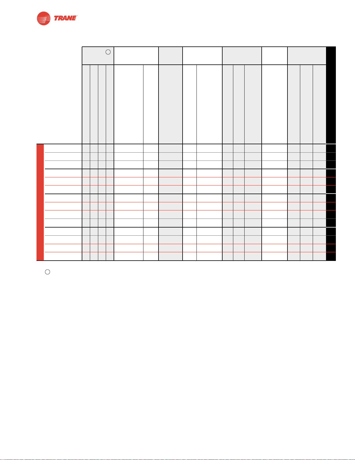
Spring Return Actuator Product Range
Actuator Application Chart
TAF24 ● 150 <20 ● 10 5 (1.5) ● 14
TAF24-S ● 150 <20 ● 10 5 (1.5) ●●14
TAF24-SR ● 150 <20 ● 10 6 (2) ●● 16
TNF24 ● <75 <60 ● 8 5 (2.6) ● 30
TNF24-S ● <75 <60 ● 8 5 (2.6) ●●30
TNF24-SR ● 150 <60 ● 6 3 (1) ●● 32
TLF24 ● < 40 to 75 <25
♦
● 7 5 (2.5) ● 44
TLF24-S ● < 40 to 75 <25
♦
● 7 5 (2.5) ●●44
TLF24-SR ● 150 <25
♦
● 5 2.5 (1) ●● 48
TLF24-3 ● 150 <25
♦
● 5 2.5 (1) ● 46
TTF24 ● < 75 <25
♦
● 4 2 (1.3) ● 60
TTF24-S ● < 75 <25
♦
● 4 2 (1.3) ●●60
TTF24-SR ● 95 <25
♦
● 3 2 (1) ● 64
TTF24-3
● 95 <25
♦
● 5 2.5 (1) ● 62
♦
<60 seconds @-22°F [-30°C]
For complete guide to sizing actuators see page 5.
18 in-lb [2 Nm], Apprx. 4.5 sq. ft.
35 in-lb [4 Nm], Apprx. 8 sq. ft.
60 in-lb [7 Nm], Apprx. 15 sq. ft.
133 in-lb [15 Nm], Apprx. 33 sq. ft.
Motor Drive
Spring Return
24 VAC +/- 20%, VDC +/- 15%
VA rating
Wattage running (holding)
On/Off
Floating Point
2-10 VDC (Default)
4-20 mA* (w/500 ohm resistor)
2-10 VDC (Default)
1 SPDT, 3A (0.5A inductive) @250 V
1 SPDT, 6A (1.5A inductive) @250 V
2 SPDT, 7A (2.5A inductive) @250 V
See Page Number
Running Power Power Control Position Auxiliary
Time Supply Consumption Input Feedback Switches
Torque
(based on 4 in-
lb per sq. ft)
Spring Return
Airside Products
B
B
Page 10

10
I20683 - Subject to change.
Actuator Nomenclature
Non-Spring Return
Non-Spring Return Nomenclature
Example
TLMB24-3-T
Torque 45 in-lb
Actuator Type Basic
Power Supply 24 VAC/DC
Control Signal On/Off, Floating Pt.
Auxiliary Switch Add-on
Clamp Size 5/8" LM standard
Electrical Connection Terminal strip
Terminal Screw Strip
TLM B 24 -3 -T
Actuator Family
Standard (95° Rotation) ACTUATOR TYPE POWER SUPPLY CONTROL
TGM 360 in-lb B Basic 24 24 VAC/DC 3 On/Off, Floating
Point
TAM 180 in-lb
SR 2 to 10 VDC
TNM 90 in-lb
TLM 45 in-lb
Page 11
11
I20683 - Subject to change.
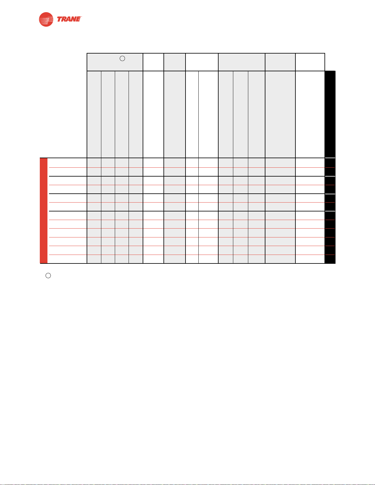
Non-Spring Return Actuator Product Range
Actuator Application Chart
Torque Running Power Power Control Position Auxiliary
Time Supply Consumption Input Feedback Switches
(based on 4 in-lb per sq. ft)
TGMB24-3† ● 150 ● 7 4.5 (2) ●● ● 76
TGMB24-SR† ● 150 ● 7 4.5 (2) ●● ●78
TAMB24-3 ● 95 ● 6 2.5 (0.5) ●● ● 82
TAMB24-SR ● 95 ● 5 2.5 (0.5) ●● ●84
TNMB24-3 ● 95 ● 4 2.5 (0.5) ●● ● 88
TNMB24-SR ● 95 ● 4 2.5 (0.5) ●● ●90
TLMB24-3 ● 95 ● 2 1.5 (0.2) ●● ● 94
TLMB24-3-T ● 95 ● 2 1.5 (0.2) ●● ● 94
TLMB24-3-T.1 ● 95 ● 2 1.5 (0.2) ●● ● 94
TLMB24-SR ● 95 ● 3 1.5 (0.5) ●● ●96
TLMB24-SR-T ● 95 ● 3 1.5 (0.5) ●●96
TLMB24-SR-T.1 ● 95 ● 3 1.5 (0.5) ●●96
†For dual mounting on a single shaft the total sizing torque must not exceed 640 in-lbs (-3 and -SR wired in parallel).
For complete guide to sizing actuators see page 5.
45 in-lb [5 Nm], Apprx. 11 sq. ft.
90 in-lb [10 Nm], Apprx. 22 sq. ft.
180 in-lb [20 Nm], Apprx. 45 sq. ft.
360 in-lb [40 Nm], Apprx. 90 sq. ft.
Motor Drive
24 VAC +/- 20%, VDC +/- 15%
VA Rating
Wattage Running (holding)
On/Off
Floating Point
2-10 VDC
4-20 mA (w/500Ω resistor)
2-10 VDC
Add-on
See Page Number
Non-Spring Return
Airside Products
B
B
Page 12
12
I20683 - Subject to change.
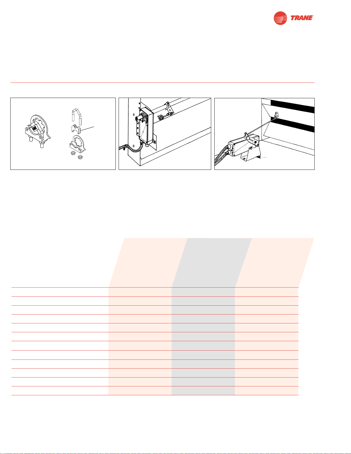
TAF Series Spring Return Direct Coupled Actuator
Applications
Minimum 133 in-lb Torque
● For damper areas up to 35 sq-ft*
(For lower torque, see TNF, TLF, or TTF series)
ZG106 or
ZG 107
bracket
Mount directly to 1.05” jackshafts.
New standard clamp fits standard 1/2”
shafts to 1.05” jackshafts.
Linkage solutions are available when direct coupling is
not possible.
Remove
for 3/4”
to 1.05”
shafts
Torque: 133 in-lb ●●●
Power supply : 24 VAC/DC ●●●
Control signal: on-off ●●●
proportional: 2 to 10 VDC ●
Feedback signal: 2 to 10 VDC ●
Running time motor: 150 sec constant ●●●
spring: <20 sec ●●●
Brushless DC Motor ●●●
External direction of rotation switch ●
Manual override ●●●
Appliance rated cable, 18 GA ●●●
Built-in auxiliary switch 2 SPDT ●
Installation instructions......(p. 18–23) General wiring ..............(p. 25) Startup and checkout (p. 26)
Electrical operation............(p. 24)
*Based on 4 in-lb/ft2damper torque loading. Parallel blade. No edge seals.
TAF Series – AT A Glance
TAF24 (p. 14)
TAF24-S (p. 14)
TAF24-SR (p. 16)
Page 13
13
I20683 - Subject to change.
TAF
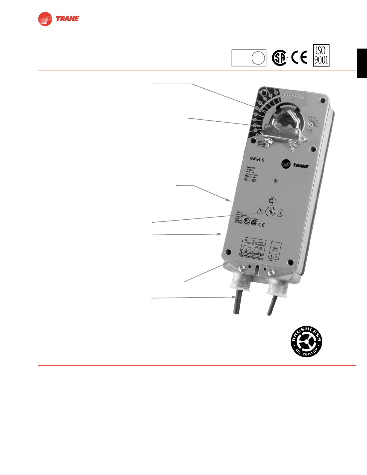
A CLOSER LOOK…
TAF Series Spring Return Direct Coupled Actuator
● Cut labor costs with simple direct coupling.
● True mechanical spring return – the most reliable fail-safe.
● Reverse mount for clockwise or counterclockwise fail-safe.
● Check damper position easily with clear position indicator.
● Overload-proof throughout rotation
● Temporary restrictions in damper movement will not change
actuator operation. Actuator returns to normal operation when
restriction is removed. (modulating actuators)
● Easy mechanical stop to adjust angle of rotation
(add ZDB-AF2 accessory).
● By eliminating internal condensation Golden Point
breather membrane optimizes performance in harsh
airstream environments.
● Built-in auxiliary switch is easy to use, offers feedback
or signal for additional device. (-S models)
● Manual override crank speeds installation
● Need to change control direction?
Do it easily with a simple switch. (modulating actuators)
● Microprocessor-controlled brushless DC motor increases
actuator life span and reliability, provides constant running
time (modulating actuators).
● Rugged metal housing withstands rough handling in the
mechanical room.
● 3 ft. appliance cable and conduit connector
eases installation.
● Double insulated – no need for separate safety ground.
(-S models)
● Automatically compensates for damper seal wear, ensuring tight
close-off.
The T rane Difference
● Low Installation and Life-Cycle Cost.
Easy installation. Accuracy and repeatability.
Low power consumption. No maintenance.
●
Long Service Life.
Components tested before assembly. Every product tested before shipment.
30+ years direct coupled actuator design.
©
LISTED
94D5
TEMP. IND &
REG. EQUIP.
U
L
Page 14
I20683 - Subject to change.
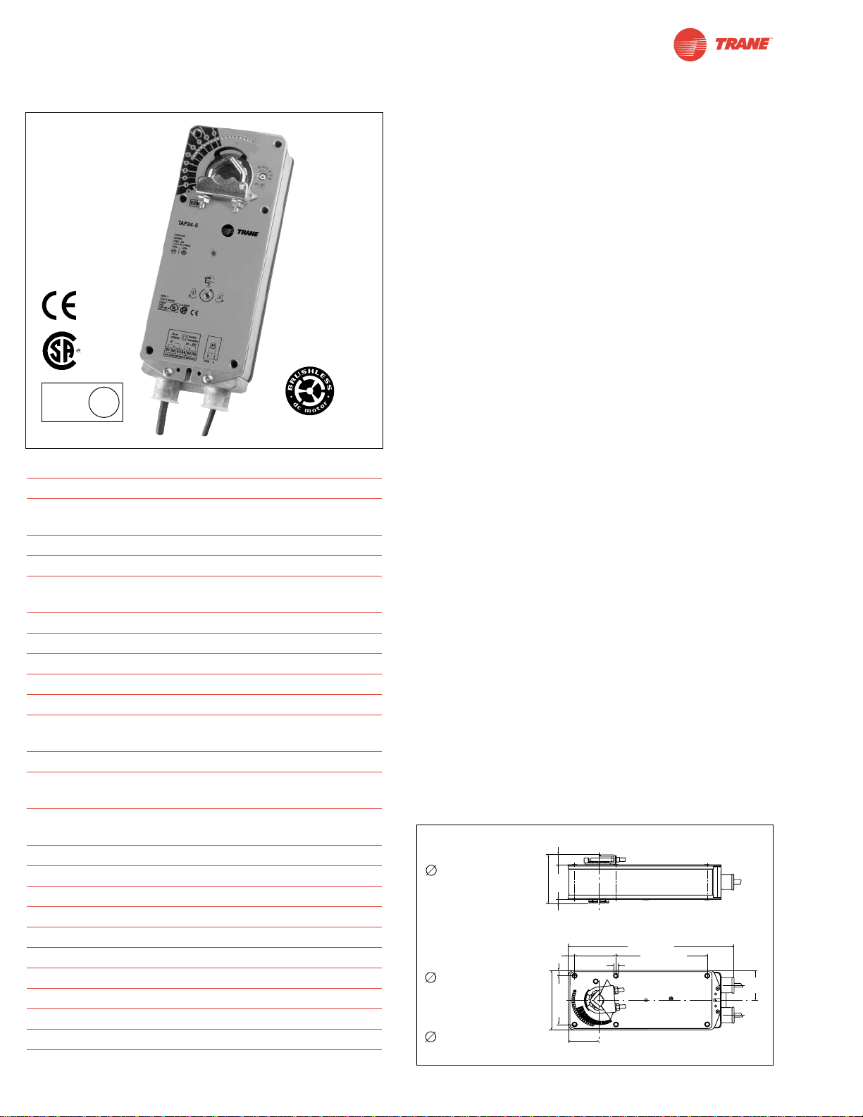
TAF24 (-S)
On-off, Spring Return Fail-Safe, 24 V
Torque min. 133 in-lb, for control of air dampers
Application
For on-off, fail-safe control of dampers in HVAC systems.
Actuator sizing should be done in accordance with the damper
manufacturer’s specifications. Control is on-off from an
auxiliary contact, or a manual switch.
The actuator is mounted directly to a damper shaft up to 1.05”
in diameter by means of its universal clamp. A crankarm and
several mounting brackets are available for applications where
the actuator cannot be direct coupled to the damper shaft.
Operation
The TAF series actuators provide true spring return operation
for reliable fail-safe application and positive close off on air tight
dampers. The spring return system provides consistent torque
to the damper with, and without, power applied to the actuator.
The TAF series provide 95° of rotation and are provided with a
graduated position indicator showing 0° to 95°. The TAF has a
unique manual positioning mechanism which allows the setting of any damper position within its 95° of rotation. The TAF
series actuators are shipped at +5° (5° from full fail-safe) to
provide automatic compression against damper gaskets for
tight shut-off. When power is applied to the TAF series, the
manual mechanism is released. The actuators will now try to
close against the 0° position during its normal control operations. The manual override can also be released physically by
the use of a crank supplied with the actuator.
The TAF uses a brushless DC motor which is controlled by an
Application Specific Integrated Circuit (ASIC). The ASIC monitors and controls the actuator’s rotation and provides a digital
rotation sensing function to prevent damage to the actuator in
a stall condition. The actuator may be stalled anywhere in its
normal rotation without the need of mechanical end switches.
The TAF24-S version is provided with 2 built in auxiliary
switches. These SPDT switches are provided for safety interfacing or signaling, for example, for fan start-up. The switching
function at the fail-safe position is fixed at +5°, the other switch
function is adjustable between +25° to +85°.
For all accessories, see pages 110 and 132.
Dimensions
[All numbers in brackets are in millimeters.]
Technical Data TAF24 (-S)
Power supply 24 VAC ± 20% 50/60 Hz
24 VDC ± 10%
Power consumption running: 5 W; holding: 1.5 W
Transformer sizing 10 VA (class 2 power source)
Electrical connection 3 ft, 18 GA appliance cable
1/2” conduit connector
Electrical protection auxiliary switches are double insulated
Overload protection electronic throughout 0° to 95° rotation
Angle of rotation 95°, adjustable 35°to 95° w/ ZDB-AF2
Torque 133 in-lb [15 Nm] constant
Direction of rotation reversible with CW/CCW mounting
Position indication visual indicator, 0° to 95° (0° is spring
return position)
Manual override 3mm hex crank (shipped w/actuator)
Auxiliary switches 2 x SPDT 7A (2.5A) @ 250 VAC,
UL listed
one set at +5°, one adjustable 25°to 85°
Running time 150 sec. constant, independent of
load, spring return < 20 sec
Humidity 5 to 95% RH non-condensing
Ambient temperature -22°F to +122°F [-30°C to +50°C]
Storage temperature -40°F to +176°F [-40°C to +80°C]
Housing NEMA type 2 / IP54
Housing material zinc coated steel
Agency listings UL 873 listed, CSA C22.2 No. 24 certified
Noise level max. 45 dB (A)
Servicing maintenance free
Quality standard ISO 9001
Weight 6.0 lbs (2.7 kg.)
14
D001
©
LISTED
94D5
TEMP. IND &
REG. EQUIP.
U
L
K4-2 US (supplied)
1/2" Centered
(Default)
3/4" Centered
(Field Selectable)
1.05" Centered
(Field Selectable)
K4-1 US (optional)
3/4" to 1.05"
Adjustable
K4 US (optional)
3/8" to 3/4"
Adjustable
0.65" [16.5]
[57]
2.24"
3.25" [82.7]
0.19" [5]
0.39" [10]
0.35" [9]
3.86" [98]
3.15" [80]
1.97"
[50]
2.64"
[67]
10.59" [269]
5.85" [148.5]
0.26" [6.5]
1.93"
[49]
Page 15
15
I20683 - Subject to change.
TAF
TAF24 (-S)
On-off, Spring Return Fail-Safe, 24 V
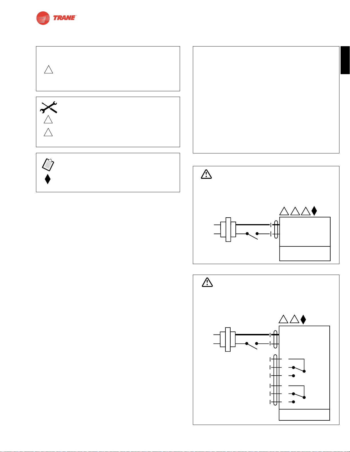
Wiring Diagrams
TAF24 (-S) Typical Specification
On-off spring return damper actuators shall be direct coupled
type which require no crankarm and linkage and be capable
of direct mounting to a jackshaft up to a 1.05” diameter. The
actuators must be designed so that they may be used for
either clockwise or counterclockwise fail-safe operation.
Actuators shall have a manual positioning mechanism
accessible on its cover. Actuators shall use a brushless DC
motor and be protected from overload at all angles of rotation.
Run time shall be constant and independent of torque. If
required, 2 SPDT auxiliary switches shall be provided with
one switch having the capability of being adjustable. Actuators
with switches must be constructed to meet the requirement for
double insulation so an electrical ground connection is not
required to meet agency listings. Actuators are UL listed and
CSA certified, and be manufactured under ISO 9001
International Quality Control Standards. Actuators shall be
as manufactured by Belimo.
1 Common
2 + Hot
2
24 VAC Transformer
TAF24
Line
Volts
35
WARNING
Live Electrical Components!
During installation, testing, servicing and troubleshooting of this product, it maybe
necessary to work with live electrical components. Have a qualified licensed electrician
orother individual who has beenproperly trained in handling live electrical components
perform these tasks. Failure to follow all electrical safety precautions when exposed
to live electrical components could result in death or serious injury.
On-off wiring for TAF24
W450
On-off wiring for TAF24-S
W451
CAUTION
2
3
5
Actuator may also be powered by 24 VDC.
Actuators with plenum rated cable do not have
numbers on wires; use color codes instead.
Actuators with appliance cables use numbers.
Meets cULus or UL and CSA requirements without
the need of an electrical ground connection.
Equipment damage!
Actuators may be connected in parallel. Power consumption and input impedance must be observed.
INSTALLATION NOTES
APPLICATION NOTES
WARNING
Live Electrical Components!
During installation, testing, servicing and troubleshooting of this product, it maybe
necessary to work with live electrical components. Have a qualified licensed electrician
orother individual who has beenproperly trained in handling live electrical components
perform these tasks. Failure to follow all electrical safety precautions when exposed
to live electrical components could result in death or serious injury.
3
24 VAC Transformer
2
Line
Volts
1 Common
2 + Hot
S1
NC
S2
S3
NO
S4
NC
S5
S6
NO
TAF24-S
5°
25° to 85°
Page 16
I20683 - Subject to change.
Torque min. 133 in-lb, for control of air dampers
Application
For proportional modulation of dampers in HVAC systems.
Actuator sizing should be done in accordance with the damper
manufacturer’s specifications.
The actuator is mounted directly to a damper shaft up to 1.05”
in diameter by means of its universal clamp. A crankarm and
several mounting brackets are available for applications where
the actuator cannot be direct coupled to the damper shaft.
The actuator operates in response to a 2 to 10 VDC, with the
addition of a 500Ω resistor, a 4 to 20 mA control input from an
electronic controller or positioner. A 2 to 10 VDC feedback
signal is provided for position indication or master-slave
applications.
Operation
The TAF series actuators provide true spring return operation
for reliable fail-safe application and positive close-off on air tight
dampers. The spring return system provides constant torque to
the damper with, and without, power applied to the actuator.
The TAF series provides 95° of rotation and is provided with a
graduated position indicator showing 0 to 95°. The TAF has a
unique manual positioning mechanism which allows the setting of any damper position within its 95° of rotation. The
actuator is shipped at +5° position (5° from full fail-safe) to
provide automatic compression against damper gaskets for
tight shut-off. When power is applied, the manual mechanism
is released and the actuator drives toward the full fail-safe
position. The actuator will memorize the angle where it stops
rotating and use this point for its zero position for its normal
control operations. The manual override can also be released
physically by the use of a crank supplied with the actuator.
The TAF uses a brushless DC motor which is controlled
by an Application Specific Integrated Circuit (ASIC) and a
microprocessor. The microprocessor provides the intelligence
to the ASIC to provide a constant rotation rate and to know
the actuator’s exact zero position. The ASIC monitors and
controls the brushless DC motor’s rotation and provides a
digital rotation sensing function to prevent damage to the
actuator in a stall condition. The actuator may be stalled
anywhere in its normal rotation without the need of
mechanical end switches.
For all accessories, see pages 110 and 132.
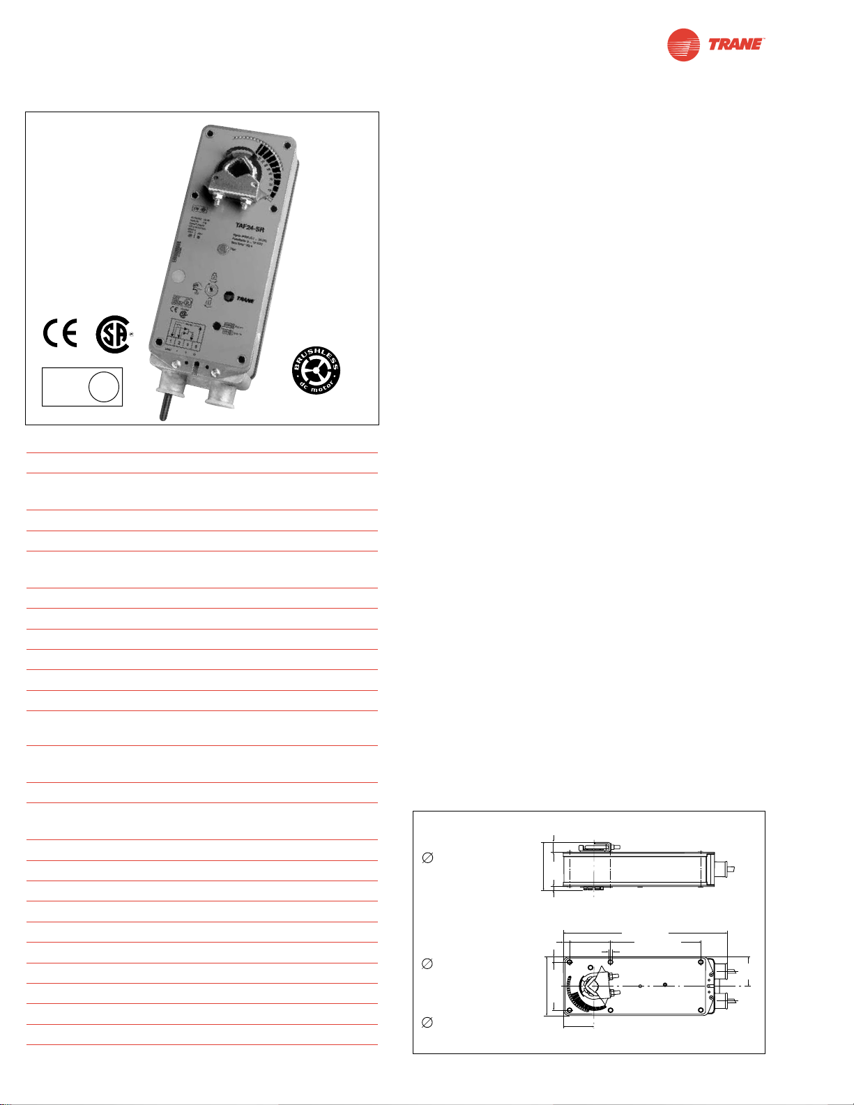
Dimensions
[All numbers in brackets are in millimeters.]
TAF24-SR
Proportional Damper Actuator, Spring Return Fail-Safe, 24 V for 2 to 10 VDC and
4 to 20 mA Control Signal. Output Signal of 2 to 10 VDC for Position Indication
Technical Data TAF24-SR
Power supply 24 VAC ± 20% 50/60 Hz
24 VDC ± 10%
Power consumption running: 6 W ; holding: 2 W
Transformer sizing 10 VA (class 2 power source)
Electrical connection 3 ft, 18 GA appliance cable
1/2” conduit connector
Overload protection electronic throughout 0 to 95° rotation
Operating range Y 2 to 10 VDC, 4 to 20 mA
Input impedance 100kΩ (0.1 mA), 500Ω
Feedback output U 2 to 10 VDC (max. 0.5 mA) for 95°
Angle of rotation mechanically limited to 95°
Torque 133 in-lb [15 Nm] constant
Direction of rotation spring: reversible with cw/ccw mounting
motor: reversible with built-in switch
Position indication visual indicator, 0° to 95° (0° is spring
return position)
Manual override 3mm hex crank (shipped w/actuator)
Running time 150 sec. constant, independent of load,
spring return < 20 sec
Humidity 5 to 95% RH non-condensing
Ambient temperature -22°F to +122°F [-30°C to +50°C]
Storage temperature -40°F to +176°F [-40°C to +80°C]
Housing NEMA type 2 / IP54
Housing material zinc coated metal
Agency listings UL 873 listed, CSA C22.2 No. 24 certified
Noise level max. 45 dB (A)
Servicing maintenance free
Quality standard ISO 9001
Weight 6.0 lbs (2.7 kg.)
LISTED
94D5
TEMP. IND &
REG. EQUIP.
U
L
16
D001
©
K4-2 US (supplied)
1/2" Centered
(Default)
3/4" Centered
(Field Selectable)
1.05" Centered
(Field Selectable)
K4-1 US (optional)
3/4" to 1.05"
Adjustable
K4 US (optional)
3/8" to 3/4"
Adjustable
0.65" [16.5]
[57]
2.24"
3.25" [82.7]
0.19" [5]
0.39" [10]
0.35" [9]
3.86" [98]
3.15" [80]
1.97"
[50]
2.64"
[67]
10.59" [269]
5.85" [148.5]
0.26" [6.5]
1.93"
[49]
Page 17
17
I20683 - Subject to change.
TAF
TAF24-SR
Proportional Damper Actuator, Spring Return Fail-Safe, 24 V for 2 to 10 VDC and
4 to 20 mA Control Signal. Output Signal of 2 to 10 VDC for Position Indication
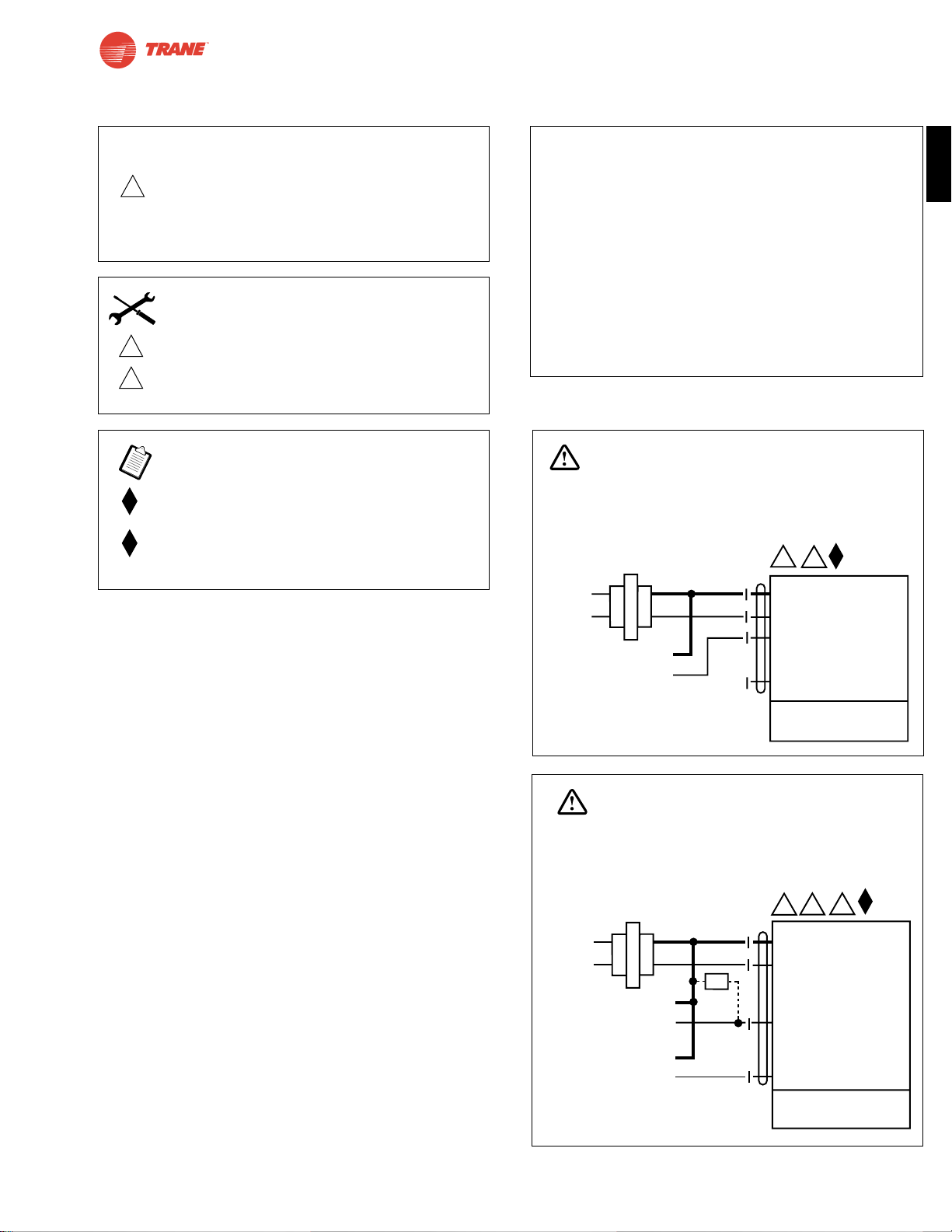
Wiring Diagrams
Control Signal
(+)
2 to 10 VDC
(–)
1 Common
2 + Hot
3 Y Input,
0 to 10V
5 U Output 2 to 10V
2
3
24 VAC Transformer
TAF24-SR
Line
Volts
WARNING
Live Electrical Components!
During installation, testing, servicing and troubleshooting of this product, it maybe
necessary to work with live electrical components. Have a qualified licensed electrician
or other individual who has been properly trained in handling live electrical components
perform these tasks. Failure to follow all electrical safety precautions when exposed
to live electrical components could result in death or serious injury.
1 Common
2 + Hot
3 Y Input, 0 to 10V
5 U Output 2 to 10V
24 VAC Transformer
5
3
2
Control Signal
(+)
4 to 20 mA
(–)
Feedback Signal
(+)
2 to 10 VDC
(–)
Ω
500Ω
Line
Volts
TAF24-SR
WARNING
Live Electrical Components!
During installation, testing, servicing and troubleshooting of this product, it maybe
necessary to work with live electrical components. Have a qualified licensed electrician
or other individual who has been properly trained in handling live electrical components
perform these tasks. Failure to follow all electrical safety precautions when exposed
to live electrical components could result in death or serious injury.
TAF24-SR Typical Specification
Spring return control damper actuators shall be direct coupled type
which require no crankarm and linkage and be capable of direct
mounting to a jackshaft up to a 1.05” diameter. The actuator must
provide proportional damper control in response to a 2 to 10 VDC or,
with the addition of a 500Ω resistor, a 4 to 20 mA control input from
an electronic controller or positioner. The actuators must be
designed so that they may be used for either clockwise or counterclockwise fail-safe operation. Actuators shall have control direction of
rotation switch accessible on its cover. Actuators shall use a brushless
DC motor controlled by a microprocessor and be protected from
overload at all angles of rotation. Run time shall be constant, and
independent of torque. A 2 to 10 VDC feedback signal shall be
provided for position feedback or master-slave applications. Actuators
are UL listed and CSA certified and be manufactured under ISO 9001
International Quality Control Standards. Actuators shall be as
manufactured by Belimo.
W452
CAUTION
2
Equipment damage!
Actuators may be connected in parallel.
Power consumption must be observed and input
impedance must be observed.
3
5
Actuator may also be powered by 24 VDC.
Only connect common to neg. (—) leg of
control circuits
Meets cULus or UL and CSA requirements without
the need of an electrical ground connection.
The ZG-R01 500Ω resistor converts the 4 to 20 mA
control signal to 2 to 10 VDC.
W453
INSTALLATION NOTES
APPLICATION NOTES
Page 18
18
I20683 - Subject to change.
Installation Instructions
Quick-Mount Visual Instructions for Mechanical Installation
IND-AF2 Position Indicator
(optional)
IND-AF2 Position Indicator
(optional)
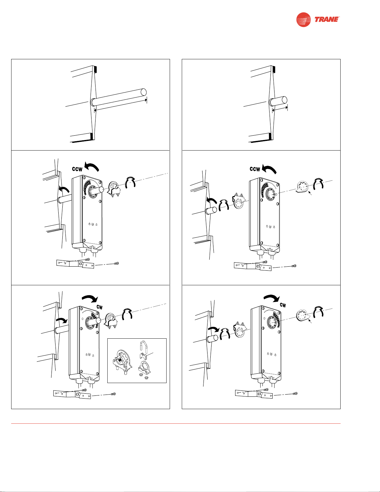
QUICK-MOUNT VISUAL INSTRUCTIONS
1. Rotate the damper to its fail-safe position. If the shaft
rotates counterclockwise, mount the “CCW” side of the actuator out. If it rotates clockwise, mount the actuator with the
“CW” side out.
2. If the universal clamp is not on the correct side of the actuator, move it to the correct side.
3. Slide the actuator onto the shaft and tighten the nuts on the
V-bolt with a 10 mm wrench to 6-8 ft-lb of torque.
4. Slide the anti-rotation strap under the actuator so that it
engages the slot at the base of the actuator. Secure the
strap to the duct work with #8 self-tapping screws.
NOTE: Read the “Standard Mounting” instructions, on the next
page, for more detailed information.
min. 3 1/2"
[90]
min. 3/4"
[20]
Remove
for 3/4”
to 1.05”
shafts
Dimensions (All numbers in brackets are in millimeters.)
Page 19

19
I20683 - Subject to change.
TAF
Installation Instructions
Mechanical Installation
Standard Mounting
Mechanical Operation
The actuator is mounted directly to a damper shaft up to 1.05” in diameter by means of its universal clamp. A crankarm and
several mounting brackets are available for applications where the actuator cannot be direct coupled to the damper shaft. The TAF
series actuators provide true spring return operation for reliable fail-safe application and positive close-off on air tight dampers. The
spring return system provides constant torque to the damper with, and without, power applied to the actuator. The TAF…-S versions
are provided with 2 built-in auxiliary switches. These SPDT switches are provided for safety interfacing or signaling, for example, for
fan start-up. The switching function at the fail-safe position is fixed at +5°, the other switch function is adjustable between +25° to +85°.
Automatic Airtight Dampers/Manual Override
The TAF series provides 95° of rotation and is provided with a graduated position indicator showing 0° to 95°. The TAF has a
unique manual positioning mechanism which allows the setting of any damper position within its 95° of rotation. A pre-tensioned
spring automatically tightens damper when power is applied to the actuator, compensating for damper seal deterioration. The
actuator is shipped at +5° (5° from full fail-safe) to provide automatic compression against damper gaskets for tight shut-off.
When power is applied, the manual mechanism is released and the actuator drives toward the full fail-safe position.
Note:The TAF…series actuator is shipped with the manual
override adjusted for a +5° position at the universal clamp (not
at full fail-safe, 0° ). This allows for automatic compression of
damper blade seals when the actuator is in use, providing
tight shut-off. This assumes that the damper is to have tight
shut-off at the fail-safe position. If tight close-off is desired at
the opposite direction from fail-safe, the manual override
should be released so the actuator can go to the full fail-safe
position. See the manual override instructions.
1. Manually move the damper to the fail-safe position (usually
closed). If the shaft rotated counterclockwise ( ), this
is a CCW installation. If the shaft rotated clockwise ( ),
this is a CW installation. In a CCW installation, the actuator
side marked “CCW” faces out, while in a CW installation,
the side marked “CW” faces out. All other steps are
identical.
2. The actuator is usually shipped with the universal clamp
mounted to the “CCW” side of the actuator. To test for
Determining Torque Loading and Actuator Sizing
Damper torque loadings, used in selecting the correct size actuator, should be provided by the damper manufacturer.
If this information is not available, the following general selection guidelines can be used.
Damper Type Torque Loading
Opposed blade, without edge seals, for non-tight close-off applications 3 in-lb/sq. ft.
Parallel blade, without edge seals, for non-tight close-off applications 4 in-lb/sq. ft.
Opposed blade, with edge seals, for tight close-off applications 5 in-lb/sq. ft.
Parallel blade, with edge seals, for tight close-off applications 7 in-lb/sq. ft.
The above torque loadings will work for most applications under 2 in. w.g. static pressure or 1000 FPM face velocity. For
applications between this criteria and 3 in. w.g. or 2500 FPM, the torque loading should be increased by a multiplier of 1.5.
If the application calls for higher criteria up to 4 in. w.g. or 3000 FPM, use a multiplier of 2.0.
General Information
Trane actuators should be mounted indoors in a dry, relatively clean environment free from corrosive fumes. If the actuator is to be
mounted outdoors, a protective enclosure must be used to shield the actuator.
For new construction work, order dampers with extended shafts. Instruct the installing contractor to allow space for mounting and
service of the actuator on the shaft. The damper shaft must extend at least 3 1/2" from the duct. If the shaft extends less than
3-1/2" or if an obstruction blocks access, the shaft can be extended with the AV 10-18 shaft extension accessory or the actuator may be
mounted in its short shaft configuration.
Page 20
20
I20683 - Subject to change.
Installation Instructions
Mechanical Installation
adequate shaft length, slide the actuator over the shaft
with the side marked “CCW” (or the “CW” side if this is the
side with the clamp). If the shaft extends at least 1/8”
through the clamp, mount the actuator as follows. If not,
go to the Short Shaft Installation section.
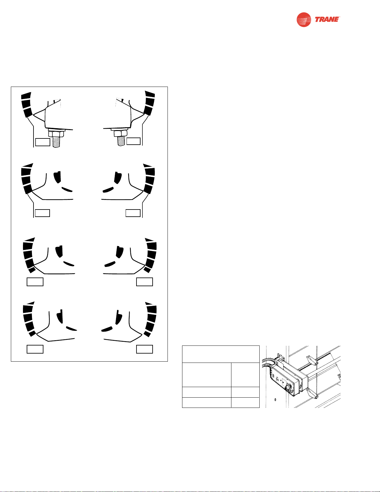
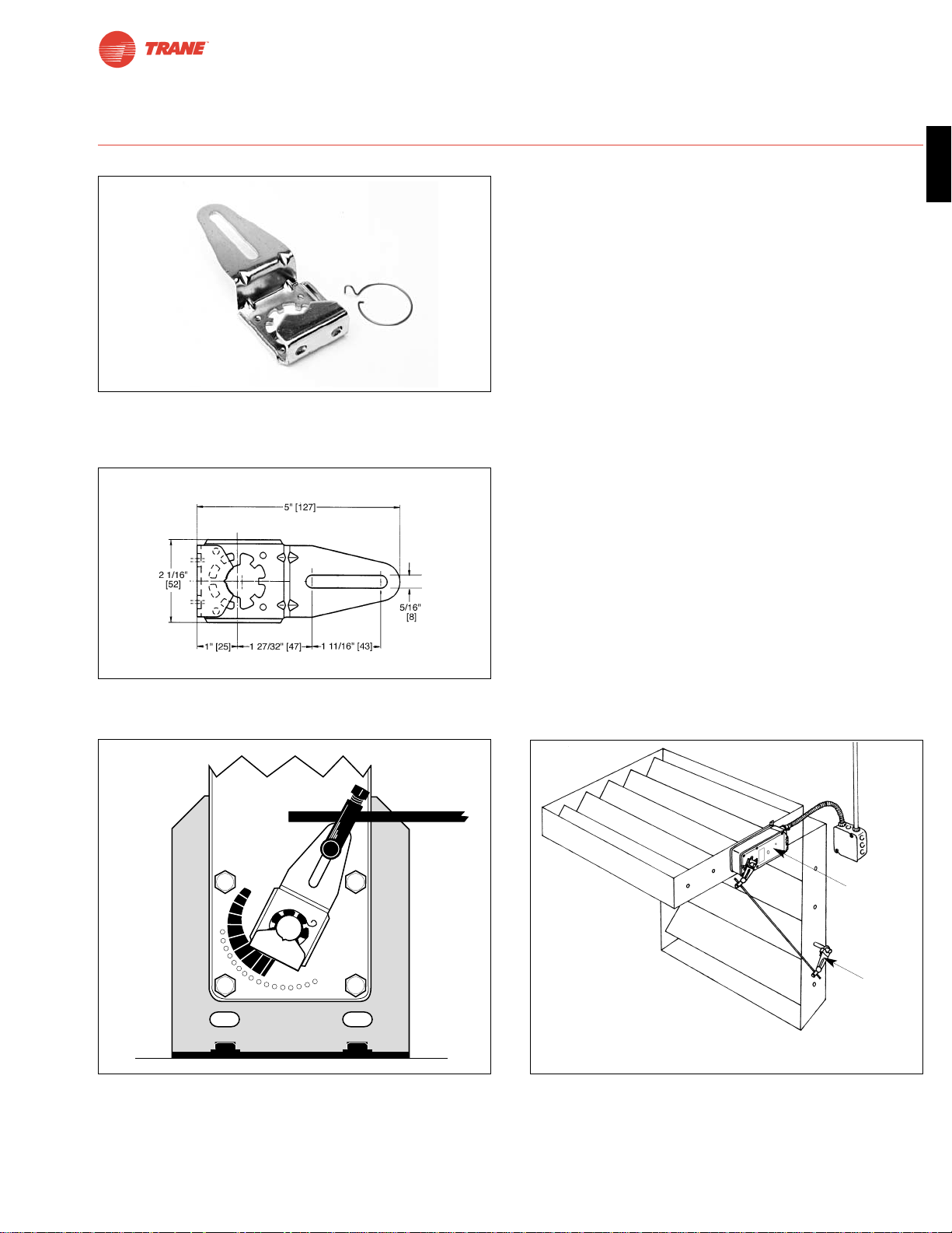
Figure A Universal Clamp and IND-AF2 Pointer (optional)
Positions Indicating Fail-Safe and Pre-load Settings
3. If the clamp is not on the correct side as determined in step
#1, re-mount the clamp as follows. If it is on the correct
side, proceed to step #5. Look at the universal clamp. If
you are mounting the actuator with the “CCW” side out,
position the clamp so that the pointer section of the tab is
pointing to 0° (see Fig. C) and the spline pattern of the
clamp mates with spline of the actuator. Slip the clamp
over the spline. (Use the same procedure if the “CW” side is
out.) If your application requires a mechanical minimum
position, read the Rotation Limiting, Mechanical Minimum
Damper Position section on page 21.
4. Lock the clamp to the actuator using the retaining clip.
5. Verify that the damper is still in its full fail-safe position.
6. Slide the actuator over the shaft.
7. Position the actuator in the desired location.
8. Tighten the two nuts on the clamp using a 10mm wrench
or socket using 6-8 ft-lb of torque.
9. Slip the stud of the anti rotation strap into the slot at the
base of the actuator. The stud should be positioned
approximately 1/16 of an inch from the closed end of the
slot. Bend the strap as needed to reach the duct. Attach
the strap to the duct with #8 self tapping screws.
Short Shaft Installation
If the shaft extends at least 3/4” from the duct, follow these
steps:
1. Determine the best orientation for the universal clamp on
the back of the actuator. The best location would be where
you have the easiest access to the V bolt nuts on the
clamp.
2. Engage the clamp to the actuator as close as possible to
the determined location.
3. Lock the clamp in place using the remaining retainer clip.
4. Verify that the damper is still in its full fail-safe position.
5. Slide the actuator over the shaft.
6. Position the actuator in the desired location.
7. Tighten the two nuts on the clamp using a 10mm wrench
or socket using 6-8 ft-lb of torque.
8. Slip the stud of the anti-rotation strap into the slot at the
base of the actuator. The stud should be positioned
approximately 1/16 of an inch from the closed end of the
slot. Bend the strap as needed to reach the duct. Attach
the strap to the duct with #8 self tapping screws.
9. If damper position indication is required, use the optional
IND-AF2 pointer. See Figure A.
Jackshaft Installation
The TAF… series actuator is designed for use with jackshafts
up to 1.05” in diameter. In most applications, the TAF actuator may be mounted in the same manner as a standard
damper shaft application. If more torque is required than one
TAF actuator can provide, a second TAF actuator may be
mounted to the jackshaft using the ZG-102 multiple actuator
mounting bracket. See wiring guide for wiring details.
Correct pointer mounting
position when actuator is
at 5° preload.
-5
-5
Correct pointer mounting
position if actuator is at
full fail-safe.
-
Correct clamp mounting
position when actuator is
shipped from factory
(with 5° preload)
CW
Correct clamp mounting
position if actuator is at
full fail-safe.
-
CCW
CWCCW
CWCCW
CWCCW
30
20
10
0
30
20
10
0
30
20
10
0
40
30
20
10
0
40
30
20
10
0
30
20
10
0
30
20
10
0
30
20
10
0
40
Mounting:
If the actuators are mounted on
the opposed ends of the shaft,
the actuator direction must be
selected carefully. Usually, the
direction of rotation is reversed.
TAF actuators which may be
used on one shaft:
Max
Quantity
Model Per Shaft
TAF24 (-S) 4
TAF24-SR 4
30
20
10
0
CCW
30
20
1
0
0
-5
40
30
20
10
0
-5
40
30
20
1
0
0
-5
Correct clamp mounting
position if actuator is at
full fail-safe.
CW
Correct pointer mounting
position if actuator is at
full fail-safe.
CCW
CW
Page 21
21
I20683 - Subject to change.
TAF
Installation Instructions
Mechanical Installation
Multiple Actuator Mounting
If more torque is required than one TAF actuator can provide,
a second TAF actuator may be mounted to the shaft using the
ZG-102 multiple mounting bracket.
Notes:The manual positioning mechanism cannot be used in
multiple actuator applications.
Special Wiring and Additional Information: See wiring guide
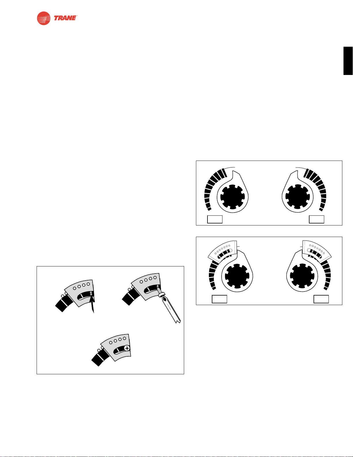
Rotation Limitation
The angle of rotation limiter, ZDB-AF2, is used in conjunction
with the tab on the universal clamp or IND-AF2 position indicator
which comes with the ZDB-AF2. In order to function properly,
the clamp or indicator must be mounted correctly. See Figure A.
The ZDB-AF2 may not work in certain mounting orientations
using the ZG-106 or ZG-107 mounting brackets. It will not work
with the ZG-108 mounting bracket. Limiting the damper rotation
must be accomplished by adjusting the crankarm linkage.
The ZDB-AF2 may be used in 2 ways to control the rotational
output of the TAF series actuator. One use is in the application where a damper has a designed rotation less than 90°.
An example would be a 45° or 60° rotating damper. The other
application would be to set a minimum damper position which
can be easily set or changed without having to remove the
actuator from the damper.
Damper Rotation Limiting
1. Determine the amount of damper rotation required.
2. Locate the Angle of Rotation Limiter (ZDB-AF2) on the
actuator so that its edge lines up with the degree graduation on the actuator face which corresponds with the
required rotation. See Figure C.
3. Find the appropriate cross-hair location through the
slot of the limiter. This is the screw mounting location.
4. Pierce through the label material to allow easy fastening of the retaining screw.
5. Position the limiter back to the desired position, making sure the locating “teeth” on the limiter are engaged
into the locating holes on the actuator.
6. Fasten the limiter to the actuator using the self tapping
screw provided.
7. Test the damper rotation either manually with the
manual crank or apply power and if required, a control
signal. Re-adjust if necessary.
Mechanical Minimum Damper Position
In order to use this procedure, the actuator must be mounted for short shaft mounting. See page 20.
1. Position the damper to its minimum position by using
the manual crank or by providing the appropriate control signal to the TAF24… modulating type actuator.
2. Place the indicator on to the actuator spline in the
approximate position shown in Figure D. Fasten it with
the retaining clip. Note that the mounting orientation is
different than the mounting used for Damper Rotation
Limiting.
3. Place the ZDB-AF2 rotation limiter on the actuator
so that it either makes contact with, or is as close as
possible to, the edge of the indicator. See Figure E.
Make sure that the locating teeth are engaged into the
locating holes on the actuator. If all of the mounting
teeth do not align with the holes, the mounting location
of the indicator to the spline may have to be moved.
The limiter would then be remounted to get the best
position match of both parts.
4. Find the cross-hair location through the slot of the
limiter. This is the screw mounting location.
5. Pierce through the label material to allow easy
fastening of the retaining screw.
6. Fasten the limiter to the actuator using the self tapping
screw provided.
7. Test the damper operation either manually with the
manual crank or apply power and if required, a control
signal. Re-adjust if necessary.
20
30
40
Screw secured at
these cross hairs
20
30
40
Secure angle-ofrotation limiter
Screw
Philips screwdriver
20
30
40
Angle of rotation
is now set at 40°.
Figure C ZDB-AF2 Securing the Angle of Rotation Limiter
100
90
8
0
70
6
0
5
0
40
3
0
20
1
0
0
10
0
90
80
7
0
60
5
0
40
30
20
10
0
CWCCW
CWCCW
60
5
0
40
3
0
20
1
0
0
60
5
0
40
30
2
0
10
0
Figure D
Figure E
Page 22
22
I20683 - Subject to change.
Installation Instructions
This method should not be used for outside air damper applications. The damper will never go to the full close-off position.
This may cause coils to freeze or other system problems. The
TAF24-SR wired to either the SGA24 or SGF24 can be used
for minimum position setting and still provide full close-off.
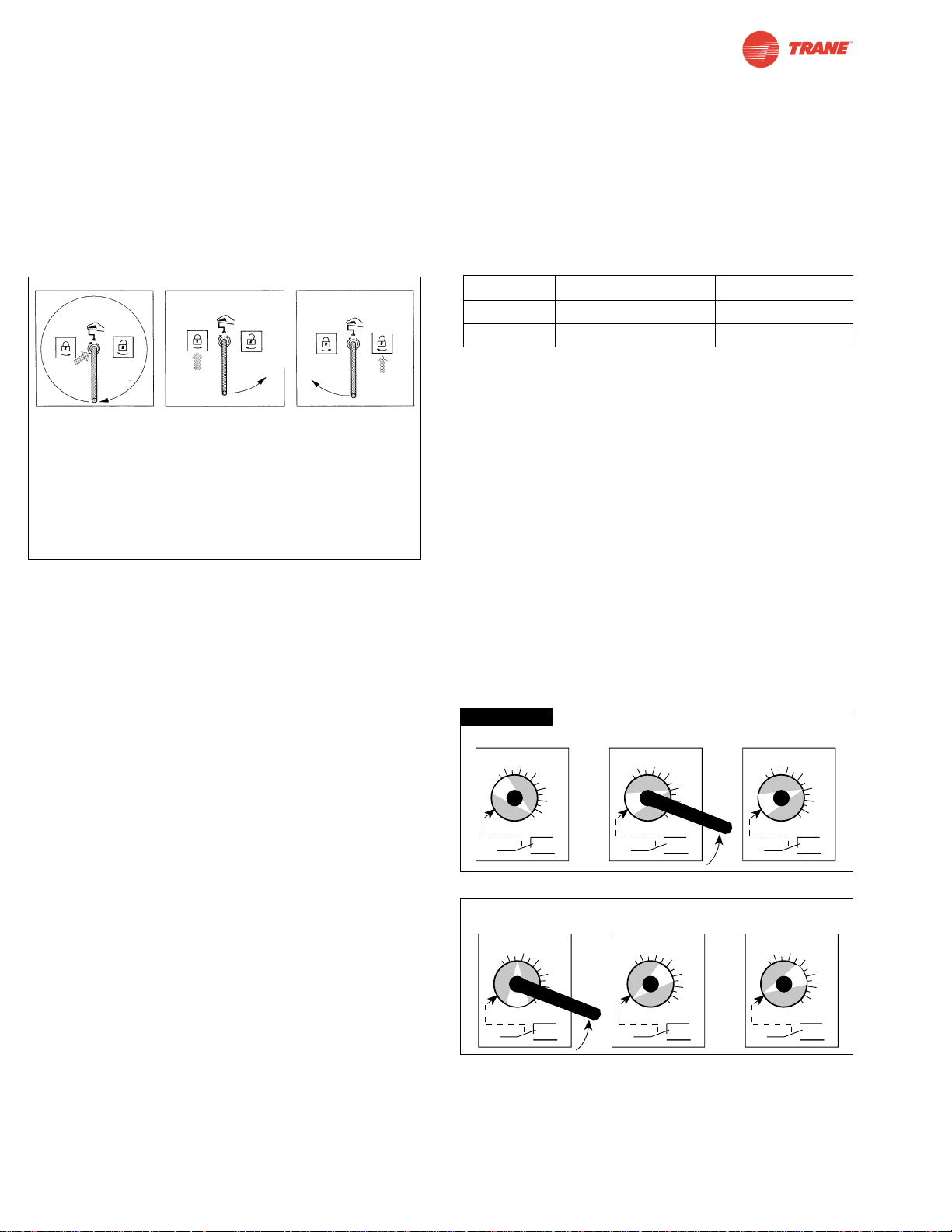
Manual Override
The TAF series actuators can be manually positioned to ease
installation or for emergency positioning.
1. The manual override will only work if no power is available
to the actuator.
2. Insert the manual crank (shipped with the actuator) into
the hexagon hole located on either side of the actuator. An
illustration, located on the label, shows the location.
3. Turn the crank in the direction shown on the label (clockwise on the “CW” side, counterclockwise on the “CCW”
side). It will take approximately 19 revolutions to rotate
the full 95° of rotation.
4. To lock the actuator in the required position, rotate the
crank quickly in the opposite direction, 1/2 of a revolution. The
“lock closed” icon on the label shows the correct direction.
5. The manual override may be disengaged in 2 ways.
- Rotate the crank about a 1/4 revolution in the same
direction as the initial winding. The “lock open” icon
shows the correct direction.
- Apply power to wire 1 and 2. The actuator will automatically disengage the override function and will go to the
“on” position in the case of the on-off versions. Or, in the
case of the proportional versions, go to the 0 signal position and then go to the position corresponding to the
control signal. The actuator will now work normally.
Testing the Installation without Power
The actuator/damper installation may be tested without power
at the actuator. Refer to the manual positioning section of the
instructions. Move the damper to its full non-fail-safe position
using the manual crank. Disengage the manual position
mechanism and have the damper go to full fail-safe position.
Correct any mechanical problems and retest.
Auxiliary Switches
The TAF series actuators may be ordered with 2 built-in SPDT
auxiliary switches used for safety interfacing or signalling, for
example, for fan start-up. The switch position near the fail-safe
position is fixed at 5°. The other is adjustable between 25 and
85° of rotation. The crank, supplied with the actuator, or a 3mm
allen wrench is used to adjust the switching position.
Switch Rating
Voltage Resistive Load Inductive Load
120 VAC 7A 5A
250 VAC 7A 2.5A
Two methods may be used to adjust the switching point of the
adjustable switch.
Method 1 - See Figure F
1 The actuator must be in its fail-safe position.
2. Insert the crank into the hexagon shaped hole located in
the center of the adjustable switch pointer.
3. Rotate the crank until the switch pointer is at the desired
switch point in degrees as shown.
Method 2 - See Figure G
1. Position the damper to the point at which you want the
switch to activate. This may be done by using the manual
override or by providing the appropriate proportional
signal to TAF24… modulating type actuator. The position
of the switch pointer is not important during this step.
2. Insert the crank into the hexagon shaped hole located in
the center of the adjustable switch pointer.
3. Rotate the switch pointer to just past the switch point
indicating arrow as shown.
30
40
50
60
70
80
25…85°
Factory setting 85°
30
40
50
60
70
80
25…85°
Rotate with
crank handle
30
40
50
60
70
80
25…85°
60° set
Crank Handle
30
40
50
60
70
80
25…85°
Actuator
after locking
30
40
50
60
70
80
25…85°
Switch operates
30
40
50
60
70
80
25…85°
Switch does
not operate
Crank Handle
Figure F
Figure G
Winding the
damper actuator
- insert crank handle
- turn handle in direction of arrow
Locking the
damper actuator
- rotate crank handle
1/2 turn in the direction shown by the
“locked” icon.
Unlocking the
damper actuator
(2 options)
- rotate crank handle
1/4 turn in the direction
shown by the
“unlocked” icon.
- remote control by supplying power to the
unit for > than 3 sec.
TAF…series
Page 23
23
I20683 - Subject to change.
TAF
Installation Instructions
Non-Direct Mounting Methods
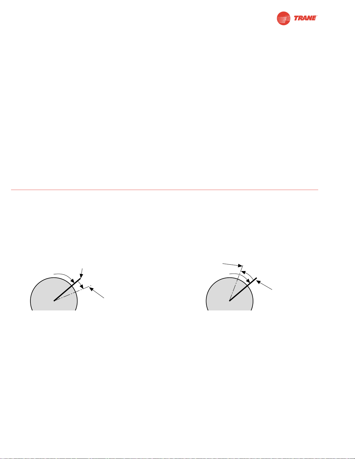
KH-AF Non-direct mounting with ZG-108 mounting bracket
Multiple dampers direct coupled to one actuator with
linkage to operate the other damper.
KH-AF Crankarm including Retaining Ring
Caution: the retaining clip supplied with the clamp is not
used to mount the KH-AF crankarm.
The KH-AF (-1) crankarm is used in non-direct coupled
mounting applications. The KH-AF (-1) may also be used to
simultaneously direct couple to a damper shaft and provide an
additional crank arm connection to a second damper. The
KH-AFV V-bolt kit must be used for this non-direct application
(see illustration below).
Two sizes are available:
KH-AF For round shafts up to 3/4” or square shafts up to 5/8”
KH-AF-1For jackshafts up to 1.05”
KH-AFV V-bolt kit for KH-AF(-1) crankarm
KH-AF (-1)
crankarm
with KH-AFV
V-bolt kit
KH-8
crankarm
Dimensions (All numbers in brackets are in millimeters.)
Page 24
24
I20683 - Subject to change.
Installation Instructions
Electrical Operation
General
The TAF series actuators utilize brushless DC motor technology. The TAF uses this motor in conjunction with an Application
Specific Integrated Circuit (ASIC). In the On-Off versions of
the TAF, the ASIC monitors and controls the actuator’s rotation and a digital rotation sensing function to prevent damage
to the actuator. The TAF24… modulating type actuators incorporate a built in microprocessor. The microprocessor provides
the intelligence to the ASIC to provide a constant rotation rate
and knows the actuator’s exact zero position.
Brushless DC Motor Operation
A brushless DC motor spins by reversing the poles of
stationary electromagnets housed inside of a rotating
permanent magnet. The electromagnetic poles are switched
by a special ASIC circuit. Unlike the conventional DC motor,
there are no brushes to wear or commutators to foul.
Overload Protection
The TAF series actuators are protected from overload at all
angles of rotation. The ASIC circuit constantly monitors the
rotation of the DC motor inside the actuator and stops the
pulses to the motor when it senses a stall condition. The DC
motor remains energized and produces full rated torque to the
load. This helps ensure that dampers are fully closed and that
edge and blade seals are always properly compressed.
Motor Position Detection
The brushless DC motors eliminate the need for potentiometers for positioning in modulating type actuators. Inside the
motor are three “Hall Effect” sensors. These sensors detect
the spinning rotor and send pulses to the microprocessor
which counts the pulses and calculates the position to within
1/3 of a revolution of the motor.
Satisfied
Control Position
Satisfied
Control Position
Minimum
Control Resolution
Minimum Reversed
Control Deadband
Prior to Normal Control
80 mV
200 mV
TAF actuator responds to a 80 mV signal
when not changing direction from stop
TAF actuator responds to a 200 mV signal
when reversing direction from stop position.
TAF24-SR actuators have built-in brushless DC motors which provide better accuracy and longer service life.
The TAF24-SR actuators are designed with a unique non-symmetrical deadband. The actuator follows an increasing or
decreasing control signal with a 80 mV resolution. If the signal changes in the opposite direction, the actuator will not respond
until the control signal changes by 200 mV. This allows these actuators to track even the slightest deviation very accurately,
yet allowing the actuator to “wait” for a much larger change in control signal due to control signal instability.
Control Accuracy and Stability
Page 25

25
I20683 - Subject to change.
TAF
General Wiring Instructions
WARNING The wiring technician must be trained and experienced with electronic circuits. Disconnect power supply
before attempting any wiring connections or changes. Make
all connections in accordance with wiring diagrams and follow
all applicable local and national codes. Provide disconnect
and overload protection as required. Use copper, twisted pair,
conductors only. If using electrical conduit, the attachment to
the actuator must be made with flexible conduit.
Always read the controller manufacturer's installation
literature carefully before making any connections. Follow
all instructions in this literature. If you have any questions,
contact the controller manufacturer.
Transformer(s)
The TAF24 . . actuators require a 24 VAC class 2 transformer
and draws a maximum of 10 VA per actuator. The actuator
enclosure cannot be opened in the field, there are no parts or
components to be replaced or repaired.
– EMC directive: 89/336/EEC
– Software class A: Mode of operation type 1
– Low voltage directive: 73/23/EEC
CAUTION: It is good practice to power electronic or digital
controllers from a separate power transformer than that used
for actuators or other end devices. The power supply design
in our actuators and other end devices use half wave rectification. Some controllers use full wave rectification. When these
two different types of power supplies are connected to the
same power transformer and the DC commons are connected
together, a short circuit is created across one of the diodes in
the full wave power supply, damaging the controller. Only use
a single power transformer to power the controller and
actuator if you know the controller power supply uses half
wave rectification.
Multiple Actuators, One Transformer
Multiple actuators may be powered from one transformer
provided the following rules are followed:
1. The TOTAL current draw of the actuators (VA rating) is
less than or equal to the rating of the transformer.
2. Polarity on the secondary of the transformer is strictly
followed. This means that all No. 1 wires from all
actuators are connected to the common leg on the
transformer and all No. 2 wires from all actuators are
connected to the hotleg. Mixing wire No. 1 & 2 on one leg
of the transformer will result in erratic operation or failure
of the actuator and/or controls.
Multiple Actuators, Multiple Transformers
Multiple actuators positioned by the same control signal may
be powered from multiple transformers provided the following
rules are followed:
1. The transformers are properly sized.
2. All No. 1 wires from all actuators are tied together and tied
to the negative leg of the control signal. See wiring diagram.
Wire Length for TAF… Actuators
Keep power wire runs below the lengths listed in the Figure H.
If more than one actuator is powered from the same wire run,
divide the allowable wire length by the number of actuators to
determine the maximum run to any single actuator.
Example: 3 actuators, 16 Ga wire
350 ft ÷ 3 Actuators = 117 ft. maximum wire run
Maximum Wire Length:
Wire Size Max. Feet. Wire Size Max. Feet
12 Ga 900 Ft. 18 Ga 225 Ft.
14 Ga 550 Ft. 20 Ga 125 Ft.
16 Ga 350 Ft. 22 Ga 60 Ft.
Figure H
Wire Type and Wire Installation Tips
For most installations, 18 or 16 Ga. cable works well with the
TAF24. . actuators. Use code-approved wire nuts, terminal
strips or solderless connectors where wires are joined. It is
good practice to run control wires unspliced from the actuator
to the controller. If splices are unavoidable, make sure the
splice can be reached for possible maintenance. Tape and/or
wire-tie the splice to reduce the possibility of the splice being
inadvertently pulled apart.
The TAF24… proportional actuators have a digital circuit that
is designed to ignore most unwanted input signals (pickup).
In some situations the pickup may be severe enough to cause
erratic running of the actuator. For example, a large inductive
load (high voltage AC wires, motors, etc.) running near the
power or control wiring may cause excessive pickup. To
solve this problem, make one or more of the following
changes:
1. Run the wire in metallic conduit.
2. Re-route the wiring away from the source of pickup.
3. Use shielded wire (Belden 8760 or equal). Ground the
shield to an earth ground. Do not connect it to the
actuator common.
Initialization of the TAF24-SR
When power is initially applied, the actuator will first release its
manual preload position (This assumes a manual position has
been set). The actuator will then rotate to the full fail-safe
position. At this point the microprocessor recognizes that the
actuator is at full fail-safe and uses this position as the base
for all of its position calculations. The microprocessor will
retain the initialized zero during short power failures of up to
20 seconds. For power failures greater than 20 seconds, the
actuator would naturally return to its full fail-safe position prior
to the microprocessor losing its memory. The actuator will also
re-initialize if the manual position mechanism is used.
Installation Instructions
General Wiring
Page 26

26
I20683 - Subject to change.
Startup and Checkout
Instructions for TAF24-SR + P-100…
Procedure
Control signal is applied to actuator.
Check power wiring. Correct any
problems. See Note 1.
Turn reversing switch to the correct
position. Make sure the switch is
turned all the way left or right.
Make sure the control signal positive
(+) is connected to Wire No 3 and
control signal negative (-) is connected to wire No. 1. Most control problems are caused by reversing these
two wires. Verify that the reversing
switch is all the way CCW or CW.
Check input signal with a digital volt
meter (DVM). Make sure the input
is within the range of the actuator.
For TAF24-SR this is 2 to 10 VDC or
4 to 20 mA.
Note: The input signal must be above
the 2 VDC or 4 mA to have the
actuator move.
Loosen the nuts on the V-bolt and
move the damper by hand from fully
closed to fully open.
Check damper torque requirement.
Actuator works properly. Test
controller by following controller
manufacturer's instructions.
Expected Response
Actuator will move to its “Control
Signal” position.
Power supply rating should be
≥
the total power requirement of
the actuator(s). Minimum voltage of 19.2 VAC or 21.6 VDC.
Actuator will move to its “Control
Signal” position.
Drives to “Control Signal”
position.
Input voltage or current should
be ±1% of what controller's
adjustment or programming
indicate.
Damper will go from fully closed
to fully open.
Torque requirement is ≤
actuator’s minimum torque.
Gives Expected
Response
Go To Step…
Actuator operates
properly.
Step 7
Power wiring correct-
ed, actuator begins
to drive.
Step 1
Actuator operates
properly.
Step 7
Actuator operates
properly.
Step 7
Controller output
(actuator input) is
correct. Input
Polarity Correct.
Step 6
Damper moves
properly.
Step 7
Defective Actuator.
Replace Actuator.
Does Not Give
Expected Response
Go To Step…
No response at all.
Step 2
Operation is
reversed.
Step 3
Does not drive
toward "Control
Signal Position".
Step 4
Power wiring
corrected, actuator
still does not drive.
Step 4
Does not drive
toward “Control
Signal Position”.
Step 4
Step 5
Reprogram, adjust
repair or replace
controller as needed.
Step 1
Find cause of damper
jam and repair. Move
damper back to the
fully closed position
and tighten the nuts.
Step 1
Recalculate actuator
requirement and
correct installation.
Step
1.
2.
3.
4.
5.
6.
7.
8.
TAF24-SR + P-100… Electrical Check-out Procedure
Note 1 Check that the transformer(s) are sized properly.
• If a common transformer is used, make sure that polarity is observed on the secondary. This means connect all No. 1
wires to one leg of the transformer and all No. 2 wires to the other leg of the transformer.
• If multiple transformers are used with one control signal, make sure all No. 1 wires are tied together and tied to control
signal negative (-).
• Controllers and actuators must have separate 24 VAC/VDC power sources.
Page 27

27
I20683 - Subject to change.
TAF
Notes/Work Pad
Page 28
TNF24-S (p. 30)
28
I20683 - Subject to change.
TNF Series Spring Return Direct Coupled Actuator
Minimum 60 in-lb Torque
● For damper areas up to 15 sq-ft*
Torque: 60 in-lb ●●●
Power supply : 24 VAC ●●●
Control signal: on-off ●●
proportional 2 to 10 VDC ●
Feedback signal: 2 to 10 VDC ●
Running time motor: <75 sec ●●
150 sec constant ●
spring: <60 sec ●●●
Brushless DC Motor ●
External direction of rotation switch ●
Appliance rated cable, 18 GA ●●●
Built-in auxiliary switch 1SPDT ●
Installation instructions......(p. 34–39) General wiring ..............(p. 40)
Startup and checkout ........(p. 41)
*Based on 4 in-lb/ft2damper torque loading. Parallel blade. No edge seals.
TNF Series – AT A Glance
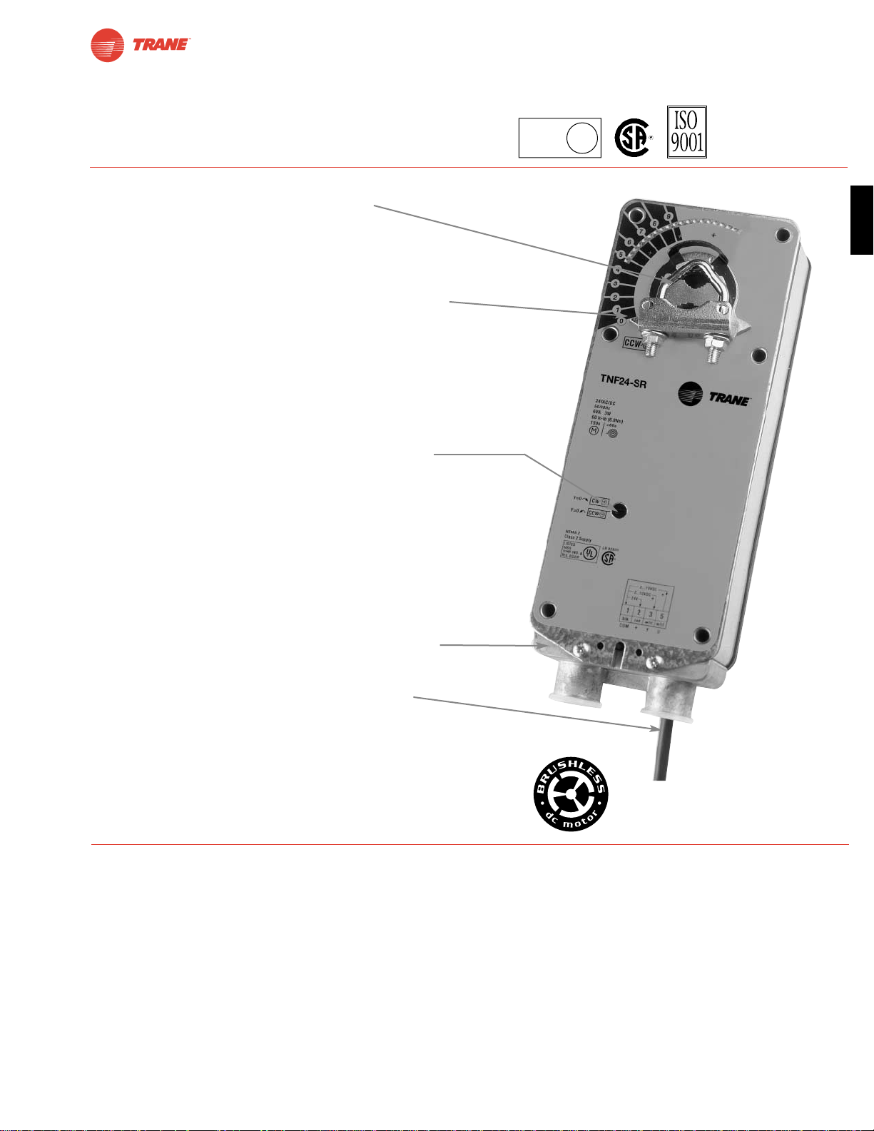
K4-1 US
Clamp
ZG106 or
ZG 107
bracket
Mount directly to 1.05” jackshafts with
accessory clamp.
Linkage is available when direct coupling is
not possible.
TNF24 (p. 30)
TNF24-SR (p. 32)
Applications
Page 29
29
I20683 - Subject to change.
TNF
A CLOSER LOOK…
TNF Series Spring Return Direct Coupled Actuator
● Cut labor costs with simple direct coupling.
● True mechanical spring return – the most reliable fail-safe.
● Mount for clockwise or counterclockwise fail-safe.
● Check damper position easily with clear position indicator.
● Don’t worry about actuator burn-out, it is overload-proof
throughout rotation.
● Easy mechanical stop to adjust angle of rotation.
(add ZDB-AF2 accessory).
● Need to change control direction?
Do it easily with a simple switch. (modulating actuators).
● Golden Point breather membrane optimizes
performance in harsh airstream environments.
● Built-in auxiliary switch is easy to use, offers feedback
or signal for additional device.
● Microprocessor-controlled brushless DC motor increases
actuator life span and reliability, provides constant running
time (modulating actuators).
● Rugged metal housing withstands rough handling in the
mechanical room.
● 3 ft. appliance rated cable and conduit connector
eases installation.
The T rane Difference
● Low Installation and Life-Cycle Cost.
Easy installation. Accuracy and repeatability.
Low power consumption. No maintenance.
●
Long Service Life.
Components tested before assembly. Every product tested before shipment.
30+ years direct coupled actuator design.
©
LISTED
94D5
TEMP. IND &
REG. EQUIP.
U
L
Page 30
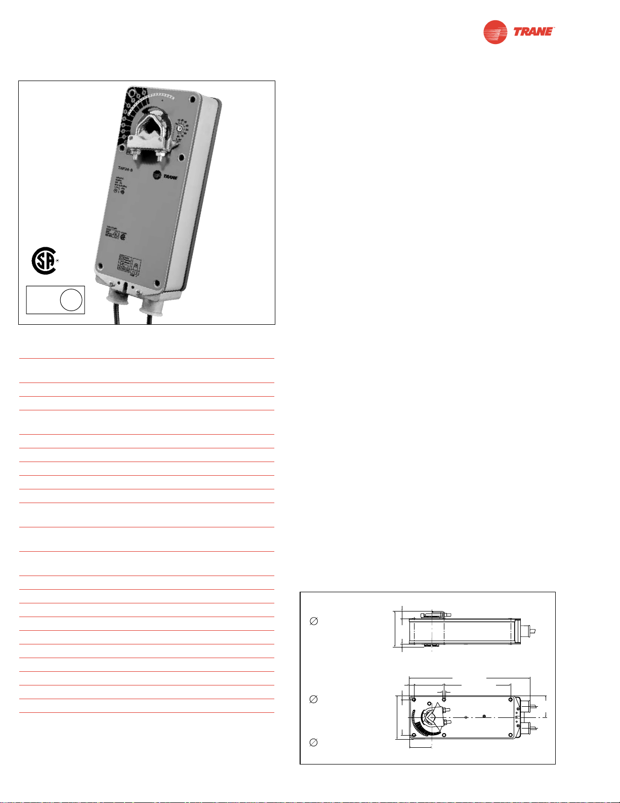
I20683 - Subject to change.
Torque min. 60 in-lb, for control of air dampers
Application
For on-off, fail-safe control of dampers in HVAC systems.
Actuator sizing should be done in accordance with the damper
manufacturer’s specifications. Control is on-off from an
auxiliary contact, or a manual switch.
The actuator is mounted directly to a damper shaft up to 1.05”
in diameter by means of its universal clamp. A crank arm and
several mounting brackets are available for applications where
the actuator cannot be direct coupled to the damper shaft.
Operation
The TNF series actuators provide true spring return operation
for reliable fail-safe application and positive close off on air tight
dampers. The spring return system provides constant torque to
the damper with, and without, power applied to the actuator.
The TNF series provides 95° of rotation and is provided with a
graduated position indicator showing 0° to 95°.
The actuator may be stalled anywhere in its normal rotation
without the need of mechanical end switches.
The TNF24-S version is provided with one built in auxiliary
switch. This SPDT switch is provided for safety interfacing or
signaling, for example, for fan start-up. The switching function
is adjustable between 5° and 85°.
For all accessories, see pages 110 and 132.
TNF24 (-S)
On-off, Spring Return Fail-Safe, 24 V
Technical Data TNF24 (-S)
Power supply 24 VAC ± 20% 50/60 Hz
24 VDC ± 10%
Power consumption running: 5 W; holding: 2.6 W
Transformer sizing 8 VA (class 2 power source)
Electrical connection 3 ft, 18 GA appliance cable
1/2” conduit connector
Overload protection Electronic throughout 0° to 95° rotation
Electrical protection Auxiliary switches are double insulated
Angle of rotation 95°, adjustable 30 to 95° w/ accessories
Torque 60 in-lb [7 Nm] constant torque
Direction of rotation reversible with CW/CCW mounting.
Position indication visual indicator, 0° to 95° (0° is spring
return position)
Auxiliary switches 1 x SPDT 7A (2.5A) @ 250 VAC,
UL listed
adjustable 5°to 85°
Running time motor: < 75 sec
spring: < 60 sec
Humidity 5 to 95% RH non-condensing
Ambient temperature -22°F to +122°F [-30°C to +50°C]
Storage temperature -40°F to +176°F [-40°C to +80°C]
Housing NEMA type 2 / IP54
Housing material zinc coated steel
Agency listings UL 873 listed, CSA C22.2 No.24 certified
Noise level max. 45 dB (A)
Servicing maintenance free
Quality standard ISO 9001
Weight 6.6 lbs (3.0 kg.)
(TNF24-S)
(nominal)
Dimensions [All numbers in brackets are in millimeters.]
LISTED
94D5
TEMP. IND &
REG. EQUIP.
U
L
D011
30
K4-2 US (supplied)
1/2" Centered
(Default)
3/4" Centered
(Field Selectable)
1.05" Centered
(Field Selectable)
K4-1 US (optional)
3/4" to 1.05"
Adjustable
K4 US (optional)
3/8" to 3/4"
Adjustable
0.65" [16.5]
3.25" [82.7]
0.19" [5]
0.39" [10]
0.35" [9]
3.86" [98]
[57]
2.24"
3.15" [80]
1.97"
[50]
2.64"
[67]
10.59" [269]
5.85" [148.5]
0.26" [6.5]
1.93"
[49]
Page 31
31
I20683 - Subject to change.
TNF
TNF24 (-S)
On-off, Spring Return Fail-Safe, 24 V
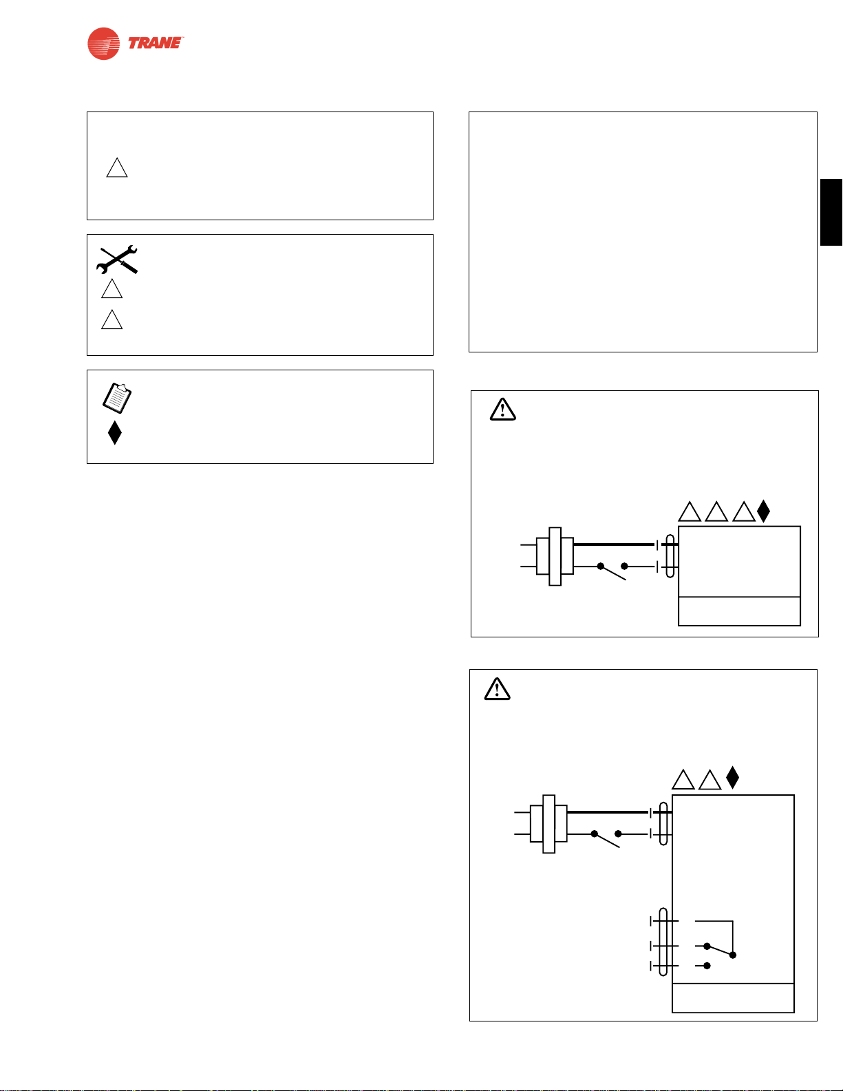
Wiring Diagrams
TNF24 Typical Specification
On-off spring return damper actuators shall be direct
coupled type which require no crankarm and linkage and
be capable of direct mounting to a jackshaft up to a 1.05”
diameter. The actuators must be designed so that they may
be used for either clockwise or counterclockwise fail-safe
operation. Actuators shall be protected from overload at all
angles of rotation. If required, one SPDT auxiliary switch
shall be provided having the capability of being adjustable.
Actuators with auxiliary switches must be constructed to
meet the requirements for Double Insulation so an electrical
ground is not required to meet agency listings. Actuators are
UL listed and CSA certified and be manufactured under ISO
9001 International Quality Control Standards. Actuators
shall be as manufactured by Belimo.
1 Common
2 + Hot
2
24 VAC Transformer
TNF24
Line
Volts
35
WARNING
Live Electrical Components!
During installation, testing, servicing and troubleshooting of this product, it maybe
necessary to work with live electrical components. Have a qualified licensed electrician
or other individual who has been properly trained in handling live electrical components
perform these tasks. Failure to follow all electrical safety precautions when exposed
to live electrical components could result in death or serious injury.
1 Common
2 + Hot
2
24 VAC Transformer
TNF24-S
Line
Volts
3
S1
S2
S3
NC
NO
5° to 85°
WARNING
Live Electrical Components!
During installation, testing, servicing and troubleshooting of this product, it maybe
necessary to work with live electrical components. Have a qualified licensed electrician
or other individual who has been properly trained in handling live electrical components
perform these tasks. Failure to follow all electrical safety precautions when exposed
to live electrical components could result in death or serious injury.
On-off wiring for TNF24
On-off wiring for TNF24-S
W454
W455
3
5
Actuator may also be powered by 24 VDC.
Actuators with plenum rated cable do not have
numbers on wires; use color codes instead.
Actuators with appliance cables use numbers.
Meets cULus or UL and CSA requirements without
the need of an electrical ground connection.
CAUTION
2
Equipment damage!
Actuators may be connected in parallel. Power consumption and input impedance must be observed.
INSTALLATION NOTES
APPLICATION NOTES
Page 32
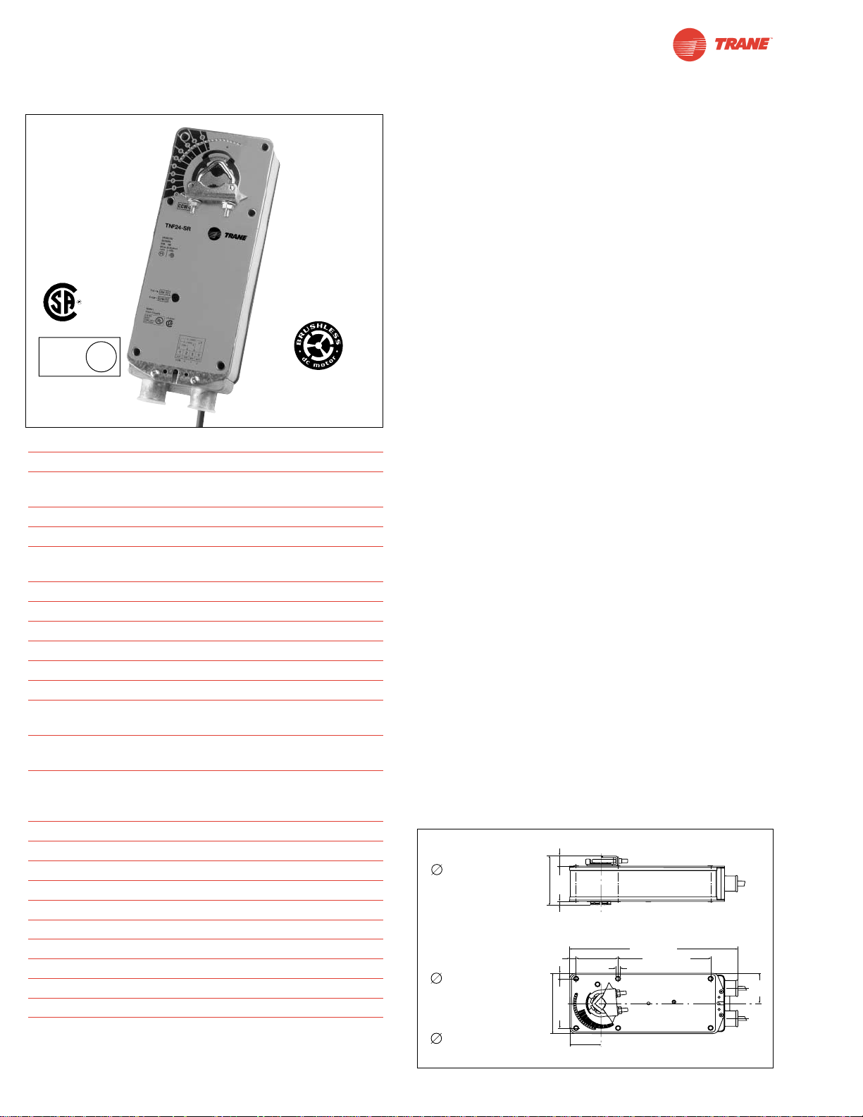
I20683 - Subject to change.
TNF24-SR
Proportional Damper Actuator, Spring Return Fail-Safe, 24 V for 2 to 10 VDC, or 4 to 20 mA Control Signal.
Output Signal of 2 to 10 VDC for Position Indication
Torque min. 60 in-lb, for control of air dampers
Application
For proportional modulation of dampers in HVAC systems.
Actuator sizing should be done in accordance with the damper
manufacturer’s specifications.
The actuator is mounted directly to a damper shaft up to 1.05”
in diameter by means of its universal clamp. A crank arm and
several mounting brackets are available for applications where
the actuator cannot be direct coupled to the damper shaft.
The actuator operates in response to a 2 to 10 VDC, or with the
addition of a 500Ω resistor, a 4 to 20 mA control input from an
electronic controller or positioner. A 2 to 10 VDC feedback signal
is provided for position indication or master-slave applications.
Operation
The TNF series actuators provide true spring return operation
for reliable fail-safe application and positive close-off on air tight
dampers. The spring return system provides constant torque to
the damper with, and without, power applied to the actuator.
The TNF series provides 95° of rotation and is provided with a
graduated position indicator showing 0° to 95°.
The TNF24-SR uses a brushless DC motor which is
controlled by an Application Specific Integrated Circuit (ASIC)
and a microprocessor. The microprocessor provides the
intelligence to the ASIC to provide a constant rotation rate and
to know the actuator’s exact fail-safe position. The ASIC
monitors and controls the brushless DC motor’s rotation and
provides a digital rotation sensing function to prevent damage
to the actuator in a stall condition. The actuator may be stalled
anywhere in its normal rotation without the need of
mechanical end switches.
For all accessories, see pages 110 and 132.
Technical Data TNF24-SR
Power supply 24 VAC ± 20% 50/60 Hz
24 VDC ± 10%
Power consumption running: 3 W; holding: 1 W
Transformer sizing 6 VA (class 2 power source)
Electrical connection 3 ft, 18 GA appliance cable
1/2” conduit connector
Overload protection Electronic throughout 0° to 95° rotation
Operating range Y 2 to 10 VDC, 4 to 20mA
Input impedance 100 kΩ (0.1 mA), 500Ω
Feedback output U 2 to 10 VDC (max. 0.5 mA) for 95°
Angle of rotation 95°, adjustable 30° to 95° w/accessory
Torque 60 in-lb [7 Nm] constant torque
Direction of rotation spring: reversible with cw/ccw mounting
motor: reversible with built-in switch
Position indication visual indicator, 0° to 95°
(0° is spring return position)
Running time motor: 150 sec constant,
independent of load
spring: < 60 sec
Humidity 5 to 95% RH non-condensing
Ambient temperature -22°F to +122°F [-30°C to +50°C]
Storage temperature -40°F to +176°F [-40°C to +80°C]
Housing NEMA type 2 / IP54
Housing material zinc coated metal
Agency listings UL 873 listed, CSA C22.2 No.24 certified
Noise level max. 45 dB (A)
Servicing maintenance free
Quality standard ISO 9001
Weight 6.0 lbs (2.7 kg.)
LISTED
94D5
TEMP. IND &
REG. EQUIP.
U
L
(nominal)
Dimensions [All numbers in brackets are in millimeters.]
D011
32
©
K4-2 US (supplied)
1/2" Centered
(Default)
3/4" Centered
(Field Selectable)
1.05" Centered
(Field Selectable)
K4-1 US (optional)
3/4" to 1.05"
Adjustable
K4 US (optional)
3/8" to 3/4"
Adjustable
0.65" [16.5]
3.25" [82.7]
0.19" [5]
0.39" [10]
0.35" [9]
3.86" [98]
[57]
2.24"
3.15" [80]
1.97"
[50]
2.64"
[67]
10.59" [269]
5.85" [148.5]
0.26" [6.5]
1.93"
[49]
Page 33
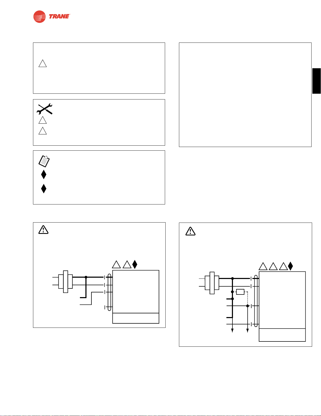
33
I20683 - Subject to change.
TNF
TNF24-SR
Proportional Damper Actuator, Spring Return Fail-Safe, 24 V for 2 to 10 VDC, or 4 to 20 mA Control Signal.
Output Signal of 2 to 10 VDC for Position Indication
TNF24-SR Typical Specification
Spring return control damper actuators shall be direct
coupled type which require no crankarm and linkage and
be capable of direct mounting to a jackshaft up to a 1.05”
diameter. The actuator must provide proportional damper
control in response to a 2 to 10 VDC or, with the addition
of a 500Ω resistor, a 4 to 20 mA control input from an
electronic controller or positioner. The actuators must be
designed so that they may be used for either clockwise or
counterclockwise fail-safe operation. Actuators shall use a
brushless DC motor controlled by a microprocessor and be
protected from overload at all angles of rotation. Run time
shall be constant, and independent of torque. A 2 to 10 VDC
feedback signal shall be provided for position feedback or
master-slave applications. Actuators are UL listed and CSA
certified and be manufactured under ISO 9001 International
Quality Control Standards. Actuators shall be
as manufactured by Belimo.
Wiring Diagrams
Control Signal
(+)
2 to 10 VDC
(–)
1 Common
2 + Hot
3 Y1 Input,
2 to 10V
5 U Output 2 to 10V
2
3
24 VAC Transformer
TNF24-SR
Line
Volts
WARNING
Live Electrical Components!
During installation, testing, servicing and troubleshooting of this product, it maybe
necessary to work with live electrical components. Have a qualified licensed electrician
or other individual who has been properly trained in handling live electrical components
perform these tasks. Failure to follow all electrical safety precautions when exposed
to live electrical components could result in death or serious injury.
1 Common
2 + Hot
3 Y
1
Input, 2 to 10V
5 U Output 2 to 10V
24 VAC Transformer
5
3
2
TNF24-SR
Control Signal
(+)
4 to 20 mA
(–)
Feedback Signal
(+)
2 to 10 VDC
(–)
Ω
500Ω
Line
Volts
To other
actuators
WARNING
Live Electrical Components!
During installation, testing, servicing and troubleshooting of this product, it maybe
necessary to work with live electrical components. Have a qualified licensed electrician
or other individual who has been properly trained in handling live electrical components
perform these tasks. Failure to follow all electrical safety precautions when exposed
to live electrical components could result in death or serious injury.
4 to 20 mA control of TNF24-SR with 2 to 10 VDC
feedback output
0 to 10 VDC control of TNF24-SR
W456
W457
2
Equipment damage!
Up to 4 actuators may be connected in parallel.
With 4 actuators wired to one 500Ω resistor.
Power consumption must be observed and input
impedance must be observed.
3
5
Actuator may also be powered by 24 VDC.
Only connect common to neg. (—) leg of
control circuits
Meets cULus or UL and CSA requirements without
the need of an electrical ground connection.
The ZG-R01 500Ω resistor converts the 4 to 20 mA
control signal to 2 to 10 VDC.
CAUTION
INSTALLATION NOTES
APPLICATION NOTES
Page 34
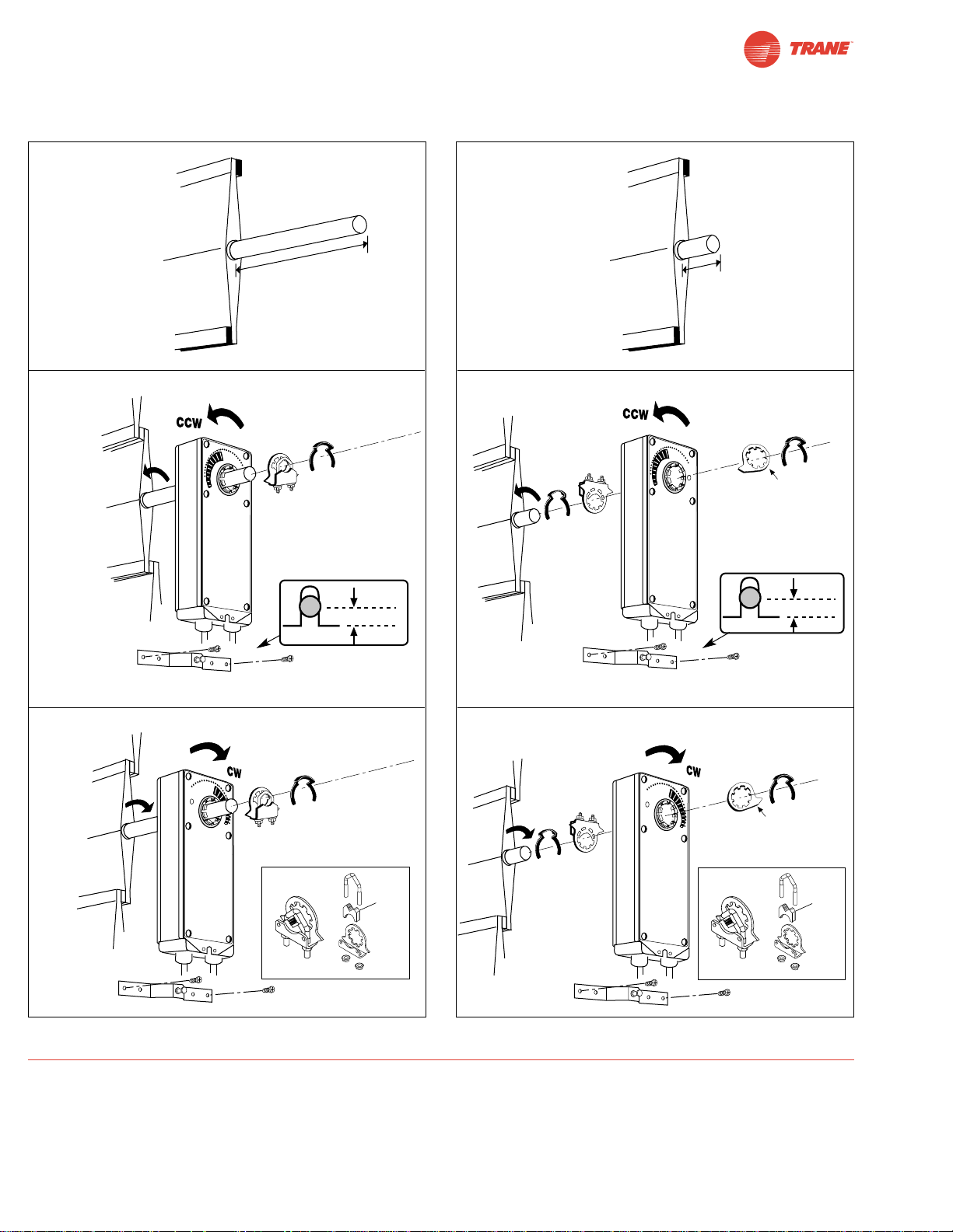
34
I20683 - Subject to change.
Installation Instructions
Quick-Mount Visual Instructions for Mechanical Installation
IND-AF2 Position Indicator
(optional)
Quick-Mount Visual Instructions
1. Rotate the damper to its failsafe position. If the shaft rotates
counterclockwise, mount the “CCW” side of the actuator out.
If it rotates clockwise, mount the actuator with the “CW” side
out.
2. If the universal clamp is not on the correct side of the
actuator, move it to the correct side for ease of installation.
3. Slide the actuator onto the shaft and tighten the nuts on the
V-bolt with a 10 mm wrench to 6-8 ft-lb of torque.
4. Slide the anti-rotation strap under the actuator so that it
engages the slot at the base of the actuator. Secure the
strap to the duct work with #8 self-tapping screws.
NOTE: Read the “Standard Mounting” instructions, on the next
page, for more detailed information.
min. 3 1/2"
[90]
min. 3/4"
[20]
Dimensions [All numbers in brackets are in millimeters.]
Remove
for 3/4”
to 1.05”
shafts
Remove
for 3/4”
to 1.05”
shafts
1/4” [6.35 mm]
1/4” [6.35 mm]
IND-AF2 Position Indicator
(optional)
Page 35

35
I20683 - Subject to change.
TNF
Installation Instructions
Mechanical Installation
Standard Mounting
Mechanical Operation
The actuator is mounted directly to a damper shaft up to 1.05” in diameter by means of its universal clamp. A crank arm and
several mounting brackets are available for applications where the actuator cannot be direct coupled to the damper shaft.
The TNF series actuators provide true spring return operation for reliable fail-safe application and positive close-off on air tight
dampers. The spring return system provides consistent torque to the damper with, and without, power applied to the actuator.
The TNF series provides 95° of rotation and is provided with a graduated position indicator showing 0° to 95°.
The TNF…-S versions are provided with one built-in auxiliary switch. This SPDT switch is provided for safety interfacing or
signaling, for example, for fan start-up. The switching function is adjustable between 5° and 85°.
1. See Fig. B. Manually move the damper to the fail-safe
position (a) (usually closed). If the shaft rotated counterclockwise ( ), this is a CCW installation. If the shaft
rotated clockwise ( ), this is a CW installation. In a
CCW installation, the actuator side marked “CCW” faces
out, while in a CW installation, the side marked “CW”
faces out. All other steps are identical.
2. The actuator is usually shipped with the universal clamp
mounted to the “CCW” side of the actuator. To test for
adequate shaft length, slide the actuator over the shaft
with the side marked “CCW” (or the “CW” side if this is the
side with the clamp). If the shaft extends at least 1/8”
through the clamp, mount the actuator as follows. If not,
go to the Short Shaft Installation section.
Determining Torque Loading and Actuator Sizing
Damper torque loadings, used in selecting the correct size actuator, should be provided by the damper manufacturer. If this
information is not available, the following general selection guidelines can be used.
Damper Type Torque Loading
Opposed blade, without edge seals, for non-tight close-off applications 3 in-lb/sq. ft.
Parallel blade, without edge seals, for non-tight close-off applications 4 in-lb/sq. ft.
Opposed blade, with edge seals, for tight close-off applications 5 in-lb/sq. ft.
Parallel blade, with edge seals, for tight close-off applications 7 in-lb/sq. ft.
The above torque loadings will work for most applications under 2 in. w.g. static pressure or 1000 FPM face velocity. For
applications between this criteria and 3 in. w.g. or 2500 FPM, the torque loading should be increased by a multiplier of 1.5.
If the application calls for higher criteria up to 4 in. w.g. or 3000 FPM, use a multiplier of 2.0.
General Information
Trane actuators should be mounted indoors in a dry, relatively clean environment free from corrosive fumes. If the actuator is to be
mounted outdoors, a protective enclosure must be used to shield the actuator.
For new construction work, order dampers with extended shafts. Instruct the installing contractor to allow space for mounting and
service of the actuator on the shaft. The damper shaft must extend at least 3 1/2" from the duct. If the shaft extends less than 3 1/2" or
if an obstruction blocks access, the shaft can be extended with the AV 10-18 shaft extension or the actuator may be mounted in its short
shaft configuration.
Page 36
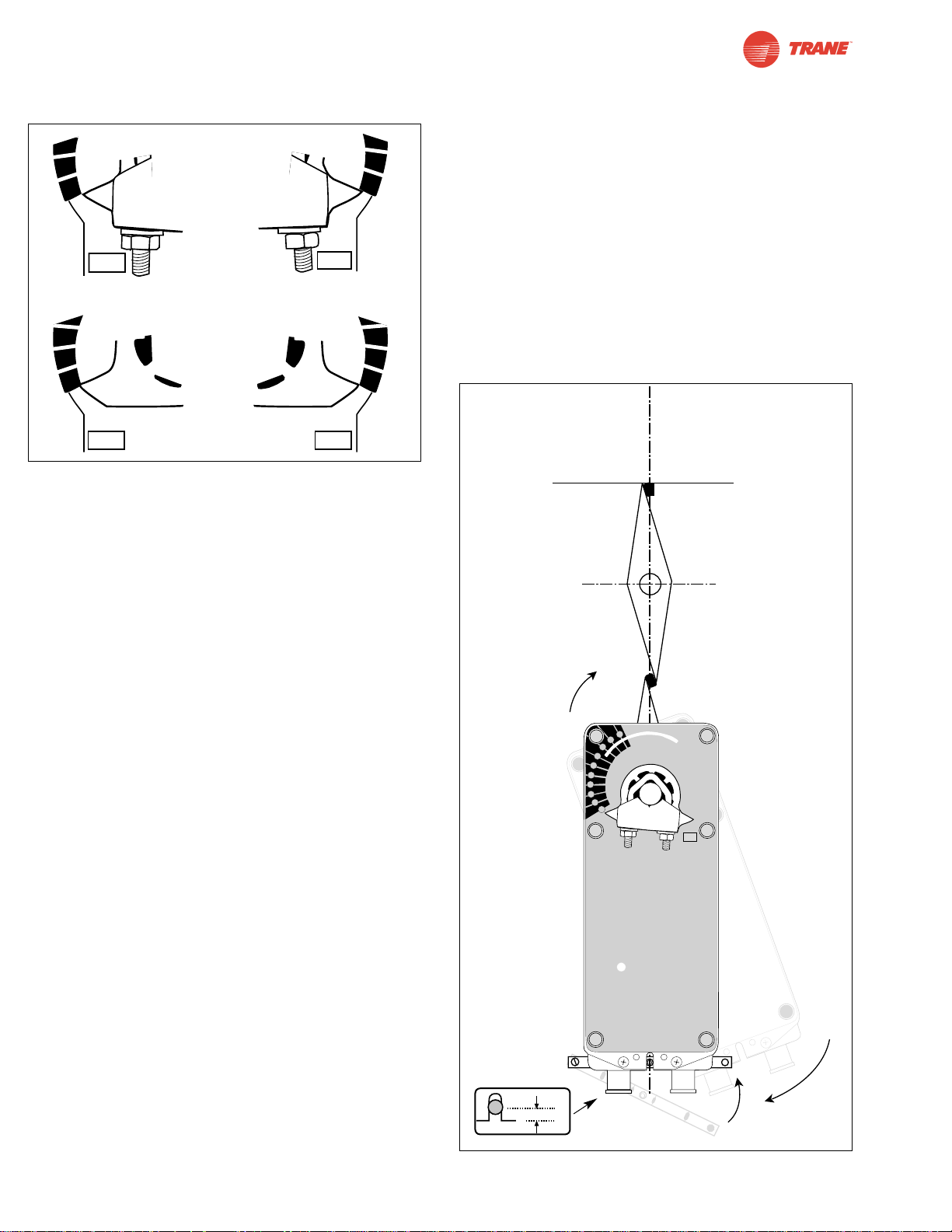
36
I20683 - Subject to change.
Installation Instructions
Mechanical Installation
Figure A Universal Clamp and IND-AF2 Position
Indicator (optional)
3. If the clamp is not on the correct side as determined in step
#1, re-mount the clamp as follows. If it is on the correct
side, proceed to step #5. Look at the universal clamp. If
you are mounting the actuator with the “CCW” side out,
position the clamp so that the pointer section of the tab is
pointing to 0° (see Fig. C) and the spline pattern of the
clamp mates with spline of the actuator. Slip the clamp
over the spline. (Use the same procedure if the “CW” side is
out.) If your application requires a mechanical minimum
position, read the Rotation Limitation section.
4. Lock the clamp to the actuator using the retaining clip.
5. Verify that the damper is still in its full fail-safe position (a).
6. Mount the spring return actuator to the shaft. Tighten the
universal clamp, finger tight only.
7. Mount the anti-rotation strap at the base of the actuator.
Slip the stop of the anti-rotation strap in the slot of the base
of the actuator. The stud should be centered approximately
1/4” from the end of the slot. Do not tighten the screws.
8. Remove the screw from one end of the mounting bracket
and pivot it away from the actuator.
9. Loosen the universal clamp and, making sure not to move
the damper shaft, rotate the actuator approximately 5° in
the direction which would open the damper.
10. Tighten the universal clamp to the shaft.
11. Rotate the actuator to apply pressure to the damper seals
(b) and re-engage the anti-rotation strap (c).
12. Tighten all fasteners.
Short Shaft Installation
If the shaft extends at least 3/4” from the duct, follow these
steps:
1. Move damper blades to the fail-safe position (a).
2. Determine the best orientation for the universal clamp on the
back of the actuator. The best location would be where you
have the easiest access to the V bolt nuts on the clamp.
3. Engage the clamp to the actuator as close as possible to
the determined location.
4. Lock the clamp to the actuator using the retainer clip.
5. Mount the spring return actuator to the shaft. Tighten the
universal clamp, finger tight only.
6. Mount the anti-rotation strap at the base of the actuator.
Do not tighten the screws.
7. Remove the screw from one end of the mounting bracket
and pivot it away from the actuator.
8. Loosen the universal clamp and, making sure not to move
the damper shaft, rotate the actuator approximately 5° in
the direction which would open the damper.
9. Verify that the damper is still in its full fail-safe position.
10. Tighten the universal clamp to the shaft.
11. Rotate the actuator to apply pressure to the damper seals
(b) and re-engage the anti-rotation strap (c).
12. Tighten all fasteners.
30
20
10
0
CCW
30
20
1
0
0
-5
Correct clamp mounting
position if actuator is at
full fail-safe.
40
30
20
10
0
-5
40
30
20
1
0
0
-5
Correct pointer mounting
position if actuator is at
full fail-safe.
CW
CCW
CW
Figure B
R
5°
M
1
2
S1S
2
(C
O
M
)
(+
)
M
a
de in
S
w
i
tz
e
rl
an
d
30
40
50
6
0
70
8
0
25
…
85
°
90
80
7
0
60
0
-5
L
C
9
8
-
5
b
c
a
CW
1
2
3
4
5
6
7
8
9
0
1/4” [6.35 mm]
Page 37
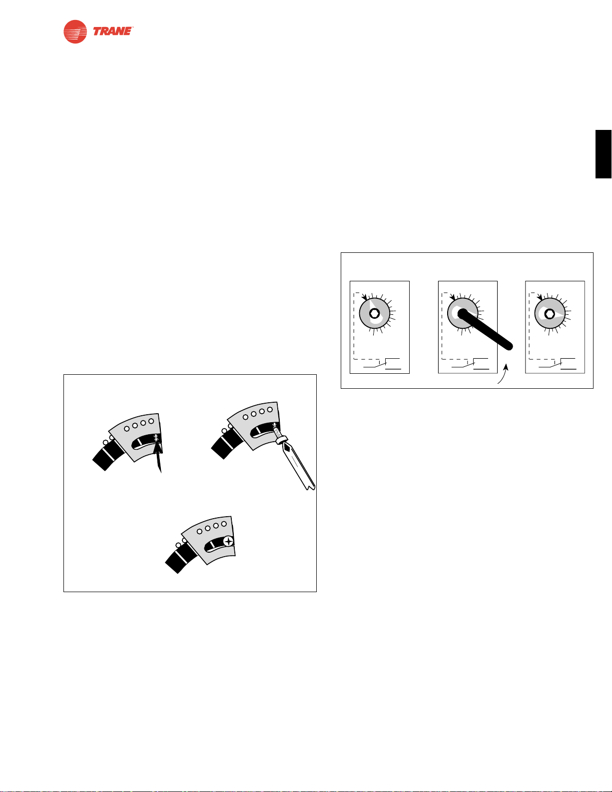
37
I20683 - Subject to change.
TNF
Installation Instructions
Mechanical Installation
Rotation Limitation
The angle of rotation limiter, ZDB-AF2, is used in conjunction
with the tab on the universal clamp or IND-AF2 position
indicator which comes with the ZDB-AF2. In order to function
properly, the clamp or indicator must be mounted correctly.
See Fig. A.
The ZDB-AF2 may not work in certain mounting orientations
using the ZG-106 or ZG-107 mounting brackets. It will not work
with the ZG-108 mounting bracket. Limiting the damper rotation
must be accomplished by adjusting the crank arm linkage.
The ZDB-AF2 may be used to control the rotational output of
the TNF series actuator where a damper has a designed rotation less than 90°. An example would be a 45° or 60° rotating
damper.
Damper Rotation Limiting
1. Determine the amount of damper rotation required.
2. Locate the Angle of Rotation Limiter (ZDB-AF2) on the
actuator so that its edge lines up with the degree graduation on the actuator face which corresponds with the
required rotation. See Figure. C.
3. Find the appropriate cross-hair location through the slot
of the limiter. This is the screw mounting location.
4. Pierce through the label material to allow easy
fastening of the retaining screw.
5. Position the limiter back to the desired position, making
sure the locating “teeth” on the limiter are engaged into
the locating holes on the actuator.
6. Fasten the limiter to the actuator using the self tapping
screw provided.
7. Test the damper rotation before applying power and if
required, a control signal. Re-adjust if necessary.
Auxiliary Switches
The TNF series actuators may be ordered with one built-in
SPDT auxiliary switch used for safety interfacing or signalling,
for example, for fan start-up. The switch position is adjustable
between 5° and 85° of rotation. The crank, supplied with the
actuator, or a 3mm allen wrench is used to adjust the
switching position. See Figure. D.
1 The actuator must be in its fail-safe position.
2. Insert the crank into the hexagon shaped hole located in
the center of the adjustable switch pointer.
3. Rotate the crank until the switch pointer is at the desired
switch point in degrees as shown.
20
30
40
Screw secured at
these cross hairs
20
30
40
Secure angle-ofrotation limiter
Screw
Philips screwdriver
20
30
40
Angle of rotation
is now set at 40°.
Figure C ZDB-AF2 Securing the Angle of Rotation Limiter
Factory setting 5ϒ
Rotate with
crank handle 45ϒ set
5…85ϒ
10
20
30
40
50
60
70
80
5…85ϒ
10
20
30
40
50
60
70
80
5…85ϒ
10
20
30
40
50
60
70
80
C
rank Handle
Figure D
Page 38
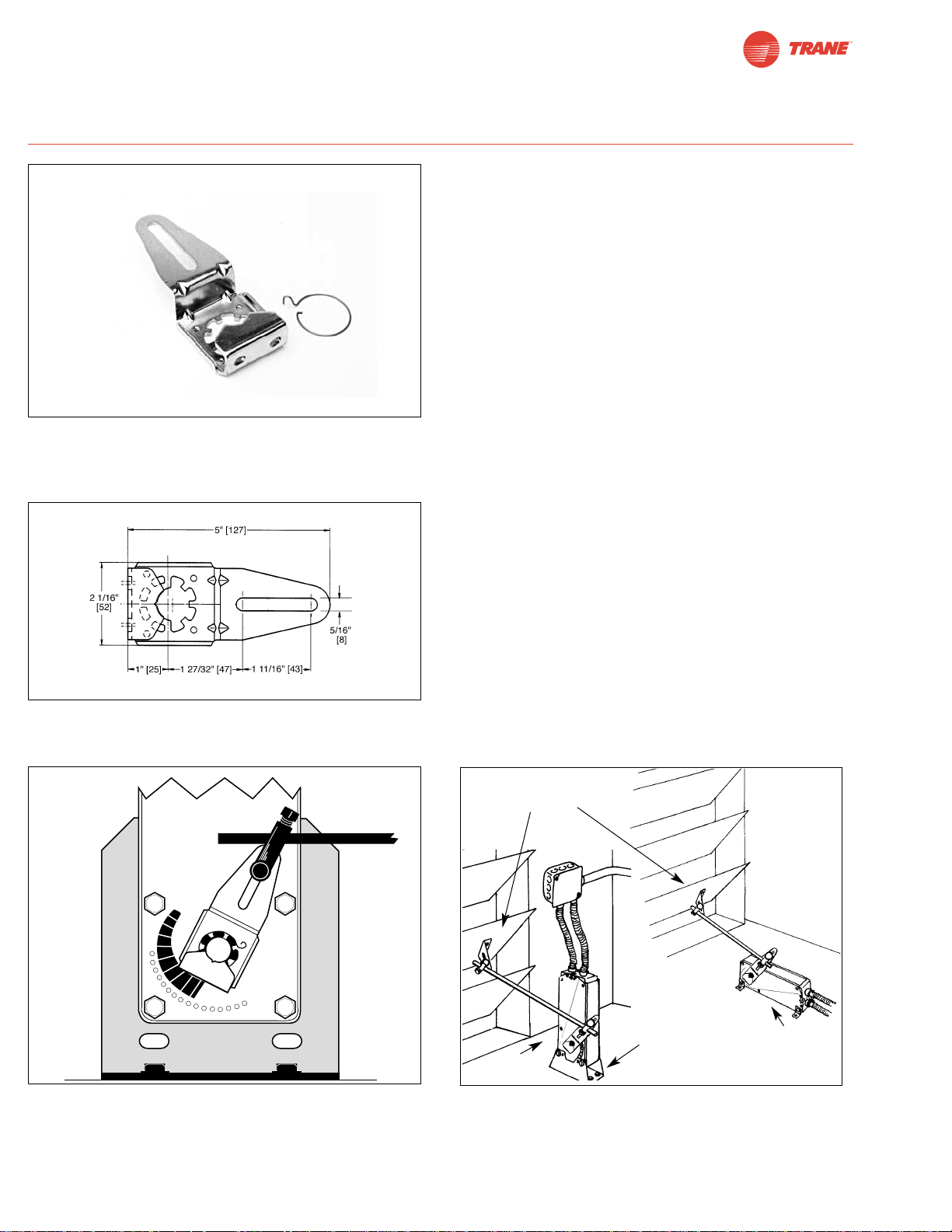
38
I20683 - Subject to change.
Installation Instructions
Non-direct Mounting Methods
KH-AF Non-direct mounting with ZG-108 mounting bracket
Non-direct mounting using various accessories
KH-AF crankarm including retaining ring. Caution: the
retaining clip supplied with the clamp is not used to mount the
KH-AF crankarm.The KH-AF (-1) crankarm is used in non-
direct coupled mounting applications.
Two sizes are available:
KH-AF For round shafts up to 3/4” or square shafts up to 5/8”
KH-AF-1 For jackshafts up to 1.05”
ZG-AF US
Linkage
Kit
KH-AF
Crankarm
ZG-106 or
ZG-107
DC1
Damper Clip
Dimensions [All numbers in brackets are in millimeters.]
Page 39
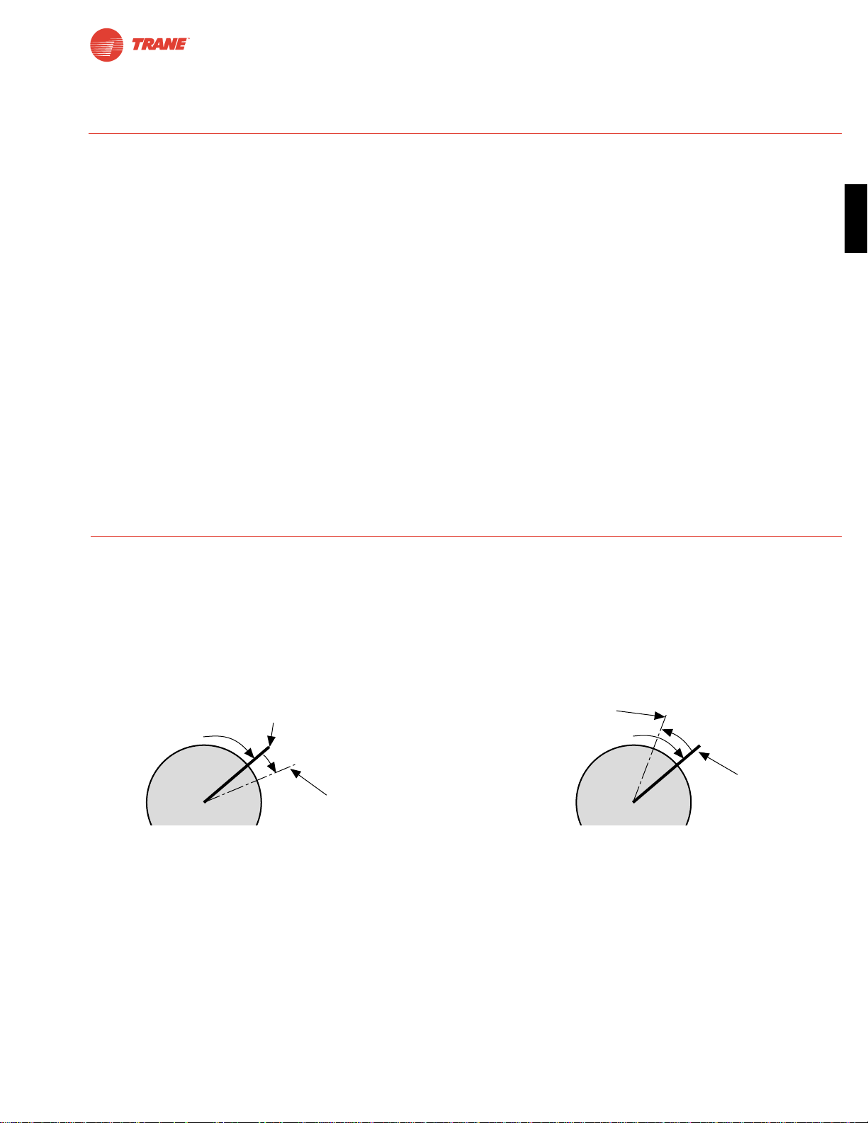
39
I20683 - Subject to change.
TNF
Installation Instructions
Initialization of the TNF24-SR
When power is initially applied, the microprocessor recognizes
that the actuator is at full fail-safe and uses this position as
the base for all of its position calculations. The microprocessor
will retain the initialized zero during short power failures of up
to 20 seconds. For power failures greater than 20 seconds the
actuator would naturally return to it full fail-safe position prior
to the microprocessor losing its memory. When power is
applied again, the actuator will re-initialize the zero position.
The microprocessor will keep count of these short power
failures until 16 occur. At this point, the microprocessor will
automatically drive the actuator to its zero position and
re-initialize to correct for any possible error accumulation.
Motor Position Detection
A brushless DC motors eliminate the need for potentiometers for
positioning. Inside the motor are three “Hall Effect” sensors.
These sensors detect the spinning rotor and send pulses to the
microprocessor which counts the pulses and calculates the position to within 1/3 of a revolution of the motor.
Overload Protection
The TNF24-SR actuators are protected from overload at all
angles of rotation. The on board microprocessor constantly
monitors the rotation of the DC drive motor inside the actuator
and stops the pulses to the motor when it senses a stall condition. The DC motor remains energized and produces full
rated torque to the load. This helps ensure that dampers are
fully closed and that edge and blade seals are always properly
compressed.
Brushless DC Motor Operation
The brushless DC motor spins by reversing the poles of stationary electromagnets housed inside rotating permanent
magnets. The electromagnetic poles are switched by a microprocessor and a special ASIC (Application Specific Integrated
Circuit). Unlike the conventional DC motor, there are no
brushes to wear or commutators to foul.
Additional Operational Information for TNF24-SR Proportional Actuators
Satisfied
Control Position
Satisfied
Control Position
Minimum
Control Resolution
Minimum Reversed
Control Deadband
Prior to Normal Control
80 mV
200 mV
TNF actuator responds to a 80 mV signal
when not changing direction from stop.
TNF actuator responds to a 200 mV signal
when reversing direction from stop position.
TNF24-SR actuators have built-in brushless DC motors which provide better accuracy and longer service life.
The TNF24-SR actuators are designed with a unique non-symmetrical deadband. The actuator follows an increasing or
decreasing control signal with a 80 mV resolution. If the signal changes in the opposite direction, the actuator will not respond
until the control signal changes by 200 mV. This allows these actuators to track even the slightest deviation very accurately,
yet allowing the actuator to “wait” for a much larger change in control signal due to control signal instability.
Control Accuracy and Stability
Page 40

40
I20683 - Subject to change.
WARNING The wiring technician must be trained and
experienced with electronic circuits. Disconnect power supply
before attempting any wiring connections or changes. Make
all connections in accordance with wiring diagrams and follow
all applicable local and national codes. Provide disconnect
and overload protection as required. Use copper, twisted pair,
conductors only. If using electrical conduit, the attachment to
the actuator must be made with flexible conduit.
Always read the controller manufacturer's installation
literature carefully before making any connections. Follow
all instructions in this literature. If you have any questions,
contact the controller manufacturer.
Transformer(s)
The TNF24 . . actuator requires a 24 VAC class 2 transformer
and draws a maximum of 10 VA per actuator. The actuator
enclosure cannot be opened in the field, there are no parts or
components to be replaced or repaired.
– EMC directive: 89/336/EEC
– Software class A: Mode of operation type 1
– Low voltage directive: 73/23/EEC
CAUTION: It is good practice to power electronic or digital
controllers from a separate power transformer than that
used for actuators or other end devices. The power supply
design in our actuators and other end devices use half wave
rectification. Some controllers use full wave rectification.
When these two different types of power supplies are
connected to the same power transformer and the DC commons are connected together, a short circuit is created across
one of the diodes in the full wave power supply, damaging the
controller. Only use a single power transformer to power the
controller and actuator if you know the controller power supply
uses half wave rectification.
Multiple Actuators, One Transformer
Multiple actuators may be powered from one transformer
provided the following rules are followed:
1. The TOTAL current draw of the actuators (VA rating) is
less than or equal to the rating of the transformer.
2. Polarity on the secondary of the transformer is strictly
followed. This means that all No. 1 wires from all
actuators are connected to the common leg on the
transformer and all No 2 wires from all actuators are
connected to the hotleg. Mixing wire No. 1 & 2 on one leg
of the transformer will result in erratic operation or failure
of the actuator and/or controls.
Multiple Actuators, Multiple Transformers
Multiple actuators positioned by the same control signal may
be powered from multiple transformers provided the following
rules are followed:
1. The transformers are properly sized.
2. All No. 1 wires from all actuators are tied together and tied
to the negative leg of the control signal. See wiring
diagram page 19.
Wire Length for TNF… Actuators
Keep power wire runs below the lengths listed in the table in
Figure E. If more than one actuator is powered from the same
wire run, divide the allowable wire length by the number of
actuators to determine the maximum run to any single actuator.
Example for TNF24-SR:
3 actuators, 16 Ga wire
550 ft ÷ 3 actuators = 183 ft. maximum wire run
Maximum wire length:
Wire Size Max. Feet. Wire Size Max. Feet
12 Ga 1100 Ft. 18 Ga 260 Ft.
14 Ga 700 Ft. 20 Ga 140 Ft.
16 Ga 440 Ft. 22 Ga 75 Ft.
Figure E
Wire Type and Wire Installation Tips
For most installations, 18 or 16 Ga. cable works well with the
TNF24… actuators. Use code-approved wire nuts, terminal
strips or solderless connectors where wires are joined. It is
good practice to run control wires unspliced from the actuator
to the controller. If splices are unavoidable, make sure the
splice can be reached for possible maintenance. Tape and/or
wire-tie the splice to reduce the possibility of the splice being
inadvertently pulled apart.
The TNF24… proportional actuators have a digital circuit that
is designed to ignore most unwanted input signals (pickup). In
some situations the pickup may be severe enough to cause
erratic running of the actuator. For example, a large inductive
load (high voltage AC wires, motors, etc.) running near the
power or control wiring may cause excessive pickup. To solve
this problem, make one or more of the following changes:
1. Run the wire in metallic conduit.
2. Re-route the wiring away from the source of pickup.
3. Use shielded wire (Belden 8760 or equal). Ground the
shield to an earth ground. Do not connect it to the
actuator common.
Wire Size Max. Feet. Wire Size Max. Feet
12 Ga 1500 Ft. 18 Ga 375 Ft.
14 Ga 925 Ft. 20 Ga 200 Ft.
16 Ga 550 Ft. 22 Ga 100 Ft.
Installation Instructions
General Wiring
General Wiring Instructions
TNF24 (-S)
TNF24-SR
Page 41

41
I20683 - Subject to change.
TNF
Startup and Checkout
Instructions For TNF24-SR + P-100…
Procedure
Control signal is applied to actuator.
Check power wiring. Correct any
problems. See Note 1.
Turn reversing switch to the correct
position. Make sure the switch is
turned all the way left or right.
Make sure the control signal positive
(+) is connected to Wire No 3 and
control signal negative (-) is connected to wire No. 1. Most control problems are caused by reversing these
two wires. Verify that the reversing
switch is all the way CCW or CW.
Check input signal with a digital volt
meter (DVM). Make sure the input is
within the range of the actuator. For
TNF24-SR this is 2 to 10 VDC or
4 to 20 mA. Note: The input signal
must be above the 2 VDC or 4 mA to
have the actuator move.
Loosen the nuts on the V-bolt and
move the damper by hand from fully
closed to fully open.
Check damper torque requirement.
Actuator works properly. Test
controller by following controller
manufacturer's instructions.
Expected Response
Actuator will move to its “Control
Signal” position.
Power supply rating should be
≥
the total power requirement of
the actuator(s). Minimum voltage of 19.2 VAC or 21.6 VDC.
Actuator will move to its “Control
Signal” position.
Drives to “Control Signal”
position.
Input voltage or current should
be ±1% of what controller's
adjustment or programming
indicate.
Damper will go from fully closed
to fully open.
Torque requirement is ≤
actuator’s minimum torque.
Gives Expected
Response
Go To Step…
Actuator operates
properly.
Step 8
Power wiring correct-
ed, actuator begins
to drive.
Step 1
Actuator operates
properly.
Step 8
Actuator operates
properly.
Step 8
Controller output
(actuator input) is
correct. Input
Polarity Correct.
Step 6
Damper moves
properly.
Step 7
Defective Actuator.
Replace Actuator.
Does Not Give
Expected Response
Go To Step…
No response at all.
Step 2
Operation is
reversed.
Step 3
Does not drive
toward "Control
Signal Position" .
Step 4
Power wiring
corrected, actuator
still does not drive.
Step 4
Does not drive
toward “Control
Signal Position”.
Step 4
Step 5
Reprogram, adjust
repair or replace
controller as needed.
Step 1
Find cause of damper
jam and repair. Move
damper back to the
fully closed position
and tighten the nuts.
Step 1
Recalculate actuator
requirement and
correct installation.
Step
1.
2.
3.
4.
5.
6.
7.
8.
Note 1 Check that the transformer(s) are sized properly.
• If a common transformer is used, make sure that polarity is observed on the secondary. This means connect all No. 1
wires to one leg of the transformer and all No. 2 wires to the other leg of the transformer.
• If multiple transformers are used with one control signal, make sure all No. 1 wires are tied together and tied to control
signal negative (-).
• Controllers and actuators must have separate 24 VAC/VDC power sources.
TNF24-SR + P-100… Electrical Check-out Procedure
Page 42

42
I20683 - Subject to change.
TLF Series Spring Return Direct Coupled Actuator
Minimum 35 in-lb Torque
● For damper areas up to 8 sq-ft*
TLF Series – AT A Glance
*Based on 4 in-lb/ft2damper torque loading. Parallel blade. No edge seals.
Torque: 35 in-lb ●●●●
Power supply: 24 VAC/DC ●●●●
Control signal: on-off ●●
floating point ●
proportional 2 to 10 VDC ●
Feedback: 2 to 10 VDC ●
Running time motor: <75 sec ●●
150 sec constant ●●
spring: <25 sec ●●●●
External direction of rotation switch ●●
Plenum rated cable, 18 GA ●●
Conduit fitting ●●●●
Appliance cable ●●
Built-in auxiliary switch ●
Installation instructions......(p. 50–54) General wiring ..............(p. 55)
Startup and checkout ........(p. 56)
TLF24 (p. 44)
TLF24-S (p. 44)
TLF24-3 (p. 46)
TLF24-SR (p. 48)
Applications
Cost effective quality and performance
for a range of applications including:
• Classroom Unit Ventilators
• Fan/Coil Units
• VAV Terminal Units
• Economizer Units
• Airhandlers
• Control Dampers
Actuators in bold
have BDCM
©
Page 43
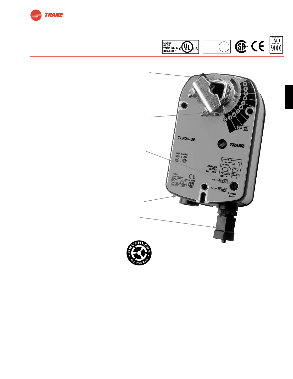
43
I20683 - Subject to change.
TLF
TLF Series Spring Return Direct Coupled Actuator
● Cut labor costs with (10 min. installation) simple direct coupling.
Actuator Centers on 1/2” shaft (K6-1, 3/4” clamp optional).
● True mechanical spring return – the most reliable failsafe.
● Mount for clockwise or counterclockwise fail-safe.
● Easy-to-adjust mechanical stop to limit damper rotation.
● Check damper position easily with clear position indicator.
● Don’t worry about actuator burn-out, it is overload-proof
throughout rotation.
● Need to change control direction?
Do it easily with a simple switch (modulating actuators).
● Built-in auxiliary switch is easy to use, offers feedback
or signal for additional device.
● Microprocessor-controlled brushless DC motor increases
actuator life span and reliability, provides constant running
time (modulating actuators).
● Rugged metal housing withstands rough handling in the
mechanical room.
● 3 ft. cable and conduit connector eases installation.
A CLOSER LOOK…
The T rane Difference
● Low Installation and Life-Cycle Cost.
Easy installation. Accuracy and repeatability.
Low power consumption. No maintenance.
●
Long Service Life.
Components tested before assembly. Every product tested before shipment.
30+ years direct coupled actuator design.
©
LISTED
94D5
TEMP. IND &
REG. EQUIP.
U
L
Page 44
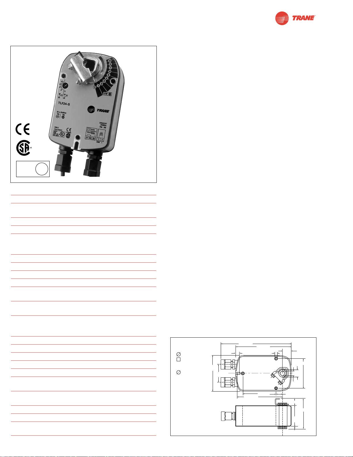
I20683 - Subject to change.
TLF24 (-S)
On-off, Spring Return Fail-Safe, 24 V
Torque min. 35 in-lb, for control of air dampers
Application
For on-off, fail-safe control of dampers in HVAC systems.
Actuator sizing should be done in accordance with the damper
manufacturer’s specifications. Control is on-off from an
auxiliary contact, digital output, or a manual switch.
The actuator is mounted directly to a damper shaft from 3/8”
up to 1/2” in diameter by means of its universal clamp, 1/2”
shaft centered at delivery. For shafts up to 3/4” use K6-1
accessory. A crank arm and several mounting brackets are
available for applications where the actuator cannot be direct
coupled to the damper shaft.
Operation
The TLF series actuators provide true spring return operation
for reliable fail-safe application and positive close off on air tight
dampers. The spring return system provides consistent torque
to the damper with, and without, power applied to the actuator.
The TLF series provides 95° of rotation and is provided with a
graduated position indicator showing 0° to 95°. The actuator
may be stalled anywhere in its normal rotation without the
need of mechanical end switches. Power consumption is
reduced in holding mode.
The TLF24-S version is provided with one built in auxiliary
switch. This SPDT switch is provided for safety interfacing or
signaling, for example, for fan start-up. The switching function
is adjustable between 0° and 95°. The auxiliary switch in the
TLF24-S is double insulated so an electrical ground
connection is not necessary.
For all accessories, see pages 110 and 132.
Dimensions
[All numbers in brackets are in millimeters.]
Technical Data TLF24 (-S)
Power supply 24 VAC ± 20% 50/60 Hz
24 VDC ± 10%
Power consumption running: 5 W; holding: 2.5 W
Transformer sizing 7 VA (class 2 power source)
Electrical connection 3 ft, 18 GA appliance cable
(TLF24-S has 2 cables)
1/2” conduit connector
Overload protection electronic throughout 0° to 95° rotation
Angle of rotation max. 95°, adjust. with mechanical stop
Torque 35 in-lb [4 Nm]
Direction of rotation reversible with cw/ccw mounting
Position indication visual indicator, 0° to 95° (0° is spring
return position)
Auxiliary switch 1 x SPDT 6A (1.5) @ 250 VAC,
UL listed
adjustable 0° to 95° (double insulated)
Running time motor: < 40 to 75 sec
spring: < 25 sec
@-4°F to +122°F [-20°C to +50°C]
< 60 sec
@-22°F [-30°C]
Humidity 5 to 95% RH non-condensing
Ambient temperature -22°F to +122°F [-30°C to +50°C]
Storage temperature -40°F to +176°F [-40°C to +80°C]
Housing NEMA type 2 / IP54
Housing material zinc coated steel
Agency listings UL 873 listed, CSA C22.2 No.24
certified, CE
Noise level max: running < 50 db (A)
spring return 62 dB (A)
Servicing maintenance free
Quality standard ISO 9001
Weight TLF24 3.1 lbs (1.40 kg.)
TLF24-S 3.2 lbs (1.45 kg.)
LISTED
94D5
TEMP. IND &
REG. EQUIP.
U
L
(TLF24-S)
(nominal)
44
D010
Standard:
3/8" to 1/2"
3/8" to 7/16"
Optional
1/2" to 3/4"
w/K6-1
accessory
3.86"
[98]
1.93"
[49]
7.67" [195]
0.39" [10]
4.92" [125]
6.10" [155]
0.256" [6.5]
3.66" [93]
0.98"
[25]
0.71" [18]
0.25" [6.3]
0.79"
[20]
0.5"
[12.7]
0.74" [18.7]
2.24"
[57]
3.15" [80]
3.23" [82]
Page 45
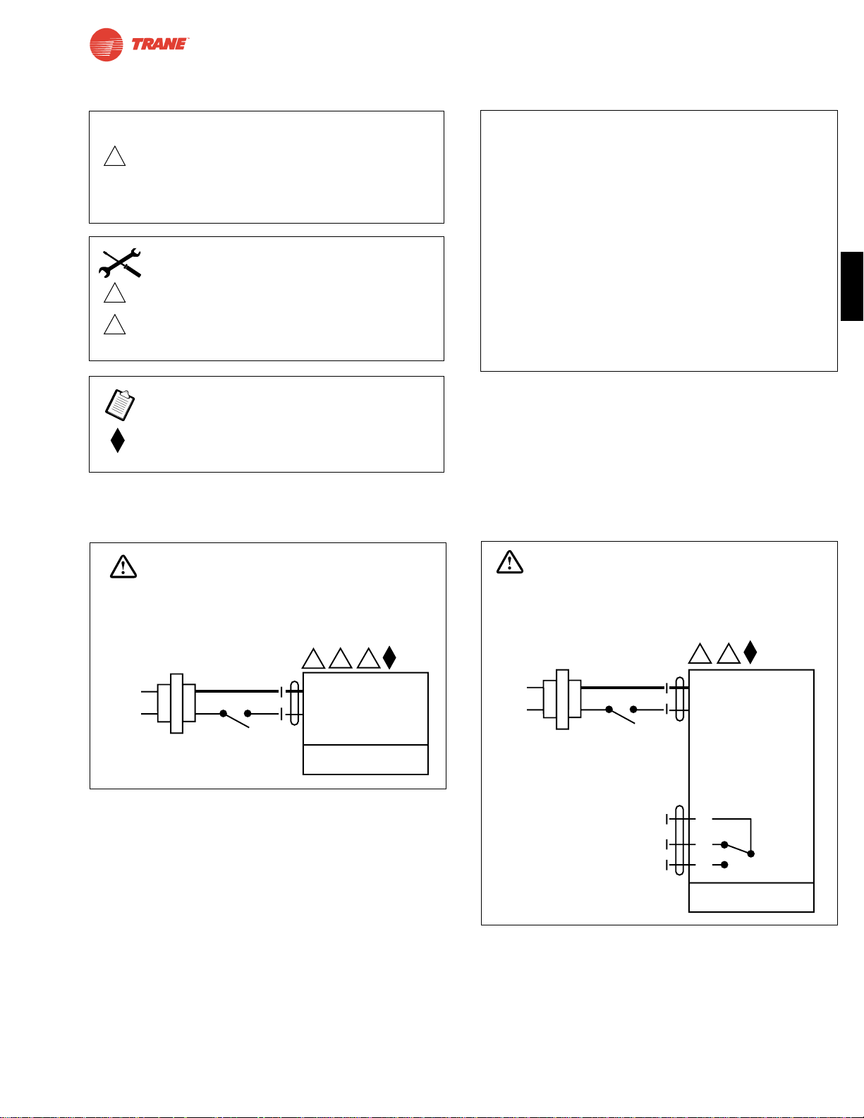
45
I20683 - Subject to change.
TLF
TLF24 (-S)
On-off, Spring Return Fail-Safe, 24 V
Wiring Diagrams
TLF24 (-S) Typical Specification
On-off spring return damper actuators shall be direct
coupled type which require no crankarm and linkage and be
capable of direct mounting to a shaft up to a 3/4” diameter
and center a 1/2” shaft. The actuators must be designed
so that they may be used for either clockwise or
counterclockwise fail-safe operation. Actuators shall be
protected from overload at all angles of rotation. If required,
one SPDT auxiliary switch shall be provided having the
capability of being adjustable. Actuators with auxiliary
switch must be constructed to meet the requirements for
double insulation so an electrical ground is not required to
meet agency listings. Actuators are UL listed and CSA
certified and be manufactured under ISO 9001 International
Quality Control Standards. Actuators shall be as
manufactured by Belimo.
1 Common
2 + Hot
2
24 VAC Transformer
TLF24
Line
Volts
35
WARNING
Live Electrical Components!
During installation, testing, servicing and troubleshooting of this product, it maybe
necessary to work with live electrical components. Have a qualified licensed electrician
or other individual who has been properly trained in handling live electrical components
perform these tasks. Failure to follow all electrical safety precautions when exposed
to live electrical components could result in death or serious injury.
1 Common
2 + Hot
2
24 VAC Transformer
TLF24-S
Line
Volts
3
S1
S2
S3
NC
NO
0° to 95°
WARNING
Live Electrical Components!
During installation, testing, servicing and troubleshooting of this product, it maybe
necessary to work with live electrical components. Have a qualified licensed electrician
or other individual who has been properly trained in handling live electrical components
perform these tasks. Failure to follow all electrical safety precautions when exposed
to live electrical components could result in death or serious injury.
On-off wiring for TLF24
On-off wiring for TLF24-S
W458
W459
2
Equipment damage!
Actuators may be connected in parallel.
Power consumption must be observed and input
impedance must be observed.
3
5
Actuator may also be powered by 24 VDC.
Actuators with plenum rated cable do not have
numbers on wires; use color codes instead.
Actuators with appliance cables use numbers.
Meets cULus or UL and CSA requirements without
the need of an electrical ground connection.
CAUTION
INSTALLATION NOTES
APPLICATION NOTES
Page 46
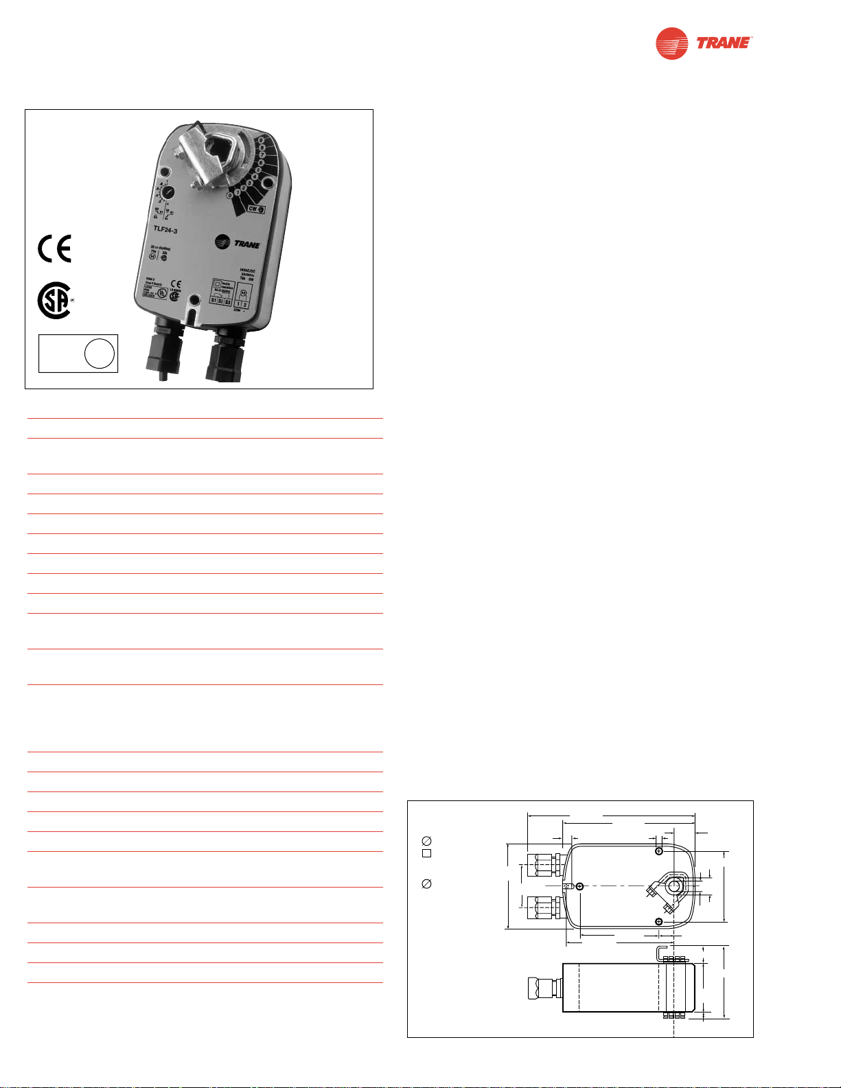
I20683 - Subject to change.
TLF24-3
On-off, Spring Return Fail-Safe, Reversible, Floating Point, 24V
Torque min. 35 in-lb, for control of air dampers
Application
For modulation or on-off control of dampers in HVAC systems.
Actuator sizing should be done in accordance with the damper
manufacturer’s specifications.
The actuator is mounted directly to a damper shaft from 3/8”
up to 1/2” in diameter by means of its universal clamp, 1/2”
shaft centered at delivery. For shafts up to 3/4” use K6-1
accessory. A crank arm and several mounting brackets are
available for applications where the actuator cannot be direct
coupled to the damper shaft.
Control is floating point from a triac or relay, or on-off from an
auxiliary contact from a fan motor contactor, controller, or
manual switch.
Operation
The TLF series actuators provide true spring return operation
for reliable fail-safe application and positive close-off on air tight
dampers. The spring return system provides consistent torque
to the damper with, and without, power applied to the actuator.
The TLF series provides 95° of rotation and is provided with a
graduated position indicator showing 0° to 95°.
The TLF24-3 uses a brushless DC motor which is controlled by
an Application Specific Integrated Circuit (ASIC) and a microprocessor. The microprocessor provides the intelligence to the
ASIC to provide a constant rotation rate. The ASIC monitors
and controls the brushless DC motor’s rotation and provides a
digital rotation sensing function to prevent damage to the actuator in a stall condition. The actuator may be stalled anywhere in
its normal rotation without the need of mechanical end switches.
Power consumption is reduced in holding mode.
For all accessories, see pages 110 and 132.
Dimensions
[All numbers in brackets are in millimeters.]
Technical Data TLF24-3
Power supply 24 VAC ± 20% 50/60 Hz
24 VDC ± 10%
Power consumption running: 2.5 W; holding: 1 W
Transformer sizing 5 VA (class 2 power source)
Electrical connection TLF24-3 3 ft, plenum rated cable
Overload protection electronic throughout 0° to 95° rotation
Input impedance 1000 Ω (0.6w) control inputs
Angle of rotation max. 95°, adjust. with mechanical stop
Torque 35 in-lb [4 Nm]
Direction of rotation spring: reversible with cw/ccw mounting
motor: reversible with built-in switch
Position indication visual indicator, 0° to 95° (0° is spring
return position)
Running time motor: 150 sec constant,
independent of load
spring: < 25 sec
@-4°F to +122°F [-20°C to +50°C]
< 60 sec
@-22°F [-30°C]
Humidity 5 to 95% RH non-condensing
Ambient temperature -22°F to +122°F [-30°C to +50°C]
Storage temperature -40°F to +176°F [-40°C to +80°C]
Housing NEMA type 2 /IP54
Housing material zinc coated metal
Agency listings UL 873 listed; CSA C22.2 No. 24
certified, CE
Noise level max: running < 30 db (A)
spring return 62 dB (A)
Servicing maintenance free
Quality standard ISO 9001
Weight TLF24-3 3.1 lbs (1.40 kg.)
LISTED
94D5
TEMP. IND &
REG. EQUIP.
U
L
46
D010
Standard:
3/8" to 1/2"
3/8" to 7/16"
Optional
1/2" to 3/4"
w/K6-1
accessory
3.86"
[98]
1.93"
[49]
7.67" [195]
0.39" [10]
4.92" [125]
6.10" [155]
0.256" [6.5]
3.66" [93]
0.98"
[25]
0.71" [18]
0.79"
[20]
0.5"
[12.7]
0.74" [18.7]
2.24"
[57]
3.15" [80]
3.23" [82]
0.25" [6.3]
Page 47
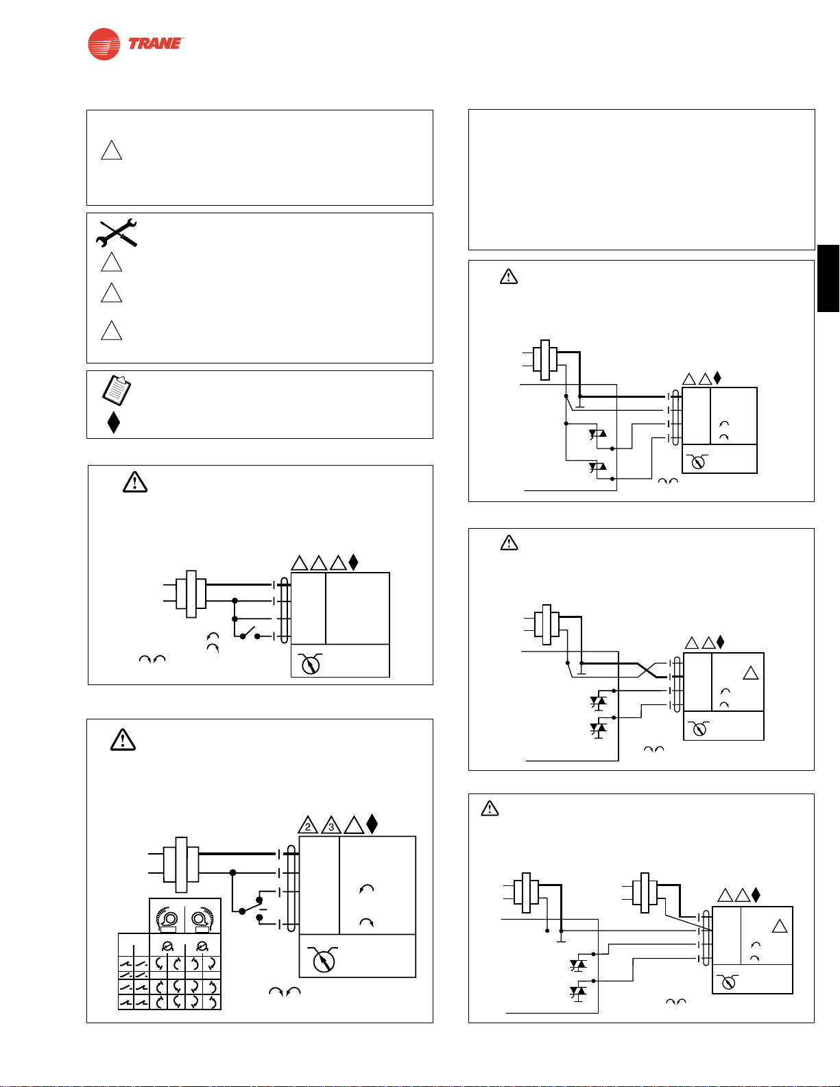
47
I20683 - Subject to change.
TLF
TLF24-3
On-off, Spring Return Fail-Safe, Reversible, Floating Point, 24V
TLF24-3 Typical Specification
Floating point, on-off spring return damper actuators shall be direct coupled
type which require no crankarm and linkage and be capable of direct mounting
to a shaft up to a 3/4” diameter and center a 1/2” shaft. The actuators must be
designed so that they may be used for either clockwise or counterclockwise
fail-safe operation. Actuators shall have an external direction of rotation switch
to reverse control logic. Actuators shall use a brushless DC motor and be
protected from overload at all angles of rotation. Run time shall be constant
and independent of torque. Actuators are UL listed and CSA certified and be
manufactured under ISO 9001 International Quality Control Standards.
Actuators shall be as manufactured by Belimo.
23
5
24 VAC Transformer
a open
a closed
The indication of direction
is valid for switch position CW.
Blk (1) Common
Red (2) +
Wht (3) +
Grn (4) +
TLF24-3
CW CCW
a
Line
Volts
WARNING
Live Electrical Components!
During installation, testing, servicing and troubleshooting of this product, it maybe
necessary to work with live electrical components. Have a qualified licensed electrician
or other individual who has been properly trained in handling live electrical components
perform these tasks. Failure to follow all electrical safety precautions when exposed
to live electrical components could result in death or serious injury.
Line
Volts
The indication of direction
is valid for switch position CW.
Blk (1) Common
Red (2) +
Wht (3) +
Grn (4) +
24 VAC Transformer
TLF24-3
CW CCW
b
CCW
CW
stop
a
(3) (4)
stop stop stop
Installation Side
Direction of Rotation Switch
x
x
x
x
x
x
x
x
x
x
x
x
x
x
x
x
x
x
x
x
x
x
x
x
x
x
x
x
x
x
x
x
x
x
x
x
x
x
CW
CCW
Switch
Positions
CCW
CW
a
b
5
WARNING
Live Electrical Components!
During installation, testing, servicing and troubleshooting of this product, it maybe
necessary to work with live electrical components. Have a qualified licensed electrician
or other individual who has been properly trained in handling live electrical components
perform these tasks. Failure to follow all electrical safety precautions when exposed
to live electrical components could result in death or serious injury.
Wiring Diagrams
On-Off control of TLF24-3
Triac source
Triac sink
Floating point control of TLF24-3
Triac sink with separate transformers
W461
W460
W462
W463W464
3
5
6
Actuator may also be powered by 24 VDC.
Actuators with plenum rated cable do not have
numbers on wires; use color codes instead. Actuators with
appliance cables use numbers.
For triac sink the common connection from the actuator must
be connected to the Hot connection of the controller. The
actuator must be connected to the control board common.
Meets cULus or UL and CSA requirements without the need
of an electrical ground connection.
2
Equipment damage!
Actuators may be connected in parallel.
Power consumption must be observed and input
impedance must be observed.
CAUTION
INSTALLATION NOTES
APPLICATION NOTES
WARNING
Live Electrical Components!
During installation, testing, servicing and troubleshooting of this product, it maybe necessary to work with live
electrical components. Have a qualified licensed electrician or other individual who has been properly trained
in handling live electrical components perform these tasks. Failure to follow all electrical safety precautions
when exposed to live electrical components could result in death or serious injury.
24 VAC Transformer
Line
Volts
2
5
Blk (1) Common
Red
(2) + Hot
Wht
(3) +
(4) +
Grn
CW CCW
TLF24-3
Controller
ComHot
The indication of direction
is valid for switch position CW.
WARNING
Live Electrical Components!
During installation, testing, servicing and troubleshooting of this product, it maybe necessary to work with live
electrical components. Have a qualified licensed electrician or other individual who has been properly trained
in handling live electrical components perform these tasks. Failure to follow all electrical safety precautions
when exposed to live electrical components could result in death or serious injury.
24 VAC Transformer
Line
Volts
5
2
Blk (1) Common
Red
(2) + Hot
Wht
(3) +
(4) +
Grn
CW CCW
TLF24-3
6
Controller
ComHot
The indication of direction
is valid for switch position CW.
WARNING
Live Electrical Components!
During installation, testing, servicing and troubleshooting of this product, it maybe necessary to work with live electrical components.
Have a qualified licensed electrician or other individual who has been properly trained in handling live electrical components
perform these tasks. Failure to follow all electrical safety precautions when exposed to live electrical components could result
in death or serious injury.
24 VAC Transformer
Line
Volts
Controller
ComHot
24 VAC Transformer
Line
Volts
2
5
Blk (1) Common
Red
(2) + Hot
Wht
(3) +
(4) +
Grn
CW CCW
TLF24-3
The indication of direction
is valid for switch position CW.
6
Page 48
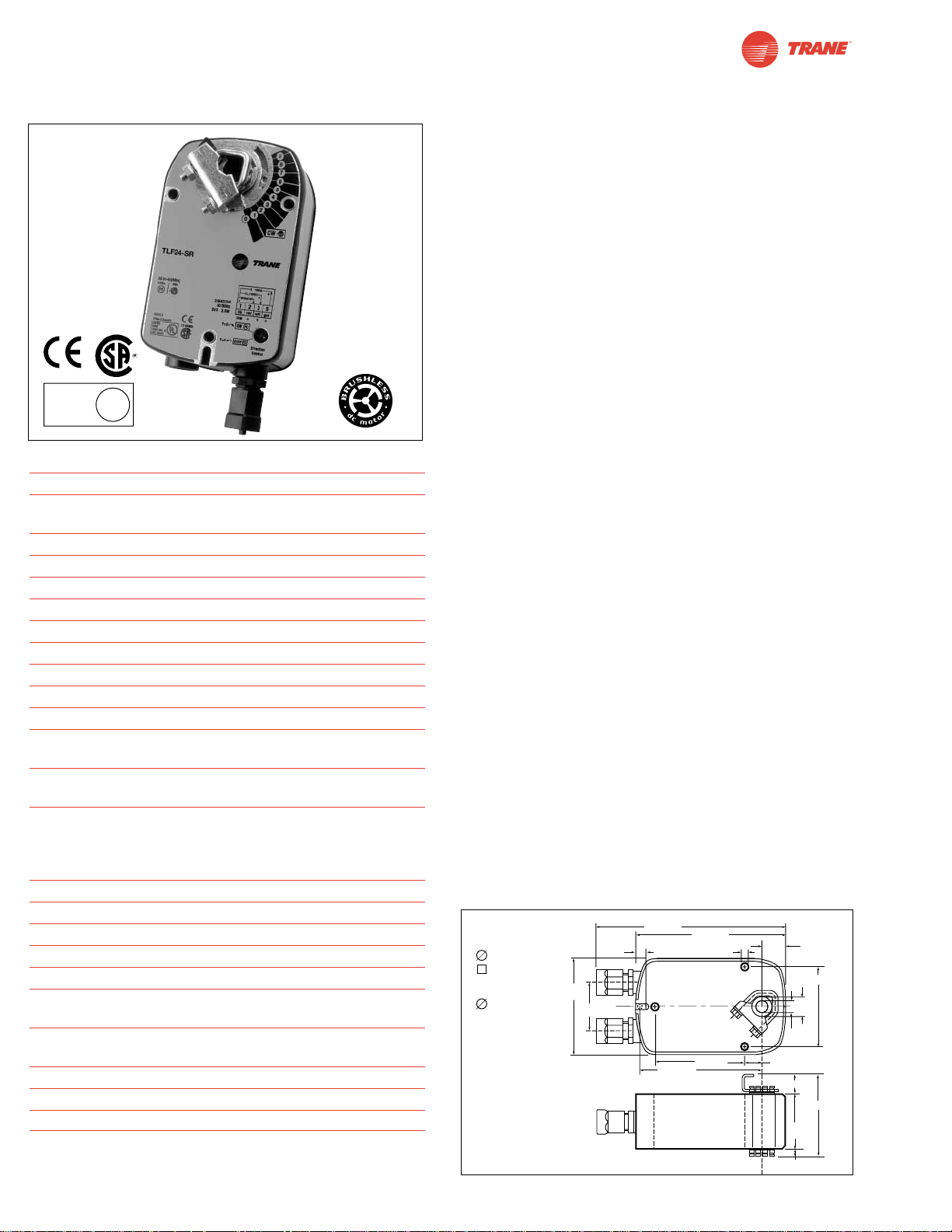
I20683 - Subject to change.
Torque min. 35 in-lb, for control of air dampers
Application
For proportional modulation of dampers in HVAC systems.
Actuator sizing should be done in accordance with the damper
manufacturer’s specifications.
The actuator is mounted directly to a damper shaft from 3/8”
up to 1/2” in diameter by means of its universal clamp, 1/2”
shaft centered at delivery. For shafts up to 3/4” use K6-1
accessory. A crank arm and several mounting brackets are
available for applications where the actuator cannot be direct
coupled to the damper shaft.
The actuator operates in response to a 2 to 10 VDC, or with the
addition of a 500Ω resistor, a 4 to 20 mA control input from an
electronic controller or positioner. A 2 to 10 VDC feedback signal
is provided for position indication or master-slave applications.
Operation
The TLF series actuators provide true spring return operation
for reliable fail-safe application and positive close-off on air
tight dampers. The spring return system provides consistent
torque to the damper with, and without, power applied to the
actuator.
The TLF series provides 95° of rotation and is provided with a
graduated position indicator showing 0° to 95°.
The TLF24-SR uses a brushless DC motor which is controlled
by an Application Specific Integrated Circuit (ASIC) and a
microprocessor. The microprocessor provides the intelligence
to the ASIC to provide a constant rotation rate and to know
the actuator’s exact fail-safe position. The ASIC monitors and
controls the brushless DC motor’s rotation and provides a
digital rotation sensing function to prevent damage to the actuator in a stall condition. The actuator may be stalled anywhere
in its normal rotation without the need of mechanical end
switches. Power consumption is reduced in holding mode.
For all accessories, see pages 110 and 132.
Dimensions
[All numbers in brackets are in millimeters.]
TLF24-SR
Proportional Damper Actuator, Spring Return Fail-Safe, 24 V for 2 to 10 VDC, or 4 to 20 mA Control Signal.
Output Signal of 2 to 10 VDC for Position Indication.
Technical Data TLF24-SR
Power supply 24 VAC ± 20% 50/60 Hz
24 VDC ± 10%
Power consumption running: 2.5 W; holding: 1 W
Transformer sizing 5 VA (class 2 power source)
Electrical connection TLF24-SR 3 ft, plenum rated cable
Overload protection electronic throughout 0° to 95° rotation
Operating range Y 2 to 10 VDC, 4 to 20mA
Input impedance 100 kΩ (0.1 mA), 500Ω
Feedback output U 2 to 10 VDC (max. 0.7 mA) for 95°
Angle of rotation max. 95°, adjust. with mechanical stop
Torque 35 in-lb [4 Nm]
Direction of rotation spring: reversible with cw/ccw mounting
motor: reversible with built-in switch
Position indication visual indicator, 0° to 95°
(0° is spring return position)
Running time motor: 150 sec constant,
independent of load
spring:< 25 sec
@-4°F to +122°F [-20°C to +50°C]
< 60 sec
@-22°F [-30°C]
Humidity 5 to 95% RH non-condensing
Ambient temperature -22°F to +122°F [-30°C to +50°C]
Storage temperature -40°F to +176°F [-40°C to +80°C]
Housing NEMA type 2 / IP54
Housing material zinc coated metal
Agency listings UL 873 listed; CSA C22.2
No. 24 certified, CE
Noise level max: running < 30 db (A)
spring return 62 dB (A)
Servicing maintenance free
Quality standard ISO 9001
Weight TLF24-SR 3.1 lbs (1.40 kg.)
LISTED
94D5
TEMP. IND &
REG. EQUIP.
U
L
(nominal)
D010
48
©
Standard:
3/8" to 1/2"
3/8" to 7/16"
Optional
1/2" to 3/4"
w/K6-1
accessory
3.86"
[98]
1.93"
[49]
7.67" [195]
0.39" [10]
4.92" [125]
6.10" [155]
0.256" [6.5]
3.66" [93]
0.98"
[25]
0.71" [18]
0.79"
[20]
0.5"
[12.7]
0.74" [18.7]
2.24"
[57]
3.15" [80]
3.23" [82]
0.25" [6.3]
Page 49
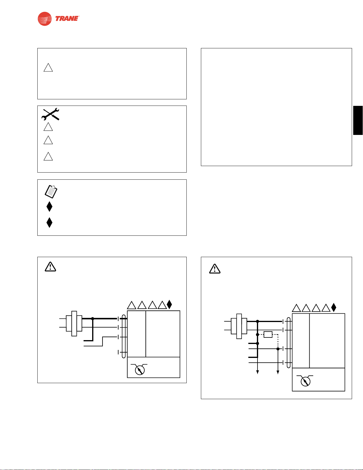
49
I20683 - Subject to change.
TLF
2 to 10 VDC control of TLF24-SR
TLF24-SR
Proportional Damper Actuator, Spring Return Fail-Safe, 24 V for 2 to 10 VDC, or 4 to 20 mA Control Signal.
Output Signal of 2 to 10 VDC for Position Indication.
TLF24-SR Typical Specification
Spring return control damper actuators shall be direct coupled
type which require no crankarm and linkage and be capable of
direct mounting to a shaft up to a 3/4” diameter and center a
1/2” shaft. The actuator must provide proportional damper
control in response to a 2 to 10 VDC or, with the addition
of a 500Ω resistor, a 4 to 20 mA control input from an
electronic controller or positioner.The actuators must be
designed so that they may be used for either clockwise or
counterclockwise fail-safe operation. Actuators shall use a
brushless DC motor controlled by a microprocessor and be
protected from overload at all angles of rotation. Run time
shall be constant, and independent of torque. A 2 to 10 VDC
feedback signal shall be provided for position feedback or
master-slave applications. Actuators are UL listed and CSA
certified and be manufactured under ISO 9001 International
Quality Control Standards. Actuators shall be
as manufactured by Belimo.
Wiring Diagrams
1
6
5
2
3
24 VAC Transformer
Blk (1) Common
Red (2) + Hot
Wht (3) Y Input, 2 to 10V
Grn (5) U Output, 2 to 10V
TLF24-SR
Line
Volts
2 to 10 VDC
Control Signal
(–)
(+)
CW CCW
WARNING
Live Electrical Components!
During installation, testing, servicing and troubleshooting of this product, it maybe
necessary to work with live electrical components. Have a qualified licensed electrician
or other individual who has been properly trained in handling live electrical components
perform these tasks. Failure to follow all electrical safety precautions when exposed
to live electrical components could result in death or serious injury.
To other
actuators
6
3
5
24 VAC Transformer
Blk (1) Common
Red (2) + Hot
Wht (3) Y Input, 2 to 10V
Grn (5) U Output, 2 to 10V
4 to 20 mA
Control Signal
(–)
(+)
2 to 10 VDC
Feedback Signal
(–)
(+)
Ω
500Ω
2
TLF24-SR
CW CCW
Line
Volts
1
WARNING
Live Electrical Components!
During installation, testing, servicing and troubleshooting of this product, it maybe
necessary to work with live electrical components. Have a qualified licensed electrician
or other individual who has been properly trained in handling live electrical components
perform these tasks. Failure to follow all electrical safety precautions when exposed
to live electrical components could result in death or serious injury.
4 to 20 mA control of TLF24-SR with 2 to 10 VDC
feedback output
W465
W466
2
Equipment damage!
Up to 4 actuators may be connected in parallel.
With 4 actuators wired to one 500Ω resistor.
Power consumption must be observed and input
impedance must be observed.
Meets cULus or UL and CSA requirements without
the need of an electrical ground connection.
The ZG-R01 500Ω resistor converts the 4 to 20 mA
control signal to 2 to 10 VDC.
3
5
6
Actuator may also be powered by 24 VDC.
Actuators with plenum rated cable do not have
numbers on wires; use color codes instead.
Actuators with appliance cables use numbers.
Only connect common to neg. (—) leg of control
circuits. The TLF24-SR wire 5 is white.
CAUTION
INSTALLATION NOTES
APPLICATION NOTES
Page 50
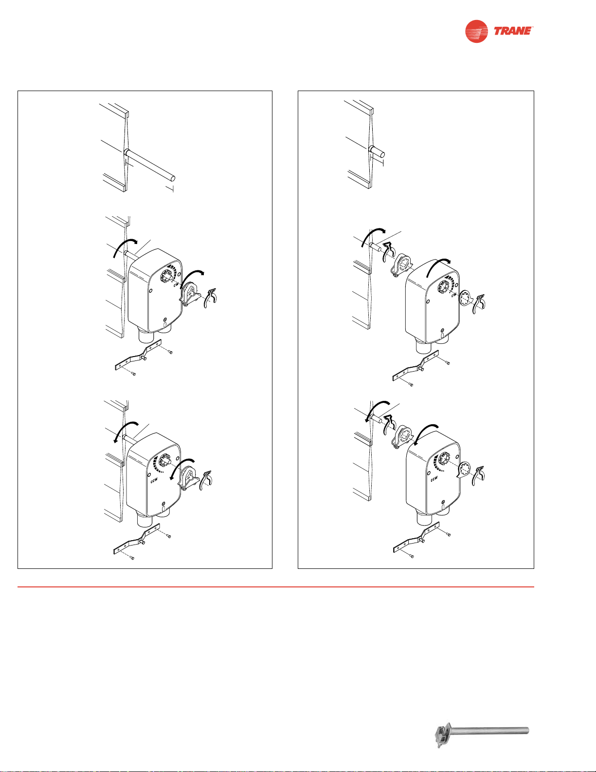
min 3 1/2”
[90]
min 3 1/2”
[90]
min 3/4”
[20]
IND-LF Position Indicator
(optional)
min 3/4”
[20]
IND-LF Position Indicator
(optional)
m
in 3 1/2”
[90]
min 3/4”
[20]
50
I20683 - Subject to change.
Preliminary Steps
1. Actuators should be mounted indoors in dry, relatively
clean environment free from corrosive fumes. If the actuator is to be mounted outdoors, a protective enclosure must
be used to shield the actuator.
2. For new construction work, order dampers with extended
shafts. Instruct the installing contractor to allow space for
mounting and service of the actuator on the shaft.
3. For standard mounting, the damper shaft must extend at least
3 1/2" from the duct. If the shaft extends less than 3 1/2", the
actuator may be mounted in its short shaft configuration. If an
obstruction blocks access, the shaft can be extended with the
AV 10-18 shaft extension
(K6-1 is required).
Installation Instructions
Quick-Mount Visual Instructions
1. Rotate the damper to its failsafe position. If the shaft rotates
counterclockwise, mount the “CCW” side of the actuator out. If it
rotates clockwise, mount the actuator with the “CW” side out.
2. If the universal clamp is not on the correct side of the
actuator, move it to the correct side.
3. Slide the actuator onto the shaft and tighten the nuts on the
V-bolt with a 10 mm wrench to 6-8 ft-lb of torque.
4. Slide the anti-rotation strap under the actuator so that it
engages the slot at the base of the actuator. Secure the
strap to the duct work with #8 self-tapping screws.
NOTE: Read the “Standard Mounting” instructions, on the next
page, for more detailed information.
Standard
Mounting
Short Shaft
Mounting
Dimensions
[All numbers in brackets are in millimeters.]
Quick-Mount Visual Instructions
Page 51
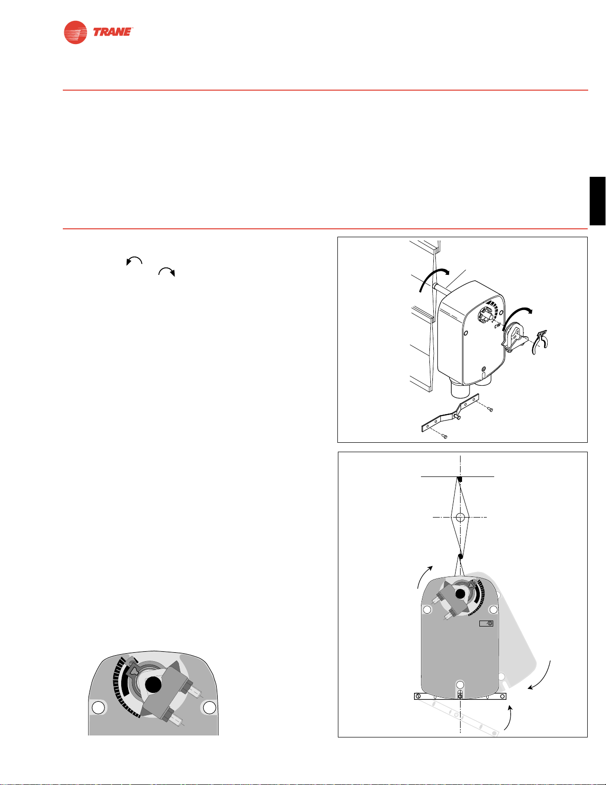
51
I20683 - Subject to change.
TLF
1. See Figue. B. Manually move the damper to the fail-safe
position (a) (usually closed). If the shaft rotated counterclockwise ( ), this is a CCW installation. If the shaft
rotated clockwise ( ), this is a CW installation. In a
left hand installation, the actuator side marked “CW” faces
out, while in a CW installation, the side marked “CCW”
faces out. All other steps are identical.
2. The actuator is usually shipped with the universal clamp
mounted to the “CW” side of the actuator. To test for
adequate shaft length, slide the actuator over the shaft
with the side marked “CW” (or the “CCW” side if this is the
side with the clamp). If the shaft extends at least 1/8”
through the clamp, mount the actuator as follows. If not,
go to the Short Shaft Installation section.
3. If the clamp is not on the correct side as determined in step
#1, re-mount the clamp as follows. If it is on the correct
side, proceed to step #5. Look at the universal clamp. If
you are mounting the actuator with the “CCW” side out,
position the clamp so that the pointer section of the tab is
pointing to 0° (see Figure. C) and the spline pattern of the
clamp mates with spline of the actuator. Slip the clamp over
the spline. (Use the same procedure if the “CW” side is
out.)
4. Lock the clamp to the actuator using the retaining clip.
5. Verify that the damper is still in its full fail-safe position (a).
6. Mount the spring return actuator to the shaft. Tighten the
universal clamp, finger tight only.
7. Mount the anti-rotation strap at the base of the actuator.
Do not tighten the screws.
8. Remove the screw from one end of the mounting bracket
and pivot it away from the actuator.
9. Loosen the universal clamp and, making sure not to move
the damper shaft, rotate the actuator approximately 5° in
the direction which would open the damper.
10. Tighten the universal clamp to the shaft.
11. Rotate the actuator to apply pressure to the damper seals
(b) and re-engage the anti-rotation strap (c).
12. Tighten all fasteners.
Installation Instructions
Standard Mounting / Airtight Damper Procedure
Mechanical Operation
The actuator is mounted directly to a damper shaft up to 1/2” in diameter by means of its universal clamp, or up to a 3/4” shaft with
the optional K6-1 clamp. A crank arm and several mounting brackets are available for applications where the actuator cannot be
direct coupled to the damper shaft.
The TLF series actuators provide true spring return operation for reliable fail-safe application and positive close-off on air tight
dampers. The spring return system provides consistent torque to the damper with, and without, power applied to the actuator.
The TLF series provides 95° of rotation and is provided with a graduated position indicator showing 0° to 95°.
The TLF…-S versions are provided with one built-in auxiliary switch. This SPDT switch is provided for safety interfacing or
signaling, for example, for fan start-up. The switching function is adjustable between 0° and 95°.
Universal
Clamp
0
.2
.4
.6
.8
1
Figure. B
Figure. C
0
1
2
4
5
6
7
8
9
L
C
b
c
a
.2
.4
.6
.8
1
CW
0
Standard
Mounting
Standard
Mounting
min 3 1/2”
[90]
Page 52
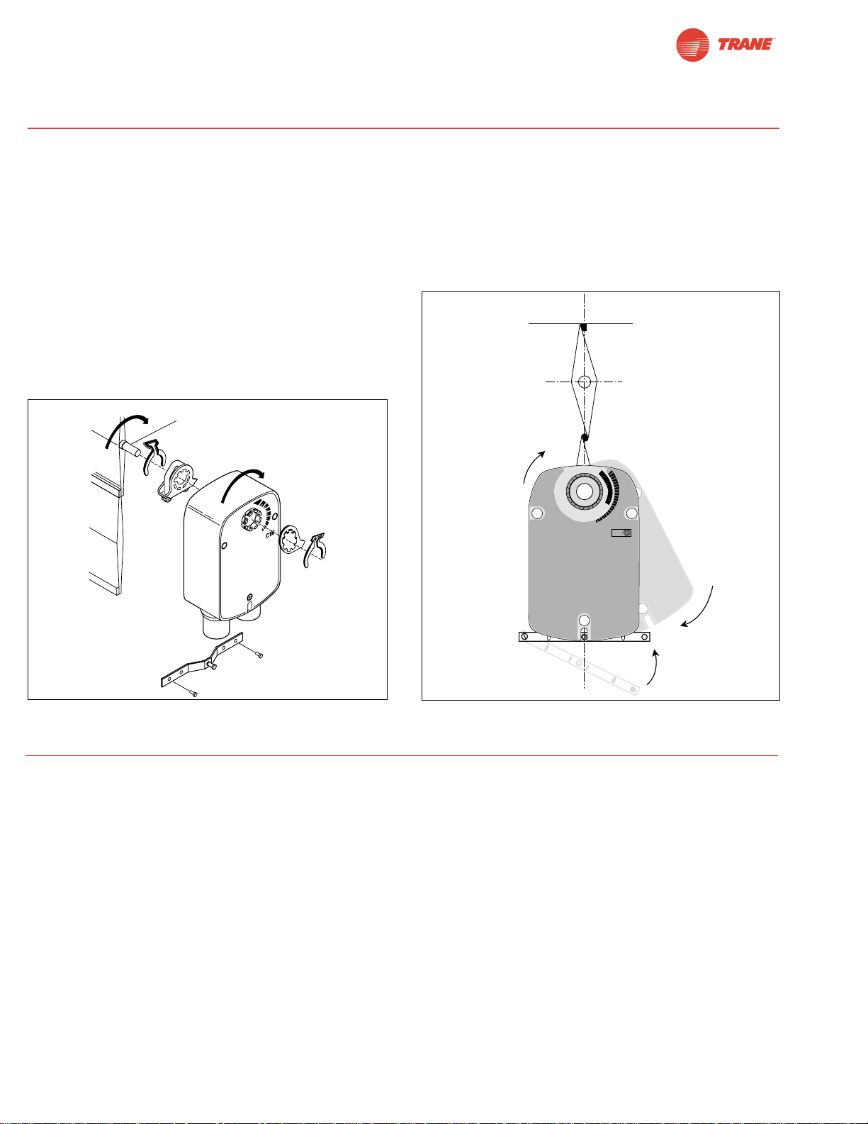
52
I20683 - Subject to change.
If the shaft extends at least 3/4” from the duct, follow these
steps:
1. See Figure D. Move damper blades to the fail-safe position (a).
2. Determine the best orientation for the universal clamp on the
back of the actuator. The best location would be where you
have the easiest access to the V bolt nuts on the clamp.
3. Engage the clamp to the actuator as close as possible to
the determined location.
4. Lock the clamp to the actuator using the retainer clip.
5. Mount the spring return actuator to the shaft. Tighten the
universal clamp, finger tight only.
6. Mount the anti-rotation strap at the base of the actuator. Do
not tighten the screws.
7. Remove the screw from one end of the mounting bracket
and pivot it away from the actuator.
8. Loosen the universal clamp and, making sure not to move
the damper shaft, rotate the actuator approximately 5° in
the direction which would open the damper.
9. Verify that the damper is still in its full fail-safe position.
10. Tighten the universal clamp to the shaft.
11. Rotate the actuator to apply pressure to the damper seals
(b) and re-engage the anti-rotation strap (c).
12. Tighten all fasteners.
13. Use IND-LF accessory if position indication is needed.
Installation Instructions
Short Shaft Mounting with IND-LF Position Indicator / Airtight Damper Procedure
Initialization of the TLF24-SR
When power is applied, the internal microprocessor
recognizes that the actuator is at its full fail-safe position and
uses this position as the base for all of its position calculations. This procedure takes approximately 15 seconds. During
this time you will see no response at the actuator. The microprocessor will retain the initialized zero during short power failures of up to 25 seconds. When power is applied during this
period, the actuator will return to normal operation and proceed to the position corresponding to the input signal provided. For power failures over 25 seconds, the actuator will be at
it fail-safe position and will go through the start up initialization
again.
Motor Position Detection
A Brushless DC motors eliminate the need for potentiometers
for positioning. Inside the motor are three “Hall Effect” sensors. These sensors detect the spinning rotor and send pulses
to the microprocessor which counts the pulses and calculates
the position to within 1/3 of a revolution of the motor.
Overload Protection
The TLF, on-off actuators are electronically protected against
overload. The TLF, On-off actuators have an internal current
limiter which maintains the current at a safe level which will not
damage the actuator while providing adequate holding torque.
The TLF24, modulating actuators (TLF24-SR, TLF24-3) are
protected against overload by digital technology located in the
ASIC. The ASIC circuitry constantly monitors the rotation of the
brushless DC motor inside the actuator and stops the
pulsing to the motor when it senses a stall condition. The motor
remains energized and produces full rated torque during stall
conditions. The actuator will try to move in the direction of the
stall every 2 minutes, for a period of 32 minutes. After this, the
actuator will try again every 2 hours .
Operational Information for TLF24-SR Actuators
min 3/4”
[20]
IND-LF Position Indicator
(optional)
Figure D
0
1
2
4
5
6
7
8
9
L
C
b
c
a
.2
.4
.6
.8
1
CW
0
Short Shaft
Mounting
Short Shaft
Mounting
Page 53
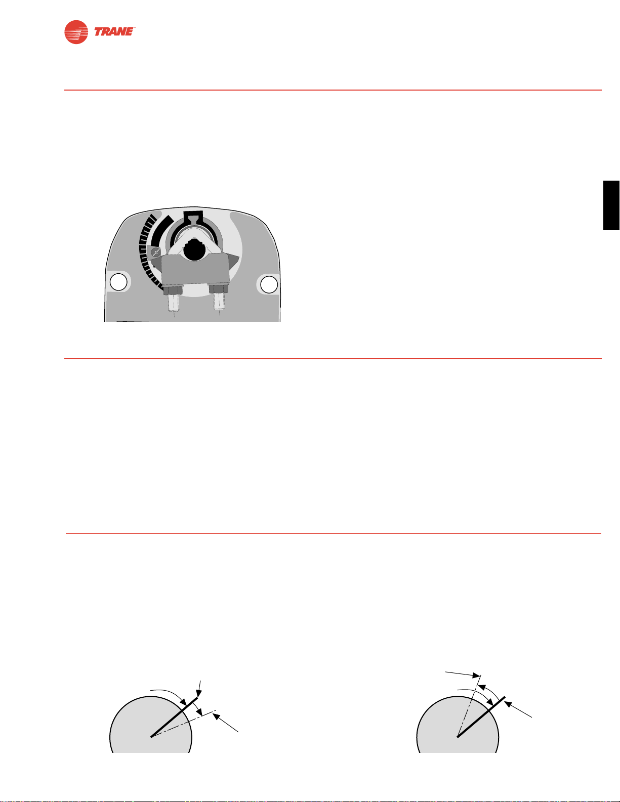
53
I20683 - Subject to change.
TLF
The TLF actuators are provided with an adjustable stop
to limit the rotation of the actuator. This function works in
conjunction with the universal clamp or the optional position
indicator. The adjustable stop is needed when rotation of less
than 95° is required. The TLF actuator can be indefinitely
stalled, in any position, without harming the actuator.
Using the Universal Clamp:
1. Loosen the end stop fastening screw using a #2 Phillips
screwdriver.
2. Move the stop block so the bottom edge of the block lines
up with the number corresponding to the desired degrees
of rotation (example: 45 degrees of rotation = .5).
3. Lock the block in place with the fastening screw.
4. Check the actuator for proper rotation.
Using the IND-LF Position Indicator with Adjustable Stop:
Note: Preferred method if short shaft mounting is used.
1. With the actuator in its fail-safe position, place the IND-LF
position indicator so that it points to the 0° position.
2. Loosen the end stop fastening screw using a #2 Phillips
screwdriver.
3. Move the stop block so the bottom edge of the block lines
up with the number corresponding to the desired degrees
of rotation (example: 45 degrees of rotation = .5).
4. Lock the block in place with the fastening screw.
5. Check the actuator for proper rotation.
0
.2
.4
.6
.8
1
Mechanical Angle of Rotation Limiting
Installation Instructions
Quick-Mount Visual Instructions for Mechanical Installation
TLF24-SR actuators have built-in brushless DC motors which provide better accuracy and longer service life.
The TLF24-SR actuators are designed with a unique non-symmetrical deadband. The actuator follows an increasing or
decreasing control signal with a 80 mV resolution. If the signal changes in the opposite direction, the actuator will not respond
until the control signal changes by 200 mV. This allows these actuators to track even the slightest deviation very accurately,
yet allowing the actuator to “wait” for a much larger change in control signal due to control signal instability.
Control Accuracy and Stability
Satisfied
Control Position
Satisfied
Control Position
Minimum
Control Resolution
Minimum Reversed
Control Deadband
Prior to Normal Control
80 mV
200 mV
TLF actuator responds to a 80 mV signal when
not changing direction from stop position.
TLF actuator responds to a 200 mV signal when
reversing direction from stop position.
TLF24-3 and TLF24-SR actuators have a direction of rotation
switch on the cover labeled “CW-CCW”. Switch position indicates
start point. For the TLF24-SR, with the switch in position “CW”, the
actuator rotates clockwise with a decrease in voltage or current.
With the switch in position “CCW”, the actuator rotates counterclockwise with a decrease in voltage or current.
The TLF24-3 and TLF24-SR actuators rotate clockwise when the
switch is in the “CW” position and power is applied to wire #3.
When power is applied to wire #4 the actuator rotates counter
clockwise.
Rotating the direction of rotation switch to “CCW” reverses the
control logic.
During checkout, the switch position can be temporarily
reversed and the actuator will reverse its direction. This
allows the technician a fast and easy way to check the actuator
operation without having to switch wires or change settings on
the controller. When the check-out is complete, make sure
the switch is placed back to its original position.
Direction of Rotation Switch
Page 54
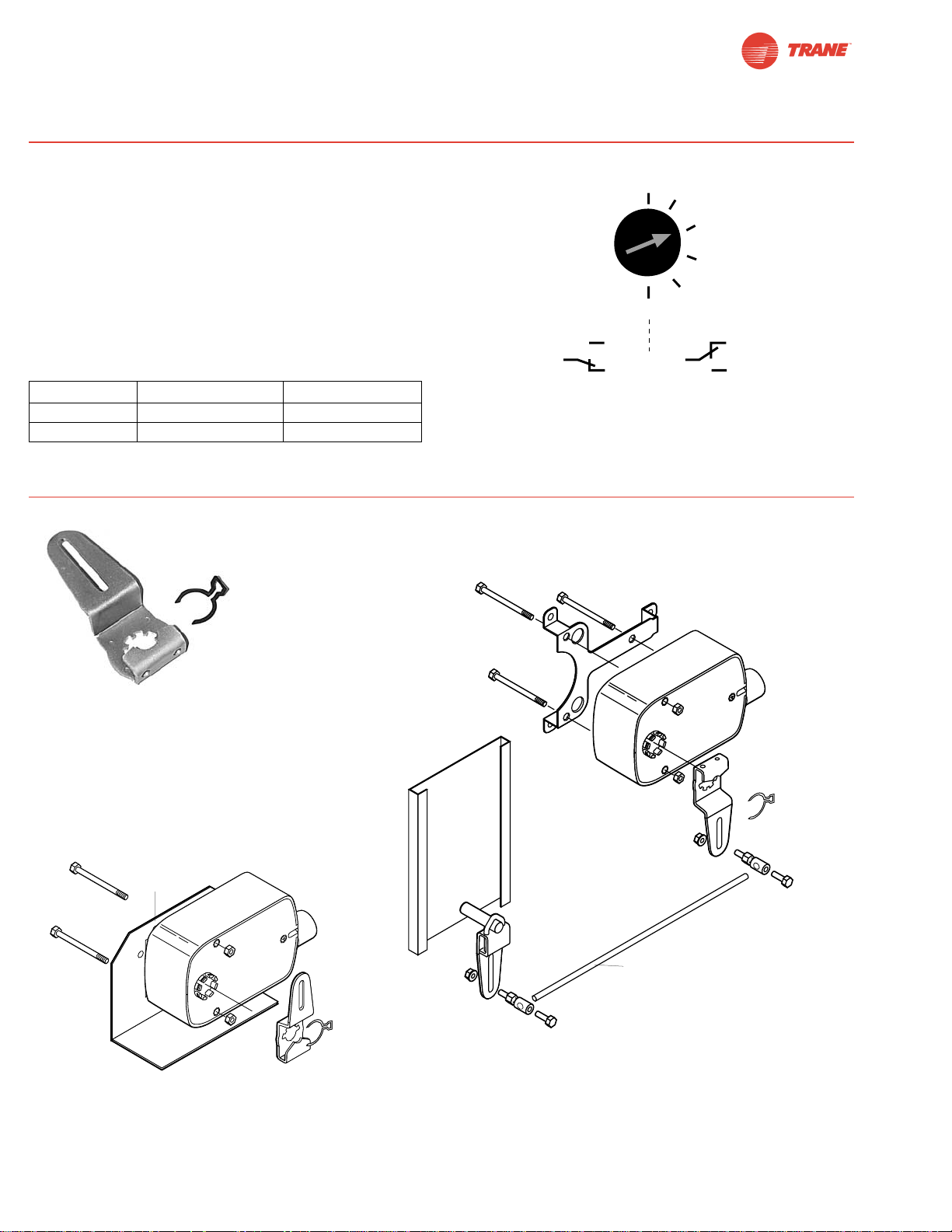
54
I20683 - Subject to change.
Installation Instructions
The …-S model actuators are equipped with an adjustable
auxiliary switch used to indicate damper position or to
interface additional controls or equipment. Switching positions
can be set over the full 0 to 95° rotation simply by setting a
switch on the actuator.
1. Set desired switch position (Example 60%).
2. As the actuator rotates, the switch indicator moves from .6
(60%) toward 0 (0%). When the indicator passes 0 the
switch contact between S1 and S2 is broken and the contact between S1 and S3 is made.
Auxiliary Switches
Non-Direct Mounting Methods
KH-LF Crankarm including retaining ring
KH-LF
For shafts up to 1/2”
ZG-112
(pushrod not supplied with kit)
KG6 ball joint and
universal crankarm
(not included)
KG6 ball joint
(not included)
KH-LF
crankarm
KH-LF
crankarm
ZG-LF2
Crankarm Adaptor Kit
ZG-LF112
Crankarm Adaptor Kit
Voltage Resistive load Inductive load
120 VAC 6 A 3 A
250 VAC 6 A 1.5 A
Switch Rating
S1
S2
S3
1
.8
.6
.4
.2
0
S2
S1
S3
Page 55
55
I20683 - Subject to change.
TLF
WARNING The wiring technician must be trained and experienced with electronic circuits. Disconnect power supply
before attempting any wiring connections or changes. Make
all connections in accordance with wiring diagrams and follow
all applicable local and national codes. Provide disconnect
and overload protection as required. Use copper, twisted pair,
conductors only. If using electrical conduit, the attachment to
the actuator must be made with flexible conduit.
Always read the controller manufacturer's installation
literature carefully before making any connections. Follow
all instructions in this literature. If you have any questions,
contact the controller manufacturer.
Transformer(s)
The TLF24 . . actuator requires a 24 VAC class 2 transformer
and draws a maximum of 7 VA per actuator. The actuator
enclosure cannot be opened in the field, there are no parts or
components to be replaced or repaired.
– EMC directive: 89/336/EEC
– Software class A: Mode of operation type 1
– Low voltage directive: 73/23/EEC
CAUTION: It is good practice to power electronic or digital
controllers from a separate power transformer than that used
for actuators or other end devices. The power supply design
in our actuators and other end devices use half wave rectification. Some controllers use full wave rectification. When these
two different types of power supplies are connected to the
same power transformer and the DC commons are connected
together, a short circuit is created across one of the diodes in
the full wave power supply, damaging the controller. Only use
a single power transformer to power the controller and
actuator if you know the controller power supply uses half
wave rectification.
Multiple Actuators, One Transformer
Multiple actuators may be powered from one transformer
provided the following rules are followed:
1. The TOTAL current draw of the actuators (VA rating) is
less than or equal to the rating of the transformer.
2. Polarity on the secondary of the transformer is strictly followed. This means that all No. 1 wires from all actuators
are connected to the common leg on the transformer and
all No 2 wires from all actuators are connected to the hotleg. Mixing wire No. 1 & 2 on one leg of the transformer
will result in erratic operation or failure of the actuator
and/or controls.
Multiple Actuators, Multiple Transformers
Multiple actuators positioned by the same control signal may
be powered from multiple transformers provided the following
rules are followed:
1. The transformers are properly sized.
2. All No. 1 wires from all actuators are tied together and tied
to the negative leg of the control signal. See wiring diagram.
Wire Length for TLF… Actuators
Keep power wire runs below the lengths listed in the table in
Figure A. If more than one actuator is powered from the same
wire run, divide the allowable wire length by the number of
actuators to determine the maximum run to any single actuator.
Example for TLF24-SR:
3 actuators, 16 Ga wire
550 ft ÷ 3 actuators = 183 ft. maximum wire run
Maximum Wire Length:
Wire Size Max. Feet. Wire Size Max. Feet
12 Ga 1100 Ft. 18 Ga 260 Ft.
14 Ga 700 Ft. 20 Ga 140 Ft.
16 Ga 440 Ft. 22 Ga 75 Ft.
Figure A
Wire Type and Wire Installation Tips
For most installations, 18 or 16 Ga. cable works well with the
TLF24… actuators. Use code-approved wire nuts, terminal
strips or solderless connectors where wires are joined. It is
good practice to run control wires unspliced from the actuator
to the controller. If splices are unavoidable, make sure the
splice can be reached for possible maintenance. Tape and/or
wire-tie the splice to reduce the possibility of the splice being
inadvertently pulled apart.
The TLF24… proportional actuators have a digital circuit that is
designed to ignore most unwanted input signals (pickup). In
some situations the pickup may be severe enough to cause
erratic running of the actuator. For example, a large inductive
load (high voltage AC wires, motors, etc.) running near the
power or control wiring may cause excessive pickup. To solve
this problem, make one or more of the following changes:
1. Run the wire in metallic conduit.
2. Re-route the wiring away from the source of pickup.
3. Use shielded wire (Belden 8760 or equal). Ground the
shield to an earth ground. Do not connect it to the
actuator common.
Brushless DC Motor Operation
The brushless DC motor spins by reversing the poles of
stationary electromagnets housed inside rotating permanent
magnets. The electromagnetic poles are switched by a
microprocessor and a special ASIC (Application Specific
Integrated Circuit). Unlike the conventional DC motor, there
are no brushes to wear or commutators to foul.
Installation Instructions
General Wiring
TLF24 (-S)
TLF24-SR / TLF24-3
Wire Size Max. Feet. Wire Size Max. Feet
12 Ga 1500 Ft. 18 Ga 375 Ft.
14 Ga 925 Ft. 20 Ga 200 Ft.
16 Ga 550 Ft. 22 Ga 100 Ft.
Page 56

56
I20683 - Subject to change.
Startup and Checkout
Instructions For TLF24-SR + P100
Procedure
Remove power to reset actuator.
Re-apply power.
Apply control signal to actuator.
Check power wiring. Correct any
problems. See Note 1.
Turn reversing switch to the correct
position. Make sure the switch is
turned all the way left or right.
Make sure the control signal positive
(+) is connected to Wire No 3 and
control signal negative (-) is connected to wire No. 1. Most control problems are caused by reversing these
two wires. Verify that the reversing
switch is all the way CCW or CW.
Check input signal with a digital volt
meter (DVM). Make sure the input is
within the range of the actuator. For
TLF24-SR this is 2 to 10 VDC or
4 to 20 mA. Note: The input signal
must be above the 2 VDC or 4 mA to
have the actuator move.
Loosen the nuts on the V-bolt and
move the damper by hand from fully
closed to fully open.
Check damper torque requirement.
Actuator works properly. Test
controller by following controller
manufacturer's instructions.
Expected Response
Actuator will move to its “Control
Signal” position.
Power supply rating should be
≥
the total power requirement of
the actuator(s). Minimum voltage of 19.2 VAC or 21.6 VDC.
Actuator will move to its “Control
Signal” position.
Drives to “Control Signal”
position.
Input voltage or current should be
±1% of what controller's adjustment or programming indicate.
Damper will go from fully closed
to fully open.
Torque requirement is ≤
actuator’s minimum torque.
Gives Expected
Response
Go To Step…
Actuator operates
properly.
Step 8
Power wiring correct-
ed, actuator begins
to drive.
Step 1
Actuator operates
properly.
Step 8
Actuator operates
properly.
Step 8
Controller output
(actuator input) is
correct. Input
Polarity Correct.
Step 6
Damper moves
properly.
Step 7
Defective Actuator.
Replace Actuator.
Does Not Give
Expected Response
Go To Step…
No response at all.
Step 2
Operation is
reversed.
Step 3
Does not drive
toward "Control
Signal Position".
Step 4
Power wiring
corrected, actuator
still does not drive.
Step 4
Does not drive
toward “Control
Signal Position”.
Step 4
Step 5
Reprogram, adjust
repair or replace
controller as needed.
Step 1
Find cause of damper
jam and repair. Move
damper back to the
fully closed position
and tighten the nuts.
Step 1
Recalculate actuator
requirement and
correct installation.
Step
1.
2.
3.
4.
5.
6.
7.
8.
Note 1 Check that the transformer(s) are sized properly.
• If a common transformer is used, make sure that polarity is observed on the secondary. This means connect all No. 1
wires to one leg of the transformer and all No. 2 wires to the other leg of the transformer.
• If multiple transformers are used with one control signal, make sure all No. 1 wires are tied together and tied to control
signal negative (-).
• Controllers and actuators must have separate 24 VAC/VDC power sources.
TLF24-SR + P100 Electrical Check-out Procedure
Page 57

57
I20683 - Subject to change.
TLF
Notes/Work Pad
Page 58
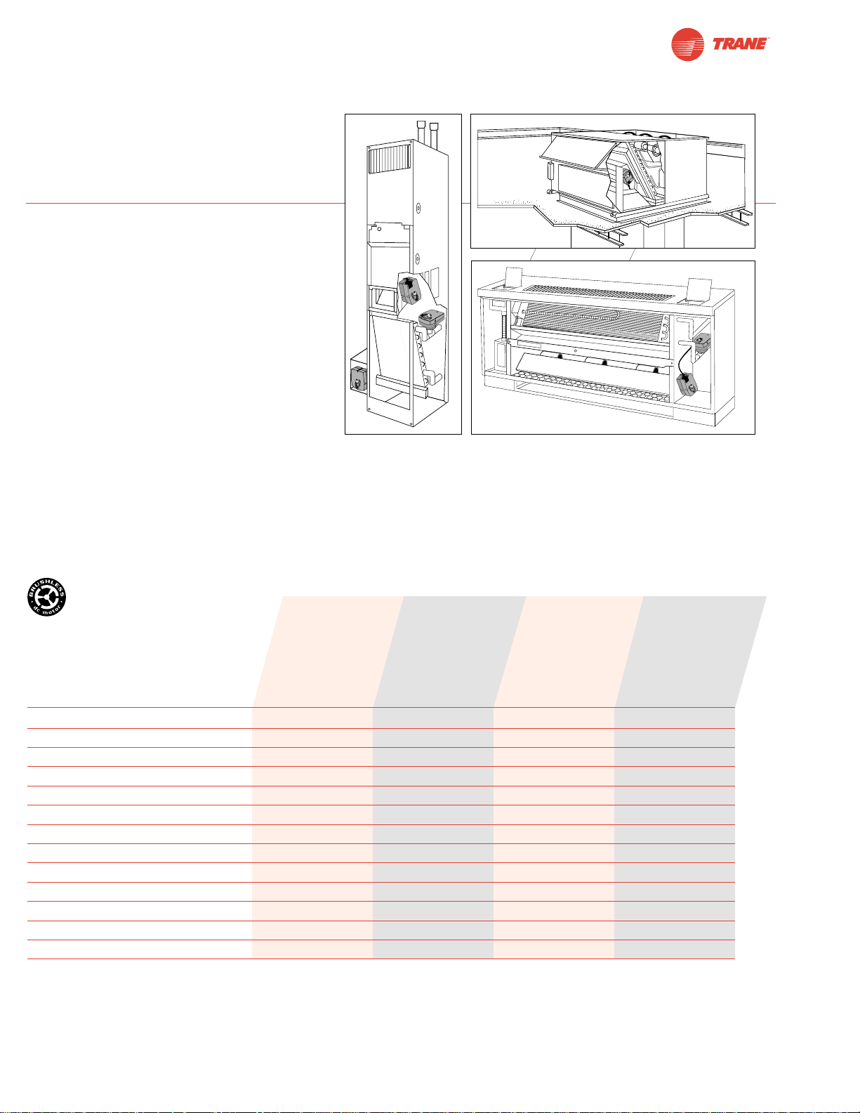
58
I20683 - Subject to change.
TTF Series Spring Return Direct Coupled Actuator
Minimum 18 in-lb Torque
● For damper areas up to 4.5 sq-ft*
TTF Series – AT A Glance
Torque: 18 in-lb ●●●●
Power supply: 24 VAC/DC ●●●●
Control signal: on-off ●●
floating point ●
proportional 2 to 10 VDC ●
Running time motor: <75 sec ●●
95 sec constant ●●
spring: <25 sec ●●●●
External direction of rotation switch ●●
Plenum rated cable ●●
Appliance cable ●●
Conduit fitting ●●●●
Built-in auxiliary switch ●
Installation instructions......(p. 66-71 ) General wiring....................(p. 70 )
Startup and checkout (p. 72 )
*Based on 4 in-lb/ft2damper torque loading. Parallel blade. No edge seals.
TTF24 (p. 60)
TTF24-S (p. 60)
TTF24-3 (p. 62)
TTF24-SR (p. 64)
Applications
Cost effective quality and performance
for a range of applications including:
• Classroom Unit Ventilators
• Fan/Coil Units
• Economizer Units
• Airhandlers
• Control Dampers
• VAV Terminal Units
Actuators in bold
have BDCM
©
Page 59
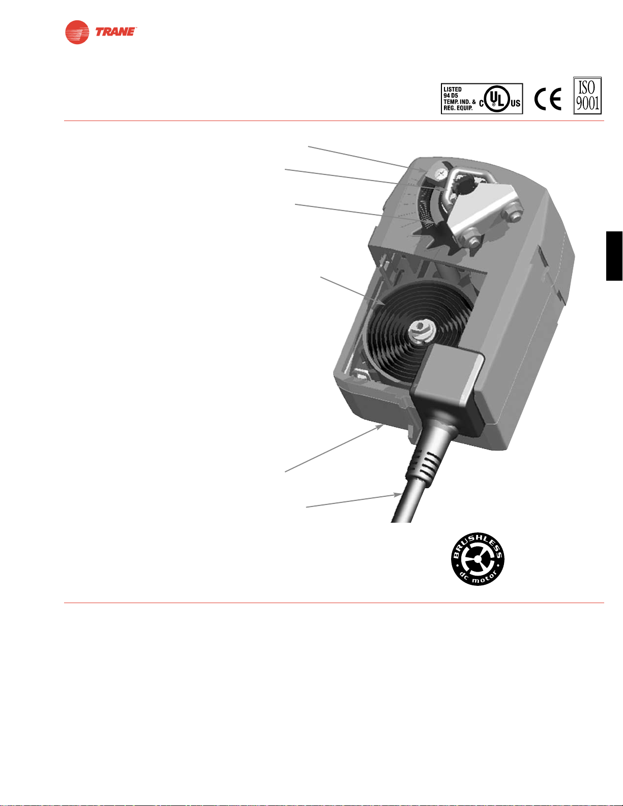
59
I20683 - Subject to change.
TTF
TTF Series Spring Return Direct Coupled Actuator
● Easy-to-adjust mechanical stop to limit damper rotation.
● Cut labor costs with simple direct coupling. actuator
centers on 1/2” shaft.
● Clockwise or counterclockwise fail-safe mounting
for fail-safe.
● Compact size with the shortest shaft-center to edge
distance in the industry - 0.77”.
● True mechanical spring return – the most reliable fail-safe.
● Check damper position easily with clear position indicator.
● Don’t worry about actuator burn-out.
It is overload-proof throughout rotation.
● Need to change control direction?
Do it easily with a simple switch (modulating actuators).
● Built-in auxiliary switch is easy to use, offers feedback
or signal for additional device.
● Microprocessor-controlled brushless DC motor increases
actuator life span and reliability, provides constant running
time (modulating actuators).
● Rugged housing withstands rough handling in the
mechanical room.
● 3 ft. standard cable and conduit connector (not shown)
eases installation.
A CLOSER LOOK…
The T rane Difference
● Low Installation and Life-Cycle Cost.
Easy installation. Accuracy and repeatability.
Low power consumption. No maintenance.
●
Long Service Life.
Components tested before assembly. Every product tested before shipment.
30 years direct coupled actuator design.
©
Page 60
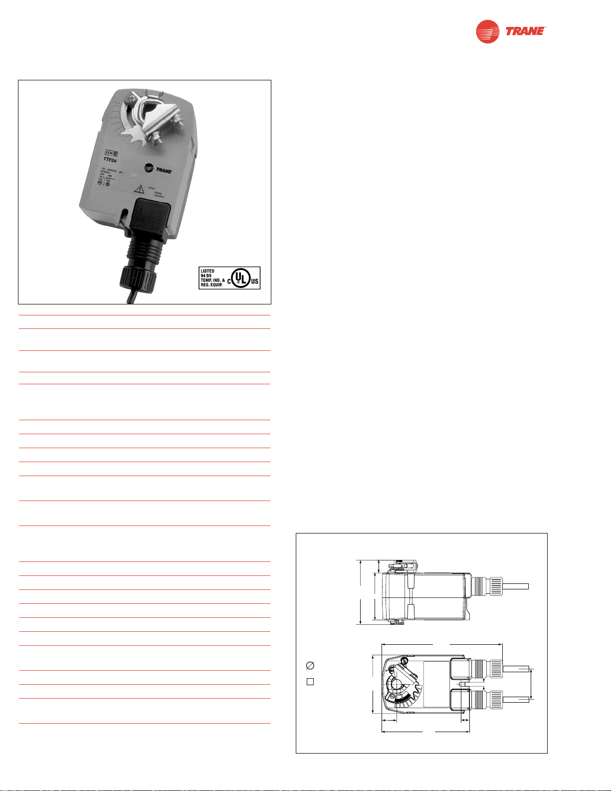
I20683 - Subject to change.
Torque min. 18 in-lb, for control of air dampers
Application
For on-off, fail-safe control of dampers in HVAC systems.
Actuator sizing should be done in accordance with the damper
manufacturer’s specifications. Control is on-off from an
auxiliary contact, or a manual switch.
The actuator is mounted directly to a damper shaft from 1/4”
up to 1/2” in diameter by means of its universal clamp, 1/2”
shaft centered at delivery. A crank arm and several mounting
brackets are available for applications where the actuator
cannot be direct coupled to the damper shaft.
Operation
The TTF series actuators provide true spring return operation
for reliable fail-safe application and positive close off on air tight
dampers. The spring return system provides consistent torque
to the damper with, and without, power applied to the actuator.
The TTF series provides 95° of rotation and is provided with a
graduated position indicator showing 0° to 90°.
The actuator may be stalled anywhere in its normal rotation
without the need of mechanical end switches. Power
consumption is reduced in holding mode.
The TTF24-S versions are provided with one built-in
auxiliary switch. This SPDT switch is provided for safety
interfacing or signaling, for example, for fan start-up. The
switching function is adjustable between 0° and 95°.
For all accessories, see pages 110 and 132.
Dimensions
[All numbers in brackets are in millimeters.]
TTF24 (-S)
On-off, Spring Return Fail-Safe, 24V
Technical Data TTF24 (-S)
Power supply 24VAC ± 20%, 50/60Hz
24VDC ± 10%
Power consumption running: 2.5 W
holding: 1.3 W
Transformer sizing 5 VA (class 2 power source)
Electrical connection 3 ft, 18 GA appliance cable
(-S models have 2 cables)
1/2” conduit connector
Overload protection electronic throughout 0° to 95° rotation
Angle of rotation max 95°, adjust. with mechanical stop
Torque min. 18 in-lb [2 Nm]
Direction of rotation reversible with cw/ccw mounting
Position indication visual indicator, 0° to 95°
(0° spring return position)
Auxiliary switch 1 x SPDT 3A (0.5A) @ 250 VAC,
(-S models) UL listed adjustable 0° to 95°
Running time motor: < 75 sec (0 to 18 in-lb)
spring: < 25 sec
@-4°F to +122°F [-20°C to +50°C]
< 60 sec
@-22°F [-30°C]
Humidity 5 to 95% RH non-condensing
Ambient temperature -22°F to +122°F [-30°C to +50°C]
Storage temperature -40°F to +176°F [-40°C to +80°C]
Housing NEMA type 2 / IP42
Housing material UL94- 5VA
Agency listings cULus listed acc. to UL 60730-1
Noise level max: running < 50 db (A)
spring return 62 dB (A)
Servicing maintenance free
Quality standard ISO 9001
Weight TTF24 1.4 lbs (0.6 kg)
TTF24-S 1.5 lbs (0.7 kg)
(nominal)
Safety Note
Screw a conduit fitting into the actuator’s bushing. Jacket the
actuator’s input and output wiring with suitable flexible conduit.
Properly terminate the conduit in a suitable junction box.
D096
60
Standard:
1/4" to 1/2"
1/4" to 5/16"
0.68" [16.7]
3.30"
[83.72]
2.40"
[61]
6.28"
[159.5]
3.0"
[76.2]
0.77" [19.5]
4.5"
[114]
0.43" [11]
0.2"
[5.2]
1.57"
[40]
Page 61
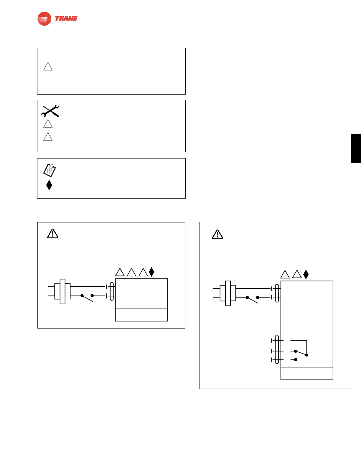
61
I20683 - Subject to change.
TTF
TTF24 (-S)
On-off, Spring Return FailS-Safe, 24 V
Wiring Diagrams
1 Common
2 + Hot
2
24 VAC Transformer
TTF24
35
WARNING
Live Electrical Components!
During installation, testing, servicing and troubleshooting of this product, it maybe
necessary to work with live electrical components. Have a qualified licensed electrician
or other individual who has been properly trained in handling live electrical components
perform these tasks. Failure to follow all electrical safety precautions when exposed
to live electrical components could result in death or serious injury.
1 Common
2 + Hot
2
24 VAC Transformer
TTF24-S
3
S1
S2
S3
NC
NO
0° to 95°
WARNING
Live Electrical Components!
During installation, testing, servicing and troubleshooting of this product, it maybe
necessary to work with live electrical components. Have a qualified licensed electrician
or other individual who has been properly trained in handling live electrical components
perform these tasks. Failure to follow all electrical safety precautions when exposed
to live electrical components could result in death or serious injury.
On-off wiring for TTF24
W467
W468
TTF24 (-S) Typical Specification
On-off spring return damper actuators shall be direct
coupled type which require no crankarm and linkage and
be capable of direct mounting to a shaft up to a 1/2”
diameter and center a 1/2” shaft. The actuators must be
designed so that they may be used for either clockwise or
counterclockwise fail-safe operation. Actuators shall be
protected from overload at all angles of rotation. If required,
one SPDT auxiliary switch shall be provided having the
capability of being adjustable. Actuators with auxiliary
switch must be constructed to meet the requirements for
double insulation so an electrical ground is not required
to meet agency listings. Actuators are cULus listed
certified and be manufactured under ISO 9001 International
Quality Control Standards. Actuators shall be as
manufactured by Belimo.
2
Equipment damage!
Actuators may be connected in parallel.
Power consumption must be observed and input
impedance must be observed.
3
5
Actuator may also be powered by 24 VDC.
Actuators with plenum rated cable do not have
numbers on wires; use color codes instead.
Actuators with appliance cables use numbers.
Meets cULus or UL and CSA requirements without
the need of an electrical ground connection.
CAUTION
INSTALLATION NOTES
APPLICATION NOTES
Page 62
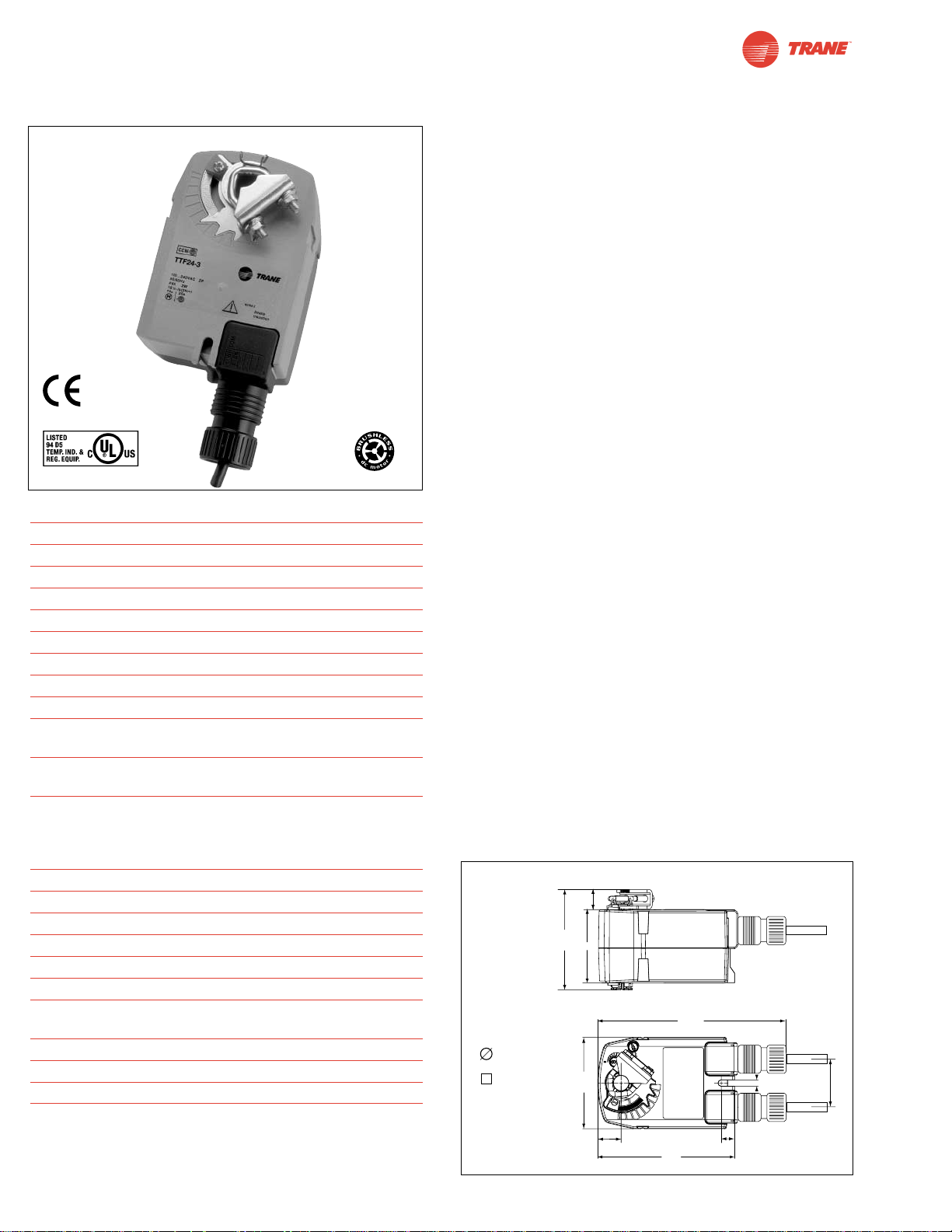
I20683 - Subject to change.
TTF24-3
On-off, Spring Return Fail-Safe, Reversible, Floating Point, 24V
Torque min. 18 in-lb, for control of air dampers
Application
For modulation or on-off control of dampers in HVAC systems.
Actuator sizing should be done in accordance with the damper
manufacturer’s specifications.
The actuator is mounted directly to a damper shaft from 1/4”
up to 1/2” in diameter by means of its universal clamp, 1/2”
shaft centered at delivery. A crank arm and several mounting
brackets are available for applications where the actuator
cannot be direct coupled to the damper shaft.
Control is floating point from a triac or relay, or on-off from
an auxiliary contact on a fan motor contactor, controller, or
manual switch.
Operation
The TTF series actuators provide true spring return operation
for reliable fail-safe application and positive close-off on air
tight dampers. The spring return system provides consistent
torque to the damper with, and without, power applied to the
actuator.
The TTF series provides 95° of rotation and is provided with a
graduated position indicator showing 0° to 95°.
The TTF24-3 uses a brushless DC motor which is controlled by
an Application Specific Integrated Circuit (ASIC) and a microprocessor. The microprocessor provides the intelligence to the
ASIC to provide a constant rotation rate. The ASIC monitors
and controls the brushless DC motor’s rotation and provides
a digital rotation sensing function to prevent damage to the
actuator in a stall condition. The actuator may be stalled
anywhere in its normal rotation without the need of mechanical
end switches. Power consumption is reduced in holding mode.
For all accessories, see pages 110 and 132.
Dimensions
[All numbers in brackets are in millimeters.]
Technical Data TTF24-3
Power supply 24 VAC ± 20% 50/60 Hz
Power consumption running: 2.5 W ; holding: 1 W
Transformer sizing 4 VA (class 2 power source)
Electrical connection TTF24-3 3 ft, 18 GA plenum rated cable
Overload protection electronic throughout 0° to 95° rotation
Input impedance 1000Ω (0.6w) control inputs
Angle of rotation max. 95°, adjust. with mechanical stop
Torque 18 in-lb [2 Nm]
Direction of rotation spring: reversible with cw/ccw mounting
motor: reversible with built-in switch
Position indication visual indicator, 0° to 95°
(0° is spring return position)
Running time motor: 95 sec constant,
independent of load
spring: < 25 sec
@-4°F to +122°F [-20°C to +50°C]
< 60 sec
@-22°F [-30°C]
Humidity 5 to 95% RH non-condensing
Ambient temperature -22°F to +122°F [-30°C to +50°C]
Storage temperature -40°F to +176°F [-40°C to +80°C]
Housing NEMA type 2 /IP42
Housing material UL94-5VA
Agency listings cULus listed acc. to UL 60730-1
Noise level max: running < 35 db (A)
spring return 62 dB (A)
Servicing maintenance free
Quality standard ISO 9001
Weight TTF24-3 1.4 lbs (0.6 kg.)
.
D096
62
©
Standard:
1/4" to 1/2"
1/4" to 5/16"
0.68" [16.7]
3.30"
[83.72]
2.40"
[61]
6.28"
[159.5]
3.0"
[76.2]
0.2"
[5.2]
1.57"
[40]
0.77" [19.5]
4.5"
[114]
0.43" [11]
Page 63
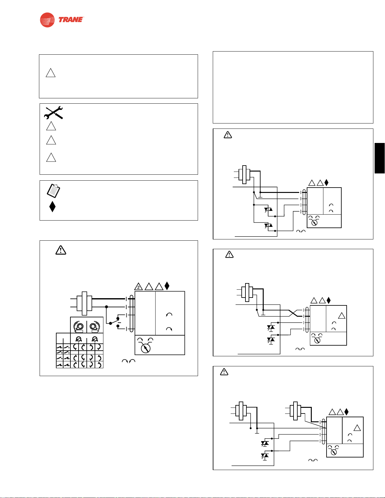
63
I20683 - Subject to change.
TTF
TTF24-3
On-off, Spring Return Fail-Safe, Reversible, Floating Point, 24V
TF24-3 Typical Specification
Floating point, on-off spring return damper actuators shall be direct
coupled type which require no crankarm and linkage and be capable
of direct mounting to a shaft up to a 1/2” diameter and center a 1/2”
shaft. The actuators must be designed so that they may be used for
either clockwise or counterclockwise fail-safe operation. Actuators
shall have an external direction of rotation switch to reverse control
logic. Actuators shall use a brushless DC motor and be protected
from overload at all angles of rotation. Run time shall be constant
and independent of torque. Actuators are cULus listed certified and
be manufactured under ISO 9001 International Quality Control
Standards. Actuators shall be as manufactured by Belimo.
Line
Volts
The indication of direction
is valid for switch position CW.
Blk (1) Common
Red (2)
~
Wht (W3) ~
Or (W4) ~
24 VAC Transformer
TTF24-3
b
CCW
CW
stop
a
(3) (4)
stop stop stop
Installation Side
Direction of Rotation Switch
x
x
x
x
x
x
x
x
xx
x
x
x
x
x
x
xx
x
x
x
x
x
x
x
x
x
x
x
x
x
x
x
x
x
xx
x
CW
CCW
Switch
Positions
CCW
CW
a
b
3 5
WARNING
Live Electrical Components!
During installation, testing, servicing and troubleshooting of this product, it maybe
necessary to work with live electrical components. Have a qualified licensed electrician
or other individual who has been properly trained in handling live electrical components
perform these tasks. Failure to follow all electrical safety precautions when exposed
to live electrical components could result in death or serious injury.
Wiring Diagrams
Triac source
Triac sink
Floating point control of TTF24-3
Triac sink with separate transformers
W470
W471
W472
W469
3
5
6
Actuator may also be powered by 24 VDC.
Actuators with plenum rated cable do not have
numbers on wires; use color codes instead. Actuators with
appliance cables use numbers.
For triac sink the common connection from the actuator must
be connected to the Hot connection of the controller. The
actuator must be connected to the control board common.
Meets cULus or UL and CSA requirements without the need
of an electrical ground connection.
CAUTION
2
Equipment damage!
Actuators may be connected in parallel.
Power consumption must be observed and input
impedance must be observed.
INSTALLATION NOTES
APPLICATION NOTES
WARNING
Live Electrical Components!
During installation, testing, servicing and troubleshooting of this product, it maybe necessary to work with live
electrical components. Have a qualified licensed electrician or other individual who has been properly trained
in handling live electrical components perform these tasks. Failure to follow all electrical safety precautions
when exposed to live electrical components could result in death or serious injury.
24 VAC Transformer
Line
Volts
2
5
Blk (1) Common
Red
(2) ~ Hot
Wht
(W3) ~
Or (W4) ~
TTF24-3
Controller
ComHot
The indication of direction
is valid for switch position CW.
WARNING
Live Electrical Components!
During installation, testing, servicing and troubleshooting of this product, it maybe necessary to work with live
electrical components. Have a qualified licensed electrician or other individual who has been properly trained
in handling live electrical components perform these tasks. Failure to follow all electrical safety precautions
when exposed to live electrical components could result in death or serious injury.
24 VAC Transformer
Line
Volts
7
ComHot
2
Blk (1) Common
Red
(2) ~ Hot
Wht
(W3) ~
6
Or (W4) ~
TTF24-3
Controller
The indication of direction
is valid for switch position CW.
WARNING
Live Electrical Components!
During installation, testing, servicing and troubleshooting of this product, it maybe necessary to work with live electrical components.
Have a qualified licensed electrician or other individual who has been properly trained in handling live electrical components
perform these tasks. Failure to follow all electrical safety precautions when exposed to live electrical components could result
in death or serious injury.
24 VAC Transformer
Line
Volts
ComHot
24 VAC Transformer
Line
Volts
2
5
Blk (1) Common
Red
(2) ~ Hot
Wht
(W3) ~
Or (W4) ~
TTF24-3
Controller
The indication of direction
is valid for switch position CW.
6
Page 64
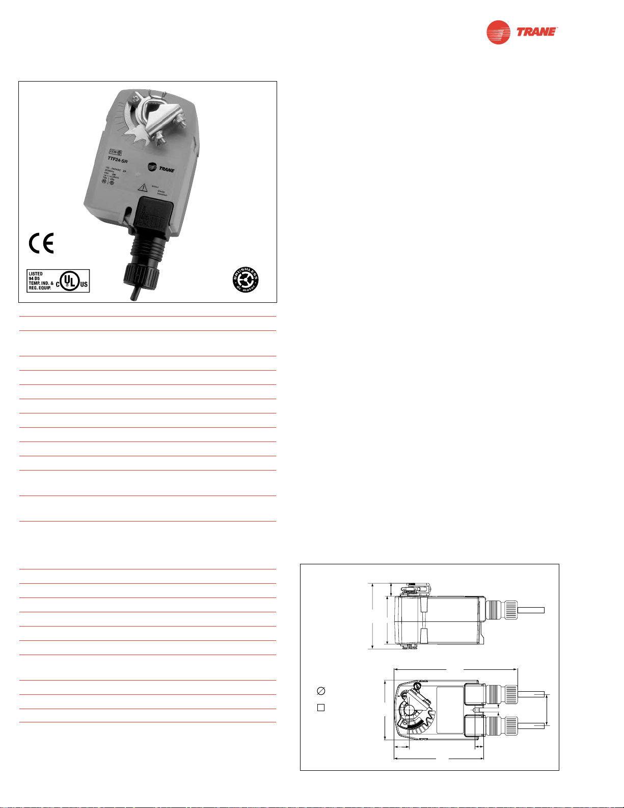
I20683 - Subject to change.
TTF24-SR
Proportional damper actuator, Spring Return Fail-Safe, 24 V for 2 to 10 VDC, or 4 to 20 mA Control Signal.
©
D096
Torque min. 18 in-lb, for control of air dampers
Application
For proportional modulation of dampers in HVAC systems.
Actuator sizing should be done in accordance with the damper
manufacturer’s specifications.
The actuator is mounted directly to a damper shaft from 1/4”
up to 1/2” in diameter by means of its universal clamp, 1/2”
shaft centered at delivery. A crank arm and several mounting
brackets are available for applications where the actuator
cannot be direct coupled to the damper shaft.
The actuator operates in response to a 2 to 10 VDC, or with the
addition of a 500Ω resistor, a 4 to 20 mA control input from an
electronic controller or positioner.
Operation
The TTF series actuators provide true spring return operation
for reliable fail-safe application and positive close-off on air tight
dampers. The spring return system provides consistent torque
to the damper with, and without, power applied to the actuator.
The TF series provides 95° of rotation and is provided with a
graduated position indicator showing 0° to 95°.
The TTF24-SR uses a brushless DC motor which is controlled
by an Application Specific Integrated Circuit (ASIC) and a
microprocessor. The microprocessor provides the intelligence
to the ASIC to provide a constant rotation rate and to know the
actuator’s exact fail-safe position. The ASIC monitors and
controls the brushless DC motor’s rotation and provides a
digital rotation sensing function to prevent damage to the
actuator in a stall condition. The actuator may be stalled
anywhere in its normal rotation without the need of mechanical
end switches. Power consumption is reduced in holding mode.
For all accessories, see pages 110 and 132.
Dimensions
[All numbers in brackets are in millimeters.]
Technical Data TTF24-SR
Power supply 24 VAC ± 20% 50/60 Hz
24 VDC ± 10%
Power consumption running: 2.5 W; holding: 1 W
Transformer sizing 4 VA (class 2 power source)
Electrical connection TF24-SR 3 ft, 18 GA plenum rated cable
Overload protection electronic throughout 0° to 95° rotation
Operating range Y 2 to 10 VDC, 4 to 20mA
Input impedance 100kΩ (0.1 mA), 500Ω
Angle of rotation max. 95°, adjust. with mechanical stop
Torque 18 in-lb [2 Nm]
Direction of rotation spring: reversible with cw/ccw mounting
motor: reversible with built-in switch
Position indication visual indicator, 0° to 95°
(0° is spring return position)
Running time motor: 95 sec constant,
independent of load
spring: < 25 sec
@-4°F to +122°F [-20°C to +50°C]
< 60 sec
@-22°F [-30°C]
Humidity 5 to 95% RH non-condensing
Ambient temperature -22°F to +122°F [-30°C to +50°C]
Storage temperature -40°F to +176°F [-40°C to +80°C]
Housing NEMA type 2 / IP42
Housing material UL94-5VA
Agency listings cULus listed acc. to UL 60730-1
Noise level max: running < 35 db (A)
spring return 62 dB (A)
Servicing maintenance free
Quality standard ISO 9001
Weight TTF24-SR 1.4 lbs (0.6 kg.)
64
Standard:
1/4" to 1/2"
1/4" to 5/16"
0.68" [16.7]
3.30"
[83.72]
2.40"
[61]
6.28"
[159.5]
3.0"
[76.2]
0.2"
[5.2]
1.57"
[40]
0.77" [19.5]
4.5"
[114]
0.43" [11]
Page 65
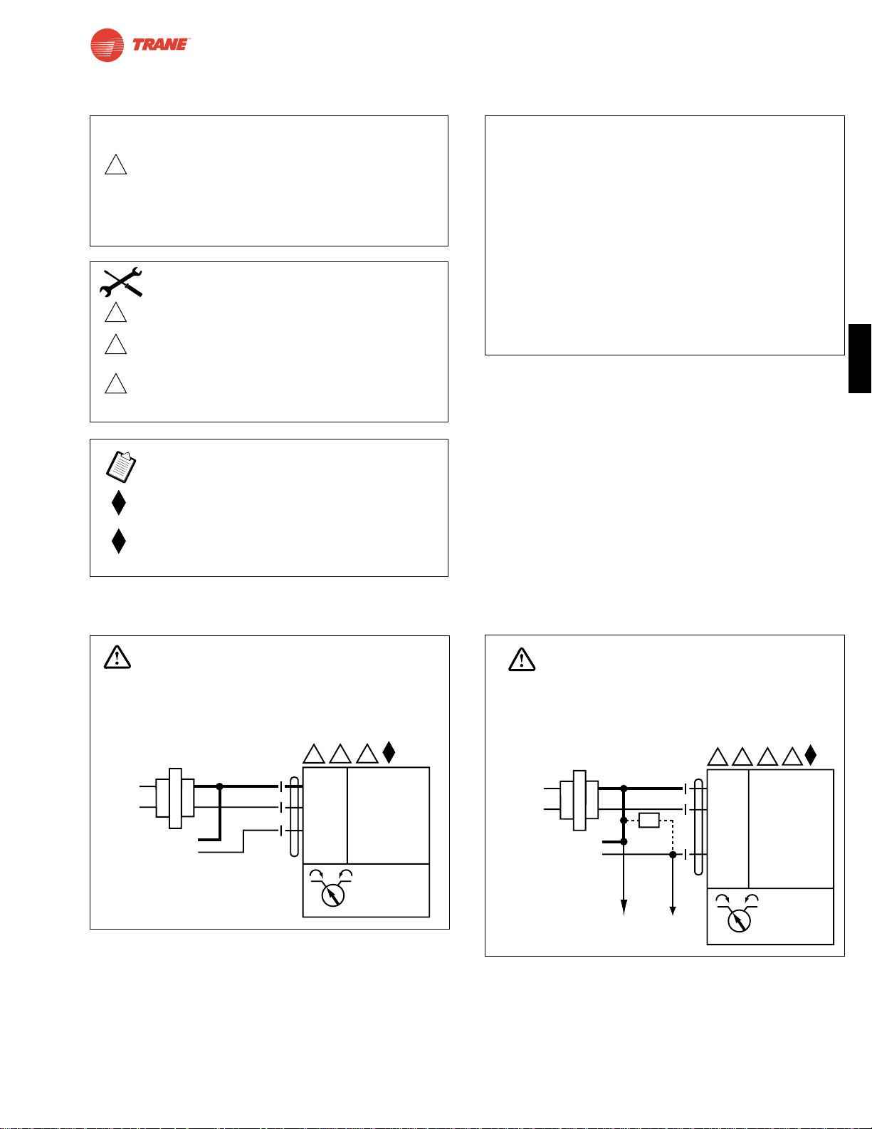
65
I20683 - Subject to change.
TTF
2 to 10 VDC control of TTF24-SR
TTF24-SR
Proportional damper actuator, Spring Return Fail-Safe, 24 V for 2 to 10 VDC, or 4 to 20 mA Control Signal.
TTF24-SR Typical Specification
Spring return control damper actuators shall be direct coupled
type which require no crankarm and linkage and be capable of
direct mounting to a shaft up to a 1/2” diameter and center a 1/2”
shaft. The actuator must provide proportional damper control
in response to a 2 to 10 VDC or, with the addition of a 500Ω
resistor, a 4 to 20 mA control input from an electronic controller
or positioner. The actuators must be designed so that they may
be used for either clockwise or counterclockwise fail-safe
operation. Actuators use a brushless DC motor controlled by a
microprocessor and be protected from overload at all angles of
rotation. Run time are constant, and independent of torque.
Actuators are cULus listed certified and be manufactured under
ISO 9001 International Quality Control Standards. Actuators shall
be as manufactured by Belimo.
Wiring Diagrams
1
5
2
3
24 VAC Transformer
Blk (1) Common
Red (2) + Hot
Wht (3) Y Input, 2 to 10V
TTF24-SR
Line
Volts
2 to 10 VDC
Control Signal
(–)
(+)
WARNING
Live Electrical Components!
During installation, testing, servicing and troubleshooting of this product, it maybe
necessary to work with live electrical components. Have a qualified licensed electrician
or other individual who has been properly trained in handling live electrical components
perform these tasks. Failure to follow all electrical safety precautions when exposed
to live electrical components could result in death or serious injury.
To other
actuators
6
24 VAC Transformer
Blk (1) Common
Red (2) + Hot
Wht (3) Y
Input, 2 to 10V
4 to 20 mA
Control Signal
(–)
(+)
Ω
500Ω
TTF24-SR
Line
Volts
1
5
2
3
WARNING
Live Electrical Components!
During installation, testing, servicing and troubleshooting of this product, it maybe
necessary to work with live electrical components. Have a qualified licensed electrician
or other individual who has been properly trained in handling live electrical components
perform these tasks. Failure to follow all electrical safety precautions when exposed
to live electrical components could result in death or serious injury.
4 to 20 mA control of TTF24-SR
W473
W474
2
Equipment damage!
Up to 4 actuators may be connected in parallel.
With 4 actuators wired to one 500Ω resistor.
Power consumption must be observed and input
impedance must be observed.
Meets cULus or UL and CSA requirements without
the need of an electrical ground connection.
The ZG-R01 500Ω resistor converts the 4 to 20 mA
control signal to 2 to 10 VDC.
3
5
6
Actuator may also be powered by 24 VDC.
Actuators with plenum rated cable do not have
numbers on wires; use color codes instead.
Actuators with appliance cables use numbers.
Only connect common to neg. (—) leg of control
circuits.
CAUTION
INSTALLATION NOTES
APPLICATION NOTES
Page 66
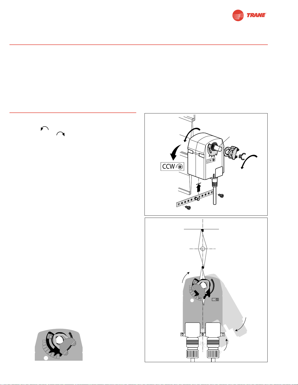
66
I20683 - Subject to change.
1. See Figure B. Manually move the damper to the fail-safe
position (a) (usually closed). If the shaft rotated counterclockwise ( ), this is a CCW installation. If the shaft
rotated clockwise ( ), this is a CW installation. In a
left hand installation, the actuator side marked “CW” faces
out, while in a CW installation, the side marked “CCW”
faces out. All other steps are identical.
2. The actuator is usually shipped with the universal clamp
mounted to the “CW” side of the actuator. To test for
adequate shaft length, slide the actuator over the shaft
with the side marked “CW” (or the “CCW” side if this is the
side with the clamp). If the shaft extends at least 1/8”
through the clamp, mount the actuator as follows. If not,
go to the Short Shaft Mounting section.
3. If the clamp is not on the correct side as determined in step
#1, re-mount the clamp as follows. If it is on the correct
side, proceed to step #5. Look at the universal clamp. If
you are mounting the actuator with the “CCW” side out,
position the clamp so that the pointer section of the tab is
pointing to 0° (see Figure C) and the spline pattern of the
clamp mates with spline of the actuator. Remount the stroke
limiter to this side then slip the clamp over the spline. (Use
the same procedure if the “CW” side is out.)
4. See Remounting the Stroke Limiter.
5. Lock the clamp to the actuator using the retaining clip.
6. Verify that the damper is still in its full fail-safe position (a).
7. Mount the spring return actuator to the shaft. Tighten the
universal clamp, finger tight only.
8. Mount the anti-rotation strap at the base of the actuator.
Do not tighten the screws.
9. Remove the screw from one end of the mounting bracket
and pivot it away from the actuator.
10. Loosen the universal clamp making sure not to move the
damper shaft, rotate the actuator approximately 5° in the
direction which would open the damper.
11. Tighten the universal clamp to the shaft.
12. Rotate the actuator to apply pressure to the damper seals
(b) and re-engage the anti-rotation strap (c).
13. Tighten all fasteners.
Installation Instructions
Standard Mounting / Airtight Damper Procedure
Mechanical Operation
The actuator is mounted directly to a damper shaft up to 1/2” in diameter by means of its universal clamp. A crank arm and several
mounting brackets are available for applications where the actuator cannot be direct coupled to the damper shaft.
The TTF series actuators provide true spring return operation for reliable fail-safe application and positive close-off on air tight
dampers. The spring return system provides consistent torque to the damper with, and without, power applied to the actuator.
The TTF series provides 95° of rotation and is provided with a graduated position indicator showing 0° to 95 °.
The TTF…-S versions are provided with one built-in auxiliary switch. This SPDT switch is provided for safety interfacing or signal-
ing, for example, for fan start-up. The switching function is adjustable between 0° and 95°.
Universal
Clamp
0
1
2
4
5
6
7
8
9
Figure BFigure C
0
1
2
4
5
6
7
8
9
L
C
b
c
a
CW
Standard
Mounting
Standard
Mounting
min 3-5/16”
[84]
Dimensions [All numbers in brackets are in millimeters.]
Page 67
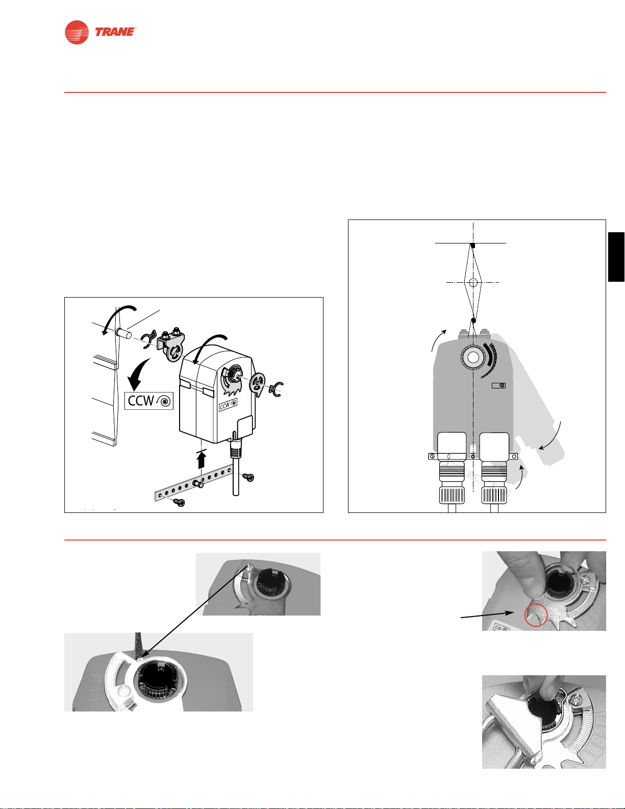
67
I20683 - Subject to change.
TTF
If the shaft extends at least 3/4” from the duct, follow these
steps:
1. See Figure D. Move damper blades to the fail-safe position (a).
2. Determine the best orientation for the universal clamp on the
back of the actuator. The best location would be where you
have the easiest access to the V bolt nuts on the clamp.
3. Engage the clamp to the actuator as close as possible to
the determined location.
4. Lock the clamp to the actuator using the retainer clip.
5. Mount the spring return actuator to the shaft. Tighten the
universal clamp, finger tight only.
6. Mount the anti-rotation strap at the base of the actuator. Do
not tighten the screws.
7. Remove the screw from one end of the mounting bracket
and pivot it away from the actuator.
8. Loosen the universal clamp and, making sure not to move
the damper shaft, rotate the actuator approximately 5° in
the direction which would open the damper.
9. Verify that the damper is still in its full fail-safe position.
10. Tighten the universal clamp to the shaft.
11. Rotate the actuator to apply pressure to the damper seals
(b) and re-engage the anti-rotation strap (c).
12. Tighten all fasteners.
13. Use IND-TF accessory if position indication is needed.
Installation Instructions
Short Shaft Mounting with IND-TF Position Indicator / Airtight Damper Procedure
ZDB-TF
min 3/4”
[20]
Figure D
0
1
2
4
5
6
7
8
9
CW
L
C
b
c
a
.2
.4
.6
.8
1
CW
0
Short Shaft
Mounting
Short Shaft
Mounting
Remounting the Stroke Limiter
1. Remove the stroke limiter
by inserting a small
screwdriver, like the one
shown, and gently prying
upward. This procedure
takes very little force.
See Figure 1.
2. While holding the back eye-let, unscrew the end-stop so
that eye-let separates from the end-stop.
3. Flip the limiter over, so
the teeth point the other
direction. Replace the
eye-let and end-stop.
4. Flip the actuator over to
the opposite side (this
reverses the spring
return direction of the actuator). Replace the stroke limiter
assembly by inserting the first two teeth as shown in the
orange circle. Then press the stroke limiter into place by
pushing downward on
the adjustable stop.
5. Replace clamp and
retaining clip.
Figure 1.
Dimensions [All numbers in brackets are in millimeters.]
Page 68
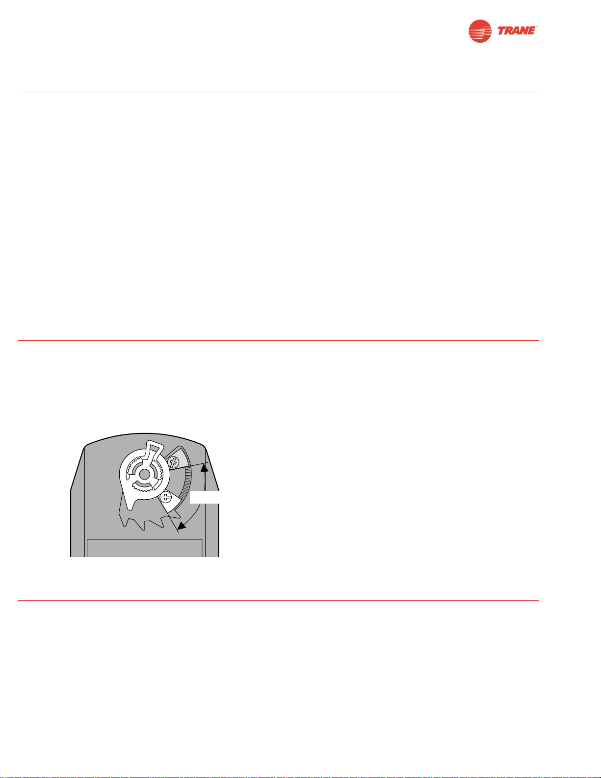
68
I20683 - Subject to change.
The TTF actuators are provided with an adjustable stop to
limit the rotation of the actuator. This function works in
conjunction with the universal clamp or the optional position
indicator. The adjustable stop is needed when rotation of less
than 95° is required. The TTF actuator can be indefinitely
stalled, in any position, without harming the actuator.
Using the Universal Clamp:
1. Loosen the end stop fastening screw using a #2 Phillips
screwdriver.
2. Move the stop block so the bottom edge of the block lines
up with the number corresponding to the desired degrees
of rotation (example: 45 degrees of rotation = .5).
3. Lock the block in place with the fastening screw.
4. Check the actuator for proper rotation.
Using the IND-TF Position Indicator with Adjustable Stop:
Note: preferred method if short shaft mounting is used.
1. With the actuator in its fail-safe position, place the IND-TF
Position Indicator so that it points to the 0 degree position.
2. Loosen the end stop fastening screw using a #2 Phillips
screwdriver.
3. Move the stop block so the bottom edge of the block lines
up with the number corresponding to the desired degrees
of rotation (example: 45 degrees of rotation = .5).
4. Lock the block in place with the fastening screw.
5. Check the actuator for proper rotation.
Mechanical Angle of Rotation Limiting
Installation Instructions
Quick-Mount Visual Instructions for Mechanical Installation
TTF24-3 and TTF24-SR actuators have a direction of rotation
switch on the cover labeled “CW-CCW”. Switch position indicates
start point. For the TTF24-SR, with the switch in position “CW”, the
actuator rotates clockwise with a decrease in voltage or current.
With the switch in position “CCW”, the actuator rotates counterclockwise with a decrease in voltage or current.
The TTF24-3 and TTF24-SR actuators rotate clockwise when the
switch is in the “CW” position and power is applied to wire #3.
When power is applied to wire #4 the actuator rotates counter
clockwise.
Rotating the direction of rotation switch to “CCW” reverses the
control logic.
During checkout, the switch position can be temporarily
reversed and the actuator will reverse its direction. This allows
the technician a fast and easy way to check the actuator operation without having to switch wires or change settings on the
controller. When the check-out is complete, make sure the
switch is placed back to its original position.
Direction of Rotation Switch
Initialization of the TTF24-SR
When power is applied, the internal microprocessor recognizes
that the actuator is at its full fail-safe position and uses this
position as the base for all of its position calculations. This
procedure takes approximately 15 seconds. During this time
you will see no response at the actuator. The microprocessor
will retain the initialized zero during short power failures of up
to 25 seconds. When power is applied during this period, the
actuator will return to normal operation and proceed to the
position corresponding to the input signal provided. For power
failures over 25 seconds, the actuator will be at its fail-safe
position and will go through the start up initialization again.
Motor Position Detection (TTF24-SR)
Brushless DC motors eliminate the need for potentiometers for
positioning. Inside the motor are three “Hall Effect” sensors.
These sensors detect the spinning rotor and send pulses to the
microprocessor which counts the pulses and calculates the
position to within 1/3 of a revolution of the motor.
Overload Protection
The TTF, on-off actuators are electronically protected against
overload. The TTF, on-off actuator have an internal current
limiter which maintains the current at a safe level which will not
damage the actuator while providing adequate holding torque.
The TTF24, modulating, actuators (TTF24-SR, TTF24-3) are
protected against overload by digital technology located in the
ASIC. The ASIC circuitry constantly monitors the rotation of the
brushless DC motor inside the actuator and stops the pulsing to
the motor when it senses a stall condition. The motor remains
energized and produces full rated torque during stall conditions.
The actuator will try to move in the direction of the stall every 2
minutes, for a period of 32 minutes. After this, the actuator will
try again every 2 hours.
Operational Information for TTF Actuators
37...100%
Page 69
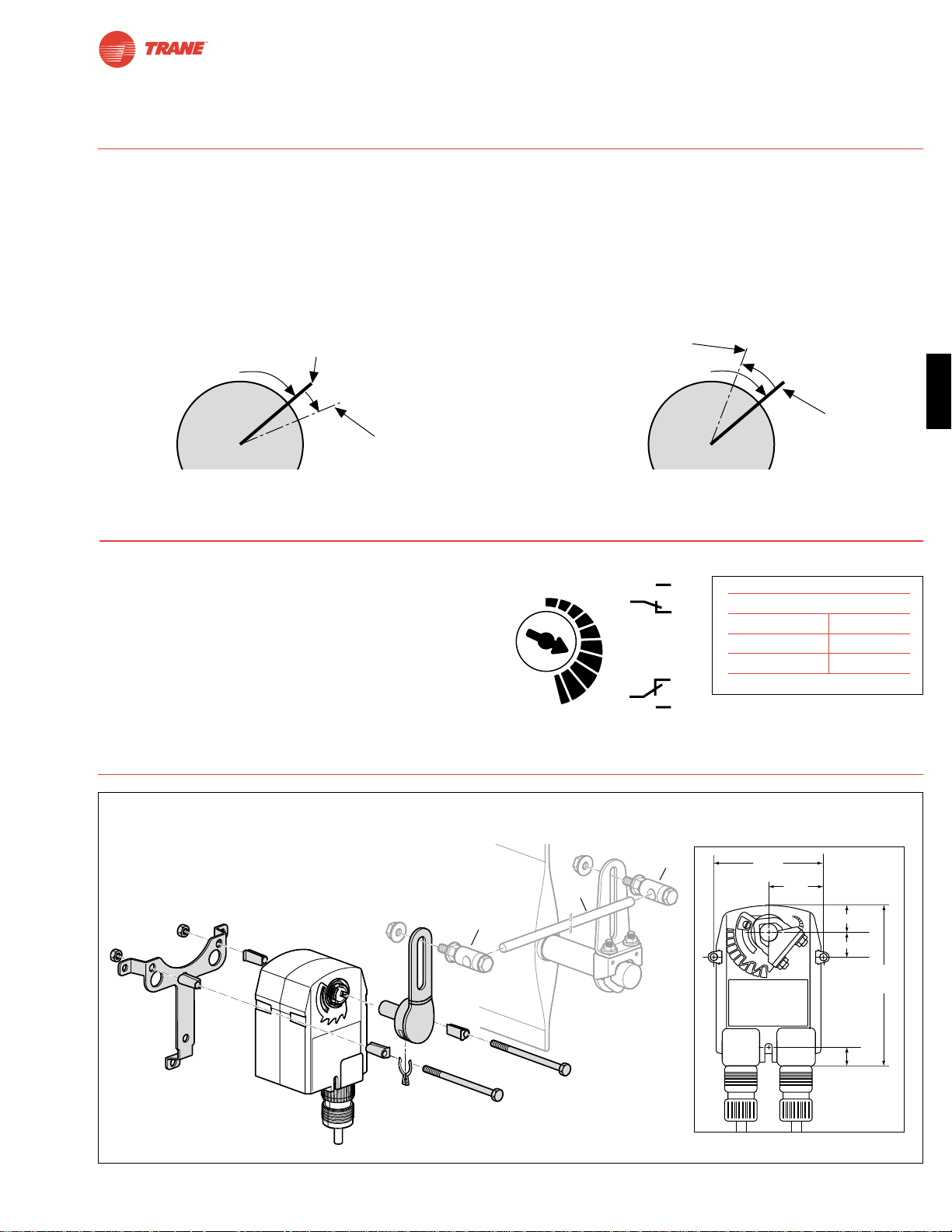
69
I20683 - Subject to change.
TTF
Satisfied
Control Position
Satisfied
Control Position
Minimum
Control Resolution
Minimum Reversed
Control Deadband
Prior to Normal Control
80 mV
200 m
V
TTF actuator responds to a 80 mV signal when
not changing direction from stop position.
TTF actuator responds to a 200 mV signal when
reversing direction from stop position.
Control Accuracy and Stability
Installation Instructions
The …-S model actuators are equipped with an adjustable
auxiliary switch used to indicate damper position or to interface additional controls or equipment. Switching positions
can be set over the full 0° to 95° rotation simply by setting a
switch on the actuator.
1. Set desired switch position (Example 60%).
2. As the actuator rotates, the switch indicator moves from
.6 (60%) toward 0 (0%).
Auxiliary Switches
Non-Direct Mounting Methods
Switch Rating
Voltage 250 VAC
Resistive load 3 A
Inductive load 0.5 A
3.15"
[81]
1.59"
[40.5]
0.77"
[19.5]
0.71"
[18]
0.43"
[11]
4.5"
[114]
KG6
KG6
SH8
Dimensions
[All numbers in brackets are in millimeters.]
TTF24-SR actuators have built-in brushless DC motors which provide better accuracy and longer service life.
The TTF24-SR actuators are designed with a unique non-symmetrical deadband. The actuator follows an increasing or
decreasing control signal with a 80 mV resolution. If the signal changes in the opposite direction, the actuator will not respond
until the control signal changes by 200 mV. This allows these actuators to track even the slightest deviation very accurately, yet
allowing the actuator to “wait” for a much larger change in control signal due to control signal instability.
ZG-TF2
Crankarm Adaptor Kit
0
.2
1
.8
.4
.6
S1
S1
S3
S2
S3
S2
Page 70

70
I20683 - Subject to change.
WARNING The wiring technician must be trained and experienced with electronic circuits. Disconnect power supply
before attempting any wiring connections or changes. Make
all connections in accordance with wiring diagrams and follow
all applicable local and national codes. Provide disconnect
and overload protection as required. Use copper, twisted pair,
conductors only. If using electrical conduit, the attachment to
the actuator must be made with flexible conduit.
Always read the controller manufacturer's installation
literature carefully before making any connections. Follow
all instructions in this literature. If you have any questions,
contact the controller manufacturer.
Transformer(s)
The TTF24 . . actuator requires a 24 VAC class 2 transformer
and draws a maximum of 5 VA per actuator. The actuator
enclosure cannot be opened in the field, there are no parts or
components to be replaced or repaired.
– EMC directive: 89/336/EEC
– Software class A: Mode of operation type 1
– Low voltage directive: 73/23/EEC
CAUTION: It is good practice to power electronic or digital
controllers from a separate power transformer than that used
for actuators or other end devices. The power supply design
in our actuators and other end devices use half wave rectification. Some controllers use full wave rectification. When these
two different types of power supplies are connected to the
same power transformer and the DC commons are connected
together, a short circuit is created across one of the diodes in
the full wave power supply, damaging the controller. Only use
a single power transformer to power the controller and
actuator if you know the controller power supply uses half
wave rectification.
Multiple Actuators, One Transformer
Multiple actuators may be powered from one transformer
provided the following rules are followed:
1. The TOTAL current draw of the actuators (VA rating) is
less than or equal to the rating of the transformer.
2. Polarity on the secondary of the transformer is strictly
followed. This means that all No. 1 wires from all
actuators are connected to the common leg on the
transformer and all No 2 wires from all actuators are
connected to the hotleg. Mixing wire No. 1 & 2 on one leg
of the transformer will result in erratic operation or failure
of the actuator and/or controls.
Multiple Actuators, Multiple Transformers
Multiple actuators positioned by the same control signal may
be powered from multiple transformers provided the following
rules are followed:
1. The transformers are properly sized.
2. All No. 1 wires from all actuators are tied together and tied
to the negative leg of the control signal. See wiring diagram.
Wire Length for TTF… Actuators
Keep power wire runs below the lengths listed in the table in
Figure A. If more than one actuator is powered from the same
wire run, divide the allowable wire length by the number of
actuators to determine the maximum run to any single actuator.
Example for TTF24-SR:
3 actuators, 16 Ga wire
550 ft ÷ 3 Actuators = 183 ft. maximum wire run
Maximum Wire Length:
Wire Size Max. Feet. Wire Size Max. Feet
12 Ga 1300 Ft. 18 Ga 575 Ft.
14 Ga 1175 Ft. 20 Ga 300 Ft.
16 Ga 900 Ft. 22 Ga 150 Ft.
Figure A
Wire Type and Wire Installation Tips
For most installations, 18 or 16 Ga. cable works well with the
TTF24… actuators. Use code-approved wire nuts, terminal
strips or solderless connectors where wires are joined. It is
good practice to run control wires unspliced from the actuator
to the controller. If splices are unavoidable, make sure the
splice can be reached for possible maintenance. Tape and/or
wire-tie the splice to reduce the possibility of the splice being
inadvertently pulled apart.
The TTF24… proportional actuators have a digital circuit that is
designed to ignore most unwanted input signals (pickup). In
some situations the pickup may be severe enough to cause
erratic running of the actuator. For example, a large inductive
load (high voltage AC wires, motors, etc.) running near the
power or control wiring may cause excessive pickup. To solve
this problem, make one or more of the following changes:
1. Run the wire in metallic conduit.
2. Re-route the wiring away from the source of pickup.
3. Use shielded wire (Belden 8760 or equal). Ground the
shield to an earth ground. Do not connect it to the
actuator common.
Brushless DC Motor Operation
The brushless DC motor spins by reversing the poles of
stationary electromagnets housed inside rotating permanent
magnets. The electromagnetic poles are switched by a microprocessor and a special ASIC (Application Specific Integrated
Circuit). Unlike the conventional DC motor, there are no
brushes to wear or commutators to foul.
Wire Size Max. Feet. Wire Size Max. Feet
12 Ga 1800 Ft. 18 Ga 450 Ft.
14 Ga 1100 Ft. 20 Ga 275 Ft.
16 Ga 700 Ft. 22 Ga 125 Ft.
Installation Instructions
General Wiring
TTF24 (-S)
TTF24-3
TTF24-SR
Wire Size Max. Feet. Wire Size Max. Feet
16 Ga 1125 Ft. 20 Ga 400 Ft.
18 Ga 725 Ft. 22 Ga 200 Ft.
Page 71
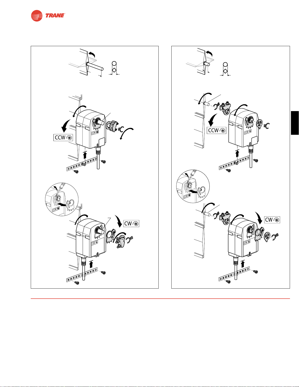
71
I20683 - Subject to change.
TTF
Preliminary Steps
1. Actuators should be mounted indoors in dry, relatively
clean environment free from corrosive fumes. If the actuator is to be mounted outdoors, a protective enclosure must
be used to shield the actuator. (See Mechanical
Accessories Section)
2. For new construction work, order dampers with extended
shafts. Instruct the installing contractor to allow space for
mounting and service of the actuator on the shaft.
3. For standard mounting, the damper shaft must extend at least
3 1/2" from the duct. If the shaft extends less than 3 1/2", the
actuator may be mounted in its short shaft configuration.
Installation Instructions
Quick-Mount Visual Instructions
1. Rotate the damper to its failsafe position. If the shaft rotates
counterclockwise, mount the “CCW” side of the actuator out. If it
rotates clockwise, mount the actuator with the “CW” side out.
2. If the universal clamp is not on the correct side of the actuator, move it to the correct side.
3. Slide the actuator onto the shaft and tighten the nuts on the
V-bolt with an 8 mm wrench to 6-8 ft-lb of torque.
4. Slide the anti-rotation strap under the actuator so that it
engages the slot at the base of the actuator. Secure the
strap to the duct work with #8 self-tapping screws.
NOTE: Read the “Standard Mounting” instructions, on page 92,
for more detailed information.
min 3-5/16”
[84]
min 3-5/16”
[84]
1/4” to1/2”
[6-12]
m
in
. 3-5/1
6
”
[80]
ZDB-TF
min 3/4”
[20]
min 3/4”
[20]
ZDB-TF
m
in
. 3
/4
”
[20
]
1/4” to 1/2”
[6-12]
Standard
Mounting
Short Shaft
Mounting
Dimensions
[All numbers in brackets are in millimeters.]
Quick-Mount Visual Instructions
Page 72

72
I20683 - Subject to change.
Startup and Checkout
Instructions For TTF24-SR
Procedure
Remove power to reset actuator.
Re-apply power.
Apply control signal to actuator.
Check power wiring. Correct any
problems. See Note 1.
Turn reversing switch to the correct
position. Make sure the switch is
turned all the way left or right.
Make sure the control signal positive
(+) is connected to Wire No 3 and
control signal negative (-) is connected to wire No. 1. Most control problems are caused by reversing these
two wires. Verify that the reversing
switch is all the way CCW or CW.
Check input signal with a digital volt
meter (DVM). Make sure the input is
within the range of the actuator. For
TTF24-SR this is 2 to 10 VDC or
4 to 20 mA. Note: The input signal
must be above the 2 VDC or 4 mA to
have the actuator move.
Loosen the nuts on the V-bolt and
move the damper by hand from fully
closed to fully open.
Check damper torque requirement.
Actuator works properly. Test
controller by following controller
manufacturer's instructions.
Expected Response
Actuator will move to its “Control
Signal” position.
Power supply rating should be
≥
the total power requirement of
the actuator(s). Minimum voltage of 19.2 VAC or 21.6 VDC.
Actuator will move to its “Control
Signal” position.
Drives to “Control Signal”
position.
Input voltage or current should be
±1% of what controller's adjustment or programming indicate.
Damper will go from fully closed
to fully open.
Torque requirement is ≤
actuator’s minimum torque.
Gives Expected
Response
Go To Step…
Actuator operates
properly.
Step 8
Power wiring correct-
ed, actuator begins
to drive.
Step 1
Actuator operates
properly.
Step 8
Actuator operates
properly.
Step 8
Controller output
(actuator input) is
correct. Input
Polarity Correct.
Step 6
Damper moves
properly.
Step 7
Defective Actuator.
Replace Actuator.
Does Not Give
Expected Response
Go To Step…
No response at all.
Step 2
Operation is
reversed.
Step 3
Does not drive
toward "Control
Signal Position".
Step 4
Power wiring
corrected, actuator
still does not drive.
Step 4
Does not drive
toward “Control
Signal Position”.
Step 4
Step 5
Reprogram, adjust
repair or replace
controller as needed.
Step 1
Find cause of damper
jam and repair. Move
damper back to the
fully closed position
and tighten the nuts.
Step 1
Recalculate actuator
requirement and
correct installation.
Step
1.
2.
3.
4.
5.
6.
7.
8.
Note 1 Check that the transformer(s) are sized properly.
• If a common transformer is used, make sure that polarity is observed on the secondary. This means connect all No. 1
wires to one leg of the transformer and all No. 2 wires to the other leg of the transformer.
• If multiple transformers are used with one control signal, make sure all No. 1 wires are tied together and tied to control
signal negative (-).
• Controllers and actuators must have separate 24 VAC/VDC power sources.
TTF24-SR Electrical Check-out Procedure
Page 73

73
I20683 - Subject to change.
TTF
Notes/Work Pad
Page 74

TGMB Series Direct Coupled Actuator
74
I20683 - Subject to change.
Minimum 360 in-lb Torque
● For damper areas up to 90 sq-ft*
All Actuators
have BDCM
TGMB24-3
TGMB24-SR
TGMB Series - At A Glance
Pages 76 78
Basic Product ●●
Torque 360 in-lb [40 Nm] ●●
Angle of Rotation 95 degrees ●●
Power Supply 24 VAC/DC ●●
Control Input On/Off, Floating Point ●
2 to 10 VDC (4 to 20mA) ●
Feedback None ●
2 to 10 VDC ●
Running Time 150 seconds ●●
Wiring Plenum Rated Cable ●●
Conduit Fitting ●●
Auxiliary Switch Add-on ●●
Installation and Operations…(page 99).
*Based on 4 in-lb/ft2damper torque loading. Parallel blade. No edge seals.
©
Page 75
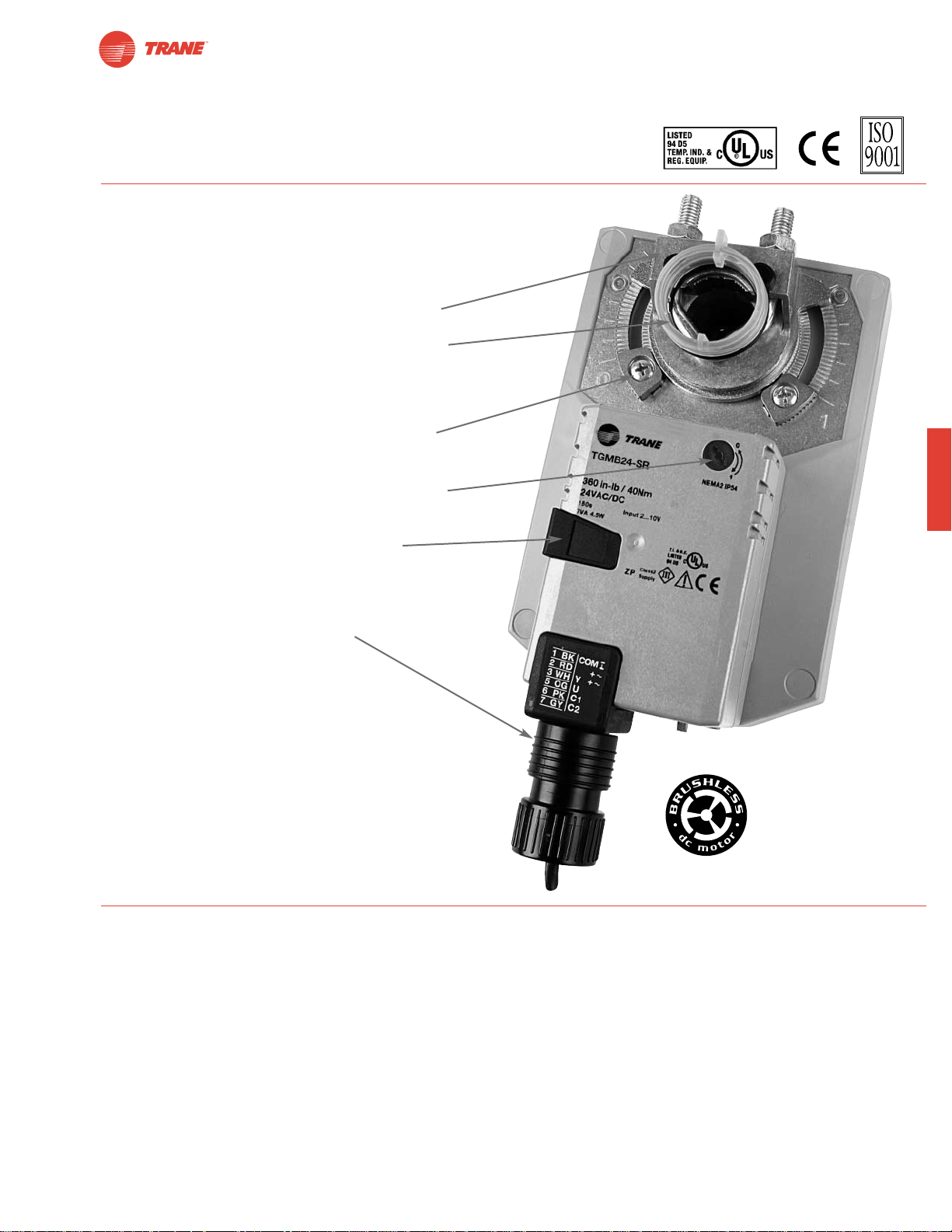
75
I20683 - Subject to change.
TGMB
● Brushless DC motor for added accuracy and
controllability.
● Cut labor costs with simple direct coupling.
● Self-centers on 1" jackshaft with standard clamp
or 3/4” with accessory clamp.
● Check damper position with clear position indicator.
● Don’t worry about actuator burn-out;
It is overload proof throughout rotation.
● Enjoy added flexibility with easy mechanical stops
to adjust angle of rotation.
● Need to change control direction? Do it easily with
a simple switch.
● Easily accessible manual override button
helps you pre-tension damper blades.
● Auxiliary switch and feedback potentiometer add-ons
mount directly on clamp, includes conduit connector.
● Standard 3ft plenum rated cable and conduit
connector provided.
TGMB Series Direct Coupled Actuator
The T rane Difference
● Low Installation and Life-Cycle Cost.
Easy installation. Accuracy and repeatability.
Low power consumption. No maintenance.
●
Long Service Life.
Components tested before assembly. Every product tested before shipment.
30+ years direct coupled actuator design.
©
A CLOSER LOOK…
Page 76
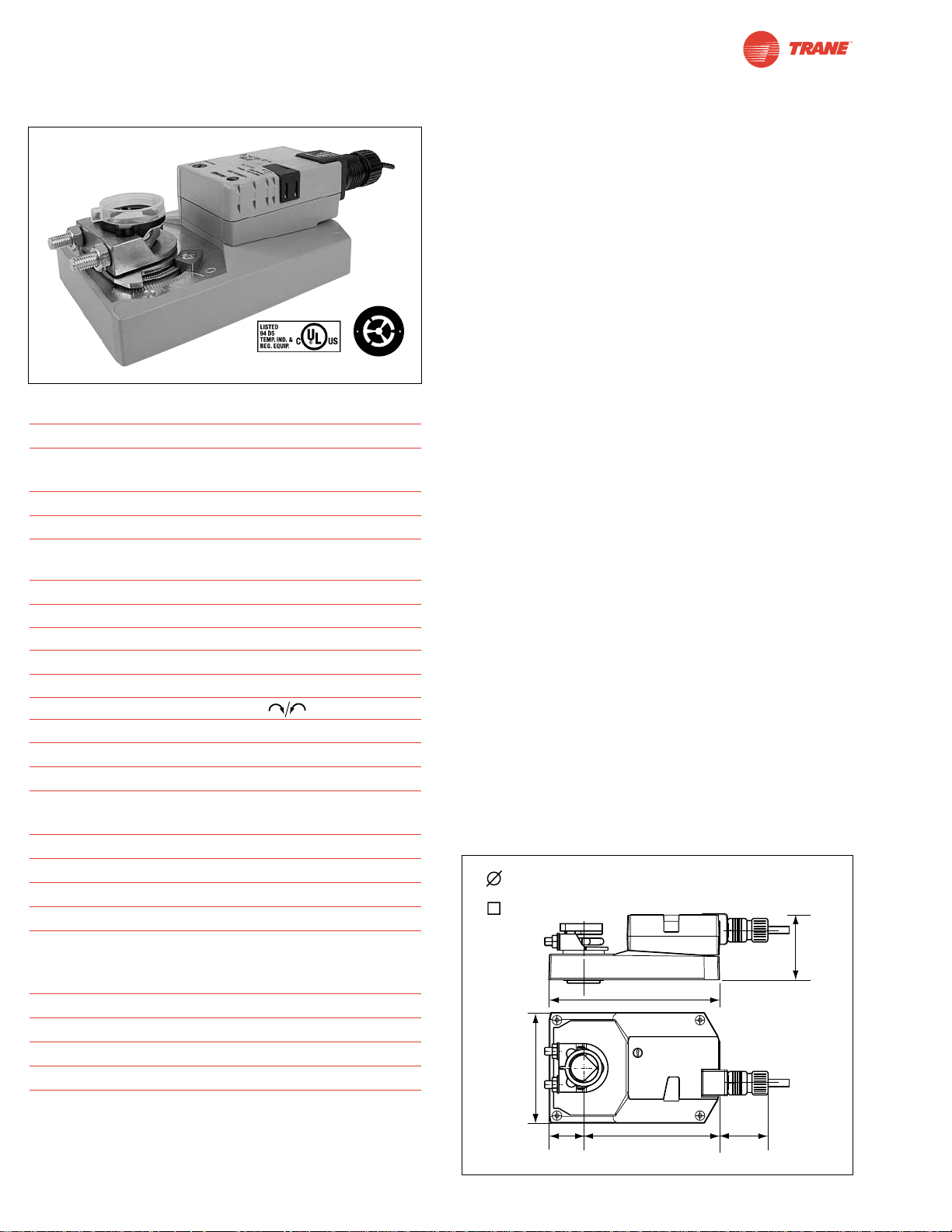
76
I20683 - Subject to change.
TGMB24-3
On/off-Floating Point Control, Non-Spring Return, Direct Coupled, 24 V
Technical Data TGMB24-3
Power Supply 24 VAC ± 20% 50/60 Hz
24 VDC ± 10%
Power Consumption 4 W (2 W)
Transformer Sizing 6 VA (Class 2 power source)
Electrical Connection 3 ft, 18 GA plenum rated cable
1/2” conduit connector
Overload Protection electronic throughout 0° to 95° rotation
Control on/off, floating point
Input Impedance 600Ω
Angle of Rotation max. 95°, adjust. with mechanical stop
Torque 360 in-lb [40 Nm]
Direction of Rotation reversible with switch
Position Indication reflective visual indicator (snap-on)
Manual Override external push button
Running Time 150 seconds, constant independent of load
Humidity 5 to 95% RH non condensing
(EN 60730-1)
Ambient Temperature -22°F to +122°F [-30°C to +50°C]
Storage Temperature -40°F to +176°F [-40°C to +80°C]
Housing NEMA 2/IP54
Housing Material UL94-5VA
Agency Listings cULus acc. to UL 60730-1/-2-14 and
CAN/CSA C22.2 No.24, CE according
to 73 / 23 / EEC
Noise Level <45dB(A)
Servicing maintenance free
Quality Standard ISO 9001
Weight 3.4 lbs [1.55 Kg]
Torque min. 360 in-lb for control of damper
surfaces up to 90 sq ft.
Application
For on/off and floating point control of dampers in HVAC
systems. Actuator sizing should be done in accordance with
the damper manufacturer’s specifications.
The actuator is mounted directly to a damper shaft up to 1.05”
in diameter by means of its universal clamp. A crankarm and
several mounting brackets are available for applications
where the actuator cannot be direct coupled to the damper
shaft.
Operation
The actuator is not provided with and does not require any
limit switches, but is electronically protected against overload.
The anti-rotation strap supplied with the actuator will prevent
lateral movement.
The TGMB series provides 95° of rotation and a visual
indicator indicates position of the actuator. When reaching
the damper or actuator end position, the actuator automatically stops. The gears can be manually disengaged with a
button on the actuator cover.
The TGMB24-3… actuators use a brushless DC motor, which
is controlled by an Application Specific Integrated Circuit
(ASIC). The ASIC monitors and controls the actuator’s
rotation and provides a digital rotation sensing (DRS) function
to prevent damage to the actuator in a stall condition. Power
consumption is reduced in holding mode.
Add on auxiliary switches or feedback potentiometers are
easily fastened directly onto the actuator body for signaling
and switching functions.
For all accessories, see pages 110 and 132.
Dimensions
(All numbers in brackets are in millimeters.)
D123
O
M
L
©
O
A
H
B
r
r
o
u
t
s
o
h
M
l
e
s
C
s
D
5/8” to 1” [16 to 25]
1" Centered
7/16” to 11/16” [11 to 17]
7.02” [178.4]
4.55” [115.6]
2.9” [72.9]
1.42”
[36]
5.6” [142.4]
2” [50.8]
Page 77
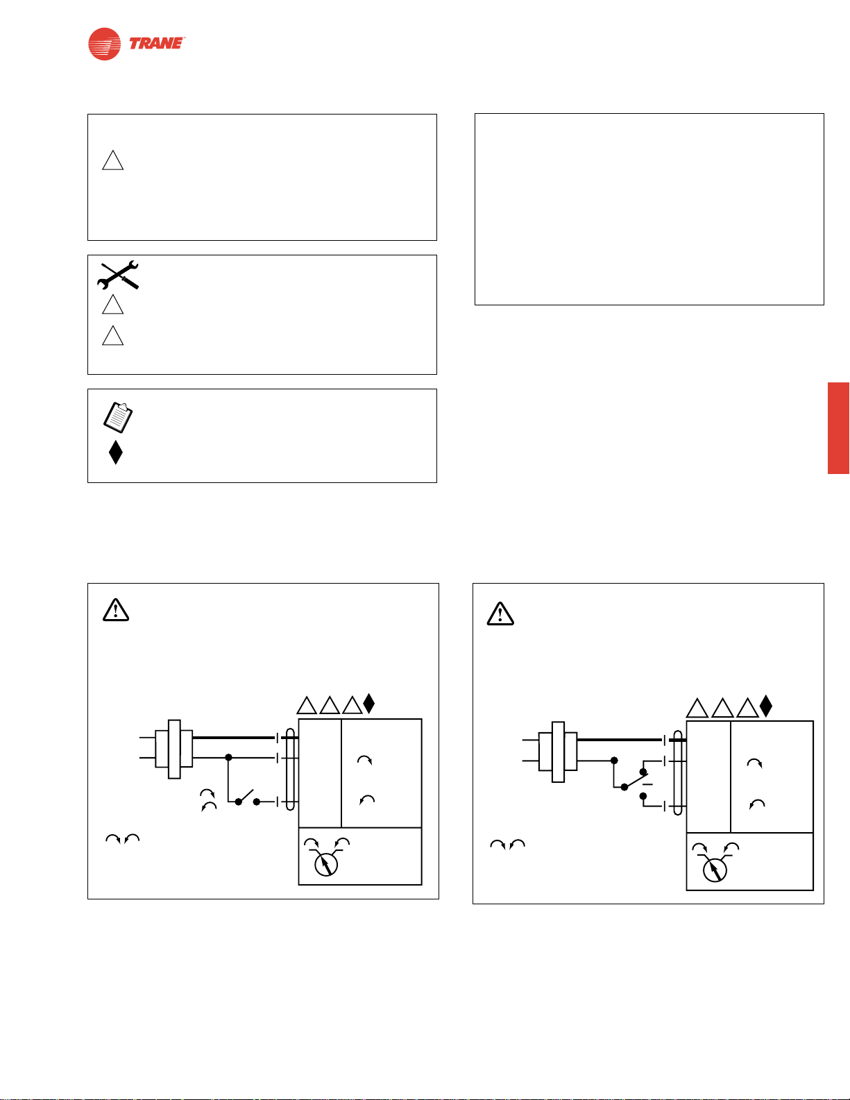
Wiring Diagrams
77
I20683 - Subject to change.
TGMB
TGMB24-3 - Typical Specification:
Floating point, on/off control damper actuators shall be
electronic direct-coupled type, which require no crankarm
and linkage and be capable of direct mounting to a shaft up
to 1.05” diameter. Actuators shall have brushless DC
motor technology and be protected from overload at all
angles of rotation. Actuators shall have reversing switch
and manual override on the cover. Run time shall be
constant and independent of torque. Actuators are cULus
listed, and be manufactured under ISO 9001 International
Quality Control Standards. Actuators shall be as
manufactured by Belimo.
TGMB24-3
On/Off-Floating Point Control, Non-Spring Return, Direct Coupled, 24 V
W478
W479
On/Off
Floating point or On/Off control
2
Equipment damage!
Up to 4 actuators may be connected in parallel.
With 4 actuators wired to one 500Ω resistor.
Power consumption must be observed and input
impedance must be observed.
Meets cULus or UL and CSA requirements without
the need of an electrical ground connection.
3
5
Actuator may also be powered by 24 VDC.
Actuators with plenum rated cable do not have
numbers on wires; use color codes instead.
Actuators with appliance cables use numbers.
CAUTION
INSTALLATION NOTES
APPLICATION NOTES
WARNING
Live Electrical Components!
During installation, testing, servicing and troubleshooting of this product, it maybe
necessary to work with live electrical components. Have a qualified licensed electrician
or other individual who has been properly trained in handling live electrical components
perform these tasks. Failure to follow all electrical safety precautions when exposed
to live electrical components could result in death or serious injury.
24 VAC Transformer
Line
Volts
a open
a closed
The indication of direction
is valid for switch position 1.
WARNING
Live Electrical Components!
During installation, testing, servicing and troubleshooting of this product, it maybe
necessary to work with live electrical components. Have a qualified licensed electrician
or other individual who has been properly trained in handling live electrical components
perform these tasks. Failure to follow all electrical safety precautions when exposed
to live electrical components could result in death or serious injury.
5
3
2
Blk (1) Common
Red (2) +
a
Wht (3) +
1 0
–
TGMB24-3
24 VAC Transformer
Line
Volts
The indication of direction
is valid for switch position 1.
5
3
2
Blk (1) Common
Red (2) +
Wht (3) +
1 0
TGMB24-3
–
Page 78
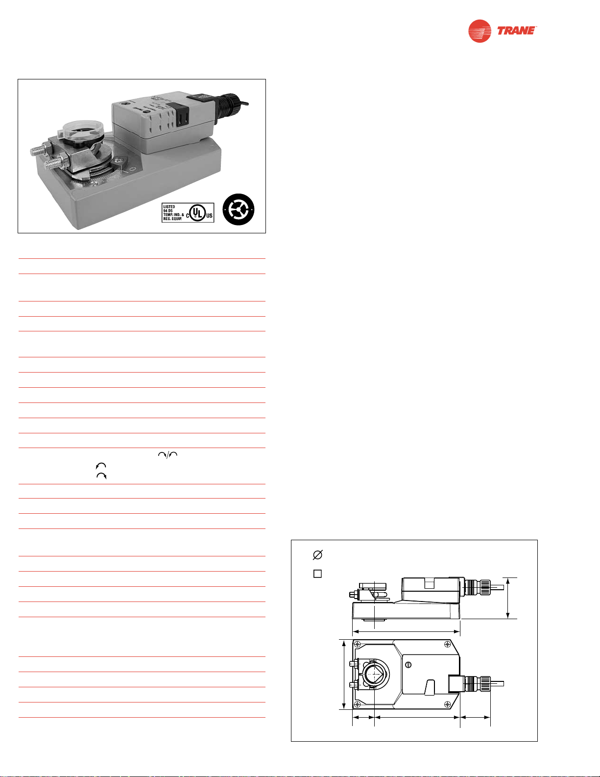
78
I20683 - Subject to change.
TGMB24-SR
Proportional Control, Non-Spring Return, Direct Coupled, 24V, for 2 to 10 VDC and 4 to 20 mA
Technical Data TGMB24-SR
Power Supply 24 VAC ± 20% 50/60 Hz
24 VDC ± 10%
Power Consumption 4.5 W (2W)
Transformer Sizing 6.5 VA (Class 2 power source)
Electrical Connection 3 ft, 18 GA plenum rated cable
1/2” conduit connector
Overload Protection electronic throughout 0° to 95° rotation
Operating Range Y 2 to 10 VDC, 4 to 20 mA
Input Impedance 100kΩ (0.1 mA), 500Ω
Feedback Output U 2 to 10 VDC (max 0.5 mA)
Angle of Rotation max. 95°, adjust. with mechanical stop
Torque 360 in-lb [40 Nm]
Direction of Rotation
reversible with switch. Actuator will move:
=CCW with decreasing control signal (10➞2V)
=CW with decreasing control signal (10➞2V)
Position Indication reflective visual indicator (snap-on)
Manual Override external push button
Running Time 150 seconds, constant independent of load
Humidity 5 to 95% RH non condensing
(EN 60730-1)
Ambient Temperature -22°F to +122°F [-30°C to +50°C]
Storage Temperature -40°F to +176°F [-40°C to +80°C]
Housing NEMA 2/IP54
Housing Material UL94-5VA
Agency Listings cULus acc. to UL 60730-1/-2-14 and
CAN/CSA C22.2 No.24, CE according
to 73 / 23 / EEC
Noise Level <45dB(A)
Servicing maintenance free
Quality Standard ISO 9001
Weight 3.4 lbs [1.55 Kg]
Torque min. 360 in-lb for control of damper
surfaces up to 90 sq ft.
Application
For proportional modulation of dampers in HVAC systems.
Actuator sizing should be done in accordance with the
damper manufacturer’s specifications.
The actuator is mounted directly to a damper shaft up to 1.05”
in diameter by means of its universal clamp. A crankarm and
several mounting brackets are available for applications
where the actuator cannot be direct coupled to the damper
shaft.
The actuator operates in response to a 2 to 10 VDC, or with
the addition of a 500Ω resistor, a 4 to 20 mA control input
from an electronic controller or positioner. A 2 to 10 VDC
feedback signal is provided for position indication or
master-slave applications.
Operation
The actuator is not provided with and does not require any
limit switches, but is electronically protected against overload.
The anti-rotation strap supplied with the actuator will prevent
lateral movement.
The TGMB series provides 95° of rotation and a visual indicator
indicates position of the actuator. When reaching the damper or
actuator end position, the actuator automatically stops. The gears
can be manually disengaged with a button on the actuator cover.
The TGMB24-SR… actuators use a sensorless brushless DC
motor, which is controlled by an Application Specific
Integrated Circuit (ASIC). The ASIC monitors and controls the
actuator’s rotation and provides a digital rotation sensing
(DRS) function to prevent damage to the actuator in a stall
condition. Power consumption is reduced in holding mode.
Add on auxiliary switches or feedback potentiometers are
easily fastened directly onto the actuator body for signaling
and switching functions
For all accessories, see pages 110 and 132.
Dimensions
(All numbers in brackets are in millimeters.)
D123
O
M
L
©
O
A
H
B
r
r
o
u
t
s
o
h
M
l
e
s
C
s
D
5/8” to 1” [16 to 25]
1" Centered
7/16” to 11/16” [11 to 17]
7.02” [178.4]
4.55” [115.6]
1.42”
[36]
5.6” [142.4]
2.9” [72.9]
2” [50.8]
Page 79
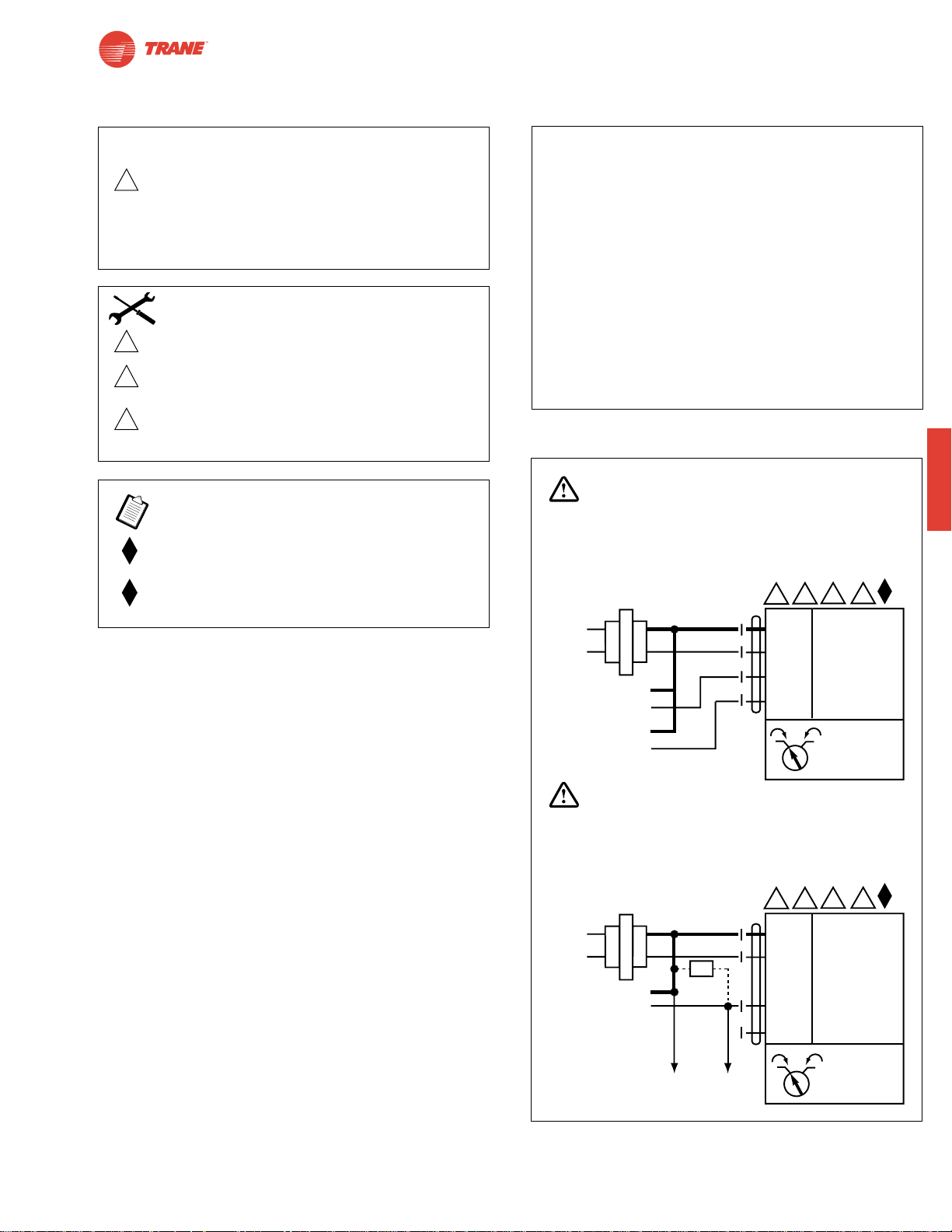
79
I20683 - Subject to change.
TGMB
TGMB24-SR
Proportional Control, Non-Spring Return, Direct Coupled, 24V, for 2 to 10 VDC and 4 to 20 mA
TGMB24-SR - Typical Specification:
Proportional control damper actuators shall be electronic
direct-coupled type, which require no crankarm and linkage
and be capable of direct mounting to a shaft up to 1.05”
diameter. Actuators must provide proportional damper
control in response to a 2 to 10 VDC or, with the addition
of a 500Ω resistor, a 4 to 20 mA control input from an
electronic controller or positioner. Actuators shall have
brushless DC motor technology and be protected from
overload at all angles of rotation. Actuators shall have
reversing switch and manual override on the cover. Run
time shall be constant and independent of torque. A 2 to
10 VDC feedback signal shall be provided for position
indication. Actuators are cULus listed, and be
manufactured under ISO 9001 International Quality Control
Standards. Actuators shall be as manufactured by Belimo.
Wiring Diagrams
W480
2 to 10 VDC and 4 to 20 mA control of TGMB24-SR
2
Equipment damage!
Up to 4 actuators may be connected in parallel.
With 4 actuators wired to one 500Ω resistor.
Power consumption must be observed and input
impedance must be observed.
Meets cULus or UL and CSA requirements without
the need of an electrical ground connection.
The ZG-R01 500Ω resistor converts the 4 to 20 mA
control signal to 2 to 10 VDC.
3
5
6
Actuator may also be powered by 24 VDC.
Actuators with plenum rated cable do not have
numbers on wires; use color codes instead.
Actuators with appliance cables use numbers.
Only connect common to neg. (—) leg of control
circuits.
CAUTION
INSTALLATION NOTES
APPLICATION NOTES
WARNING
Live Electrical Components!
During installation, testing, servicing and troubleshooting of this product, it maybe
necessary to work with live electrical components. Have a qualified licensed electrician
or other individual who has been properly trained in handling live electrical components
perform these tasks. Failure to follow all electrical safety precautions when exposed
to live electrical components could result in death or serious injury.
5 6
3
24 VAC Transformer
2
Line
Volts
Control Signal
2 to 10 VDC
2 to 10 VDC
Feedback Signal
(–)
(+)
(–)
(+)
Blk (1) Common
Red (2) Hot +
Wht (3) Y Input, 2 to 10V
Org (5) U Output, 2 to 10V
1 0
–
TGMB24-SR
WARNING
Live Electrical Components!
During installation, testing, servicing and troubleshooting of this product, it maybe
necessary to work with live electrical components. Have a qualified licensed electrician
or other individual who has been properly trained in handling live electrical components
perform these tasks. Failure to follow all electrical safety precautions when exposed
to live electrical components could result in death or serious injury.
5 6
3
24 VAC Transformer
Line
Volts
2
Blk (1) Common
Red (2) Hot +
–
Ω
4 to 20 mA
Control Signal
(–)
(+)
500Ω
To other
actuators
Wht (3) Y Input, 2 to 10V
Org (5) U Output, 2 to 10V
1 0
TGMB24-SR
Page 80

80
I20683 - Subject to change.
TAMB24-3
TAMB24-SR
TAMB Series - At A Glance
Pages 82 84
Basic Product ●●
Torque 180 in-lb [20 Nm] ●●
Angle of Rotation 95 degrees ●●
Power Supply 24 VAC/DC ●●
Control Input On/Off, Floating Point ●
2 to 10 VDC (4 to 20mA) ●
Feedback None ●
2 to 10 VDC ●
Running Time 95 seconds ●●
Wiring Plenum Rated Cable ●●
Conduit Fitting ●●
Auxiliary Switch Add-on ●●
Installation and Operation… (page 99).
*Based on 4 in-lb/ft2damper torque loading. Parallel blade. No edge seals.
TAMB Series Direct Coupled Actuator
Versatile and Powerful
● Minimum 180 in-lb torque in a compact package.
For damper areas up to 45 sq-ft*
©
H
A
L
O
M
O
B
r
u
s
h
l
e
s
s
D
C
M
o
t
o
r
All Actuators
have BDCM
Page 81
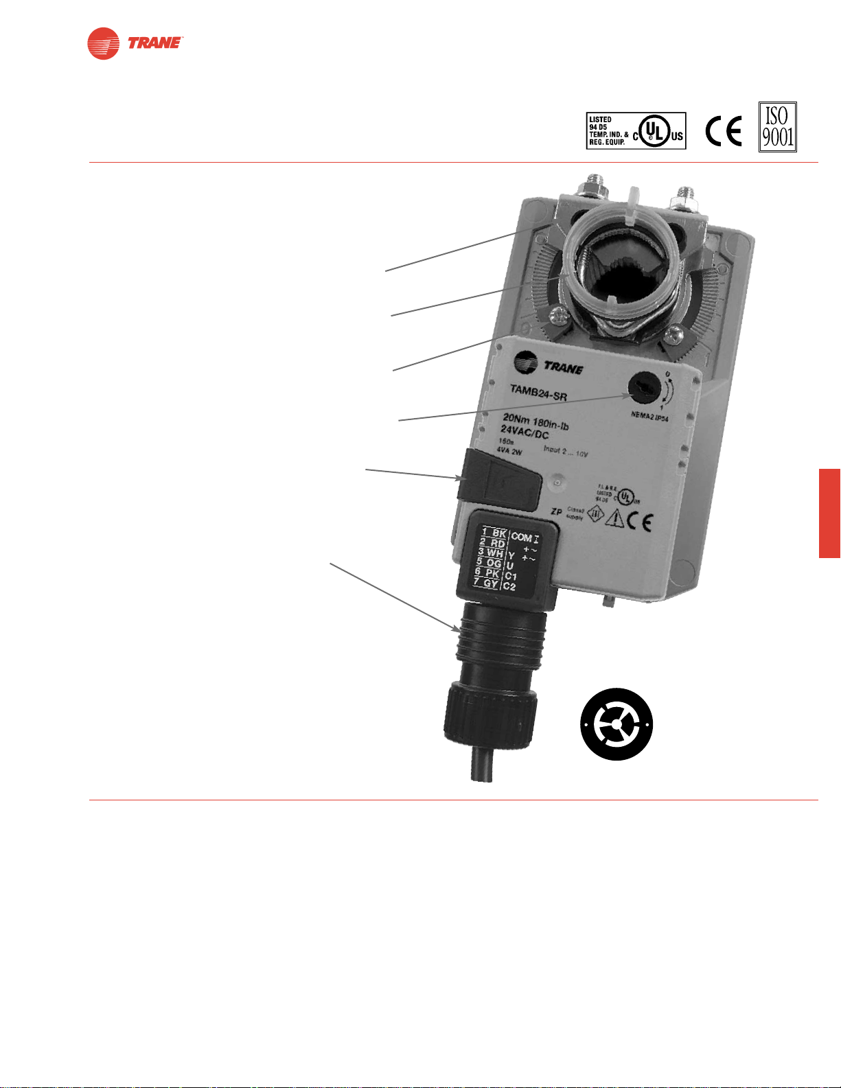
81
I20683 - Subject to change.
TAMB
● Brushless DC motor for added accuracy and
controllability.
● Cut labor costs with simple direct coupling.
● Self-centers on 1/2", 3/4", and 1.05" jackshafts with
standard clamp.
● Check damper position with clear position indicator.
● Don’t worry about actuator burn-out;
It is overload proof throughout rotation.
● Enjoy added flexibility with easy mechanical stops
to adjust angle of rotation.
● Need to change control direction? Do it easily with
a simple switch.
● Easily accessible manual override button helps
you pre-tension damper blades.
● Auxiliary switch and feedback potentiometer add-ons
mount directly on clamp, includes conduit connector.
● Standard 3ft plenum rated cable and conduit
connector provided.
TAMB Series Direct Coupled Actuator
The T rane Difference
● Low Installation and Life-Cycle Cost.
Easy installation. Accuracy and repeatability.
Low power consumption. No maintenance.
●
Long Service Life.
Components tested before assembly. Every product tested before shipment.
30+ years direct coupled actuator design.
©
H
A
L
O
M
O
B
r
u
s
h
l
e
s
s
D
C
M
o
t
o
r
A CLOSER LOOK…
Page 82
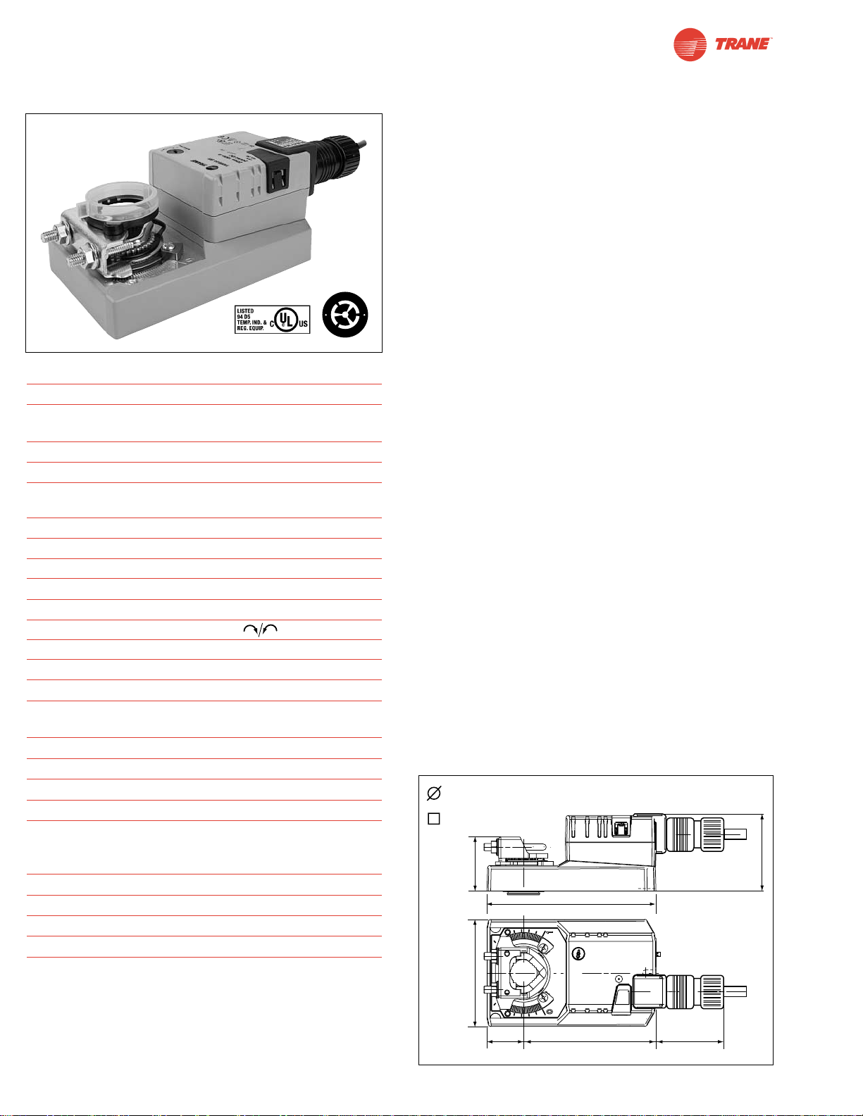
82
I20683 - Subject to change.
TAMB24-3
On/Off-Floating Point Control, Non-Spring Return, Direct Coupled, 24 V
Technical Data TAMB24-3
Power Supply 24 VAC ± 20% 50/60 Hz
24 VDC ± 10%
Power Consumption 2.5 W (0.2 W)
Transformer Sizing 5.5 VA (Class 2 power source)
Electrical Connection 3 ft, 18 GA plenum rated cable
1/2” conduit connector
Overload Protection electronic throughout 0° to 95° rotation
Control on/off, floating point
Input Impedance 600Ω
Angle of Rotation max. 95°, adjust. with mechanical stop
Torque 180 in-lb [20 Nm]
Direction of Rotation reversible with switch
Position Indication reflective visual indicator (snap-on)
Manual Override external push button
Running Time 95 seconds, constant independent of load
Humidity 5 to 95% RH non condensing
(EN 60730-1)
Ambient Temperature -22°F to +122°F [-30°C to +50°C]
Storage Temperature -40°F to +176°F [-40°C to +80°C]
Housing NEMA 2/IP54
Housing Material UL94-5VA
Agency Listings cULus acc. to UL 60730-1/-2-14 and
CAN/CSA C22.2 No.24, CE according
to 73 / 23 / EEC
Noise Level <45dB(A)
Servicing maintenance free
Quality Standard ISO 9001
Weight 2.2 lbs [1000 Kg] TAMB24-3
Torque min. 180 in-lb for control of damper
surfaces up to 45 sq ft.
Application
For on/off and floating point control of dampers in HVAC
systems. Actuator sizing should be done in accordance with
the damper manufacturer’s specifications.
The actuator is mounted directly to a damper shaft up to 1.05”
in diameter by means of its universal clamp, self-centered
default. A crankarm and several mounting brackets are
available for applications where the actuator cannot be direct
coupled to the damper shaft.
Operation
The actuator is not provided with and does not require any
limit switches, but is electronically protected against overload.
The anti-rotation strap supplied with the actuator will prevent
lateral movement.
The TAMB series provides 95° of rotation and a visual
indicator indicates position of the actuator. When reaching
the damper or actuator end position, the actuator automatically stops. The gears can be manually disengaged with a
button on the actuator cover.
The TAMB24-3… actuators use a sensorless brushless DC
motor, which is controlled by an Application Specific
Integrated Circuit (ASIC). The ASIC monitors and controls
the actuator’s rotation and provides a digital rotation sensing
(DRS) function to prevent damage to the actuator in a stall
condition. Power consumption is reduced in holding mode.
Add on auxiliary switches or feedback potentiometers are
easily fastened directly onto the actuator body for signaling
and switching functions.
For all accessories, see pages 110 and 132.
Dimensions
(All numbers in brackets are in millimeters.)
D122
O
M
L
©
O
A
H
B
r
r
o
u
t
s
o
h
M
l
e
s
C
s
D
1/2” to 1.05” [13 to 26]
1/2” Centered (Default)
3/8” to 11/16” [10 to 17]
2.2” [56]
2.49” [63.4]
5.47” [139]
3.46” [88]
1.18”
[30]
4.3” [109]
2” [50.8]
Page 83
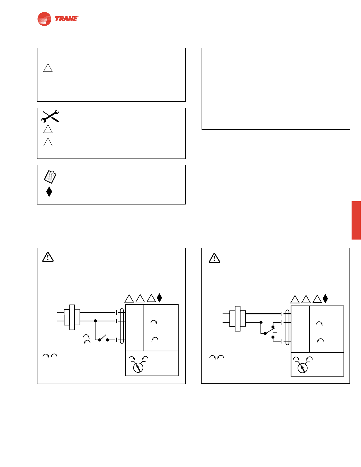
83
I20683 - Subject to change.
TAMB
TAMB24-3
On/Off-Floating Point Control, Non-Spring Return, Direct Coupled, 24 V
TAMB24-3 - Typical Specification:
Floating point, on/off control damper actuators shall be
electronic direct-coupled type, which require no crankarm
and linkage and be capable of direct mounting to a shaft
up to 1.05” diameter. Actuators shall have brushless DC
motor technology and be protected from overload at all
angles of rotation. Actuators shall have reversing switch
and manual override on the cover. Run time shall be
constant and independent of torque. Actuators are cULus
listed, and be manufactured under ISO 9001 International
Quality Control Standards. Actuators shall be as
manufactured by Belimo.
W481
W482
On/Off
Floating Point or On/Off control
Wiring Diagrams
2
Equipment damage!
Up to 4 actuators may be connected in parallel.
With 4 actuators wired to one 500Ω resistor.
Power consumption must be observed and input
impedance must be observed.
Meets cULus or UL and CSA requirements without
the need of an electrical ground connection.
3
5
Actuator may also be powered by 24 VDC.
Actuators with plenum rated cable do not have
numbers on wires; use color codes instead.
Actuators with appliance cables use numbers.
CAUTION
INSTALLATION NOTES
APPLICATION NOTES
WARNING
Live Electrical Components!
During installation, testing, servicing and troubleshooting of this product, it maybe
necessary to work with live electrical components. Have a qualified licensed electrician
or other individual who has been properly trained in handling live electrical components
perform these tasks. Failure to follow all electrical safety precautions when exposed
to live electrical components could result in death or serious injury.
24 VAC Transformer
Line
Volts
a open
a closed
The indication of direction
is valid for switch position 1.
5
3
2
Blk (1) Common
Red (2) +
a
Wht (3) +
1 0
–
TAMB24-3
WARNING
Live Electrical Components!
During installation, testing, servicing and troubleshooting of this product, it maybe
necessary to work with live electrical components. Have a qualified licensed electrician
or other individual who has been properly trained in handling live electrical components
perform these tasks. Failure to follow all electrical safety precautions when exposed
to live electrical components could result in death or serious injury.
5
3
24 VAC Transformer
Line
Volts
The indication of direction
is valid for switch position 1.
2
Blk (1) Common
Red (2) +
Wht (3) +
1 0
TAMB24-3
–
Page 84
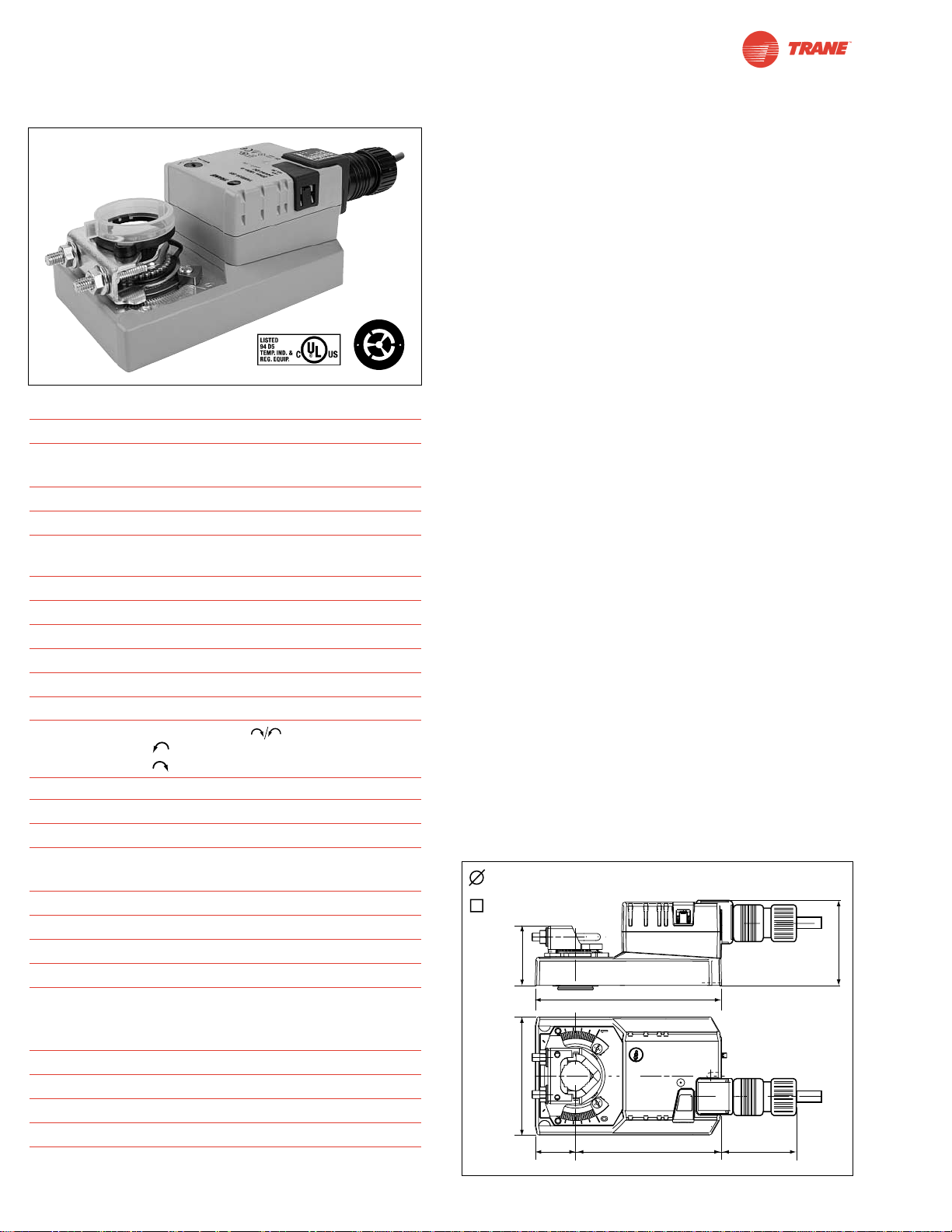
84
I20683 - Subject to change.
TAMB24-SR
Proportional Control, Non-Spring Return, Direct Coupled, 24V, for 2 to 10 VDC and 4 to 20 mA
Technical Data TAMB24-SR
Power Supply 24 VAC ± 20% 50/60 Hz
24 VDC ± 10%
Power Consumption 2.5 W (0.4 W)
Transformer Sizing 5 VA (Class 2 power source)
Electrical Connection 3 ft, 18 GA plenum rated cable
1/2” conduit connector
Overload Protection electronic throughout 0° to 95° rotation
Operating Range Y 2 to 10 VDC, 4 to 20 mA
Input Impedance 100kΩ (0.1 mA), 500Ω
Feedback Output U 2 to 10 VDC (max 0.5 mA)
Angle of Rotation max. 95°, adjust. with mechanical stop
Torque 180 in-lb [20 Nm]
Direction of Rotation
reversible with switch. Actuator will move:
=CCW with decreasing control signal (10➞2V)
=CW with decreasing control signal (10➞2V)
Position Indication reflective visual indicator (snap-on)
Manual Override external push button
Running Time 95 seconds, constant independent of load
Humidity 5 to 95% RH non condensing
(EN 60730-1)
Ambient Temperature -22°F to +122°F [-30°C to +50°C]
Storage Temperature -40°F to +176°F [-40°C to +80°C]
Housing NEMA 2/IP54
Housing Material UL94-5VA
Agency Listings cULus acc. to UL 60730-1/-2-14 and
CAN/CSA C22.2 No.24, CE according
to 73 / 23 / EEC
Noise Level <45dB(A)
Servicing maintenance free
Quality Standard ISO 9001
Weight 2.2 lbs [1000 Kg]
Torque min. 180 in-lb for control of damper
surfaces up to 45 sq ft.
Application
For proportional modulation of dampers in HVAC systems.
Actuator sizing should be done in accordance with the
damper manufacturer’s specifications.
The actuator is mounted directly to a damper shaft up to 1.05”
in diameter by means of its universal clamp, 1/2” self-centered
default. A crankarm and several mounting brackets are
available for applications where the actuator cannot be direct
coupled to the damper shaft.
The actuator operates in response to a 2 to 10 VDC, or with
the addition of a 500Ω resistor, a 4 to 20 mA control input
from an electronic controller or positioner. A 2 to 10 VDC
feedback signal is provided for position indication or
master-slave applications.
Operation
The actuator is not provided with and does not require any
limit switches, but is electronically protected against overload.
The anti-rotation strap supplied with the actuator will prevent
lateral movement.
The TAMB series provides 95° of rotation and a visual indicator
indicates position of the actuator. When reaching the damper or
actuator end position, the actuator automatically stops. The gears
can be manually disengaged with a button on the actuator cover.
The TAMB24-SR… actuators use a sensorless brushless DC
motor, which is controlled by an Application Specific
Integrated Circuit (ASIC). The ASIC monitors and controls the
actuator’s rotation and provides a digital rotation sensing
(DRS) function to prevent damage to the actuator in a stall
condition. Power consumption is reduced in holding mode.
Add on auxiliary switches or feedback potentiometers are
easily fastened directly onto the actuator body for signaling
and switching functions
For all accessories, see pages 110 and 132.
Dimensions
(All numbers in brackets are in millimeters.)
D122
O
M
L
©
O
A
H
B
r
r
o
u
t
s
o
h
M
l
e
s
C
s
D
1/2” to 1.05” [13 to 26]
1/2” Centered (Default)
3/8” to 11/16” [10 to 17]
2.2” [56]
5.47” [139]
3.46” [88]
1.18”
[30]
4.3” [109]
2.49” [63.4]
2” [50.8]
Page 85
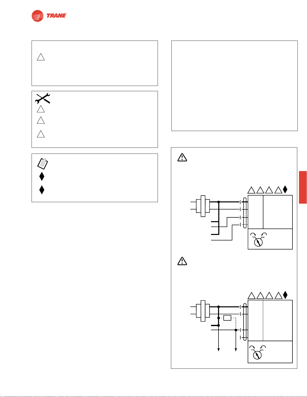
85
I20683 - Subject to change.
TAMB
TAMB24-SR
Proportional Control, Non-Spring Return, Direct Coupled, 24V, for 2 to 10 VDC and 4 to 20 mA
TAMB24-SR - Typical Specification:
Proportional control damper actuators shall be electronic
direct-coupled type, which require no crankarm and linkage
and be capable of direct mounting to a shaft up to 1.05”
diameter. Actuators must provide proportional damper
control in response to a 2 to 10 VDC or, with the addition
of a 500Ω resistor, a 4 to 20 mA control input from an
electronic controller or positioner. Actuators shall have
brushless DC motor technology and be protected from
overload at all angles of rotation. Actuators shall have
reversing switch and manual override on the cover. Run
time shall be constant and independent of torque. A 2 to
10 VDC feedback signal shall be provided for position
indication. Actuators are cULus listed, and be
manufactured under ISO 9001 International Quality Control
Standards. Actuators shall be as manufactured by Belimo.
2 to 10 VDC and 4 to 20 mA control of TAMB24-SR
2
Equipment damage!
Up to 4 actuators may be connected in parallel.
With 4 actuators wired to one 500Ω resistor.
Power consumption must be observed and input
impedance must be observed.
Meets cULus or UL and CSA requirements without
the need of an electrical ground connection.
The ZG-R01 500Ω resistor converts the 4 to 20 mA
control signal to 2 to 10 VDC.
3
5
6
Actuator may also be powered by 24 VDC.
Actuators with plenum rated cable do not have
numbers on wires; use color codes instead.
Actuators with appliance cables use numbers.
Only connect common to neg. (—) leg of control
circuits.
Wiring Diagrams
W483
CAUTION
INSTALLATION NOTES
APPLICATION NOTES
WARNING
Live Electrical Components!
During installation, testing, servicing and troubleshooting of this product, it maybe
necessary to work with live electrical components. Have a qualified licensed electrician
or other individual who has been properly trained in handling live electrical components
perform these tasks. Failure to follow all electrical safety precautions when exposed
to live electrical components could result in death or serious injury.
5 6
3
24 VAC Transformer
2
Line
Volts
Control Signal
2 to 10 VDC
2 to 10 VDC
Feedback Signal
(–)
(+)
(–)
(+)
Blk (1) Common
Red (2) Hot +
Wht (3) Y Input, 2 to 10V
Org (5) U Output, 2 to 10V
1 0
–
TAMB24-SR
WARNING
Live Electrical Components!
During installation, testing, servicing and troubleshooting of this product, it maybe
necessary to work with live electrical components. Have a qualified licensed electrician
or other individual who has been properly trained in handling live electrical components
perform these tasks. Failure to follow all electrical safety precautions when exposed
to live electrical components could result in death or serious injury.
24 VAC Transformer
Line
Volts
2
Blk (1) Common
Red (2) Hot +
5 6
3
–
Ω
4 to 20 mA
Control Signal
(–)
(+)
500Ω
To other
actuators
Wht (3) Y Input, 2 to 10V
Org (5) U Output, 2 to 10V
1 0
TAMB24-SR
Page 86

86
I20683 - Subject to change.
TNMB24-3
TNMB24-SR
TNMB Series - At A Glance
Pages 88 90
Basic Product ●●
Torque 90 in-lb [10 Nm] ●●
Angle of Rotation 95 degrees ●●
Power Supply 24 VAC/DC ●●
Control Input On/Off, Floating Point ●
2 to 10 VDC (4 to 20mA) ●
Feedback None ●
2 to 10 VDC ●
Running Time 95 seconds ●●
Wiring Plenum Rated Cable ●●
Conduit Fitting ●●
Auxiliary Switch Add-on ●●
Installation and Operation… (page 99).
*Based on 4 in-lb/ft2damper torque loading. Parallel blade. No edge seals.
TNMB Series Direct Coupled Actuator
Minimum 90 in-lb Torque
● For damper areas up to 22 sq-ft*
©
H
A
L
O
M
O
B
r
u
s
h
l
e
s
s
D
C
M
o
t
o
r
All Actuators
have BDCM
Page 87
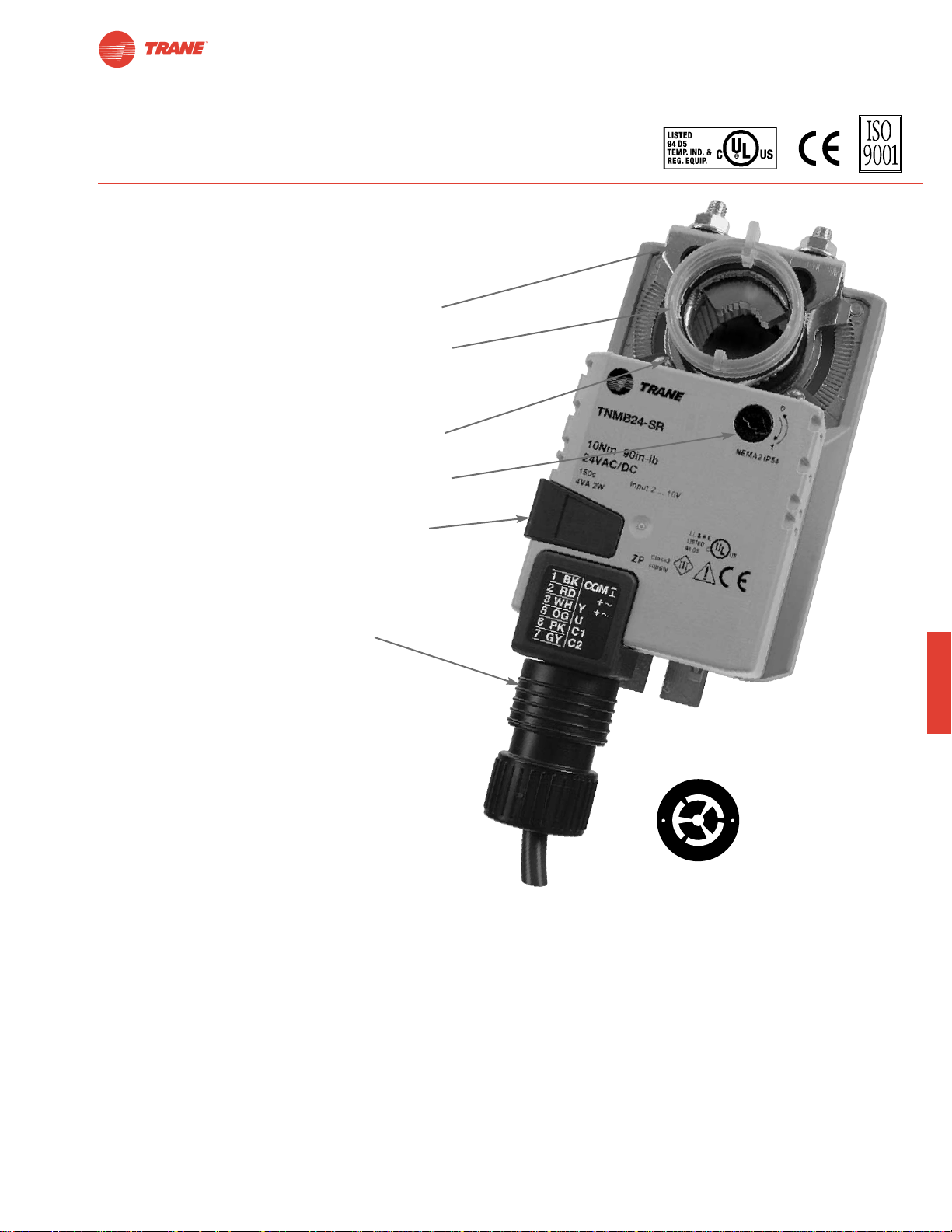
87
I20683 - Subject to change.
TNMB
TNMB Series Direct Coupled Actuator
● Brushless DC motor for added accuracy and
controllability.
● Cut labor costs with simple direct coupling.
● Self-centers on 1/2", 3/4", and 1.05" jackshafts with
standard clamp.
● Check damper position with clear position indicator.
● Don’t worry about actuator burn-out;
It is overload proof throughout rotation.
● Enjoy added flexibility with easy mechanical stops
to adjust angle of rotation.
● Need to change control direction? Do it easily with
a simple switch.
● Easily accessible manual override button helps
you pre-tension damper blades.
● Auxiliary switch and feedback potentiometer add-ons
mount directly on clamp, Includes conduit connector.
● Standard 3ft plenum rated cable and conduit
connector provided.
The T rane Difference
● Low Installation and Life-Cycle Cost.
Easy installation. Accuracy and repeatability.
Low power consumption. No maintenance.
●
Long Service Life.
Components tested before assembly. Every product tested before shipment.
30+ years direct coupled actuator design.
©
H
A
L
O
M
O
B
r
u
s
h
l
e
s
s
D
C
M
o
t
o
r
A CLOSER LOOK…
Page 88
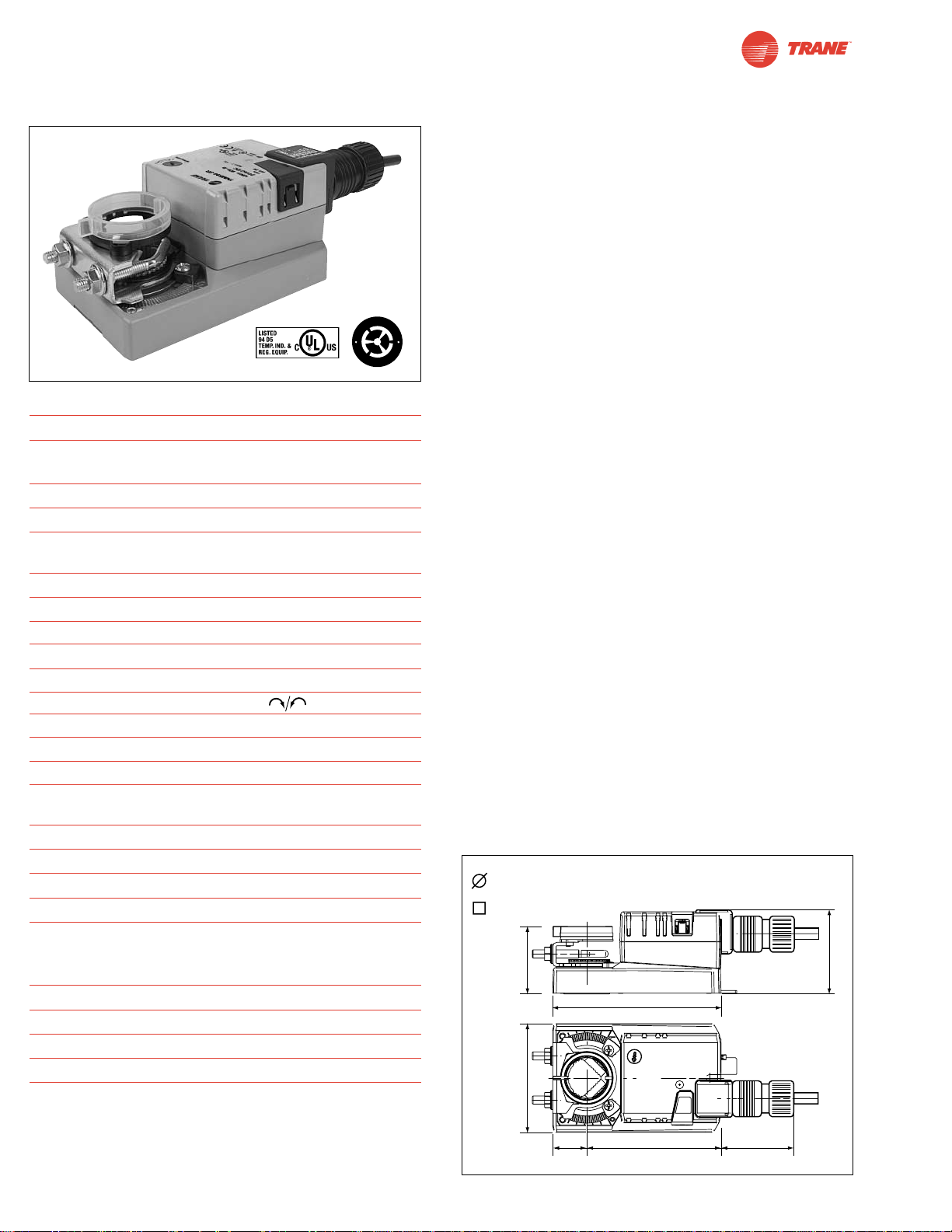
88
I20683 - Subject to change.
TNMB24-3
On/Off-Floating Point Control, Non-Spring Return, Direct Coupled, 24 V
Technical Data TNMB24-3
Power Supply 24 VAC ± 20% 50/60 Hz
24 VDC ± 10%
Power Consumption 2 W (0.2 W)
Transformer Sizing 4 VA (Class 2 power source)
Electrical Connection 3 ft, 18 GA plenum rated cable
1/2” conduit connector
Overload Protection electronic throughout 0° to 95° rotation
Control on/off, floating point
Input Impedance 600Ω
Angle of Rotation max. 95°, adjust. with mechanical stop
Torque 90 in-lb [10 Nm]
Direction of Rotation reversible with switch
Position Indication reflective visual Indicator (snap-on)
Manual Override external push button
Running Time 95 seconds, constant independent of load
Humidity 5 to 95% RH non condensing
(EN 60730-1)
Ambient Temperature -22°F to +122°F [-30°C to +50°C]
Storage Temperature -40°F to +176°F [-40°C to +80°C]
Housing NEMA 2/IP54
Housing Material UL94-5VA
Agency Listings cULus acc. to UL 60730-1/-2-14 and
CAN/CSA C22.2 No.24, CE according
to 73 / 23 / EEC
Noise Level <45dB(A)
Servicing maintenance free
Quality Standard ISO 9001
Weight 1.7 lbs [0.75 Kg]
Torque min. 90 in-lb for control of damper
surfaces up to 22 sq ft.
Application
For on/off and floating point control of dampers in HVAC
systems. Actuator sizing should be done in accordance with
the damper manufacturer’s specifications.
The actuator is mounted directly to a damper shaft up to 1.05"
in diameter by means of its universal clamp, 1/2” self-centered
default. A crankarm and several mounting brackets are
available for applications where the actuator cannot be direct
coupled to the damper shaft.
Operation
The actuator is not provided with and does not require any limit
switches, but is electronically protected against overload. The
anti-rotation strap supplied with the actuator will prevent lateral
movement.
The TNMB series provides 95° of rotation and a visual
indicator indicates position of the actuator. When reaching the
damper or actuator end position, the actuator automatically
stops. The gears can be manually disengaged with a button
on the actuator cover.
The TNMB24-3… actuators use a sensorless brushless DC
motor, which is controlled by an Application Specific Integrated
Circuit (ASIC). The ASIC monitors and controls the actuator’s
rotation and provides a digital rotation sensing (DRS) function
to prevent damage to the actuator in a stall condition. Power
consumption is reduced in holding mode.
Add on auxiliary switches or feedback potentiometers are
easily fastened directly onto the actuator body for signaling
and switching functions.
For all accessories, see pages 110 and 132.
Dimensions
(All numbers in brackets are in millimeters.)
D121
O
M
L
©
O
A
H
B
r
r
o
u
t
s
o
h
M
l
e
s
C
s
D
1/2” to 1.05” [13 to 26]
1/2” Centered (Default)
3/8” to 11/16” [10 to 17]
2.36” [60]
3.15” [80]
2.42” [61.4]
4.88” [124]
0.98”
[25]
3.9” [99]
2” [50.8]
Page 89
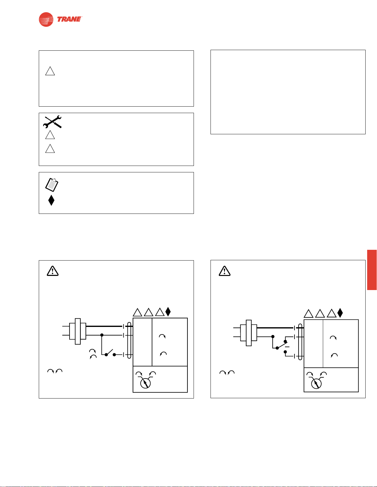
TNMB
I20683 - Subject to change.
Wiring Diagrams
TNMB24-3
On/Off-Floating Point Control, Non-Spring Return, Direct Coupled, 24 V
TNMB24-3 - Typical Specification:
Floating point, on/off control damper actuators shall be
electronic direct-coupled type, which require no crankarm
and linkage and be capable of direct mounting to a shaft up
to 1.05” diameter. Actuators shall have brushless DC motor
technology and be protected from overload at all angles of
rotation. Actuators shall have reversing switch and manual
override on the cover. Run time are
constant and independent of torque. Actuators are cULus
listed, and be manufactured under ISO 9001 International
Quality Control Standards. Actuators shall
be as manufactured by Belimo.
W497
W498
On/Off Floating point or On/Off control
89
2
Equipment damage!
Up to 4 actuators may be connected in parallel.
With 4 actuators wired to one 500Ω resistor.
Power consumption must be observed and input
impedance must be observed.
Meets cULus or UL and CSA requirements without
the need of an electrical ground connection.
3
5
Actuator may also be powered by 24 VDC.
Actuators with plenum rated cable do not have
numbers on wires; use color codes instead.
Actuators with appliance cables use numbers.
CAUTION
INSTALLATION NOTES
APPLICATION NOTES
WARNING
Live Electrical Components!
During installation, testing, servicing and troubleshooting of this product, it maybe
necessary to work with live electrical components. Have a qualified licensed electrician
or other individual who has been properly trained in handling live electrical components
perform these tasks. Failure to follow all electrical safety precautions when exposed
to live electrical components could result in death or serious injury.
5
3
24 VAC Transformer
Line
Volts
a open
a
a closed
The indication of direction
2
Blk (1) Common
Red (2) +
Wht (3) +
1 0
is valid for switch position 1.
WARNING
Live Electrical Components!
During installation, testing, servicing and troubleshooting of this product, it maybe
necessary to work with live electrical components. Have a qualified licensed electrician
or other individual who has been properly trained in handling live electrical components
perform these tasks. Failure to follow all electrical safety precautions when exposed
to live electrical components could result in death or serious injury.
24 VAC Transformer
–
Line
Volts
The indication of direction
is valid for switch position 1.
TNMB24-3
5
3
2
Blk (1) Common
Red (2) +
Wht (3) +
1 0
TNMB24-3
–
Page 90
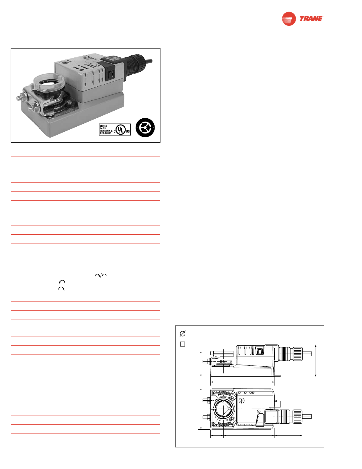
90
I20683 - Subject to change.
TNMB24-SR
Proportional Control, Non-Spring Return, Direct Coupled, 24V, for 2 to 10 VDC and 4 to 20 mA
Technical Data TNMB24-SR
Power Supply 24 VAC ± 20% 50/60 Hz
24 VDC ± 10%
Power Consumption 2.5 W (0.4 W)
Transformer Sizing 5 VA (Class 2 power source)
Electrical Connection 3 ft, 18 GA plenum rated cable
1/2” conduit connector
Overload Protection electronic throughout 0° to 95° rotation
Operating Range Y 2 to 10 VDC, 4 to 20 mA
Input Impedance 100 kΩ (0.1 mA), 500Ω
Feedback Output U 2 to 10 VDC (max 0.5 mA)
Angle of Rotation max. 95°, adjust. with mechanical stop
Torque 90 in-lb [10 Nm]
Direction of Rotation
reversible with switch. Actuator will move:
=CCW with decreasing control signal (10➞2V)
=CW with decreasing control signal (10➞2V)
Position Indication reflective visual Indicator (snap-on)
Manual Override external push button
Running Time 95 seconds, constant independent of load
Humidity 5 to 95% RH non condensing
(EN 60730-1)
Ambient Temperature -22°F to +122°F [-30°C to +50°C]
Storage Temperature -40°F to +176°F [-40°C to +80°C]
Housing NEMA 2/IP54
Housing Material UL94-5VA
Agency Listings cULus acc. to UL 60730-1/-2-14 and
CAN/CSA C22.2 No.24, CE according
to 73 / 23 / EEC
Noise Level <45dB(A)
Servicing maintenance free
Quality Standard ISO 9001
Weight 1.7 lbs [0.75 Kg]
Torque min. 90 in-lb for control of damper
surfaces up to 22 sq ft.
Application
For proportional modulation of dampers in HVAC systems.
Actuator sizing should be done in accordance with the
damper manufacturer’s specifications.
The actuator is mounted directly to a damper shaft up to 1.05"
in diameter by means of its universal clamp, 1/2” self centered
default. A crankarm and several mounting brackets are
available for applications where the actuator cannot be direct
coupled to the damper shaft.
The actuator operates in response to a 2 to 10 VDC, or with
the addition of a 500Ω resistor, a 4 to 20 mA control input
from an electronic controller or positioner. A 2 to 10 VDC
feedback signal is provided for position indication or
master-slave applications.
Operation
The actuator is not provided with and does not require any
limit switches, but is electronically protected against overload.
The anti-rotation strap supplied with the actuator will prevent
lateral movement.
The TNMB series provides 95° of rotation and a visual indicator indicates position of the actuator. When reaching the
damper or actuator end position, the actuator automatically
stops. The gears can be manually disengaged with a button
on the actuator cover.
The TNMB24-SR… actuators use a sensorless brushless DC
motor, which is controlled by an Application Specific
Integrated Circuit (ASIC). The ASIC monitors and controls the
actuator’s rotation and provides a digital rotation sensing
(DRS) function to prevent damage to the actuator in a stall
condition.Power consumption is reduced in holding mode.
Add on auxiliary switches or feedback potentiometers are
easily fastened directly onto the actuator body for signaling
and switching functions
For all accessories, see pages 110 and 132.
Dimensions
(All numbers in brackets are in millimeters.)
D121
O
M
L
©
O
A
H
B
r
r
o
u
t
s
o
h
M
l
e
s
C
s
D
1/2” to 1.05” [13 to 26]
1/2” Centered (Default)
3/8” to 11/16” [10 to 17]
2.36” [60]
4.88” [124]
3.15” [80]
0.98”
[25]
3.9” [99]
2.42” [61.4]
2” [50.8]
Page 91
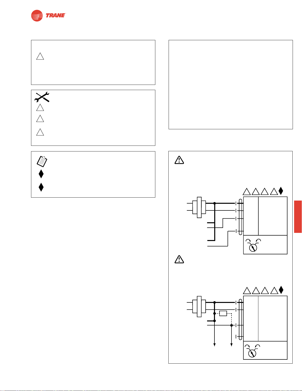
91
I20683 - Subject to change.
TNMB
TNMB24-SR
Proportional Control, Non-Spring Return, Direct Coupled, 24V, for 2 to 10 VDC and 4 to 20 mA
TNMB24-SR - Typical Specification:
Proportional control damper actuators shall be electronic
direct-coupled type, which require no crankarm and linkage
and be capable of direct mounting to a shaft up to 1.05”
diameter. Actuators must provide proportional damper
control in response to a 2 to 10 VDC or, with the addition
of a 500Ω resistor, a 4 to 20 mA control input from an
electronic controller or positioner. Actuators shall have
brushless DC motor technology and be protected from
overload at all angles of rotation. Actuators shall have
reversing switch and manual override on the cover. Run
time shall be constant and independent of torque. A 2 to
10 VDC feedback signal shall be provided for position
indication. Actuators are cULus listed, and be
manufactured under ISO 9001 International Quality Control
Standards. Actuators shall be as manufactured by Belimo.
Wiring Diagrams
W499
2 to 10 VDC and 4 to 20 mA control of TNMB24-SR
2
Equipment damage!
Up to 4 actuators may be connected in parallel.
With 4 actuators wired to one 500Ω resistor.
Power consumption must be observed and input
impedance must be observed.
Meets cULus or UL and CSA requirements without
the need of an electrical ground connection.
The ZG-R01 500Ω resistor converts the 4 to 20 mA
control signal to 2 to 10 VDC.
3
5
6
Actuator may also be powered by 24 VDC.
Actuators with plenum rated cable do not have
numbers on wires; use color codes instead.
Actuators with appliance cables use numbers.
Only connect common to neg. (—) leg of control
circuits.
CAUTION
INSTALLATION NOTES
APPLICATION NOTES
WARNING
Live Electrical Components!
During installation, testing, servicing and troubleshooting of this product, it maybe
necessary to work with live electrical components. Have a qualified licensed electrician
or other individual who has been properly trained in handling live electrical components
perform these tasks. Failure to follow all electrical safety precautions when exposed
to live electrical components could result in death or serious injury.
5 6
3
24 VAC Transformer
2
Line
Volts
Control Signal
2 to 10 VDC
2 to 10 VDC
Feedback Signal
(–)
(+)
(–)
(+)
Blk (1) Common
Red (2) Hot +
Wht (3) Y Input, 2 to 10V
Org (5) U Output, 2 to 10V
1 0
–
TNMB24-SR
WARNING
Live Electrical Components!
During installation, testing, servicing and troubleshooting of this product, it maybe
necessary to work with live electrical components. Have a qualified licensed electrician
or other individual who has been properly trained in handling live electrical components
perform these tasks. Failure to follow all electrical safety precautions when exposed
to live electrical components could result in death or serious injury.
5 6
3
24 VAC Transformer
Line
Volts
2
Blk (1) Common
Red (2) Hot +
–
Ω
4 to 20 mA
Control Signal
(–)
(+)
500Ω
To other
actuators
Wht (3) Y Input, 2 to 10V
Org (5) U Output, 2 to 10V
10
TNMB24-SR
Page 92

92
I20683 - Subject to change.
TLMB24-3
TLMB24-3-T
TLMB24-SR
TLMB24-SR-T
TLMB Series Direct Coupled Actuator
Versatile and Powerful
● Minimum 45 in-lb torque in a compact package.
For damper areas up to 11 sq-ft*
©
H
A
L
O
M
O
B
r
u
s
h
l
e
s
s
D
C
M
o
t
o
r
All Actuators
have BDCM
TLMB Series - At A Glance
Pages 94 94 96 96
Basic Product ●●●●
Torque 45 in-lb [5 Nm] ●●●●
Angle of Rotation 95 degrees ●●●●
Power Supply 24 VAC/DC ●●●●
Control Input On/Off, Floating Point ●●
2 to 10 VDC (4 to 20mA) ●●
Feedback None ●● ●
2 to 10 VDC ●
Running Time 95 seconds ●●●●
Wiring Plenum Rated Cable ●●
Terminal Strip ●●
Conduit Fitting ●●
Auxiliary Switch Add-on ●●●●
Installation and Operation… (page 99).
*Based on 4 in-lb/ft2damper torque loading. Parallel blade. No edge seals.
Page 93
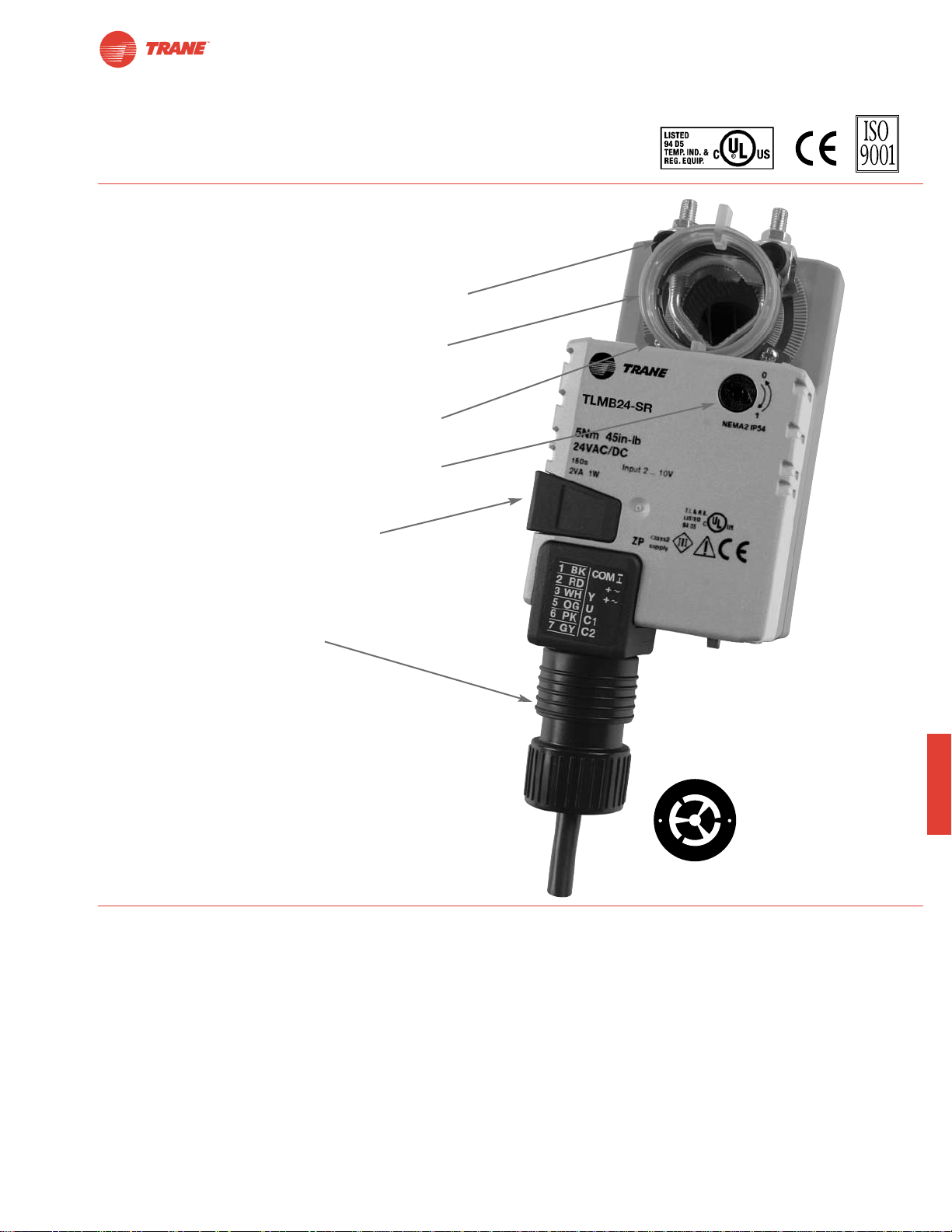
93
I20683 - Subject to change.
TLMB
TLMB Series Direct Coupled Actuator
● Brushless DC motor for added accuracy and
controllability.
● Cut labor costs with simple direct coupling.
● Self-centers on 5/8" jackshafts with standard clamp or
3/4" with accessory clamp.
● Check damper position with clear position indicator.
● Don’t worry about actuator burn-out;
It is overload proof throughout rotation.
● Enjoy added flexibility with easy mechanical stops
to adjust angle of rotation.
● Need to change control direction? Do it easily with
a simple switch.
● Easily accessible manual override button
helps you pre-tension damper blades.
● Auxiliary switch and feedback potentiometer add-ons
mount directly on clamp, includes conduit connector.
● Standard 3ft plenum rated cable and conduit
connector provided.
The T rane Difference
● Low Installation and Life-Cycle Cost.
Easy installation. Accuracy and repeatability.
Low power consumption. No maintenance.
●
Long Service Life.
Components tested before assembly. Every product tested before shipment.
30+ years direct coupled actuator design.
©
H
A
L
O
M
O
B
r
u
s
h
l
e
s
s
D
C
M
o
t
o
r
A CLOSER LOOK…
Bulk Packaging Offers Big
Value for Large jobs,
Stocking Orders.
Page 94
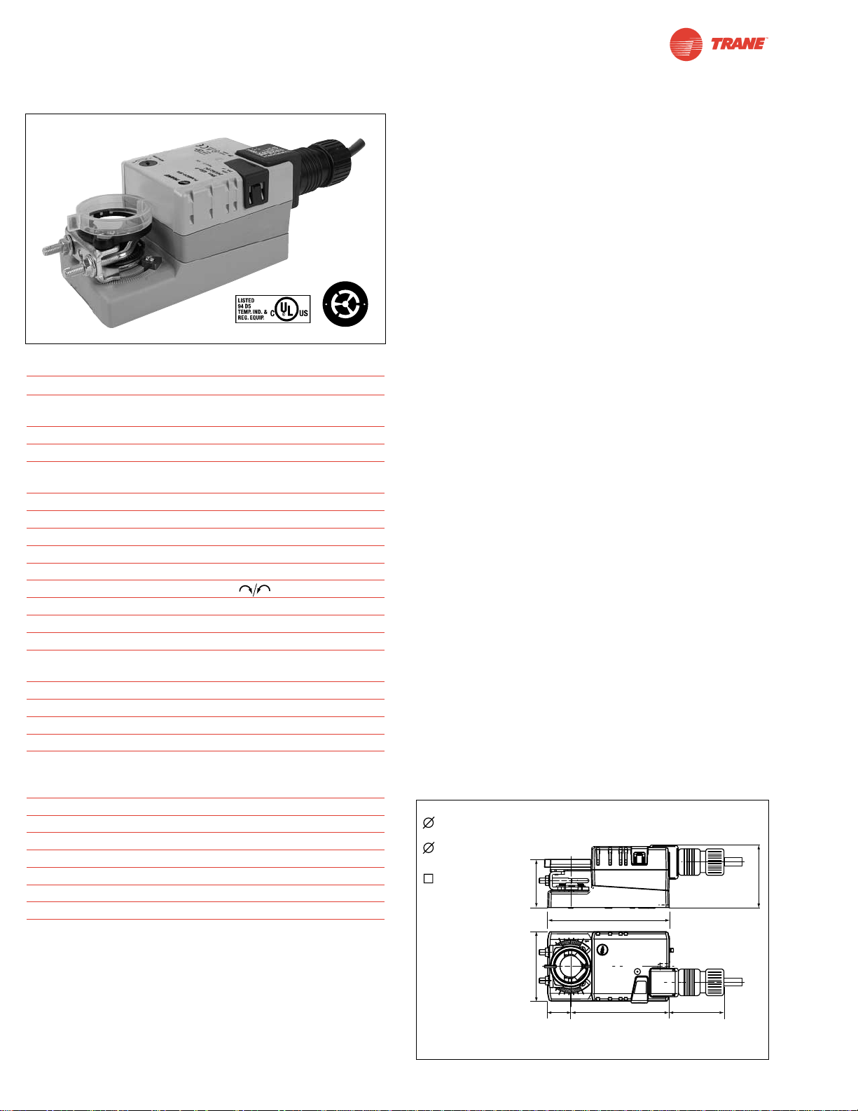
94
I20683 - Subject to change.
Technical Data TLMB24-3… on/off-floating
Power Supply 24 VAC ± 20% 50/60 Hz
24 VDC ± 10%
Power Consumption 1.5 W (0.2 W)
Transformer Sizing 3 VA (Class 2 power source)
Electrical Connection 3 ft, 18 GA plenum rated cable
1/2” conduit connector
Overload Protection electronic throughout 0° to 95° rotation
Control on/off, floating point
Input Impedance 600Ω
Angle of Rotation max. 95°, adjust. with mechanical stop
Torque 45 in-lb [5 Nm]
Direction of Rotation reversible with switch
Position Indication reflective visual indicator (snap-on)
Manual Override external push button
Running Time 95 seconds, constant independent of load
Humidity 5 to 95% RH non condensing
(EN 60730-1)
Ambient Temperature -22°F to +122°F [-30°C to +50°C]
Storage Temperature -40°F to +176°F [-40°C to +80°C]
Housing NEMA 2/IP54
Housing Material UL94-5VA
Agency Listings cULus acc. to UL 60730-1/-2-14 and
CAN/CSA C22.2 No.24, CE according to
73 / 23 / EEC
Noise Level <35dB(A)
Servicing maintenance free
Quality Standard ISO 9001
Weight 1.1lbs [0.5 Kg],
TLMB24-3-T
Electrical connection Screw terminal (for 26 to 14 GA wire)
Housing NEMA 1/IP20
TLMB24-3 (-T)
On/Off-Floating Point Control, Non-Spring Return, Direct Coupled, 24 V
Torque min. 45 in-lb for control of damper
surfaces up to 11 sq ft.
TLMB24-3
TLMB24-3-T
TLMB24-3-T.1 (bulk)
Application
For on-off and floating point control of dampers in HVAC
systems. Actuator sizing should be done in accordance with
the damper manufacturer’s specifications.
The actuator is mounted directly to a damper shaft from 1/4”
up to 5/8” in diameter by means of its standard universal
clamp. Shafts up to 3/4” diameter can be accommodated by
an accessory clamp.
Operation
The actuator is not provided with and does not require any
limit switches, but is electronically protected against overload.
The anti-rotation strap supplied with the actuator will prevent
lateral movement.
The TLMB series provides 95° of rotation and a visual
indicator which indicates position of the actuator. When
reaching the damper or actuator end position, the actuator
automatically stops. The gears can be disengaged with
manual release on the actuator cover.
The TLMB24-3… actuators use a sensorless brushless DC
motor, which is controlled by an Application Specific Integrated
Circuit (ASIC). The ASIC monitors and controls the actuator’s
rotation and provides a digital rotation sensing (DRS) function
to prevent damage to the actuator in a stall condition. Power
consumption is reduced in holding mode.
Add on auxiliary switches or feedback potentiometers are easily
fastened directly onto the actuator body for signaling and
switching functions.
For all accessories, see pages 110 and 132.
Dimensions
(All numbers in brackets are in millimeters.)
D120
O
M
L
©
O
A
H
B
r
r
o
u
t
s
o
h
M
l
e
s
C
s
D
1/4” to 5/8” [6 to 16]
5/8" Centered
1/4” to 3/4” [6 to 20]
with K-LM20 Accessory
5/8" Centered
5/16” to 9/16” [6 to 14]
1.85” [47]
4.57” [116]
2.34” [59.4]
2.6” [66]
0.86”
[22]
3.7” [94]
2” [50.8]
Page 95
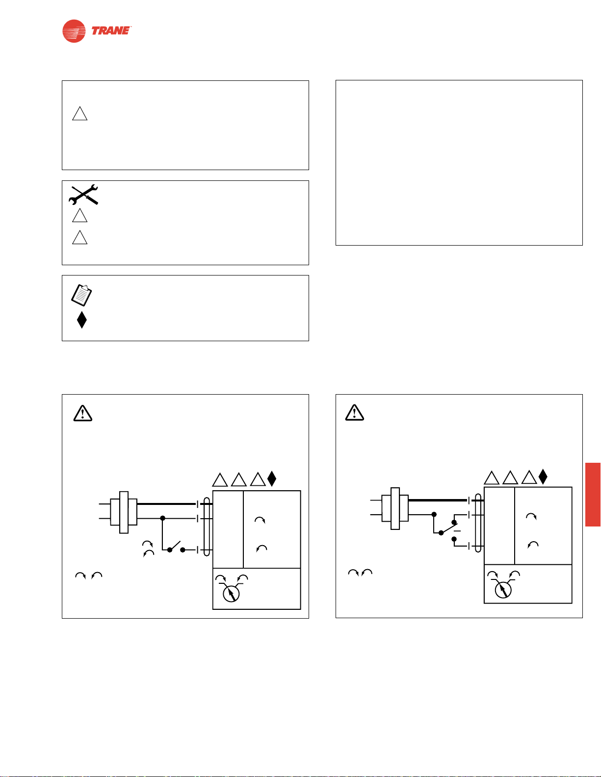
Wiring Diagrams
95
I20683 - Subject to change.
TLMB
TLMB24-3 (-T)
On/Off-Floating Point Control, Non-Spring Return, Direct Coupled, 24 V
TLMB24-3 - Typical Specification:
Floating point, on/off control damper actuators shall be
electronic direct-coupled type, which require no crankarm
and linkage and be capable of direct mounting to a shaft
from 1/4” to 5/8”. Shafts up to 3/4” diameter can be
accommodate with an accessory clamp. Actuators shall
have brushless DC motor technology and be protected
from overload at all angles of rotation. Actuators shall have
reversing switch and manual override on the cover. If
required, actuator will be provided with screw terminal strip
for electrical connections (TLMB24-3-T). Run time shall be
constant and independent of torque. Actuators are cULus
listed, and be manufactured under ISO 9001 International
Quality Control Standards. Actuators shall be as
manufactured by Belimo.
W500
W501
On/Off
Floating point or On/Off control
CAUTION
2
Equipment damage!
Up to 4 actuators may be connected in parallel.
With 4 actuators wired to one 500Ω resistor.
Power consumption must be observed and input
impedance must be observed.
Meets cULus or UL and CSA requirements without
the need of an electrical ground connection.
3
5
Actuator may also be powered by 24 VDC.
Actuators with plenum rated cable do not have
numbers on wires; use color codes instead.
Actuators with appliance cables use numbers.
INSTALLATION NOTES
APPLICATION NOTES
WARNING
Live Electrical Components!
During installation, testing, servicing and troubleshooting of this product, it maybe
necessary to work with live electrical components. Have a qualified licensed electrician
or other individual who has been properly trained in handling live electrical components
perform these tasks. Failure to follow all electrical safety precautions when exposed
to live electrical components could result in death or serious injury.
24 VAC Transformer
Line
Volts
a open
a closed
The indication of direction
is valid for switch position 1.
5
3
2
Blk (1) Common
Red (2) +
a
Wht (3) +
1 0
–
TLMB24-3
WARNING
Live Electrical Components!
During installation, testing, servicing and troubleshooting of this product, it maybe
necessary to work with live electrical components. Have a qualified licensed electrician
or other individual who has been properly trained in handling live electrical components
perform these tasks. Failure to follow all electrical safety precautions when exposed
to live electrical components could result in death or serious injury.
5
24 VAC Transformer
Line
Volts
The indication of direction
is valid for switch position 1.
3
2
Blk (1) Common
Red (2) +
Wht (3) +
1 0
TLMB24-3
–
Page 96
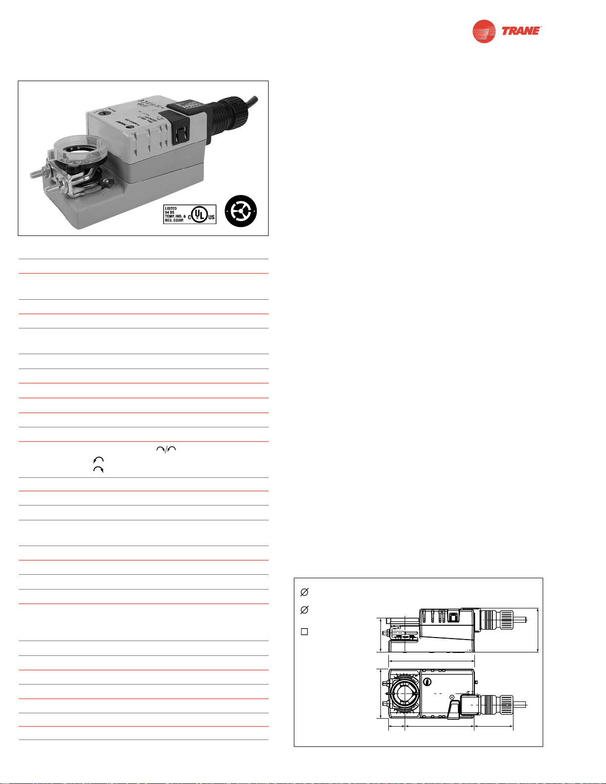
96
I20683 - Subject to change.
TLMB24-SR (-T)
Proportional Control, Non-Spring Return, Direct Coupled, 24V, for 2 to 10 VDC and 4 to 20 mA
Torque min. 45 in-lb for control of damper
surfaces up to 11 sq ft.
TLMB24-SR
TLMB24-SR-T
TLMB24-SR-T.1 (bulk)
Application
For proportional modulation of dampers in HVAC systems.
Actuator sizing should be done in accordance with the
damper manufacturer’s specifications.
The actuator is mounted directly to a damper shaft from
1/4” up to 5/8” in diameter by means of its universal clamp.
Shafts up to 3/4” diameter can be accommodated by an
accessory clamp.
The actuator operates in response to a 2 to 10 VDC, or with
the addition of a 500Ω resistor, a 4 to 20 mA control input
from an electronic controller or positioner. A 2 to 10 VDC
feedback signal is provided for position indication or
master-slave applications.
Operation
The actuator is not provided with and does not require any
limit switches, but is electronically protected against overload.
The anti-rotation strap supplied with the actuator will prevent
lateral movement.
The TLMB series provides 95° of rotation and a visual
indicator indicates position of the actuator. When reaching
the damper or actuator end position, the actuator
automatically stops. The gears can be manually disengaged
with a button on the actuator cover.
The TLMB24-SR… actuators use a sensorless brushless DC
motor, which is controlled by an Application Specific
Integrated Circuit (ASIC). The ASIC monitors and controls
the actuator’s rotation and provides a digital rotation sensing
(DRS) function to prevent damage to the actuator in a stall
condition. Power consumption is reduced in holding mode.
Add on auxiliary switches or feedback potentiometers are
easily fastened directly onto the actuator body for signaling
and switching functions
For all accessories, see pages 110 and 132.
Dimensions
(All numbers in brackets are in millimeters.)
D120
Technical Data TLMB24-SR
Power Supply 24 VAC ± 20% 50/60 Hz
24 VDC ± 10%
Power Consumption 1.5 W (0.4 W)
Transformer Sizing 3 VA (Class 2 power source)
Electrical Connection 3 ft, 18 GA plenum rated cable
1/2” conduit connector
Overload Protection electronic throughout 0° to 95° rotation
Operating Range Y 2 to 10 VDC, 4 to 20 mA
Input Impedance 100kΩ (0.1 mA), 500Ω
Feedback Output U 2 to 10 VDC (max 0.5 mA)
Angle of Rotation max. 95°, adjust. with mechanical stop
Torque 45 in-lb [5 Nm]
Direction of Rotation
reversible with switch. Actuator will move:
=CCW with decreasing control signal (10➞2V)
=CW with decreasing control signal (10➞2V)
Position Indication reflective visual Indicator (snap-on)
Manual Override external push button
Running Time 95 seconds, constant independent of load
Humidity 5 to 95% RH non condensing
(EN 60730-1)
Ambient Temperature -22°F to +122°F [-30°C to +50°C]
Storage Temperature -40°F to +176°F [-40°C to +80°C]
Housing NEMA 2/IP54
Housing Material UL94-5VA
Agency Listings cULus acc. to UL 60730-1/-2-14 and
CAN/CSA C22.2 No.24, CE according
to 73 / 23 / EEC
Noise Level <35dB(A)
Servicing maintenance free
Quality Standard ISO 9001
Weight 1.1 lbs [0.5 Kg]
TLMB24-SR-T
Electrical connection Screw terminal (for 26 to 14 GA wire)
Housing NEMA 1/IP20
O
M
L
©
O
A
H
B
r
r
o
u
t
s
o
h
M
l
e
s
C
s
D
1/4” to 5/8” [6 to 16]
5/8" Centered
1/4” to 3/4” [6 to 20]
with K-LM20 Accessory
5/8" Centered
5/16” to 9/16” [6 to 14]
1.85” [47]
2.6” [66]
0.86”
[22]
4.57” [116]
3.7” [94]
2.34” [59.4]
2” [50.8]
Page 97
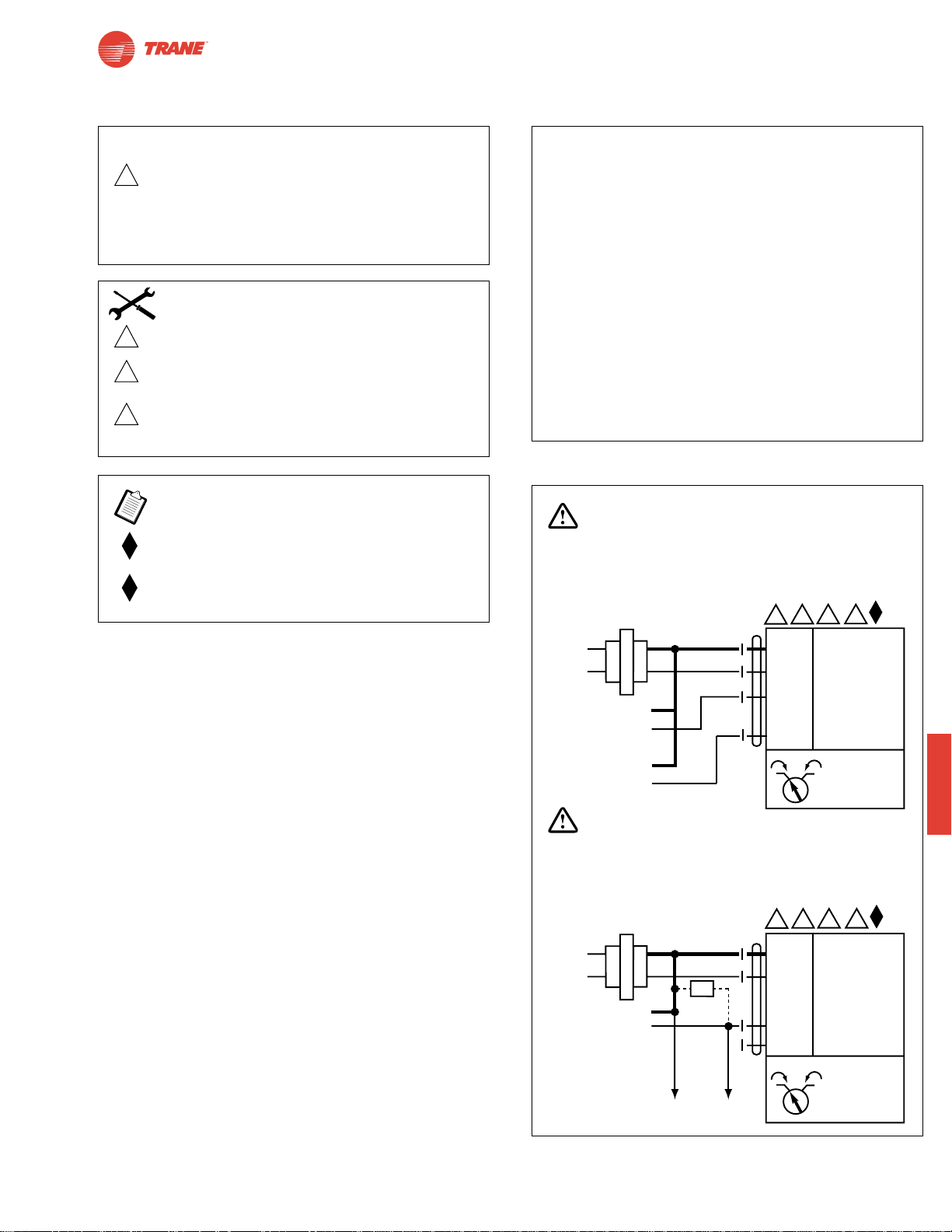
97
I20683 - Subject to change.
TLMB
Wiring Diagrams
TLMB24-SR… - Typical Specification:
Proportional control damper actuators shall be electronic
direct-coupled type, which require no crankarm and linkage
and be capable of direct mounting to a shaft from 1/4” to
5/8”. Shafts up to 3/4” diameter can be accommodate with
an accessory clamp. Actuators must provide proportional
damper control in response to a 2 to 10 VDC or, with the
addition of a 500Ω resistor, a 4 to 20 mA control input from
an electronic controller or positioner. Actuators shall have
brushless DC motor technology and be protected from
overload at all angles of rotation. Actuators shall have
reversing switch and manual override on the cover. If
required, actuator will be provided with screw terminal strip
for electrical connections (TLMB24-SR-T). Run time shall
be constant and independent of torque. A 2 to 10 VDC
feedback signal shall be provided for position indication.
Actuators are cULus listed, and be manufactured under
ISO 9001 International Quality Control Standards.
Actuators shall be as manufactured by Belimo.
TLMB24-SR (-T)
Proportional Control, Non-Spring Return, Direct Coupled, 24V, for 2 to 10 VDC and 4 to 20 mA
W502
2 to 10 VDC and 4 to 20 mA control of TLMB24-SR
2
Equipment damage!
Up to 4 actuators may be connected in parallel.
With 4 actuators wired to one 500Ω resistor.
Power consumption must be observed and input
impedance must be observed.
Meets cULus or UL and CSA requirements without
the need of an electrical ground connection.
The ZG-R01 500Ω resistor converts the 4 to 20 mA
control signal to 2 to 10 VDC.
3
5
6
Actuator may also be powered by 24 VDC.
Actuators with plenum rated cable do not have
numbers on wires; use color codes instead.
Actuators with appliance cables use numbers.
Only connect common to neg. (—) leg of control
circuits.
CAUTION
INSTALLATION NOTES
APPLICATION NOTES
WARNING
Live Electrical Components!
During installation, testing, servicing and troubleshooting of this product, it maybe
necessary to work with live electrical components. Have a qualified licensed electrician
or other individual who has been properly trained in handling live electrical components
perform these tasks. Failure to follow all electrical safety precautions when exposed
to live electrical components could result in death or serious injury.
24 VAC Transformer
2
5 6
3
Line
Volts
Control Signal
2 to 10 VDC
2 to 10 VDC
Feedback Signal
(–)
(+)
(–)
(+)
Blk (1) Common
Red (2) Hot +
Wht (3) Y Input, 2 to 10V
Org (5) U Output, 2 to 10V
1 0
–
TLMB24-SR
WARNING
Live Electrical Components!
During installation, testing, servicing and troubleshooting of this product, it maybe
necessary to work with live electrical components. Have a qualified licensed electrician
or other individual who has been properly trained in handling live electrical components
perform these tasks. Failure to follow all electrical safety precautions when exposed
to live electrical components could result in death or serious injury.
5 6
3
24 VAC Transformer
Line
Volts
2
Blk (1) Common
Red (2) Hot +
–
Ω
4 to 20 mA
Control Signal
(–)
(+)
500Ω
To other
actuators
Wht (3) Y Input, 2 to 10V
Org (5) U Output, 2 to 10V
1 0
TLMB24-SR
Page 98

98
I20683 - Subject to change.
Notes/Work Pad
Page 99

99
I20683 - Subject to change.
Installation and Operation
Non-Spring Return
General Information
If more torque is required than one TGMB can provide, TGMB24-SR may be installed on the same shaft.
Multiple Actuator Mounting
Preliminary Steps
1. Belimo actuators with NEMA 1 or NEMA 2 ratings should
be mounted indoors in a dry, relatively clean environment
free from corrosive fumes. If the actuator is mounted outdoors, a protective enclosure must be used to shield the
actuator.
2. For new construction work, order dampers with extended
shafts. Instruct the installing contractor to allow space for
mounting the Belimo actuator on the shaft.
For replacement of existing gear train actuators, there are two
options:
A. From a performance standpoint, it is best to mount the
actuator directly onto the damper shaft.
B. If the damper shaft is not accessible, mount the non-
spring return actuator with a ZG-NMA or ZG-GMA
crankarm kit, and a mounting bracket (ZG-100, ZG101, ZG-103, ZG-104)
Determining Torque Loading and Actuator Sizing
Damper torque loadings, used in selecting the correct size actuator, should be provided by the damper manufacturer.
If this information is not available, the following general selection guidelines can be used.
Damper Type Torque Loading
Opposed blade, without edge seals, for non-tight close-off applications 3 in-lb/sq. ft.
Parallel blade, without edge seals, for non-tight close-off applications 4 in-lb/sq. ft.
Opposed blade, with edge seals, for tight close-off applications 5 in-lb/sq. ft.
Parallel blade, with edge seals, for tight close-off applications 7 in-lb/sq. ft.
The above torque loadings will work for most applications under 2 in. w.g. static pressure or 1000 FPM face velocity.
For applications between this criteria and 3 in. w.g. or 2500 FPM, the torque loading should be increased by a multiplier
of 1.5. If the application calls for higher criteria up to 4 in. w.g. or 3000 FPM, use a multiplier of 2.0.
Table of Contents Page
General Mounting
❑ Standard ............................................100
❑ Reversible Clamp ..............................101
❑ Retrofit Brackets ................................102
Operation
❑ Electrical ............................................103
❑ Mechanical..........................................104
Wiring
❑ General ..............................................105
❑ Accessories ........................................106
Startup and Checkout..................................109
Page 100
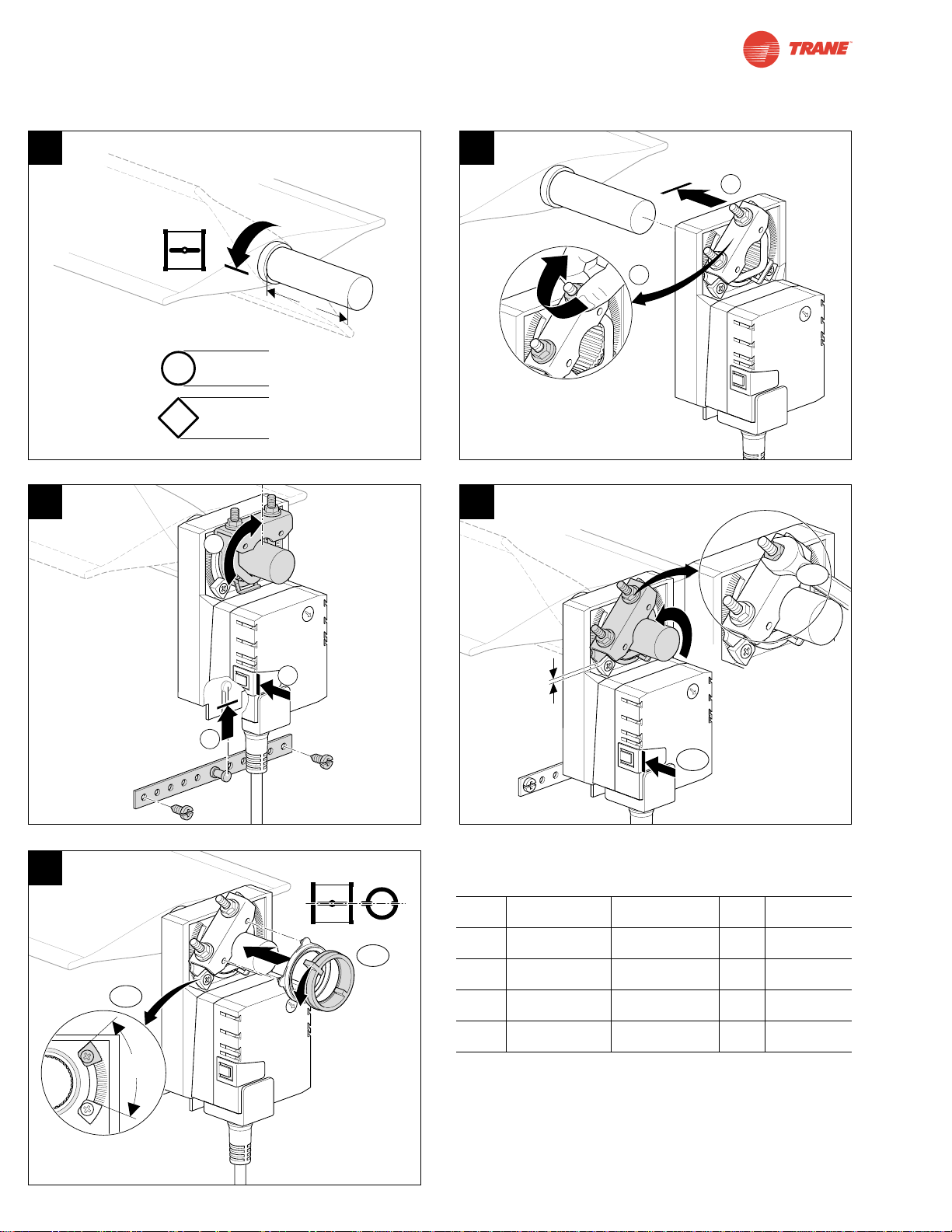
100
I20683 - Subject to change.
65°
See next page for Standard Mounting Instructions.
A* B C** D
TLMB 1/4” to 3/4” 5/16” to 3/4” 1.5” 4 to 5 ft-lb
TNMB 5/16” to 1.05” 2/5” to 1.05” 1.5” 6 to 7 ft-lb
TAMB 5/16” to 1.05” 2/5” to 1.05” 1.5” 6 to 7 ft-lb
TGMB 5/16” to 1.05” 2/5” to 1.05” 1.5” 6 to 7 ft-lb
*TLMB standard clamp has max 5/8” diameter. Accessory
clamp K-LM20 can be mounted for sizes up to 3/4” diameter.
TNMB and TAMB clamps have an insert that self-centers on
the following diameter shafts: 1/2” (default), 3/4” and 1.05”.
**Shorter with reversible clamp for TNMB, TAMB, and TGMB
1 2
3
5
4
Installation Instructions
Quick-Mount Visual Instructions for Mechanical Installation
C
A
B
1
2
D
1
2
10
1
5°
2
1
1
2
 Loading...