

Page 1
Operation and setting T24-V42(-V02)LON+T24-MP
Controller operation
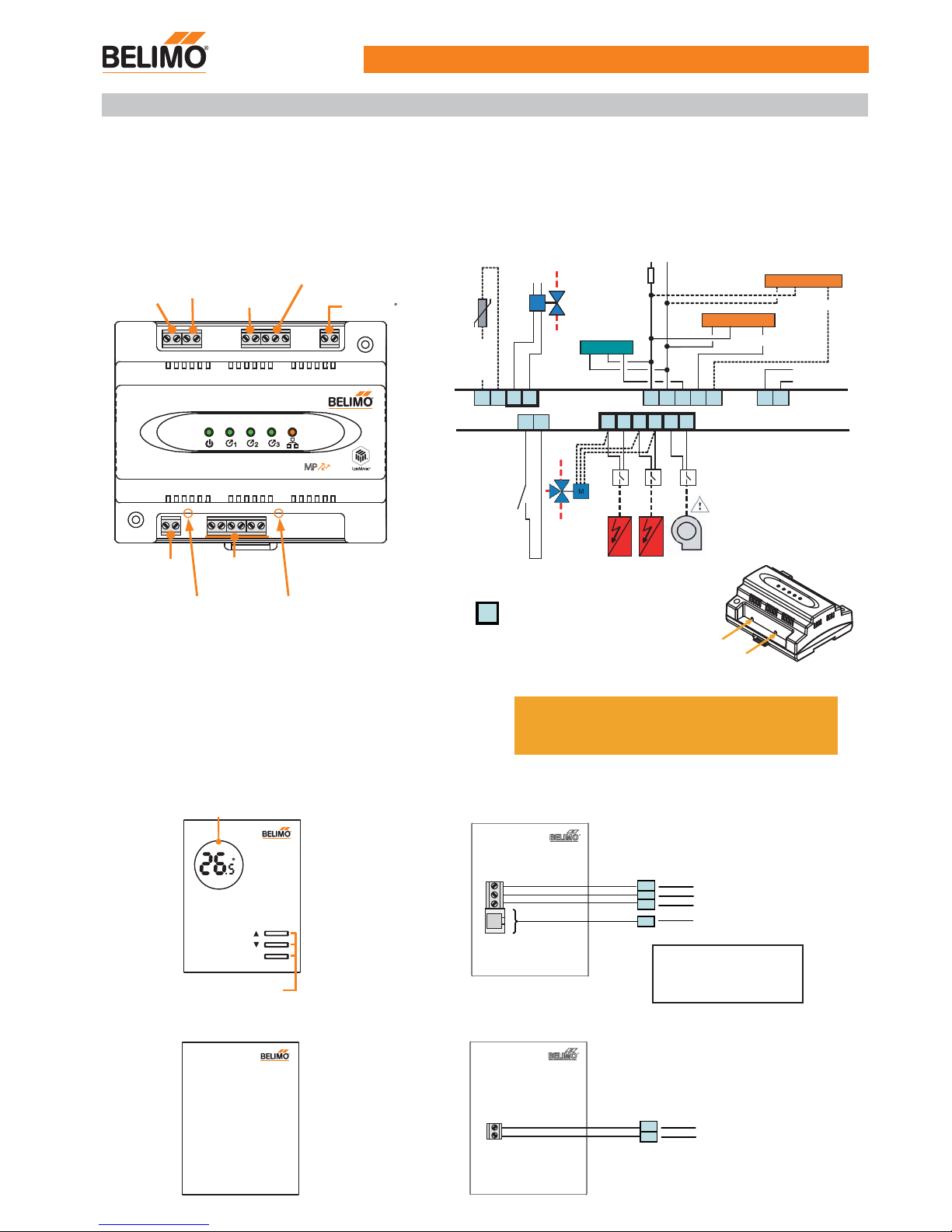
Functions of T24-V42(-V02)LON and wiring diagram
Functions of T24-MP and wiring diagram
1
The T24-V42(-V02)LON room control module offers the advantages of network control via the high performance LON transceiver.
This controller features screw terminal blocks, analogue input, digital input, analogue output, three 24Vac digital outputs, MP-Bus
interface for connection to the Belimo VAV Compact and optional T24-MP room unit or TG-R10000 room sensor. Suitable for new
or existing VAV system installations.
MP
BUS
®
External
sensor (AI)
NTC 10k
Analogue
output (AO)
2-10Vdc
AC 24V
Power
supply
MP-Bus (MP1~3)
LonWorks
Digital input
(DI)
Electrical heaters,
parallel/series fan
(3 x DO)
System
reset
LonWorks
service pin
1
2
3
DI Com
LON
B
24V
ac
LON
A
MP2MP1Com MP3
ComDO 1 DO3Co mDO2 Com
ComAI ComAO
1 2 3 5
1 2 3 5
1 2 5
T24- MP
T24-V42(-V02)LON
*Relay supplied
by others
Heater1Heater2Parallel
or
series fan
3-point
reheat
valve
24Vac
External
sensor
NTC 10k
VAV Compact
Occupa ncy
sensor
24Vac
~ З
LonWorks®
Caution: live voltage
*Power
supply
M
Modulating
reheat valve
VAV Compact
System
reset
LonWorks
service pin
Input & output assignment
Inputs
- AI External temp. sensor TG-R10000 *
- DI Remote setpoint shift, e.g. Occupancy sensor *
Open - Normal mode, Close - Economy mode
* Optional
Outputs
-
-
-
-
DO3 Parallel or series fan output 24Vac ON/OFF
DO2 Heating output II 24Vac ON/OFF
DO1 Heating output I 24Vac ON/OFF
AO Modulating reheat control 2...10Vdc
xxx
Not available for T24-V02LON
MODE
C
ON
Functional keys
LCD display
Functions of TG-R10000 and wiring diagram
RJ
12
Services tools connection
RJ 12
2
1
5
З
~
MP
24Vac
5
2
1
Room unit with LCD display and MMI functions
2
1
2
1
External sensor NTC 10k
Room sensor without MMI function
(TG-R10000)
1 A
1A fuse
Subject to technical change V1-27102008
Please note: A standard RJ12 6/4 (1:1)
cable can be plugged onto the RJ12 and
connected to a Belimo MP-Bus level
converter (e.g. ZTH-USB-MP) for the
Belimo PC-Tool.
Page 2
T24-V42(-V02)LON+T24-MP Operation and setting
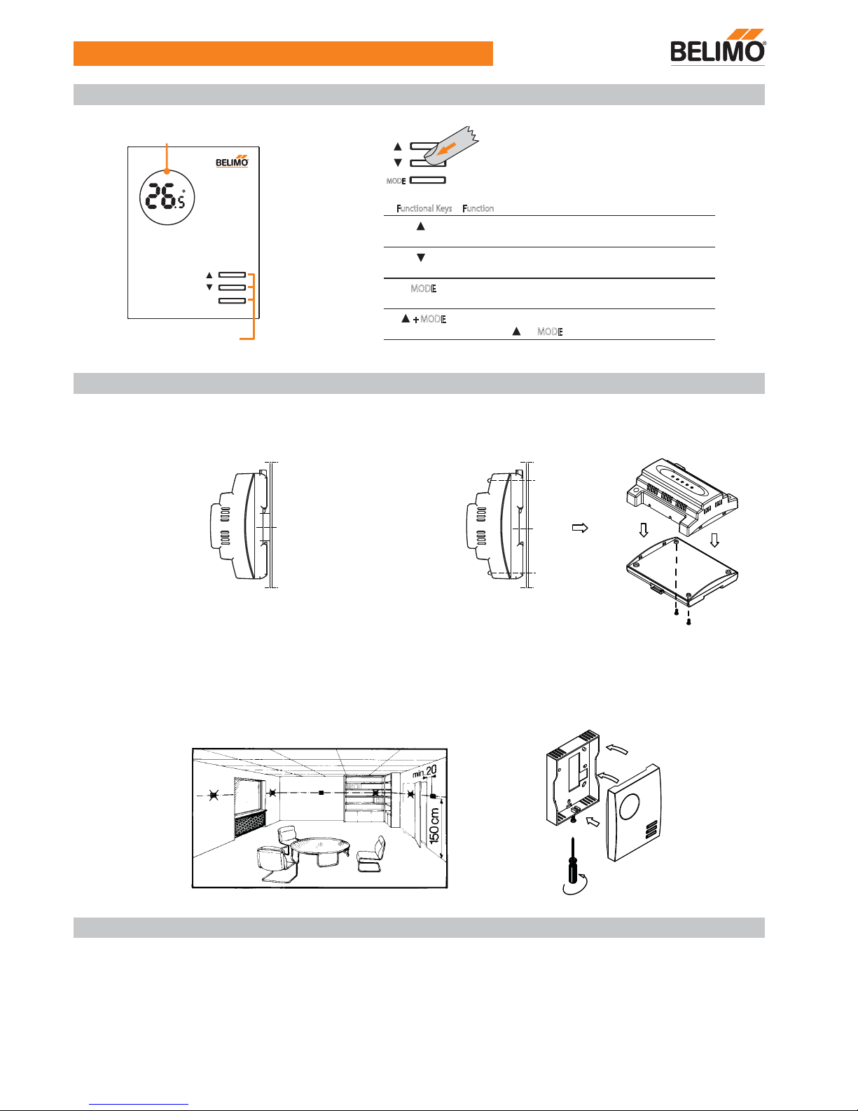
Principle of the functional keys of T24-MP
2
Mounting Notes
MODE
MODE
Functional Keys Function
+ MODE
Switch from “Normal mode” to “ Commissioning mode”
by pressing “ ”+ “ MODE
” for 5 seconds
Normal mode: Increment the temperature setpoint value
Commissioning mode: Adjust options of parameters.
Normal mode: Decrement the temperature setpoint value
Commissioning mode: Adjust options of parameters.
Standby mode or Normal mode selection.
Commissioning mode: Change parameters.
There are three functional keys on the cover of T24-MP,
the function of the buttons are listed as below.
MODE
C
ON
Functional keys
LCD display
The T24-V42(-V02)LON control module can be mounted as follows:
Observe all local installation and mounting regulations.
Wall mounted with 2 screws
DIN rail (EN 50 022-35 x 7.5) at least 120 mm long
The T24-MP or TG-R10000 room unit can be mounted as follows:
Wall mounted. Not in niches or bookshelves, not behind curtains, above or near heat sources and exposed to direct solar
radiation. Mounting height is about 1.5 m above the floor. The connecting wires can be run to the controller from a recessed
conduit box.
The room control module is designed for AC 24 V operating voltage.
However, when mounting in an environment greatly exposed to EMI, use only shielded cables.
- The low voltage must comply with the requirements for safety extra-low voltage (SELV) as per EN 60730.
- Use safety insulating transformers with double insulation as per EN 60742; they must be designed for 100 % on-time.
- Supplying voltages above AC 24 V to low voltage connections may damage or destroy the control module.
- Wiring terminal: Fixed screw terminals, 0.5...1.5 mm .
Electrical Installation
2
Page 3
T24-V42(-V02)LON+T24-MP Operation and setting
Standby
mode
Normal
mode
Commissioning
mode
Override
mode
Parameter setpoint
Temperature setpoint
Temperature display
......
......
Normal mode
Actual room temperature display
Factory setting of setpoint is 24ºC
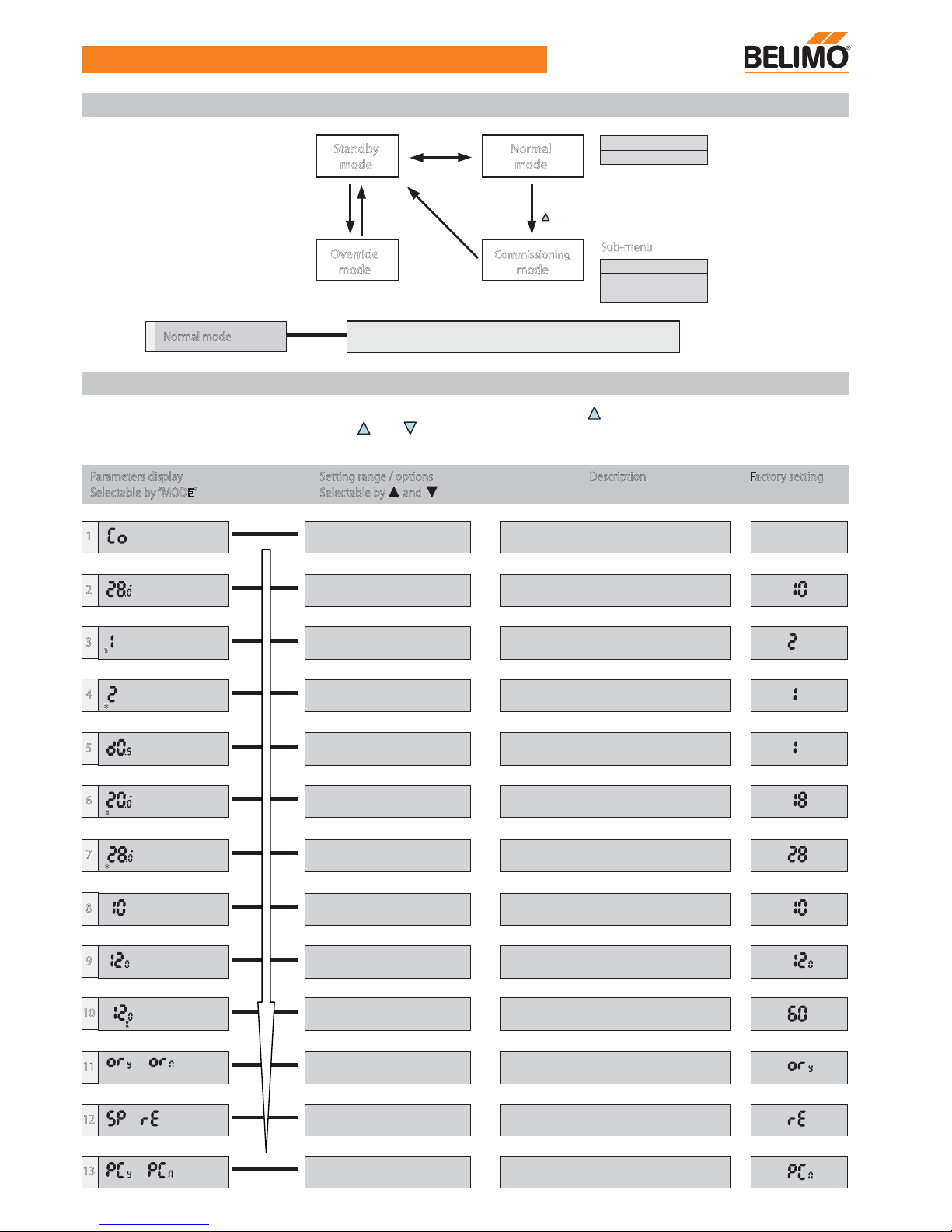
Controller operation menu
Sub-menu
Device start after power ON
Start-up
3
Menu structure
Parameters display Setting range / options
Selectable by andSelectable by “MODE”
Description Factory setting
1
Start to commissioning mode
(All input/output signals will switch off)
2
Minimum setpoint limitation in
Normal mode
10.0...30.0 (ºC), step 0.5
C
Eco
3
P-band in heating mode1...3 (K), step 1
4
P-band in cooling mode
5
Deadband range0.5, 1.0, 2.0 (K)
6
Setpoint of heating in Economy mode10.0...20.0 (ºC), step 0.5
1...3 (K), step 1
C
Eco
7
Setpoint of cooling in Economy mode
8
Application number selection10, 20, 30, 40, 50, 60, 21, 31,
41, 61, 12, 22, 32, 42, 52, 62.
9
Integral action time60...300 (sec), step 30
10
3 point floating control for reheat valve
11
Enable / Disable override by BMS
12
Only setpoint / room temp. & setpoint
display
60...150 (sec), step 10
C
Eco
ON
13
* Parameter or flow rates re-set by external
tool (PC-Tool)
or
or
or
Appl.
Int T
20.0...30.0 (ºC), step 0.5
Parameter setting
It is possible to set different parameter values in Commissioning Mode by pressing “ ” and “ MODE ” for 5s continuously.
Parameter values can be changed with the “ ” or “ ” buttons and confirm changes with the “ MODE ” button. After
completing the parameter setup, the system will return to Standby Mode and will keep storage in memory.
Press
“ ” & “ MODE ” 5 sec.
Press “ MODE ”
2 sec.
Time
out
Press
“ MODE ”
Press
“ MODE ”
Page 4
T24-V42(-V02)LON+T24-MP Operation and setting
MP-Bus - VAV Compact addresses
The MP-Bus is the Belimo master/salve bus. Up to 8 salves can be connected to an MP-master devices. Each MP salve must be assigned a unique
MP address between MP1 to MP8 before it can be operated on the
MP-Bus. Belimo VAV Compacts are set to PP (point-to-point) addressing
on delivery. PP is the required conventional control setting for CAV/VAV
functions with 0...10 / 2...10 V signals.
For T24-V42(-V02)LON control module, it can manage up to 3 MP devices
(MP1 to MP3). MP1 is for T24-MP, MP2 and 3 are for VAV-Compacts
connection, MP4 to 8 no useful at this stage.
T24-V42(-V02)LON, MP-Bus requirement
VAV Compacts can be pre-addressed with the PC-Tool (address / deaddress device). Pre-addressed VAV Compacts are automatically detected
and read as soon as they are connected to the T24-V42(-V02)LON.
Pre-addressing with Belimo PC-Tool V3.1
Room Unit - T24-MP;
It is default as MP1, no need to address with PC-Tool
When 1 VAV Compact connected with T24-V42(-V02)LON;
Pre-address it to MP2 or MP3 with Belimo PC-Tool
When 2 VAV Compacts connected with T24-V42(-V02)LON;
Pre-address it first actuator to MP2 and second actuator to MP3 with
Belimo PC-tool
Address setting
a) On the Room Unit - T24-MP
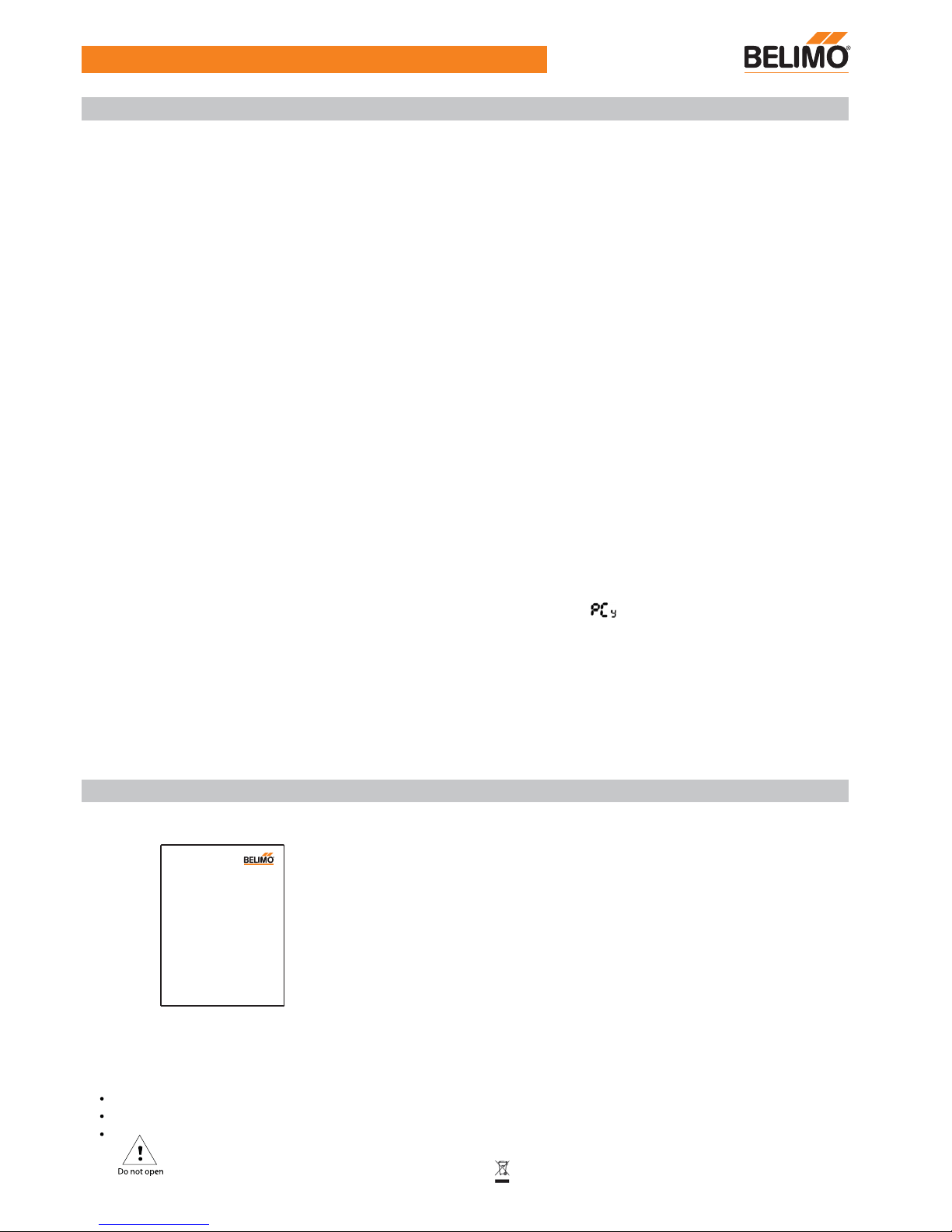
From the room unit enable ( ), the LCD will display "PS" and
have 30 minus allowable to entry into parameter setting mode by
using PC-Tool software. MP2 and MP3 can read together.
b) On the VAV-Compact
If the PC-Tool is connected locally to the service socket of the
VAV-Compact, it can be used to set this MP device. No other MP
devices can be accessed.
PC-Tool connection
Principle of the TG-R10000
Surface mounting TG-R10000 external sensor directly connect to T24-V42
(-V02)LON room module of analoge input (AI) point. This device without
MMI and LCD display. The temperature reading can though Building
Management System (BMS) by LONWork.
The device would not function if T24-MP is connected together.
4
The product would not perform normally under mains power fluctuations, or under strong electric fast transient/burst environment
Not to be exposed to dripping or splashing. The unit much be mounted on clean, dry indoor places
To be opened by accredited servicing agents only
Electronic control - Type 2.B action (micro-disconnection operation)
Separate collection for electrical and electronic equipment
 Loading...