

Page 1
E
F
P6400SU-317-250 Technical Data Sheet
Application
Water-side control of heating and cooling systems for AHUs and water coils.
Equal Percentage/ Linear: heating and cooling applications.
Operation
The Electronic Pressure Independent Control Valve is a two-way valve that
maintains constant flow regardless of pressure variations in the system.
Product Features
Provides constant flow regardless of pressure variations in the system.
Maximizes chiller Delta T, preventing energizing additional chillers due to low
Delta T. Simplified valve sizing and selection, no Cv calculations required.
Technical Data
Fluid chilled or hot water, up to 60% glycol max
Flow characteristic equal percentage or linear
Valve Size [mm] 4” [100]
Pipe connector pattern to mate with ANSI 250 flange
Housing Cast iron - GG 25
Flow measuring pipe Ductile cast iron - GGG50
Ball stainless steel
Stem stainless steel
Stem seal EPDM (lubricated)
Seat PTFE
O-ring Viton
Characterized disc stainless steel
Package EPDM
Body Pressure Rating ANSI Class 250, standard class B
ANSI Class 250
Number of Bolt Holes 8
Differential Pressure Range 5...50 psi or 1...50 psi see flow reductions
Close-off pressure ∆ps 310 psi
Ambient temperature -22...122°F [-30...50°C]
Inlet Length to Meet Specified
Measurement Accuracy
Ambient humidity max. 95% r.H., non-condensing
Measuring accuracy flow ±2%*
Control accuracy ±5%
Flow Measurement Repeatability ±0.5%
Sensor Technology ultrasonic with glycol and temperature
Rangeability Sv 100:1
Power supply for the flow sensor sensor is powered by the actuator
Weight 137.6 lb [63 kg]
Date created, 06/18/2020 - Subject to change. © Belimo Aircontrols (USA), Inc.
GPM 317
Fluid Temp Range (water) 14...250°F [-10...120°C]
Leakage rate 0%
*All flow tolerances are at 68°F (20°C) & water.
(open loop/steam not allowed)
chart in tech doc
5X nominal pipe size (NPS)
compensation
333500
P6400SU-317-250 GRB(X) GKRB(X)
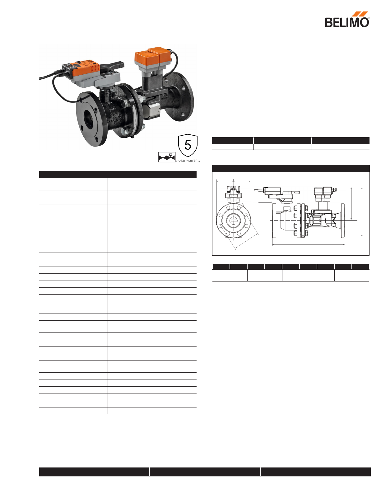
Dimensions (Inches [mm])
I
G
A B C D E F G H1 I
18.7” [474] 13.1”
[333]
Non-Spring Electronic fail-safe
H1
A, B
8.1”
[206]
5.0” [127] 7.9”
[200]
3.1”
[80]
Suitable Actuators
D
C
0.9”
[22]
800-543-9038 USA 866-805-7089 CANADA 203-791-8396 LATIN AMERICA / CARIBBEAN
Page 2
GRX24-EP2 Technical Data Sheet
Technical Data
314522
Power Supply 24 VAC, ±20%, 50/60 Hz, 24 VDC, -10% /
+20%
Power consumption in operation 9.5 W
Transformer sizing 13 VA (class 2 power source)
Electrical Connection 18 GA plenum cable, 3 ft [1 m], with 1/2”
conduit connector
Overload Protection electronic thoughout 0...90° rotation
Operating Range 2...10 V (default), 4...20 mA w/ ZG-R01 (500
Ω, 1/4 W resistor), VDC variable
Input Impedance 100 kΩ (0.1 mA), 500 Ω
Position Feedback default 2...10 V, VDC variable
Angle of rotation 90°
Torque motor 360 in-lb [40 Nm]
Direction of motion motor reversible with pc tool
Position indication Mechanically, pluggable
Manual override external push button
Running Time (Motor) 90 s
Ambient humidity max. 95% r.H., non-condensing
Ambient temperature -22...122°F [-30...50°C]
Storage temperature -40...176°F [-40...80°C]
Degree of Protection IP54, NEMA 2, UL Enclosure Type 2
Housing material UL94-5VA
Agency Listing cULus acc. to UL60730-1A/-2-14, CAN/CSA
E60730-1:02, CE acc. to 2014/30/EU and
2014/35/EU
Noise level, motor 45 dB(A)
Servicing maintenance-free
Quality Standard ISO 9001
Weight 4.85 lb [2.2 kg]
†Rated Impulse Voltage 800V, Type action 1.B, Control Pollution Degree 3.
†Rated Impulse Voltage 800V, Type of action 1.AA, Control Pollution Degree 3
Date created, 06/18/2020 - Subject to change. © Belimo Aircontrols (USA), Inc.
800-543-9038 USA 866-805-7089 CANADA 203-791-8396 LATIN AMERICA / CARIBBEAN
Page 3
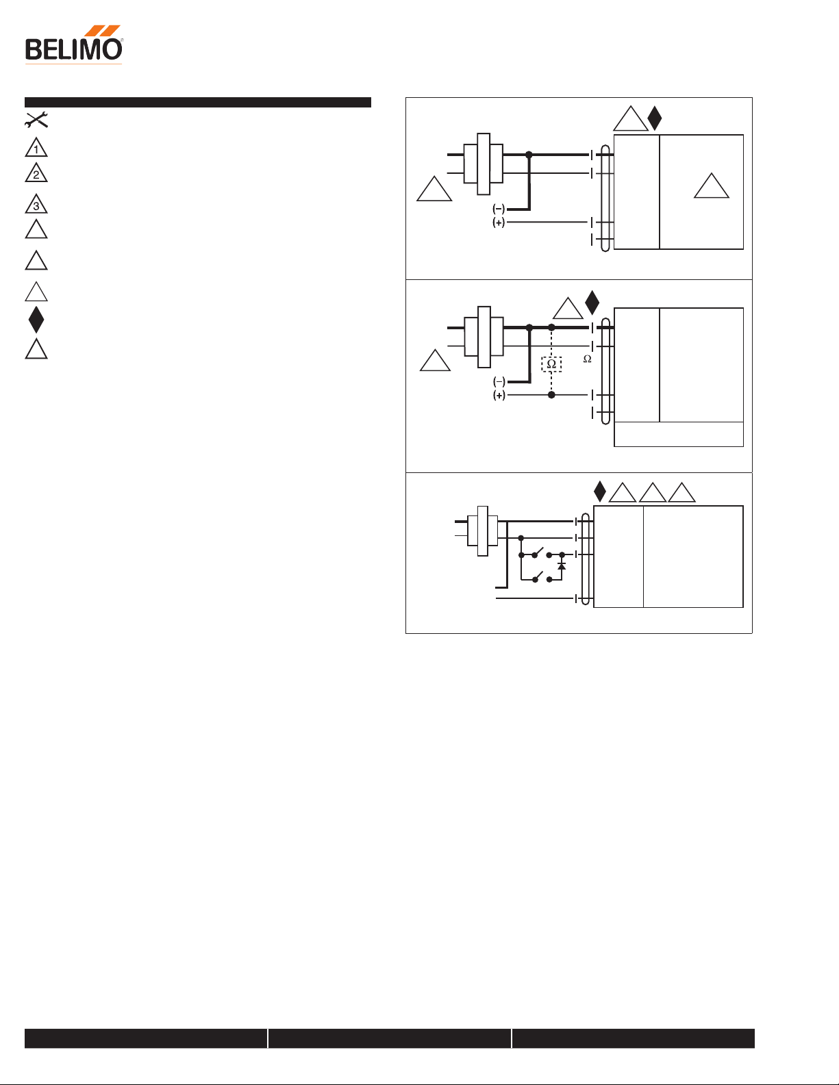
Wiring Diagrams
21
Line
V
Line
V
24 VAC Transformer
Contr
Feedback VDC
INSTALLATION NOTES
Provide overload protection and disconnect as required.
Actuators may be connected in parallel. Power consumption and input
impedance must be observed.
Actuators may also be powered by 24 VDC.
Actuators are provided with color coded wires. Wire numbers are
4
provided for reference.
Actuators are provided with a numbered screw terminal strip instead of
16
a cable.
IN4004 or IN4007 diode required
Meets cULus requirements without the need of an electrical ground
connection.
WARNING! LIVE ELECTRICAL COMPONENTS!
!
During installation, testing, servicing and troubleshooting of this
product, it may be necessary to work with live electrical components.
Have a qualified licensed electrician or other individual who has been
properly trained in handling live electrical components perform these
tasks. Failure to follow all electrical safety precautions when exposed to
live electrical components could result in death or serious injury.
GRX24-EP2 Technical Data Sheet
24 VAC/DC Transformer
olts
3
Control Signal
2 to 10 VDC
2 to 10 VDC Flow Feedback Signal (+)
24 VAC/DC Transformer
2
olts
3
ol Signal
4 to 20 mA
or
2 to 10 VDC
500
1/4 W
2
Blk (1) Common
Red (2) + Hot
Wht (3)
Org (5)
Blk (1) Common
Red (2) + Hot
Wht (3)
Org (5)
Y Input 2 to 10 V
U Output 2 to 10 V
Y1 Input, 2 to 10 V
U Output, 2 to 10 V
...MFT
18
24 VAC Transformer
Line
Volts
(–)
Position
(+)
1 2
Blk (1) Common
Red (2) Hot +
Wht (3) Y Input
Org (5) U Output
21
Date created, 06/18/2020 - Subject to change. © Belimo Aircontrols (USA), Inc.
800-543-9038 USA 866-805-7089 CANADA 203-791-8396 LATIN AMERICA / CARIBBEAN
 Loading...