

Page 1

Belimo Pressure Independent
Control Valve Range
- EPIV
Technical Databook
Version 3.3
Belimo Asia Pacifi c
Page 2

Page 3
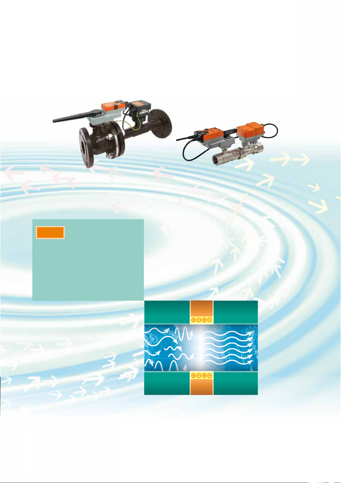
Electronic Pressure Independent
Control Valve
(EPIV)
EPIV – uses a flow
sensor and an electronic
controller instead of a
mechanic regulator to
allocate a defined flow
Page 4
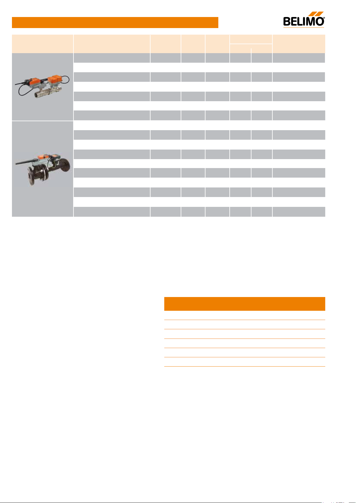
Product Overview
Electronic Pressure
Independent Valve EPIV
Model No.
Model No.
EP015R+MP
EP020R+MP
EP025R+MP
EP032R+MP
EP040R+MP
EP050R+MP
EP050R+MP-N
P6065W800E-MP
P6080W1100E-MP
P6100W2000E-MP
P6125W3100E-MP
P6150W4500E-MP
P6065W806E-MP
P6080W1106E-MP
P6100W2006E-MP
P6125W3106E-MP
P6150W4506E-MP
Frequency
[Hz]
50/60
50/60
50/60
50/60
50/60
50/60
50/60
50
50
50
50
50
60
60
60
60
60
DN
[mm]
15
20
25
32
40
50
50
65
80
100
125
150
65
80
100
125
150
Torque
[Nm]
5Nm
5Nm
5Nm
10Nm
10Nm
20Nm
20Nm
20Nm
20Nm
40Nm
40Nm
40Nm
20Nm
20Nm
40Nm
40Nm
40Nm
Nominal Flow
[l/s] [l/min]
0.35
0.65
1.15
1.8
2.5
4.8
6.3
8
11
20
31
45
8
11
20
31
45
21
39
69
108
150
288
378
480
660
1200
1860
2700
480
660
1200
1860
2700
Adjustable max.
fl ow rate [m³/h]
0.38…1.26
0.7…2.34
1.24…4.14
1.94…6.48
2.7…9
5.18…17.28
6.8...22.68
8.64…28.8
11.88...39.6
21.6…72
33.48…111.6
48.6…162
8.64…28.8
11.88...39.6
21.6…72
33.48…111.6
48.6…162
Note:
• The Electronic Pressure Independent Valve (EPIV) must be ordered together with the Rotary Actuator.
• Ordering example:
No part on EPIV can be ordered as a standard product.
• Electronic Fail-Safe Actuators are available for EPIV.
Contents
Product Overview 4
EPIV
EP..R+MP 5
P6..W..E-MP 7
Technical Data 9
Mounting Instructions 15
4
UL marked actuators is optional, please contact your local Sales Representative for details.
V3.3 07.2016•Subject to modifi cation
Page 5
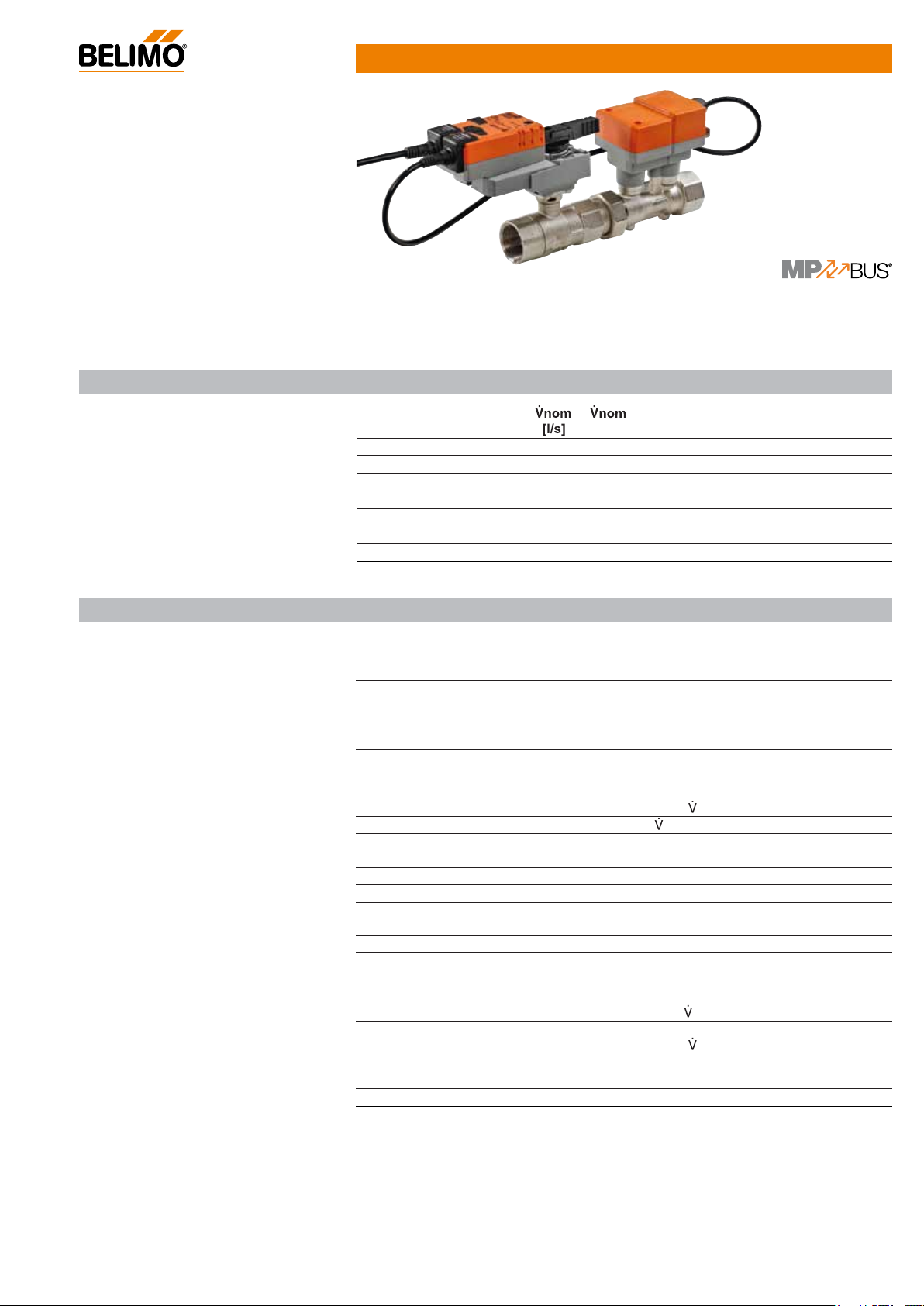
Characterised control valve (CCV) with
sensor-operated flow control, 2-way,
with internal thread
• Nominal voltage AC/DC 24V
• Control modulating
• For modulating water-side control
of air handling units and heating
systems
• Communication via Belimo MP-Bus
or conventional control
• Conversion of (active) sensor
signals and switching contacts
Type overview
Technical data sheet EP..R+MP
Technical data
Model No. Frequency
[Hz] [l/min]
EP015R+MP 50/60 0.35 21 2.9 15 1/2 25 3.2
EP020R+MP 50/60 0.65 39 4.9 20 3/4 25 3.2
EP025R+MP 50/60 1.15 69 8.6 25 1 25 3.2
EP032R+MP 50/60 1.8 108 14.2 32 1 1/4 25 3.2
EP040R+MP 50/60 2.5 150 21.3 40 1 1/2 25 3.2
EP050R+MP 50/60 4.8 288 32.0 50 2 25 3.2
EP050R+MP -N 50/60 6.3 378 32.0 50 2 25 3.2
*
: Theoretical kvs value for pressure drop calculation
Electrical data Nominal voltage AC/DC 24V
Nominal voltage frequency 50/60 Hz
Nominal voltage range AC 19.2...28.8V / DC 21.6...28.8V
Power consumption in operation 4.5 W
Power consumption in rest position 1.4 W
Power consumption for wire sizing 7
Connection supply / control Cable 1m, 4x 0.75mm²
Parallel operation Yes (note the performance data)
Flow measurement
Functional data
Measuring principle Ultrasonic volumetric flow measurement
Measuring accuracy ±2%
Min. flow measurement
Torque motor 5Nm (DN 15...25) / 10 Nm (DN 32 + 40) /
Positioning signal Y DC 0...10V
Operating range Y DC 2...10V
Operating range Y variable Start point DC 0.5...24V
Position feedback U DC 2...10V
Position feedback U variable Start point DC 0.5...8V
Sound power level motor max. 45
Adjustable flow rate Vmax
Control accuracy ±5%
Media Cold and hot water, water with glycol up to
Media temperature -10°C...120°C
kvs theor.*
[m³/h]
VA
(of 25...100%
0.5% of
20Nm (DN 50)
End point DC 8.5...32V
End point DC 2…10V
30...100% of
(of 25...100%
max. 60% vol.
nom
dB(A)
DN
[mm] Rp [”] PN [bar]
nom at 20°C, Glycol 0% vol. )
nom
nom at 20°C, Glycol 0% vol. )
n(gl)
[ ]
V3.3 07.2016•Subject to modifi cation
UL marked actuators is optional, please contact your local Sales Representative for details.
5
Page 6
EP..R+MP
Technical data
Characterised control valve (CCV) with sensor-operated flow control,
2-way, with internal thread
Safety notes
Functional data
Closing pressure
Differential pressure
ps
pmax
1380 kPa
350kPa
Flow characteristic Equal percentage (VDI/VDE 2178), linear
Leakage rate Air bubble-tight (Leakage rate A, EN12266-1)
Pipe connections Internal thread (ISO 7-1/ EN10226-1)
Installation position Upright to horizontal (in relation to the stem)
Maintenance
Maintenance-free
Manual override Gear disengagement with push-button, can be
locked
Running time 90s
Safety Protection class IEC/EN III Safety extra-low voltage
Degree of protection IEC/EN IP54
EMC CE according to 2004/108/EC
Mode of operation Type 1
Rated impulse voltage supply / control 0.8 kV
Control pollution degree 3
Ambient temperature -30...50°C
Non-operating temperature -40...80°C
Ambient humidity 95% r.h., non-condensing
Materials Housing Brass body, nickel-plated
Measuring pipe Brass body, nickel-plated
Ball Stainless steel AISI 316
Stem Stainless steel AISI 304
Stem seal O-ring EPDM
• The device has been designed for use in stationary heating, ventilation and air
conditioning systems and is not allowed to be used outside the specified field of
!
application, especially in aircraft or in any other airborne means of transport.
• Only authorised specialists may carry out installation. All applicable legal or institutional
installation regulations must be complied with during installation.
• The connection between the control valve and the measuring tube should not be
separated.
• The device contains electrical and electronic components and is not allowed to be
disposed of as household refuse. All locally valid regulations and requirements must be
observed.
Product features
Mode of operation
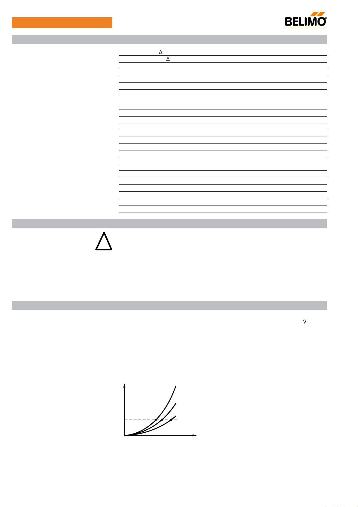
The actuator is comprised of three components: characterised control valve (CCV), measuring
pipe with volumetric flow sensor and the actuator itself. The adjusted maximum flow ( max) is
assigned to the maximum positioning signal (typically 10V/100%).
The actuator control can be either communicative or analogue. The medium is detected by the
sensor in the measuring pipe and is applied as the flow value. The measured value is balanced
with the setpoint. The actuator corrects the deviation by changing the valve position. The angle
of rotation α varies according to the differential pressure through the final controlling element
(see volumetric flow curves).
Flow rate curves
∆p1 < ∆p2 < ∆p
∆p
∆p
∆p
3
2
1
α
3
6
UL marked actuators is optional, please contact your local Sales Representative for details.
V3.3 07.2016•Subject to modifi cation
Page 7
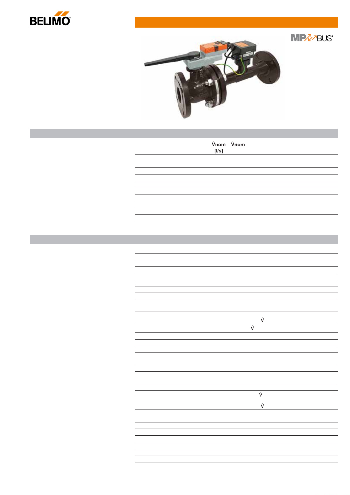
Characterised control valve (CCV) with
sensor-operated flow control, 2-way,
with flange PN16
• Nominal voltage AC/DC 24V
• Control modulating
• For modulating water-side control of
air handling unit and heating systems
• Communication via Belimo MP-Bus
or conventional control
• Conversion of (active) sensor signals
and switching contacts
Type overview
Technical data sheet P6..W..E-MP
Technical data
Model No. Frequency
[Hz] [l/min]
P6065W800E-MP 50
P6080W1100E-MP 50
P6100W2000E-MP 50
P6125W3100E-MP 50
P6150W4500E-MP 50
P6065W806E-MP 60
P6080W1106E-MP 60
P6100W2006E-MP 60
P6125W3106E-MP 60
P6150W4506E-MP 60
: Theoretical kvs value for pressure drop calculation*
Electrical data Nominal voltage AC/DC 24V
Nominal voltage frequency 50
Nominal voltage range AC 19.2...28.8V / DC 21.6...28.8V
Power consumption in operation 9.5 W
Power consumption in rest position 6.5 W
Power consumption for wire sizing 1
Connection supply / control Cable 1m, 4 x 0.75 mm²
Parallel operation Yes (note the performance data)
measurement Measuring principle Magnetic inductive volumetric flow
Flow
Measuring accuracy ±2%
Min. flow measurement
Functional data
Torque motor 20Nm (DN 65...80) / 40Nm (DN 100...150)
Positioning signal Y DC 0...10V
Operating range Y DC 2...10V
Operating range Y variable Start point DC 0.5...24V
Position feedback U DC 2...10V
Position feedback U variable Start point DC 0.5...8V
Sound power level motor max. 45
Adjustable flow rate max
Control accuracy ±5%
Media Cold and hot water, water with glycol up to max.
Media temperature -10°C...120°C
Closing pressure ∆ps 690 kPa
Differential pressure ∆pmax 340kPa
Flow characteristic Equal percentage (VDI/VDE 2178), linear
Leakage rate Air bubble-tight (Leakage rate A, EN12266-1)
Pipe connections Flange (ISO 7005-2 / EN 1092-1)
8 480 45 65 2 1/2 16 3.2
11 660 65 80 3 16 3.2
20 1200 115 100 4 16 3.2
31 1860 175 125 5 16 3.2
45 2700 270 150 6 16 3.2
8 480 45 65 2 1/2 16 3.2
11 660 65 80 3 16 3.2
20 1200 115 100 4 16 3.2
31 1860 175 125 5 16 3.2
45 2700 270 150 6 16 3.2
measurement
(of 25...100%
1.25% of
End point DC 8.5...32V
End point DC 2…10V
30...100% of
(of 25...100%
60% vol.
kvs theor.*
[m³/h]
/60Hz (upon request)
V A
3
nom at 20°C, Glycol 0% vol.)
nom
dB(A)
nom
nom at 20°C, Glycol 0% vol. )
[mm] Rp [”]
DN
PN
n(gl)
[bar]
[ ]
V3.3 07.2016•Subject to modifi cation
UL marked actuators is optional, please contact your local Sales Representative for details.
7
Page 8
P6..W..E-MP
!
α
Technical data
Safety notes
Characterised control valve (CCV) with sensor-operated flow
control, 2-way, with flange PN 16
Functional data Installation position Upright to horizontal (in relation to the stem)
Maintenance
Maintenance-free
Manual override Gear disengagement with push-button, can be
locked
Running time 90s
Safety Protection class IEC/EN
III Safety extra-low voltage
Degree of protection IEC/EN IP54
EMC CE according to 2004/108/EC
Mode of operation Type 1
Rated impulse voltage supply / control 0.8 kV
Control pollution degree 3
Ambient temperature -10...50°C
Non-operating temperature -20...80°C
Ambient humidity 95% r.h., non-condensing
Materials Housing EN-JL1040 (GG25 with protective paint)
Measuring pipe EN-GJS-500-7U (GGG50 with protective paint)
Ball Stainless steel AISI 316
Stem Stainless steel AISI 304
Stem seal EPDM Perox
• The device has been designed for use in stationary heating, ventilation and air conditioning
systems
and is not allowed to be used outside the specified field of application, especially
in aircraft or in any other airborne means of transport.
• Only authorised specialists may carry out installation. All applicable legal or institutional
installation regulations must be complied with during installation.
• The connection between the control valve and the measuring tube should not be separated.
• The device contains electrical and electronic components and is not allowed to be disposed of as
household refuse. All locally valid regulations and requirements must be observed.
Product features
Mode of operation The actuator is comprised of three components: characterised control valve (CCV),
Flow characteristic of the characterised
control valve
measuring pipe with volumetric flow sensor and the actuator itself. The adjusted maximum
max) is assigned to the maximum positioning signal (typically 10V).
flow (
The actuator control can be either communicative or analogue. The medium is detected
by the sensor in the measuring pipe and is applied as the flow value. The measured value
is balanced with the setpoint. The actuator corrects the deviation by changing the valve
position. The angle of rotation α varies according to the differential pressure through the
final controlling element (see volumetric flow curves).
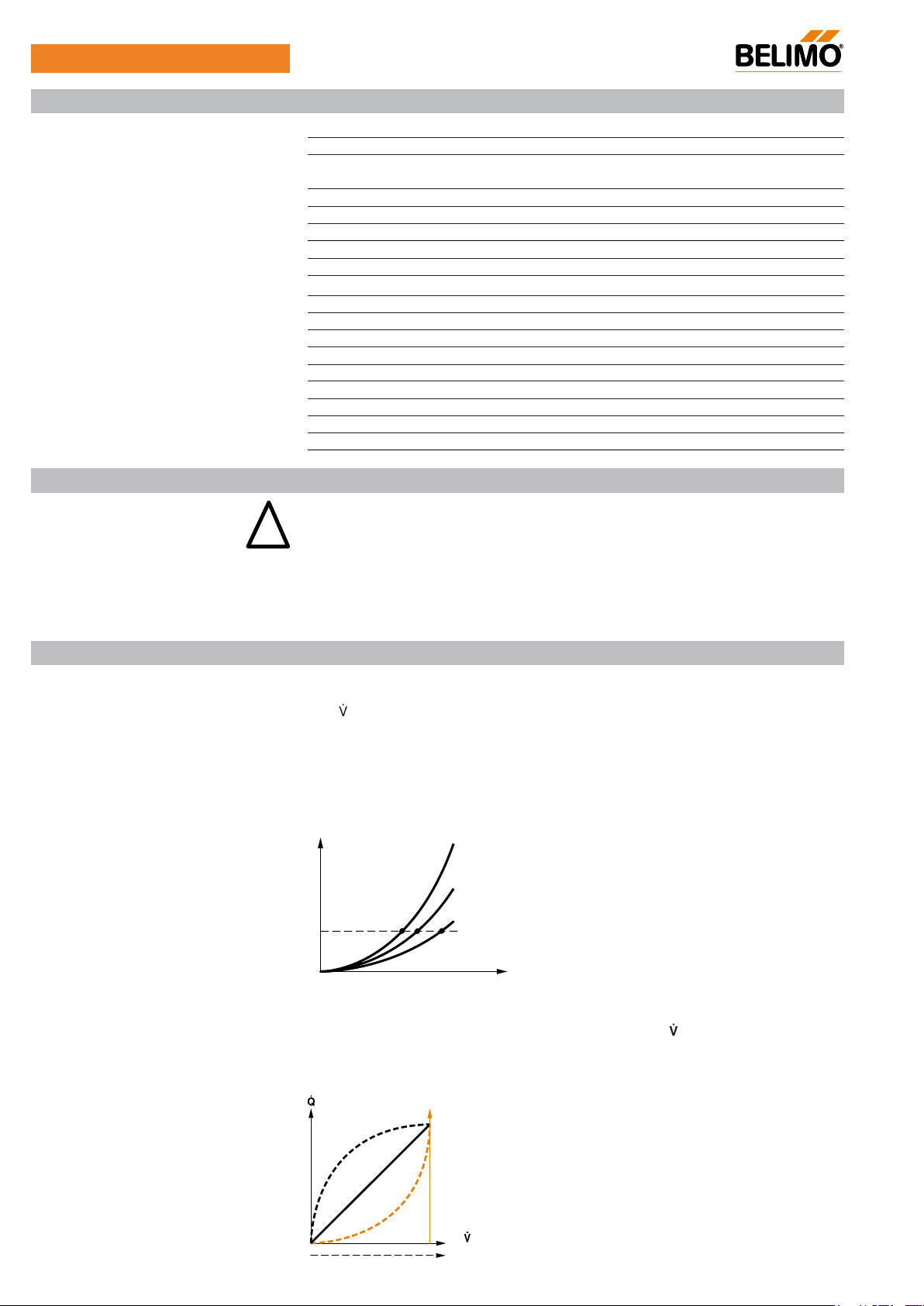
Flow rate curves
∆p
∆p
∆p
3
2
1
∆p1 < ∆p2 < ∆p
Heat exchanger transfer response
3
Depending on the construction, temperature spread, medium and hydraulic circuit, the
power Q is not proportional to the volumetric flow of the water
(curve 1). With the classical
type of temperature control, an attempt is made to maintain the control signal Y proportional
to the power Q (Curve 2) and is achieved by means of an equal-percentage valve
characteristic curve (Curve 3).
8
1
2
3
Y
UL marked actuators is optional, please contact your local Sales Representative for details.
V3.3 07.2016•Subject to modifi cation
Page 9
100%
100%
Y [V]
Product features
EP..R+MP / P6..W..E-MP
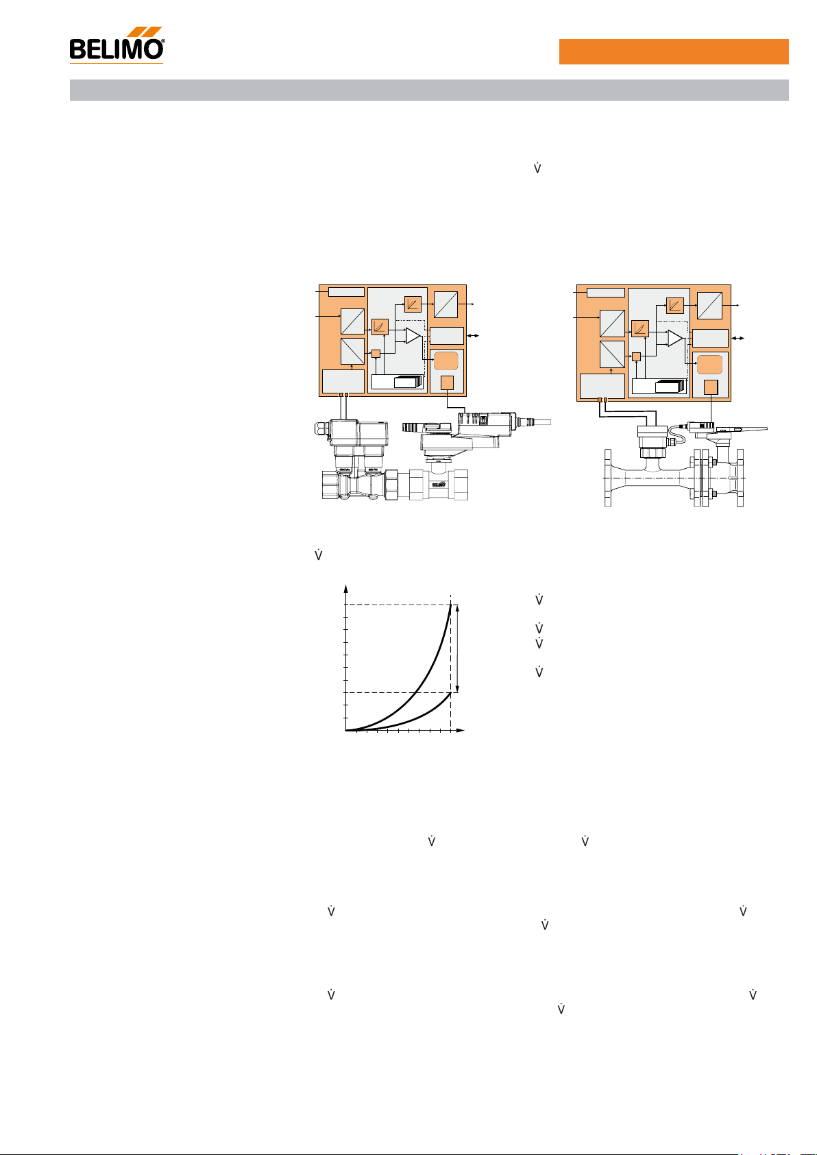
Control characteristics The velocity of the medium is measured in the measuring component (sensor electronics)
and converted to a flow rate signal.
The positioning signal Y corresponds to the power Q via the exchanger, the volumetric
flow is regulated in the EPIV. The control signal Y is converted into an equal-percentage
characteristic curve and provided with the .max value as the new reference variable w. The
momentary control deviation forms the positioning signal Y1 for the actuator.
The specially configured control parameters in connection with the precise flow rate sensor
ensure a stable quality of control. They are however not suitable for rapid control processes,
i.e. for domestic water control.
U5 displays the measured volumetric flow as voltage (factory setting). As an alternative, U5
can be used for displaying the valve opening angle.
Block diagram
D
U
Y
A
D
D
A
DN
1)
1)
w
Y
k
1
max
5
A
PP/MP
Y
A
1)
w
D
D
k
A
max
DN
M
D
U
1)
Y
1
5
A
PP/MP
M
Definitions
nom is the maximum possible flow.
[m3/h]
nom
max is the maximum flow rate which has been
set with the greatest positioning signal, e.g. 10V.
max can be set to between 30% and 100% of
nom.
min 0% (non-variable).
30%
0
max
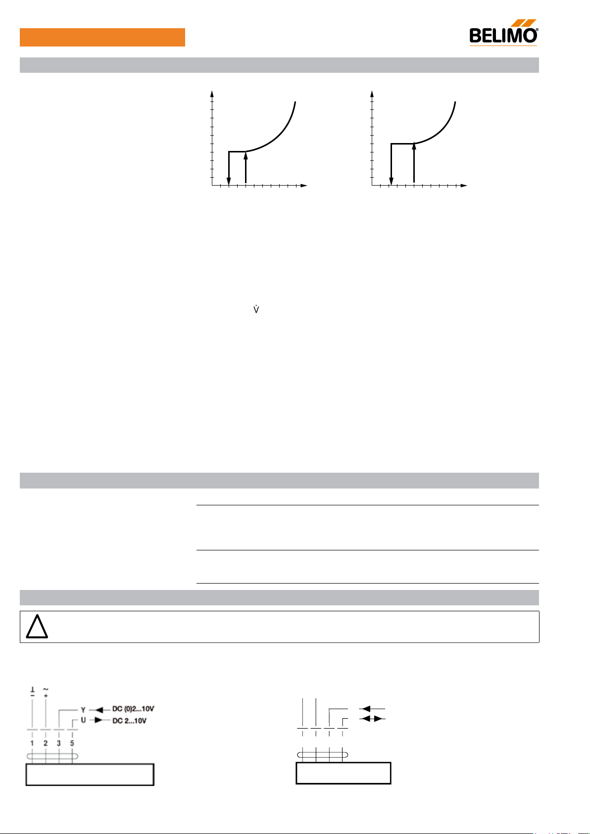
Creep flow suppression Given the very low flow speed in the opening point, this can no longer be measured by the
sensor within the required tolerance. This range is overridden electronically.
Opening valve
The valve remains closed until the volumetric flow required by the positioning signal Y
corresponds to 1% of
nom(DN15-DN50) / 2.5% of nom(DN65-DN150). The control along
the valve characteristic curve is active after this value has been exceeded.
Closing valve (DN15-DN50)
The control along the valve characteristic curve is active up to the required flow rate of 1%
of nom. Once the level falls below this value, the flow rate is maintained at 1% of nom. If
the level falls below the flow rate of 0.5% of nom required by the reference variable Y, then
the valve will close.
Closing valve (DN65-DN150)
The control along the valve characteristic curve is active up to the required flow rate of 2.5%
of nom. Once the level falls below this value, the flow rate is maintained at 2.5% of nom.
If the level falls below the flow rate of 1.25% of nom required by the reference variable Y,
then the valve will close.
V3.3 07.2016•Subject to modifi cation
UL marked actuators is optional, please contact your local Sales Representative for details.
9
Page 10
~
Sensor
2.5%
1.25%
2.5%
100%
Y [V]
1%
0.5%
1%
100%
Y [V]
!
EP..R+MP / P6..W..E-MP
Product features
Creep flow suppression
[m3/h]
[m3/h]
0
DN15-DN50
Converter for sensors Connection option for a sensor (active sensor or switching contact). The MP
0
DN65-DN150
actuator serves
as an analogue/digital converter for the transmission of the sensor signal via MP-Bus to the
higher level system.
Adjustable-parameter actuators The factory settings cover the most common applications. Individual parameters can be
altered with the Belimo service tool MFT-P or with the service tool ZTH AP.
Positioning signal inversion This can be inverted in cases of control with with an analogue positioning signal. The
inversion causes the reversal of the standard behaviour, i.e. at a positioning signal of 0%,
regulation is to
max or Qmax, and the valve is closed at a positioning signal of 100%.
Hydraulic balancing With the Belimo-Tools, the maximum flow rate (equivalent to 100% requirement) can
be adjusted on-site, simply and reliably, in a few steps. If the device is integrated in the
management system, then the balancing can be handled directly by the management
system.
Manual override Manual override with push-button possible - temporary, permanently. The gear is
disengaged and the actuator decoupled for as long as the button is pressed / latched.
High functional reliability The actuator is overload protected, requires no limit switches and automatically stops when
the end stop is reached.
Home position The actuator moves to the home position when the supply voltage is switched on for the first
time, i.e. at the time of commissioning or after pressing the "gear disengagement" key.
The actuator then moves into the required position in order to ensure the flow rate defined
by the positioning signal.
Accessories
Description Type
Electrical accessories Gateway MP to KNX/EIB, AC/DC 24 V, EIBA certified UK24EIB
Gateway MP for LonWorks®, AC/DC 24 V, LonMark-certified
Gateway MP to Modbus RTU, AC/DC 24 V
Gateway MP to BACnet MS/TP, AC/DC 24 V
Service Tools Service tool, for MF/MP/Modbus/LonWorks actuators and VAV
controller
Belimo PC-Tool, software for adjustments and diagnostics
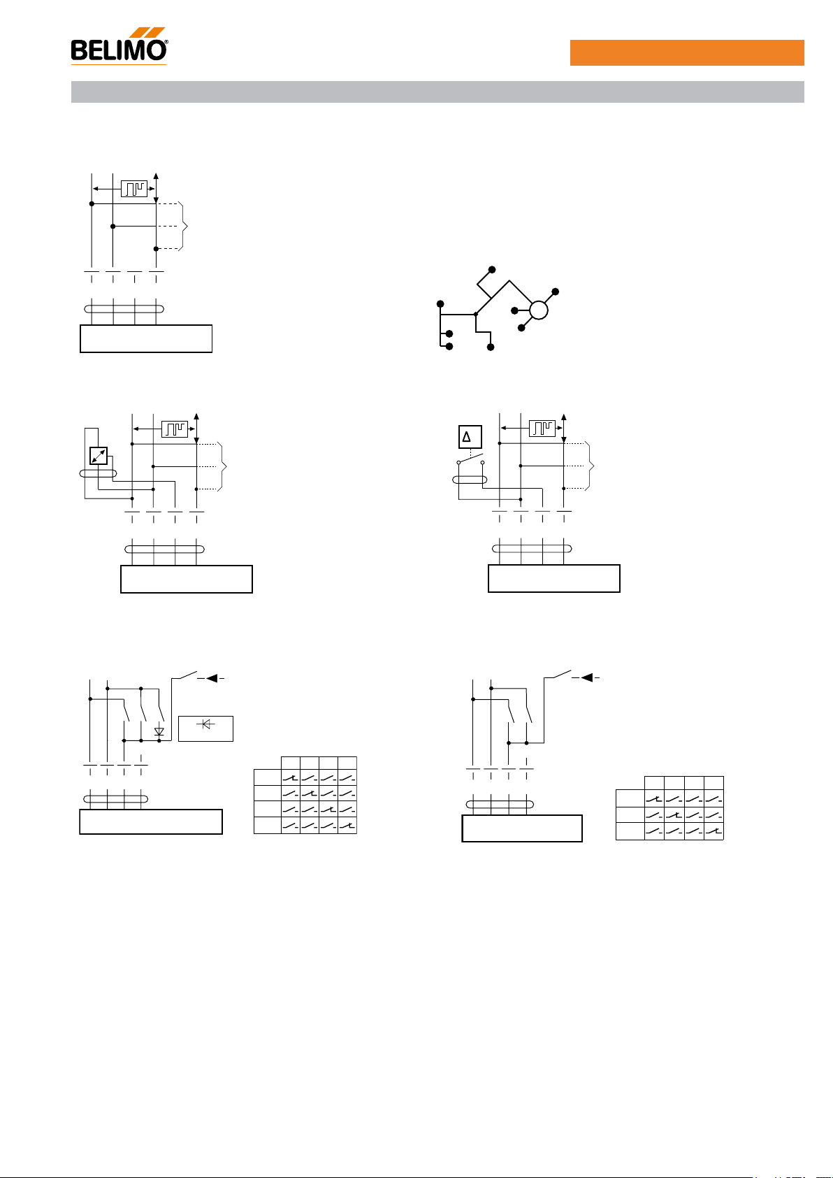
Electrical installation
Notes • Connection via safety isolating transformer.
• Parallel connection of other actuators possible. Note the performance data.
Wiring diagrams
AC/DC 24 V, modulating Operation on the MP-Bus
T
– +
Cable colours:
1 = black
2 = red
3 = white
5 = orange
1 32 5
Y
U
UK24LON
UK24MOD
UK24BAC
ZTH AP
MFT-P
MP
Cable colours:
1 = black
2 = red
3 = white
5 = orange
10
UL marked actuators is optional, please contact your local Sales Representative for details.
V3.3 07.2016•Subject to modifi cation
Page 11
~
T
~
de
+
de
-
~
T
~
T
EP..R+MP / P6..W..E-MP
Functions
Functions when operated on MP-Bus
Connection on the MP-Bus Power topology
MP
+
–
A)
There are no restrictions for the
1 2 3 5
U
Y
A) Additional actuators and
sensors (max. 8)
Connection of active sensors Connection of external switching contact
network topology (star, ring, tree
or mixed forms are permitted).
Supply and communication in the
same 3-wire cable
• no shielding or twisting required
• no terminating resister required
MP
+
–
A)
1 2 3 5
Y
U
A) Additional actuators and
sensors (max. 8)
• Supply AC / DC 24V
• Output signal DC 0 ... 10V
(max. DC 0 ... 32V)
• Resolution 30mV
Functions for actuators with specific parameters
Override control and limitation with AC 24 V with
relay contacts
T
T
a b d
5123
~
U
Y
e
e.g. 1N 4007
Y (DC 0 ... 10 V)
Close
max
Open
Y
ab
MP
+
–
p
A)
1 2 3 5
Y
U
A) Additional actuators and
sensors (max. 8)
• Switching current 16 mA @ 24V
• Start point of the operating
range must be parameterised on
the MP actuator as ≥ 0.6 V
Override control and limitation with DC 24 V with
relay contacts
Y (DC 0 ... 10 V)
ab
Close
max
Y
T
ab
~
Y
e
5123
U
V3.3 07.2016•Subject to modifi cation
UL marked actuators is optional, please contact your local Sales Representative for details.
11
Page 12
+
~
°9
EP..R+MP / P6..W..E-MP
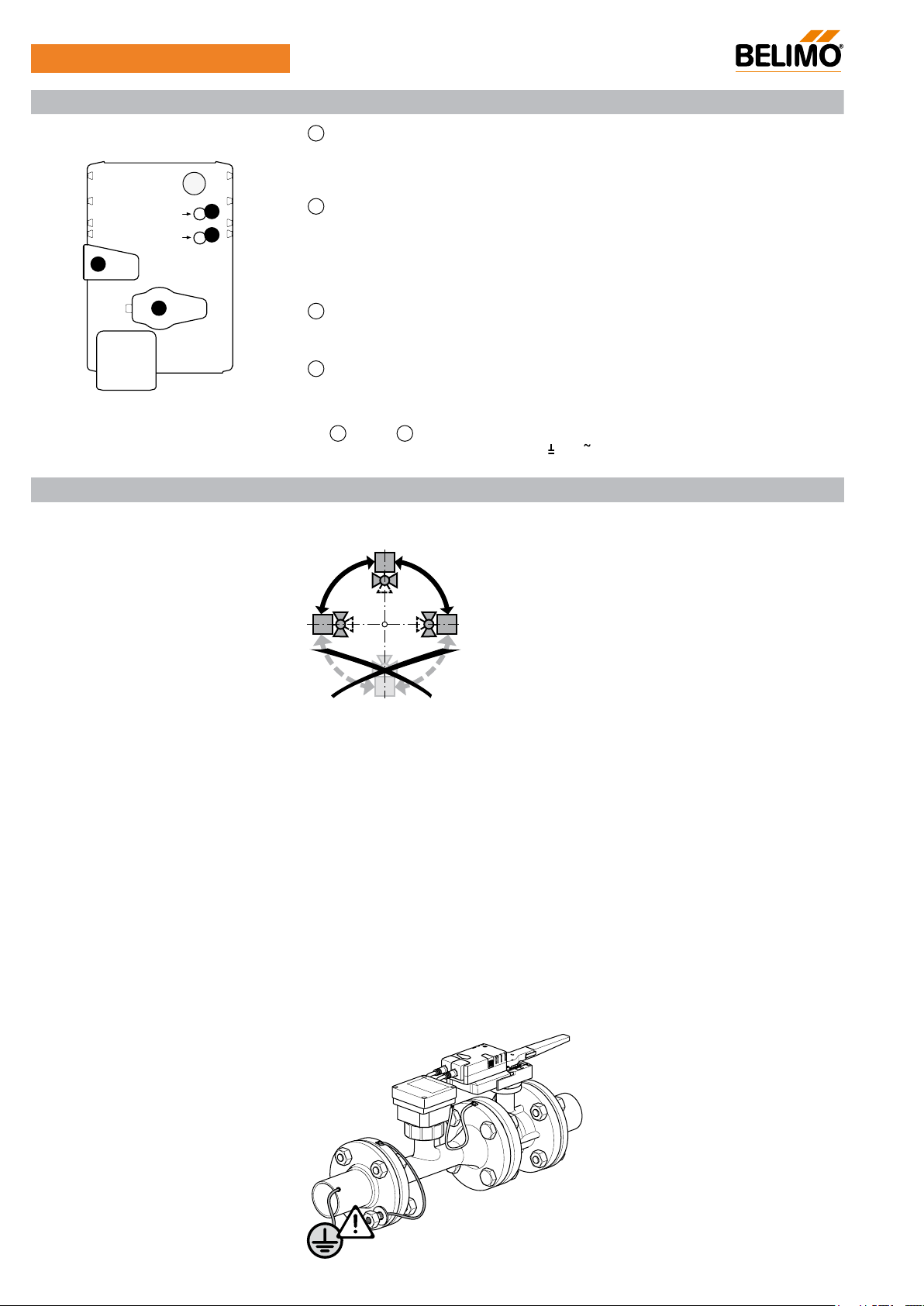
Operating controls and indicators
2
Pushbutton and green LED display
Off:
Illuminated:
Press button:
3
Pushbutton and yellow LED display
Off:
Illuminated:
Blinking:
Press button:
Power
Status
2
3
Adaption
Address
4
Flickering:
5
4
Gear disengagement switch
Press button:
Release button:
5
Service plug
For connecting parameterising and service tools
Check voltage supply connection
2
Off and
Installation notes
Recommended installation positions The ball valve can be installed upright to horizontal. The ball valve may not be installed in a
hanging position, i.e. with the stem pointing downwards.
No voltage supply or malfunction
Operation
Switches on angle of rotation adaption followed by standard operation
Standard operation without MP-Bus
Adaption or synchronising process active
Addressing request sent to MP master
Acknowledgment of addressing
MP communication active
Gear disengaged, motor stops, manual operation possible
Gear engaged, synchronisation starts, followed by standard operation
illuminated:
3
Check the supply connections.
and
Possibly
are swapped over.
90
0°
Installation position in return Installation in the return is recommended.
Water quality requirements The water quality requirements specified in VDI 2035 must be adhered to.
Ball valves are regulating devices. The use of dirt filters is recommended in order to prolong
their service life for performing control tasks.
Maintenance Ball valves, rotary actuators and sensors are maintenance-free.
Before any kind of service work is carried out on the actuator, it is essential to isolate the
rotary actuator from the power supply (by disconnecting the electrical cable). Any pumps
in the part of the piping system concerned must also be switched off and the appropriate
slide valves closed (allow everything to cool down first if necessary and reduce the system
pressure to ambient pressure level).
The system must not be returned to service until the ball valve and the rotary actuator have
been properly reassembled in accordance with the instructions and the pipelines have been
refilled in the proper manner.
Flow direction The direction of flow, specified by an arrow on the housing, is to be complied with, since
otherwise the flow rate will be measured incorrectly.
Earthing Above DN65, it is imperative that the measuring pipe be correctly earthed in order to ensure that
the volumetric flow sensor does not make any unnecessary incorrect measurements.
12
UL marked actuators is optional, please contact your local Sales Representative for details.
V3.3 07.2016•Subject to modifi cation
Page 13
L ≥ 5 x DN
DN L min.
15 5 x 15 mm = 75 mm
20 5 x 20 mm = 100 mm
25 5 x 25 mm = 125 mm
32 5 x 32 mm = 160 mm
40 5 x 40 mm = 200 mm
50 5 x 50 mm = 250 mm
∆p
min
= 100 x
max
k
vs theor.
2
∆p
min
: kPa
max
: m3/h
k
vs theor.
: m3/h
Installation notes
min
= 100 x
max
k
vs theor.
2
= 100 x= 10 kPa
36 m3/h
115 m
3
/h
2
min
= 100 x
max
k
vs theor.
2
= 100 x= 6 kPa
2.07 m3/h
8.6 m
3
/h
2
EP..R+MP / P6..W..E-MP
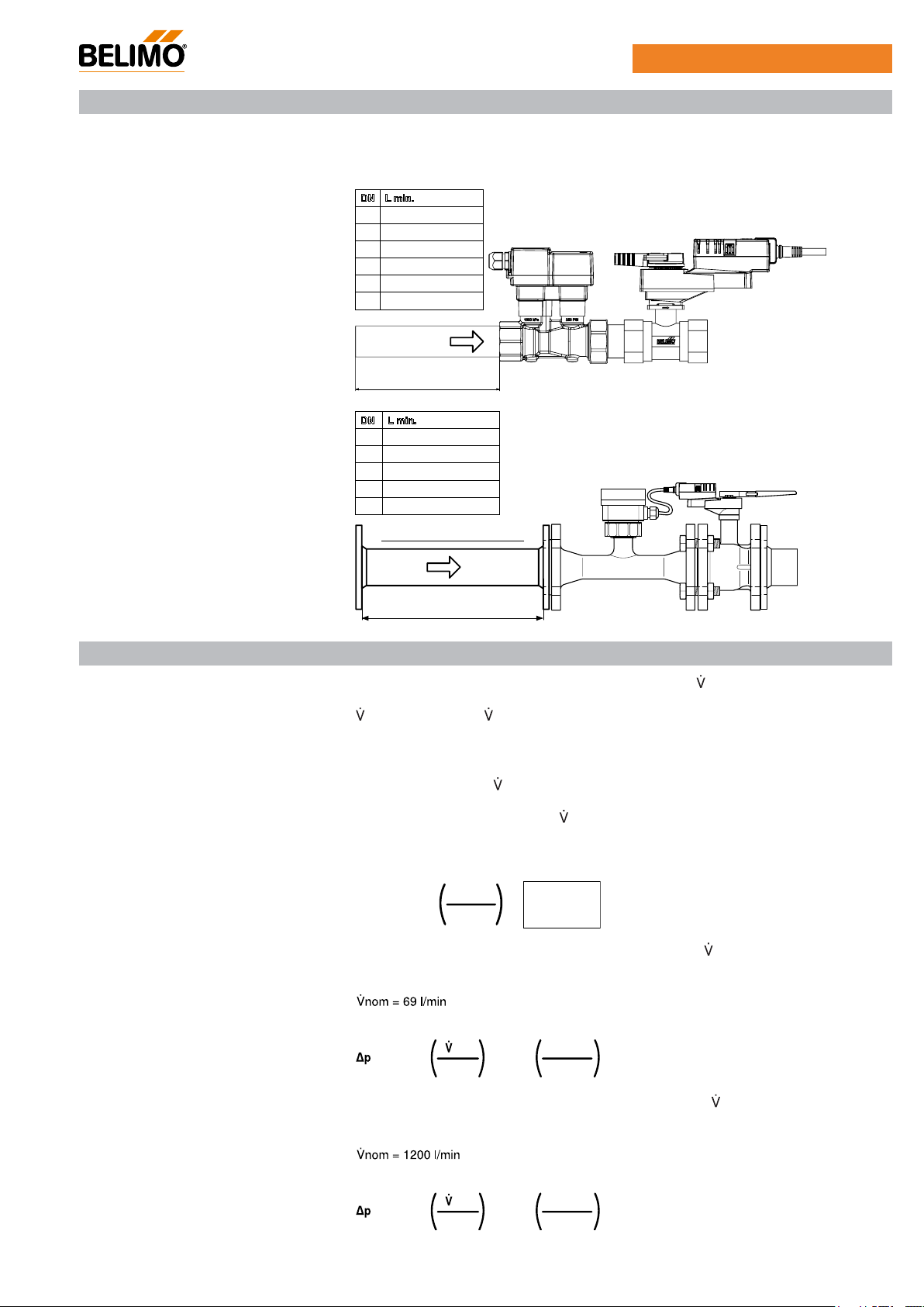
Inlet section
In order to achieve the specified measuring accuracy, a flow-calming section or inflow
section in the direction of the flow is to be provided upstream from the measuring pipe
flange. Its dimensions must be at least 5 x DN.
DN L min.
15 5 x 15 mm = 75 mm
20 5 x 20 mm = 100 mm
25 5 x 25 mm = 125 mm
32 5 x 32 mm = 160 mm
40 5 x 40 mm = 200 mm
50 5 x 50 mm = 250 mm
L ≥5xDN
DN L min.
65 5 x 65 mm = 325 mm
DN L min.
80 5 x 80 mm = 400 mm
65 5 x 65 mm = 325 mm
100 5 x 100 mm = 500 mm
80 5 x 80 mm = 400 mm
125 5 x 125 mm = 625 mm
100 5 x 100 mm = 500 mm
150 5 x 150 mm = 750 mm
125 5 x 125 mm = 625 mm
150 5 x 150 mm = 750 mm
General information
Minimum differential pressure
Valve design
(Pressure drop)
L ≥5xDN
L ≥
5 x DN
The valve is determined using the maximum flow required
max.
A calculation of the kvs value is not required.
max = 30…100% of nom
If no hydraulic data are available, then the same valve DN can be selected as the heat
exchanger nominal diameter.
The minimum required differential pressure (pressure drop via the valve) for achieving the
desired volumetric flow
max can be calculated with the aid of the theoretical kvs value (see
type overview) and the below-mentioned formula. The calculated value is dependent on the
required maximum volumetric flow
max. Higher differential pressures are compensated for
automatically by the valve.
Formula
Example (DN25 with the desired maximum flow rate = 50% nom)
EP025R+MP
kvs theor. = 8.6 m
50% * 69 l/min = 34.5 l/min = 2.07 m /h
3
/h
3
V3.3 07.2016•Subject to modifi cation
Example (DN100 with the desired maximum flow rate = 50%
P6100W2000E-MP
kvs theor. = 115 m /h
3
50% * 1200 l/min = 600 l/min = 36 m /h
UL marked actuators is optional, please contact your local Sales Representative for details.
3
nom)
13
Page 14
L1
L2B
EP..R+MP / P6..W..E-MP
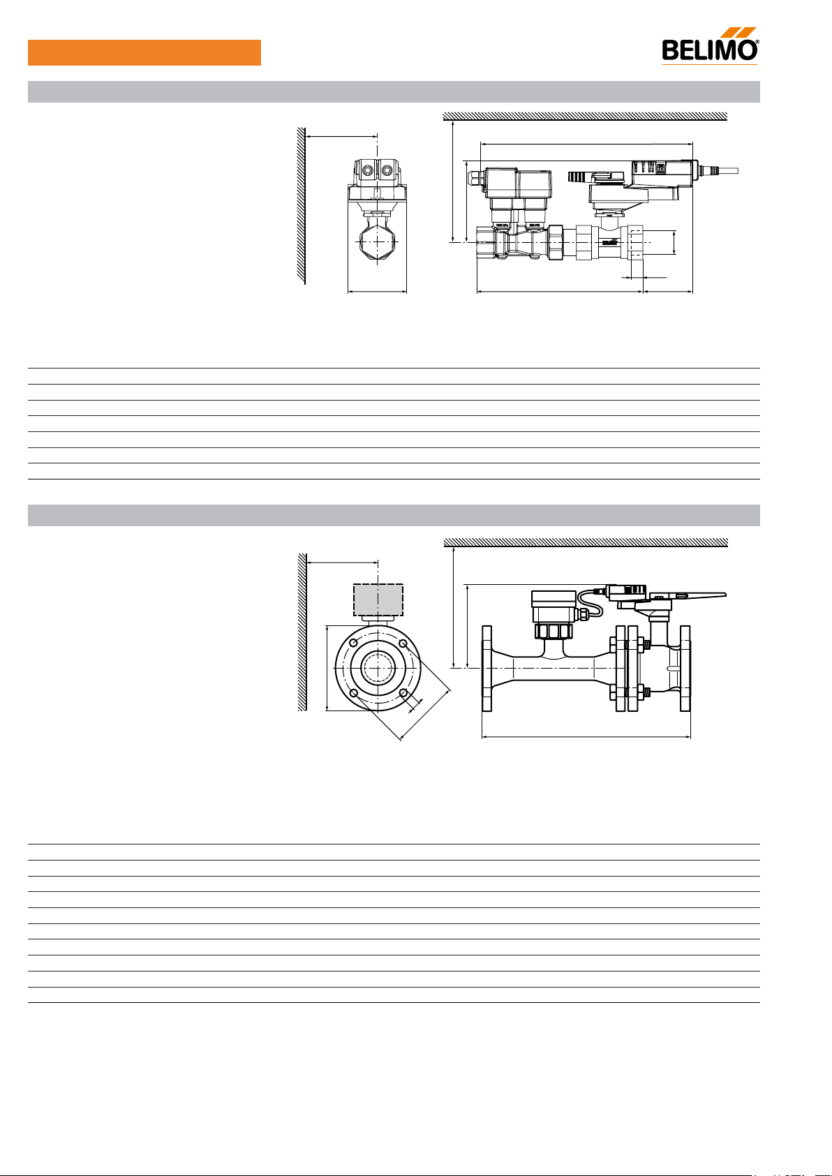
Dimensions [mm] / weight
Dimensional drawings
min. Y
L
min. X
H
Rp
L3
Type DN
[mm]
L
[mm]
L1
[mm]
L2
[mm]
L3
[mm]
B
[mm]
H
[mm]
X
[mm]
Y
[mm]
Weight
approx.
[kg]
EP015R+MP 15 275 192 81 13 75 125 195 77 1.5
EP020R+MP 20 291 211 75 14 75 125 195 77 1.8
EP025R+MP 25 295 230 71 16 75 127 197 77 2.0
EP032R+MP 32 323 255 68 19 85 131 201 77 2.8
EP040R+MP 40 325 267 65 19 85 141 211 77 3.3
EP050R+MP 50 343 288 69 22 95 142 212 77 4.4
EP050R+MP -N 50 343 288 69 22 95 142 212 77 4.4
Dimensions [mm] / weight
Dimensional drawings
min. Y
min. X
H
f
D
d
K
D
f
D
f
L
D
D
If Y <180 mm, then the extension of the hand crank must be dismantled as necessary.
Type DN
[mm]
L
[mm]
H
[mm]
D
[mm]
P6065W800E-MP 65 454 200 185 4 x 19 145 220 150
P6080W1100E-MP 80 499 200 200 8 x 19 160 220 160
P6100W2000E-MP 100 582 220 229 8 x 19 180 240 175
P6125W3100E-MP 125 640 240 252 8 x 19 210 260 190
P6150W4500E-MP 150 767 240 282 8 x 23 240 260 200
P6065W806E-MP 65 454 200 185 4 x 19 145 220 150
P6080W1106E-MP 80 499 200 200 8 x 19 160 220 160
P6100W2006E-MP 100 582 220 229 8 x 19 180 240 175
P6125W3106E-MP 125 640 240 252 8 x 19 210 260 190
P6150W4506E-MP 150 767 240 282 8 x 23 240 260 200
Df refers to flange outside diameter of temporary replaced flow sensor body due to shortage from
*
flow bodies will commence after all the existing stock are used up, please contact your local Sales Representative for details.
14
D
[mm]
f
d
[mm]
K
[mm]
X
[mm]
[mm]
191
210
254
279
318
191
210
254
279
318
the existing supplier. Replacement of the new
UL marked actuators is optional, please contact your local Sales Representative for details.
Y
Weight
approx.
[kg]
28
33
56
68
93
28
33
56
68
93
V3.3 07.2016•Subject to modifi cation
Page 15
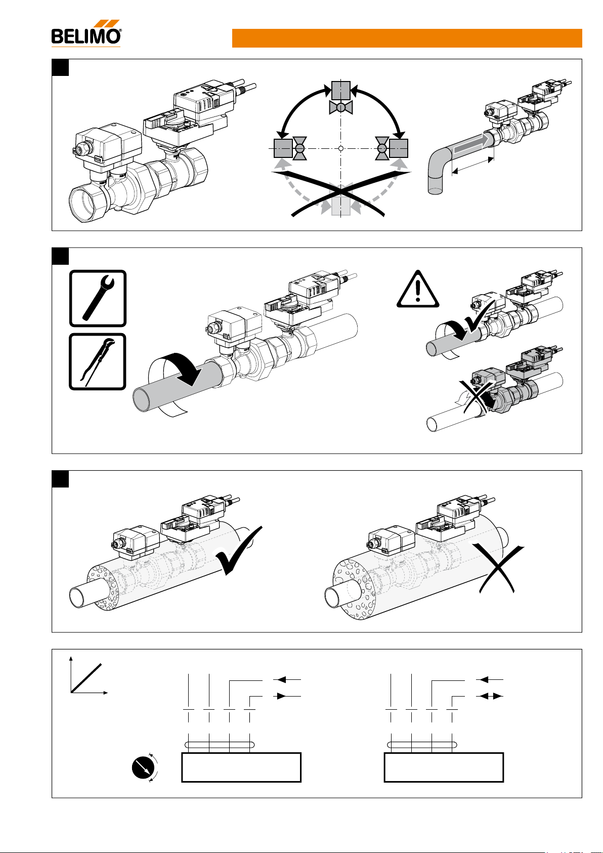
°9
≥ 5 x DN
~
V
V
~
V
Y1
Y2
EP..R+MP Mounting Instructions
!
90
0°
1
!
T
+
–
1
23
Y DC 0 ... 10
U DC 0 ... 10
5
T
–
1
+
23
Y DC 0 ... 10
U MP
5
V3.3 07.2016•Subject to modifi cation
UL marked actuators is optional, please contact your local Sales Representative for details.
15
Page 16
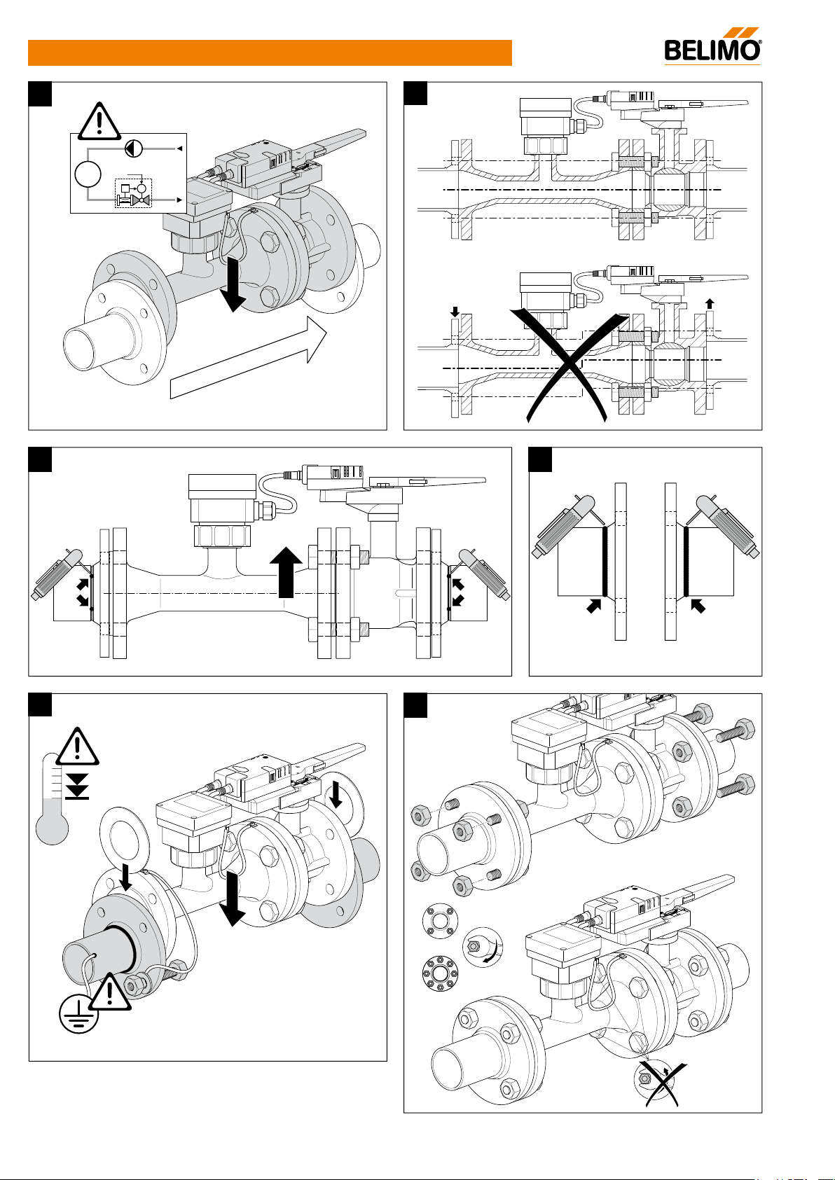
P6..W..E-MP Mounting Instructions
1
Y
M
2
AB
A
3a 3b
2
4
5
11
13
M18: 130 Nm
M20: 190 Nm
42
7
13
65
42
8
16
UL marked actuators is optional, please contact your local Sales Representative for details.
V3.3 07.2016•Subject to modifi cation
Page 17
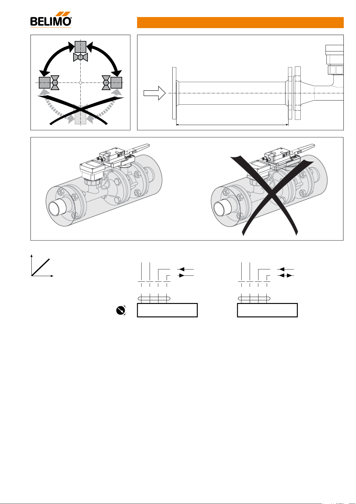
T
~
T
~
Y1
≥ 5
x
DN
90° 90°
P6..W..E-MP Mounting Instructions
AC 24 V / DC 24 V
– +
1 32 5
Y
U
– +
DC (0)2...10V
DC 2...10V
1 32 5
Y
U
Sensor / DC (0)2...10V
MP / DC 2...10V
V3.3 07.2016•Subject to modifi cation
UL marked actuators is optional, please contact your local Sales Representative for details.
17
Page 18
18
Page 19

Market Asia Pacifi c
ASIA PACIFIC HEADQUARTERS
Belimo Actuators Ltd.
Room 1601-6, 16/F, New Commerce Centre
19 On Sum Street, Shatin, N.T., Hong Kong
Tel: +852 2687 1716
Fax: +852 2687 1795
E-mail: info.asiapacifi [email protected]
Belimo AUSTRALIA
Melbourne Offi ce:
Belimo Actuators Pty. Ltd.
12 Enterprise Court
Mulgrave Business Park
Mulgrave, VIC 3170, Australia
Tel: +61 (0)3 8585 7800
Fax: +61 (0)3 8585 7811
E-mail: [email protected]
Brisbane Offi ce:
Belimo Actuators Pty. Ltd.
Unit 26 / 23 Ashtan Place
Banyo, QLD 4014, Australia
Tel: +61 (0)7 3267 1760
Sydney Offi ce:
Belimo Actuators Pty. Ltd.
Suite 2.20, 32 Delhi Road
North Ryde, NSW 2113, Australia
Tel: +61 (0)2 9805 1777
Belimo CHINA
Shanghai Offi ce:
Belimo Actuators (Shanghai) Trading Ltd.
479 Chun Dong Road, Building C-2
Xin Zhuang Industry Park
Shanghai 201108, P.R. China
Tel: +86 21 5483 2929
Fax: +86 21 5483 2930
E-mail: [email protected]
Beijing Offi ce:
Belimo Actuators Ltd.
Unit 1528-1530, 15F, Tower A
Jiatai International Mansion
No. 41, Middle East Fourth Ring Road
Chaoyang District, Beijing,100025,
P.R. China
Tel: +86 10 6462 1382/1386
Fax: +86 10 6462 1383
E-mail: [email protected]
Guangzhou Offi ce:
Belimo Actuators Ltd.
Room 5217-5218, China International Centre,
Tower B, 33 Zhong Shan San Road, Yuexiu District,
Guangzhou 510055, P.R. China
Tel: +86 20 3435 1860
Fax: +86 20 3435 1870
E-mail: [email protected]
Belimo HONG KONG
Hong Kong Offi ce:
Belimo Actuators Ltd.
Room 1601-6, 16/F, New Commerce Centre
19 On Sum Street, Shatin, N.T., Hong Kong
Tel: +852 2687 1716
Fax: +852 2687 1795
E-mail: [email protected]
Indonesia Offi ce:
Belimo Actuators Ltd.
Graha Kencana Building 8th Floor Block B
Jl. Raya Perjuangan 88
Kebon Jeruk - Jakarta Barat 11530, Indonesia
Tel: +62 21 5367 8278
Fax: +62 21 5366 0688
E-mail: [email protected]
Japan Offi ce:
Belimo Actuators Ltd.
2nd Floor, Yamaki Building III
3-1-5 Azumabashi, Sumida-ku
Tokyo 130-0001, Japan
Tel: +81 3 6823 6961
Fax: +81 3 3626 3911
E-mail: [email protected]
Malaysia Offi ce:
Belimo Actuators Ltd
S-13-12, First Subang, Jalan SS15/4G
47500 Subang Jaya, Selangor, Malaysia
Tel: +03-56125833
Fax: +03-56125233
E-mail: [email protected]
Singapore Offi ce
Belimo Actuators Ltd.
1 Tannery Road #08-04
One Tannery, Singapore 347719
Tel: +65 6842 1626
Fax: +65 6842 1630
E-mail: [email protected]
Taiwan Offi ce:
Belimo Actuators Ltd.
7F-2, No.343, Jhonghe Rd., Yonghe District
New Taipei City 234, Taiwan
Tel: +886 2 2922 8805
Fax: +886 2 2922 8806
E-mail: [email protected]
Thailand Offi ce:
Belimo Actuators Ltd.
90/2 Pensiri Place, Soi Phaholyothin 32
Phaholyothin Road, Chandrakasem, Jatujak
Bangkok 10900, Thailand
Tel: +662 9415582-3
Fax: +662 9415584
E-mail: [email protected]
Belimo INDIA
Mumbai Offi ce:
Belimo Actuators India Pvt. Ltd.
23/ ABCD, Govt. Industrial Estate, Charkop
Kandivali West, Mumbai 400067, India
Tel: +91 22 4025 4800
Fax: +91 22 4025 4899
E-mail: [email protected]
Bangalore offi ce:
Belimo Actuators India Pvt. Ltd.
Sreerama Complex, No. 13, 2nd Floor
5th Cross Road, 6th Block, Koramangala
Bangalore – 560097, India
Tel: +91-80-40906311
Fax: +91-80-40906288
E-mail: [email protected]
New Delhi Offi ce:
Belimo Actuators India Pvt. Ltd.
Flat No. 515, DLF Tower – B
Jasola Distt. Centre, Jasola
New Delhi 110025, India
Tel: +91 11 41078501
Fax: +91 11 41078508
E-mail: [email protected]
Chennai Offi ce:
Belimo Actuators India Pvt. Ltd.
Flat no.3B, Urmilla House
#15, ARK Colony, Eldams Road
Chennai-600 018, India
Tel: +91 44 24355154/5153
E-mail: [email protected]
19
Page 20
Innovation, Quality
VALVE
and Consultancy:
A partnership for
motorising HVAC
actuators
Belimo regional head offi ces
EU BELIMO Automation AG
Brunnenbachstrasse 1
8340 Hinwil, Switzerland
Tel: +41 43 843 61 11
Fax: +41 43 843 62 68
E-mail: [email protected]
AP Belimo Actuators Ltd.
Room 1601-6, 16/F, New Commerce Centre
19 On Sum Street, Shatin, N.T., Hong Kong
Tel: +852 2687 1716
Fax: +852 2687 1795
E-mail: info.asiapacifi [email protected]
US BELIMO Aircontrol (USA), Inc.
33 Turner Road
Danbury, CT 06810
USA
Tel: +800 543-9038 / 203 791-9915
Fax: +800 228-8283 / 203 791-9919
93010-00168
Or contact your nearest Sales Representative
www.belimo.com
 Loading...