

Page 1
4. A1-PC-T V2.1 NMV-D2M 11.02.04/EN
PC-Tool - Module NMV-D2M V2.1
OEM
3.5V
VDC
Page 2

2
4A1PC-T V2.1 NMV-D2M-EN 11-02-04.doc PM VAV - Subject to technical changes
VAV – Module NMV-D2M
VAV-Compact - Product Information
Full technical information on VAV-Compact products will be found in the
following documentation:
4. NMV-D2M
Product Information
Air Volume Control VAV-Compact
The documentation is structured by subject and provides the following detail information:
Please contact your local Belimo agent or representative for more information and the latest VAV documentation.
All Belimo product documentation (in pdf format) can be downloaded from
www.belimo.ch
Technical
data
Selecting a
syst em
kontrolle
atibilität
Tools
MFT
Bus
Klassisch
Funktionen
Tools
Compatibili ty
Setting up
Daten
Product
overview
Functions
Application
Classic Bus
Functional
testing
Overview
Contents 3 - 4
N-A Applications 5 - 20
N-E Expert 21 - 24
N-S Service 25 - 37
N-D Diagnosis 38 - 47
N-M Miscellaneous 48
Page 3

3
4A1PC-T V2.1 NMV-D2M-EN 11-02-04.doc PM VAV - Subject to technical changes
VAV – Module NMV-D2M
Contents Designation N-...
Applications ______________________________________________________________ N-A
VAV-Compact NMV-D2M........................................................................................................N-A1
Customised versions..................................................................................N-A1.1
Support for..................................................................................................N-A1.2
Communication links to the NMV-D2M ...................................................................................N-A2
Local connection via diagnostic socket.....................................................N-A2.1
Direct connection to control cabinet or connection box............................N-A2.2
Connection in a bus system.......................................................................N-A2.3
Module NMV-D2M: General ...................................................................................................N-A3
Purpose....................................................................................................... N-A3.1
Description of the elements........................................................................N-A3.2
Operator interface N-A3.2.1
Description of the menu bar N-A3.2.2
Menu functions / Function keys N-A3.2.3
Description of the toolbar N-A3.2.4
Description of the buttons N-A3.2.5
‘Actuator symbol’ (data comparison) N-A3.2.6
Seal-bit function N-A3.2.7
Status line N-A3.2.8
Select required actuator (bus mode) N-A3.2.9
Basic functions..........................................................................................................................N-A4
Print <CTRL> <P>..................................................................................... N-A4.1
Addressing <F2>....................................................................................... N-A4.2
Address setting PP / MP N-A4.2.1
Methods of addressing N-A4.2.2
- by manual disengagement button N-A4.2.3
- according to serial number N-A4.2.4
Reset to OEM settin g <F5>.......................................................................N-A4.3
Log Data display <F3>............................................................................................................N-A5
Log data – Description of the elements..................................................... N-A5.1
Log file.........................................................................................................N-A5.2
Procedure N-A5.2.1
Access to previous months N-A5.2.2
File structure............................................................................................... N-A5.3
File name N-A5.3.1
Storage directory (path) N-A5.3.2
Trend recall <F6>....................................................................................................................N-A6
Project Data form <F4>...........................................................................................................N-A7
Data fields...................................................................................................N-A7.1
Procedure....................................................................................................N-A7.2
Extras ¦ Options ¦ NMV-D2M....................................................................................................N-A8
NMV-D2M password.................................................................................. N-A8.1
Flow unit......................................................................................................N-A8.2
Label printer................................................................................................N-A8.3
Box-Type – File selection...........................................................................N-A8.4
Log data - path selection............................................................................N-A8.5
Trend data - path selection........................................................................N-A8.6
Test-Sequence – File selection .................................................................N-A8.7
Help...........................................................................................................................................N-A9
Help entries................................................................................................. N-A9.1
About Belimo PC-Tool................................................................................ N-A9.2
Expert _ _________________________________________________________________ N-E
Using the ‘Expert’ register ........................................................................................................N-E1
Control Signal / Direction of rotation........................................................................................N-E2
Control signal.............................................................................................. N-E2.1
Reference signal (w) N-E2.1.1
Actual volumetric flow signal (U5) N-E2.12.
Sensor connection N-E2.1.3
Page 4

4
4A1PC-T V2.1 NMV-D2M-EN 11-02-04.doc PM VAV - Subject to technical changes
VAV – Module NMV-D2M
Mode ........................................................................................................... N-E2.2
Direction of rotation, damper opening....................................................... N-E2.3
Actuator settings.......................................................................................................................N-E3
Adaption...................................................................................................... N-E3.1
Synchronisation .......................................................................................... N-E3.2
Torque......................................................................................................... N-E3.3
NMV-D2M versions data............................................................................ N-E3.4
Adaption....................................................................................................................................N-E4
Service___________________________________________________________________ N-S
Settings.....................................................................................................................................N-S1
V’nom.......................................................................................................... N-S1.1
Adjusting the operating value of volumetric flow...................................... N-S1.2
Position.......................................................................................................N-S1.3
NMV-D2M information ............................................................................................................. N-S2
OEM............................................................................................................ N-S2.1
Operating time............................................................................................ N-S2.2
Active time.................................................................................................. N-S2.3
Stop&Go ratio............................................................................................. N-S2.4
Calibration value......................................................................................... N-S2.5
Alarms ......................................................................................................... N-S2.6
Operation..................................................................................................................................N-S3
Enable ‘OPERATION’ ................................................................................ N-S3.1
Disable ‘OPERATION’ ............................................................................... N-S3.2
Status information....................................................................................... N-S3.3
Local override control.................................................................................N-S3.4
Operating steps.......................................................................................... N-S3.5
Reference / Actual value of damper position............................................ N-S3.6
Trend......................................................................................................................................... N-S4
Trend – Description of the elements ......................................................... N-S4.1
Live trend.................................................................................................... N-S4.2
Start/Stop N-S4.2.1
Selecting the operating step N-S4.2.2
Voltage readings in ‘Live Trend’ N-S4.2.3
Trend file ..................................................................................................... N-S4.3
File name N-S4.3.1
Storage directory (path) N-S4.3.2
Trend Recall <F6>.....................................................................................N-S4.4
Read Trend file N-S4.4.1
Test ...........................................................................................................................................N-S5
Test-Sequence ........................................................................................... N-S5.1
Start/Stop N-S5.1.1
‘Test’ – Diagnosis....................................................................................... N-S5.2
Status display – Step control ..................................................................... N-S5.3
Description of the elements....................................................................... N-S5.4
Selecting the operating step...................................................................... N-S5.5
Display of actual values ............................................................................. N-S5.6
Voltage display in ‘Live Trend’ N-S5.6.1
Selecting the Test-Sequence..................................................................... N-S5.7
Available Test-Sequences N-S5.7.1
Test log (Trend file).................................................................................... N-S5.8
File name N-S5.8.1
Storage directory (path) N-S5.8.2
Read Test log (Trend Recall <F6>)........................................................... N-S5.9
Diagnosis ________________________________________________________________ N-P
Index of recorded Test-Sequences.........................................................................................N-P1
Miscellaneous_____________________________________________________________ N-M
Function checks of the NMV-D2M...........................................................................................N-M1
‘Level 2’ function check.............................................................................. N-M1.1
‘Level 3’ function check.............................................................................. N-M1.2
Formulae................................................................................................................................... N-M2
Page 5
5
4A1PC-T V2.1 NMV-D2M-EN 11-02-04.doc PM VAV - Subject to technical changes
VAV – Module NMV-D2M
N-A Applications
N-A 1 VAV-Compact NMV-D2M
The PC-Tool Module NMV-D2M has been d esigned specifically for the
VAV-Compact NMV-D2M and its use in connection with CAV and VAV air
boxes.
N-A1.1 Customised versions
Belimo VAV-Compact controllers are control devices that have been
manufactured for specific customers and are produced individually for
various air box manufacturers (OEMs). Therefore, each version is an optimum match for the components used by particular manufacturers, such
as measuring transducers, damper spindles and mounting systems.
Some customised versions have different operating step control systems
than the standard NMV-D2M. The technical documentation p rovided b y
the manufacturers of the air boxes should be given close attention.
N-A 1.2 Support for …
… VAV-Compact NMV-D2 / NMV-24V / NMV-24D
These device s are not sold any more and are not supported by PC-Tool
V2.
... VAV-Universal VRD2 / VRD2-L / VRP / VRP-STP
are not supported by PC-Tool V2.
... VAV ...24-MFT2 actuators
These actuator types need the MFT -PC Module of PC-Tool.
Therefore, please change over to the appropriate module.
... VAV ...24 V actuators
These types are pure VAV actuators from the VAV-Universal range and
are not supported by PC-Tool V2.
Designation of customised versions
NMV-D2M xxx
Customer designation
Basic product
Changing old Belimo VAV controllers
When planning to change old Belimo VAV controllers
such as VR1, VR2, NMV24-D and NMV24-V first get in
touch with your local Belimo agent or representative !
Page 6

6
4A1PC-T V2.1 NMV-D2M-EN 11-02-04.doc PM VAV - Subject to technical changes
VAV – Module NMV-D2M
N-A2 Communication links to the NMV-D2M
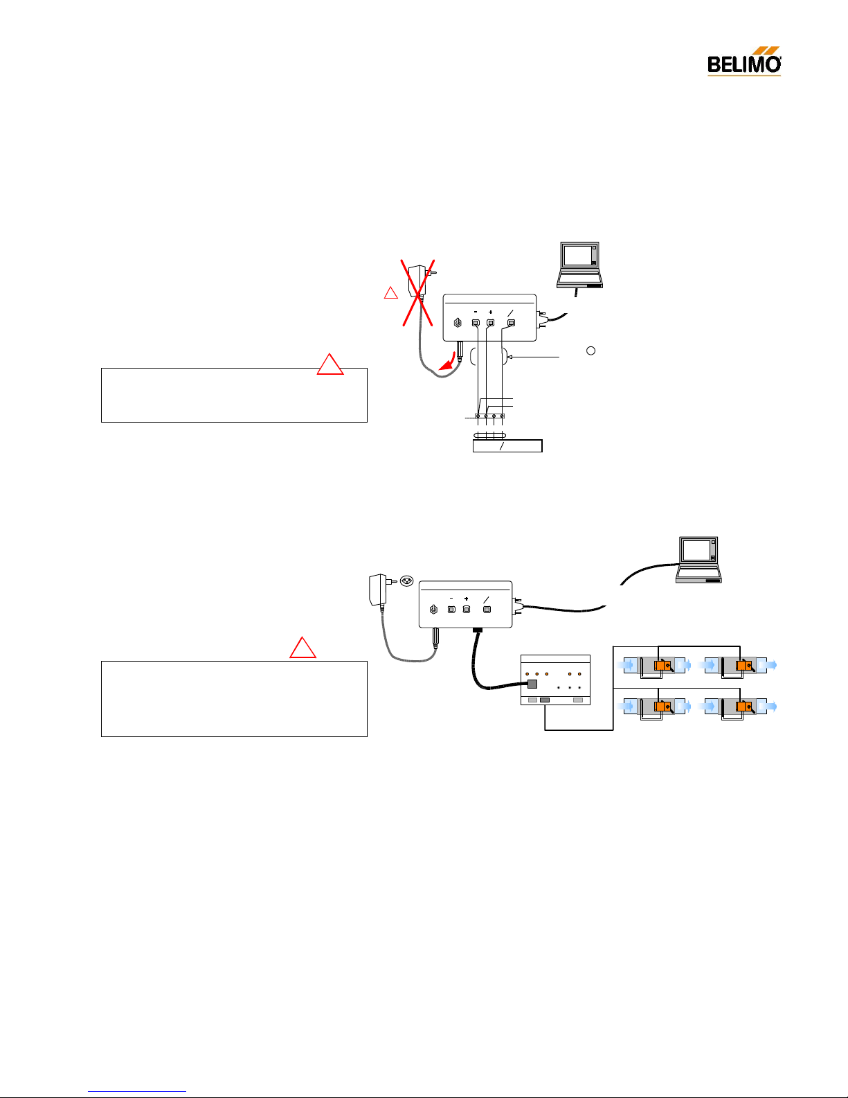
The NMV-D2M c an be connected to a PC through a ZIP-RS232 or ZIP232-KA interface unit. There are various alternative types of cable (b and
c) available f rom the ZKS-VAV cable sets for making on-site connections
with the combination of the ZIP-RS232.
N-A2.1 Local connection via diagnostic socket
wsswrt
NMV-D2M powered from installation
AC 24 V
ZIP-RS232
1
2 5
OFF
Actuator
RS232
ON
U
PP
~
T
Beli mo
PC-Tool
Cable f rom
kit ZIP-RS232
NMV-D2M
AC 230 V
ZN230-24
Cable
from kit ZKS-VAV
b
!
Power supply AC/DC 24 V
Duplicated NMV-D2M power supply !
The NMV-
D2M must not have a duplicated power
supply! When using this method of connection re-
move the AC 24 V plug from the ZIP-RS232 unit.
!
NMV-D2M powered from installation
Belimo
PC-Tool
Cable RS232 1:1
D-Sub female-female
NMV-D2M
Kabel :
ZK1-VAV
Power supply AC/DC 24 V
Rx/ Tx
Enable
Power
ZIP -2 32- KA
ZIP- 232-KA
Detailed information about the MP-bus interface
- ZIP-232-KA
- ZIP-RS232
can be found in the data sheet ZIP-232-KA and ZIPRS232.
Page 7
7
4A1PC-T V2.1 NMV-D2M-EN 11-02-04.doc PM VAV - Subject to technical changes
VAV – Module NMV-D2M
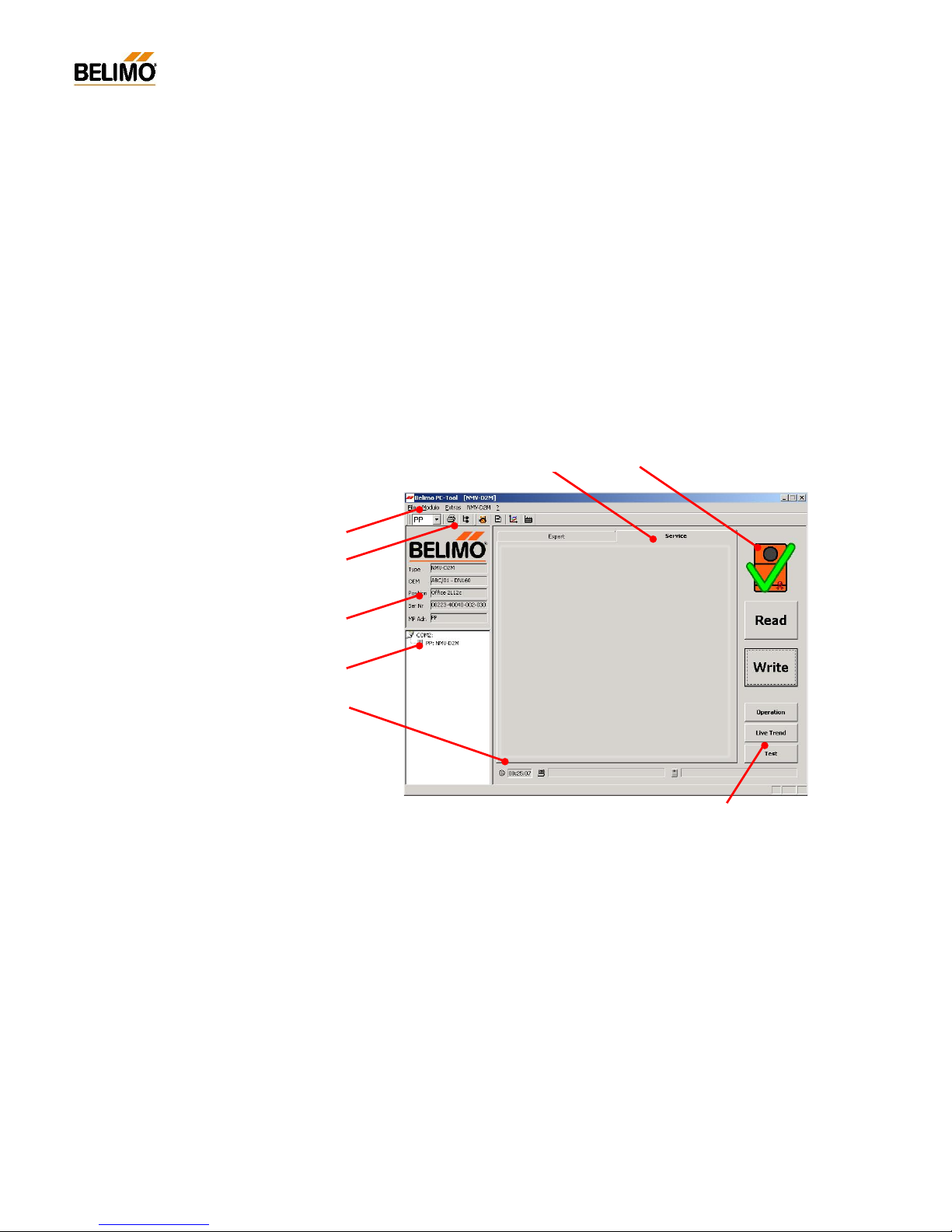
N-A2.2 Direct connection to control cabinet or
connection box
N-A2.3 Connection in a bus system
NMV-D2M powered from installation
wsswrt
AC 24 V
ZIP-RS232
1
2 5
OFF
Actuator
RS232
ON
U
PP
~
T
AC 230 V
ZN230-24
~
T
+
_
5321
NMV- D2 M
U
PP
w
~ T
+
_
AC/ DC 24 V
Belimo
PC-Tool
Cable from
kit ZIP-RS232
Cable
from kit ZKS-VAV
c
!
control cabinet or
connecti on box
NMV-D2M powered via bus cable
MP-Bus
Cable from
kit ZIP-RS232
Cable from
kit ZIP-RS232
Belimo
PC-Tool
MP ...
MP 8
-+
-+
MP 1
MP ...
-+
-+
AC 230 V
ZN230-24
AC 24 V
ZIP-RS232
1 2 5
OFF
Actu at or
RS232
ON
U
PP
~
T
UK24 LON
BELI MO
2
Connecting PC-Tool to the bus system !
In bus mode no tools may be operated through the
communications socket of the NMV-
D2M. For this
application the connection is made directly to the
UK24LON unit or the DDC system.
!
Duplicated NMV-D2M power supply !
The NMV-
D2M must not have a duplicated power
supply! When using this method of connection re-
move the AC 24 V plug from the ZIP-RS232 unit.
!
Detailed information about the MP-bus interface
ZIP-RS232 can be found in the da ta sheet ZIP-RS232.
Page 8
8
4A1PC-T V2.1 NMV-D2M-EN 11-02-04.doc PM VAV - Subject to technical changes
VAV – Module NMV-D2M
N-A3 Module NMV-D2M: General
N-A3.1 Purpose
Module NMV-D2M is used specifically for VAV air bo xes to operate and
assign parameters to the Belimo VAV-Compact NMV-D2M controller. The
functions are shared between the two ‘Service’ and ‘Expert’ registers depending on the particular application.
In addition to these two registers the module also offers users a variety of
basic functions. This chapter describes each of those functions in detail.
N-A3.2 Description of the elements
N-A3.2.1 Operator interface
Menu bar
Toolbar
Actuator ident ifier
Active communication link
Status line
Buttons
Data comparisonRegister
Page 9

9
4A1PC-T V2.1 NMV-D2M-EN 11-02-04.doc PM VAV - Subject to technical changes
VAV – Module NMV-D2M
N-A3.2.2 Description of the menu bar
N-A3.2.3 Menu functions / Function keys
Menu entry Brief description Function key
File
¦ Print… Controller settings of active <CTRL> <P>
¦ NMV-D2M are printed out
¦ Print to file… Controller settings of active <CTRL> <shift> <P>
¦ NMV-D2M are stored in a text file
¦ Printer setting… Printer option
¦ Windows function
¦ End Close program <ALT> <F4>
Menu entry Brief description Function key
Module
¦ MFT-PC Module for assigning parameters to Belimo MFT actuators,
¦ such as AM24-MFT, AF24-MFT, etc.
¦ NMV -D2M VAV module for VAV-Compact NMV-D2M controllers
Menu entry Brief description Function key
Extras
¦ Address actuators… F2 Change address assigned to NMV-D2M <F2>
¦ Options...
¦ General
¦ - Language Select program language
¦ - Com Port Set communication Port 1...4
¦ - Module release Activate special functions (only for manufacturers)
¦ MFT-PC
¦ - Actuator password Activate password function
¦ NMV-D2M
¦ -
NMV-D2M password Activate password function
¦ - Flow unit Display volumetric flow in m3/h / l/s / cfm
¦ - Label printer Activate label printer (only for manufacturers)
¦ - Box-Type Select Box-Type file (only for manufacturers)
¦ - Log data Select storage directory
¦ - Trend data Select storage directory
¦ - Test-Sequence Select Test-Sequence file
Menu entry Brief description Function key
NMV-D2M
¦ Reset to OEM setting Reset operating flow settings to <F5>
¦ OEM default values
¦ Log Data display Show log file <F3>
¦ Trend Recall Display stored trend data <F6>
¦ Project Data form Open input screen mask for project data <F4>
¦ for trend, log, test and print functions
¦ Select Test sequence… Browse option for the selection of <F7>
Test sequence
Page 10
10
4A1PC-T V2.1 NMV-D2M-EN 11-02-04.doc PM VAV - Subject to technical changes
VAV – Module NMV-D2M
Screen data and NMV-D2M data do not agree:
a) Read data not executed
b) Screen data changed but Write data not e xecuted
Screen data and NMV-D2M data agree.
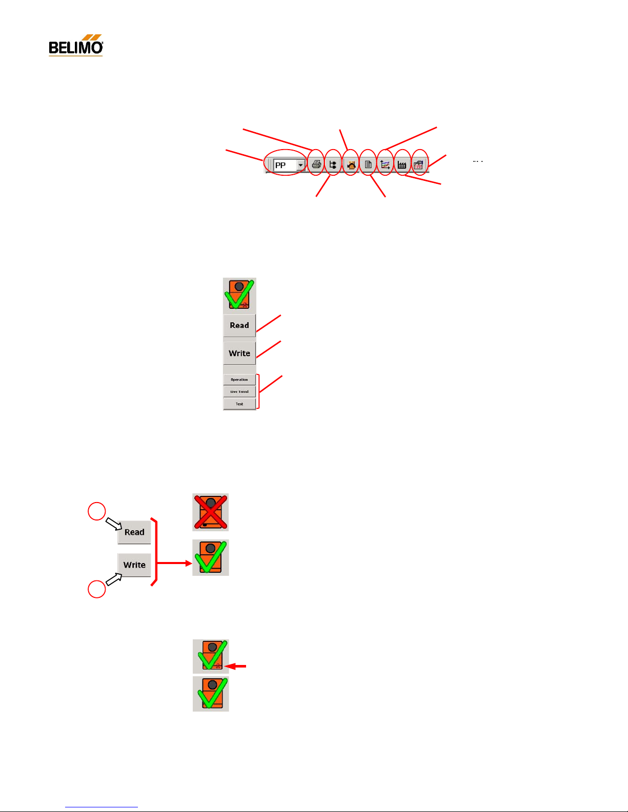
N-A3.2.4 Description of the toolbar
N-A2.3.5 Description of the buttons
The buttons are adapted to suit the various directories.
N-A3.2.6 ‘Actuator symbol’ (data comparison)
The large NMV-D2M symbol, above the buttons, shows the consistency
of data between the connected NMV-D2M and the scree n display.
N-A3.2.7 Seal-bit function
The settings of operating flow rate programmed by the manufacturer
V’min, V’mid and V’max are flagged by the so-called ‘seal bit’. If any of
these values are adjusted on-site it will be indicated by the ‘broken seal
bit’ symbol. The manufacturer’s value (OEM defaults) can be reset at any
time with the <F5> f unction‚ OEM defaults’. However, the seal bit cannot
be reset by the user.
When used in the MP-Bus system:
‘Select required actuator’
[MP1 ... 8]
Print parameters <CTRL> <P> Reset to OEM setting <F5> Trend Recall <F6>
Address NMV-
D2M <F2>
Display Log Data <F3>
Project Data form <F4>
Read:
Reading parameters from the connected NMV-D2M controller.
Write:
Writing changed parameters to the connected NMV-D2M controller.
Buttons:
See ‘Experts‘ and ‘Service‘ descriptions.
a
b
Select Test
sequence <F7>
Page 11
11
4A1PC-T V2.1 NMV-D2M-EN 11-02-04.doc PM VAV - Subject to technical changes
VAV – Module NMV-D2M
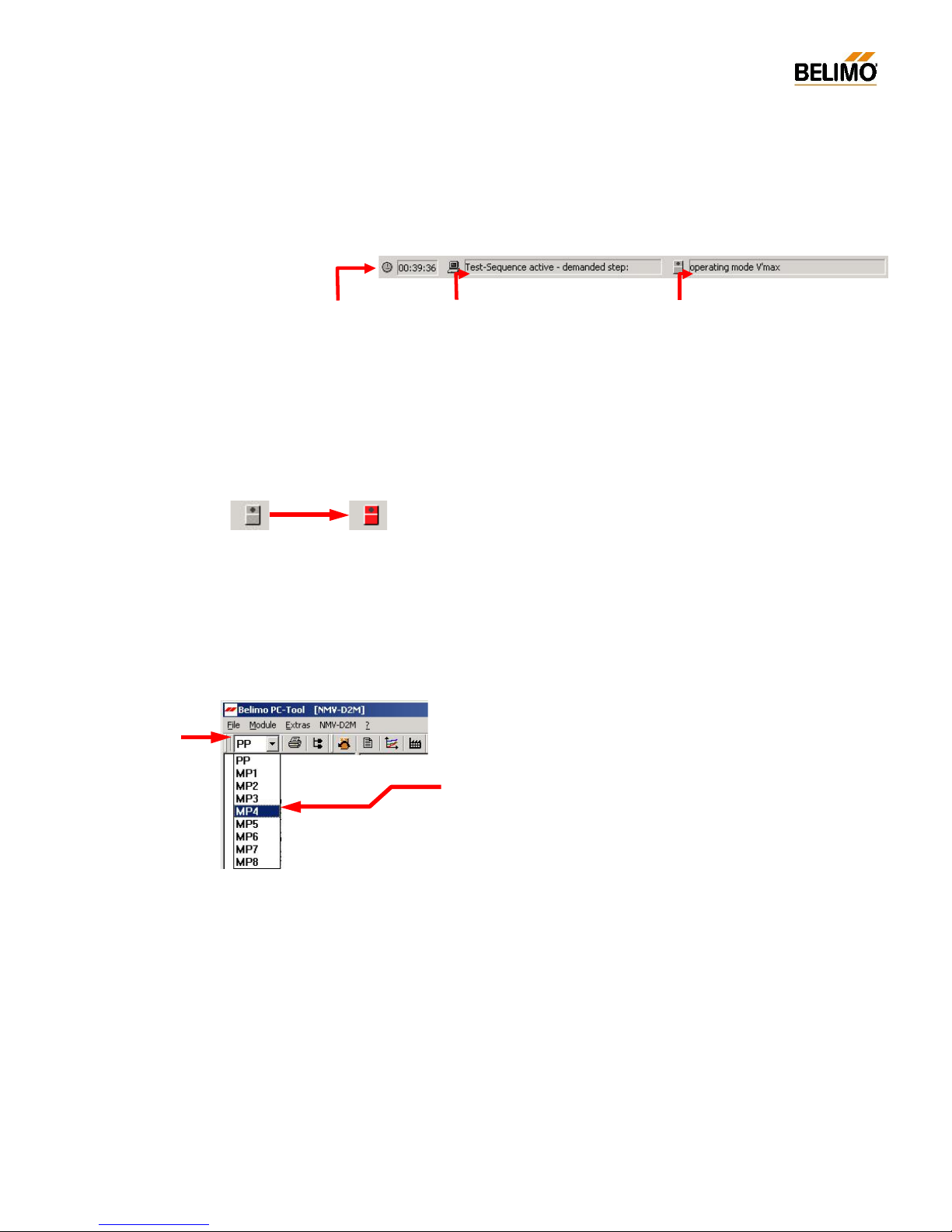
N-A3.2.8 Status line
The active program and the status of the NMV-D2M are indicated on this
line.
NMV-D2M Status indicator – red symbol
If the NMV-D2M cannot be overridden by the PC-Tool it will be indicated
by a red actuator symbol. The following states are indicated:
- Adaption active (triggered locally or via the PC-Tool)
- Synchronisation active
- Local override control active, e.g. CAV ‘Close’ step
N-A3.2.9 Select required actuator (bus mode)
Open address wind o w
Select required ad dress, e.g. MP4
The selected active communication link is shown in the actuator identifier.
Duration of link
hh:mm:ss
Program status
- Read data
- Write data
- Operation active
- Trend data recording active
- Test-Sequence – check system pressure
- Test-Sequence active – demanded step
- ...
NMV-D2M status
- Adaption / Synchronising active
- Motor s top
- Damper opening / closing
- V’m in / V’mid / V’max active
- operating mode V’nom
- Auto [reference input w]
- Variab le cont rol V’mi n... V’m ax
- Local override control active
- ...
Normal
No control function
possible
e.g.
synchronisation
active
Page 12
12
4A1PC-T V2.1 NMV-D2M-EN 11-02-04.doc PM VAV - Subject to technical changes
VAV – Module NMV-D2M
N-A4 Basic functions
The basic functions described below are available in all directories.
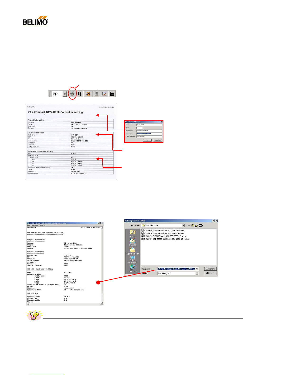
N-A4.1 Print controller date
N-A4.1.1 Print <CTRL> <P>
The following data and s ettings of the active NMV-D2M are printed:
- Project information <F4>
Project-specific information: this is not NMV-D2M data but entries from the ‘Acquire
project data’ inpu t screen mask.
Note: The data of the this screen mask remains
valid until the relevant fields are deleted or overwritten.
- Equipment information
Type / OEM info / Position / Serial number / MP address / Version designation
- NMV-D2M controller settings
Mod e / Oper atin g flow r ate se tti ng (c alibr atio n value / V ’no m / V’ max, V’ mid , V ’min)
/ Direction of rotation / Torque / Adaption an d synchronisation
N-A4.1.2 Print to file <Shift> <CTRL> <P>
The data from the connected NMV-D2M xxx gets stored in a text file:
The created text file name defaults to :
- layout: NMV-D2M_serialnumber_date.TXT
z.B.: NMV-D2M_00223-40039-002-033_2004-01-08.txt
Name and directory might be changed by demand.
Print <CNTRL> <P>
Practical tip – Project documentatio n
A fast a nd easy way to create the project documentation: save the data of the VAV controller to your PC’s hard disk by the use of the
‘Print to file’ feature and print or store them afterwards in your office.
Page 13
13
4A1PC-T V2.1 NMV-D2M-EN 11-02-04.doc PM VAV - Subject to technical changes
VAV – Module NMV-D2M
Connect via safety
isolating transformer
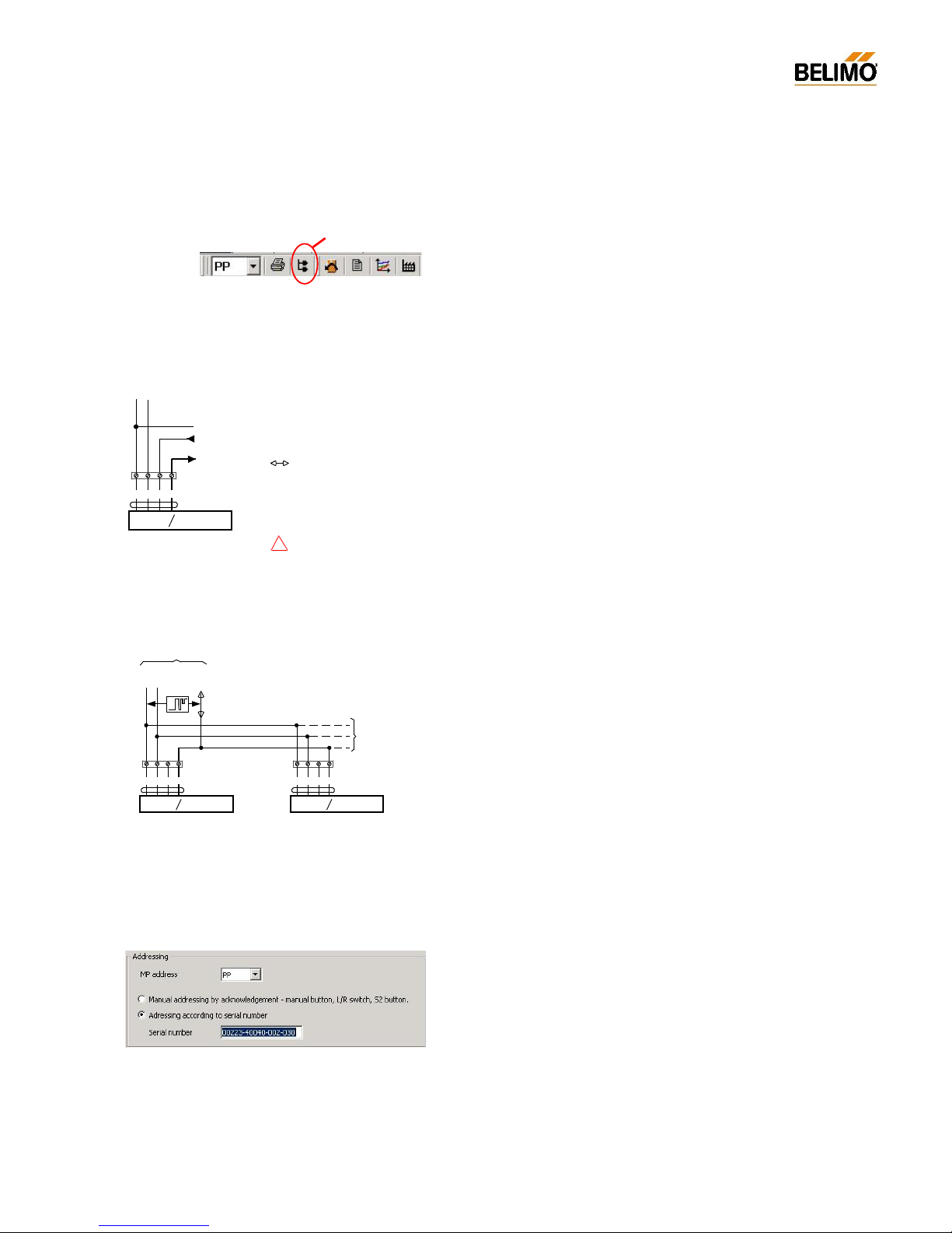
N-A4.2 Addressing <F2>
Conventional mode address: PP
When several NMV-D2M’s or MFT(2) actuators communicate over the
MP-Bus the y must be clearly identifiab le.
Bus mode address: MP1...MP8
N-A4.2.1 Address setting PP / MP
- Conventional mode setting ‘PP’ (Point-to-Point)
The ‘PP’ address is selected when an NMV-D2M under conventional control is connected to the PC-Tool.
See Connection diagram N-A2.1 and N-A2.2.
When an NMV-D2M is addressed ‘PP’ it is automatically assigned parameters for conventional mode.
For VAV, modulating control is ef fected with 0/2...10 V DC or, for CAV, by
means of step control. The signal for the actual value of volumetric flow
U5 is available at Terminal 5.
An NMV-D2M set for bus mode (MP) can be reset for conventional control
by addressing for ‘PP’.
- Bus mode setting ‘MP’ (Multi-Point)
Address ‘MP1...MP8’ is selected when several NMV-D2M’s or other Belimo MFT(2) actuators are incorporated into a higher level system via the
MP-Bus. In this case the connection is always made at the bus interface,
e.g. UK24LON and never directly to the communication socket of the
NMV-D2M. See Connection diagram N-A2.3.
If an NMV-D2M is given an MP address ‘MP1...MP8’ it will automatically
be assigned parameters for MP-Bus operation. I n this case control is effected digitally over the MP-Bus.
N-A4.2.2 Methods of addressing
The screen mask for addressing the NMV-D2M is called from the menu,
the toolbar or the <F2> function key.
There are two methods available:
- Addressing by manual disengagement push-button
- Addressing according to serial number
MP
~
T
+
_
AC 24 V
DC 24 V
5321
NMV-D2M
U
MP
w
~ T
+
_
5321
NMV-D2M
U
MP
w
~ T
+
_
Further
NMV-D2M or
MFT2 actuators
UKK24LON
or
DDC with MP-Bus interface
5321
NMV-D2M
U
MP
w
~ T
+
_
Reference valu e inp ut w
Actual vol umetric flow signal U
5
PP-Communication Tool
T
AC 24 V
~
T
DC 24 V
+
_
Addressing <F2>
!
Page 14
14
4A1PC-T V2.1 NMV-D2M-EN 11-02-04.doc PM VAV - Subject to technical changes
VAV – Module NMV-D2M
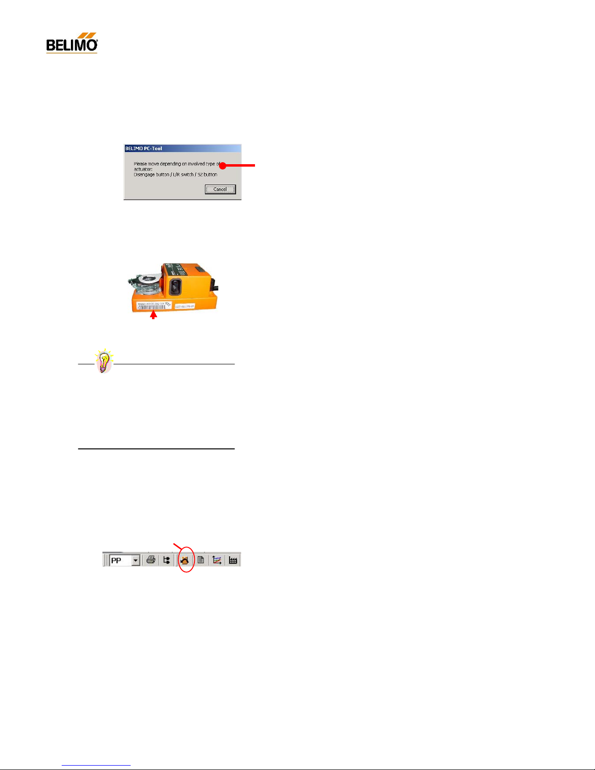
N-A4.2.3 Addressing by manual disengagement push-button
Procedure:
- Set the required address in the ‘MP address’ field.
- Activate ‘Manual addressing by acknowledgement’
- Press ‘OK’
- Press the manual disengagement push-button on the NMV-D2M. An
appropriate signal is given if the setting of the address is successful.
Repeat the procedure if a fault alarm is given.
N-A4.2.4 Addressing according to serial number
Procedure:
- Set the required address in the ‘MP address’ field.
- Activate ‘Addressing according to serial number’
- Enter the serial number (by hand or bar code reader)
When there is a direct link to the actuator the serial number read from
the NMV-D2M appears as the default value.
- Press ‘OK’
- An appropriate signal is given if the setting of the address is successful.
Repeat the procedure if a fault alarm is given.
N-A4.3 Reset to OEM setting <F5>
This f unction allows changed settings of operating volumetric flow to be
reset to the unit m anufacturer’s def ault values.
The following values are reset:
V’max
V’mid
V’min
Reset to OEM setting <F5>
Practical tip – Address stick er
Detach the large sticker and paste it on to the
appropriate installation plan.
This will allow addressing to be carried out
later with no need for direct access to the
controller. It also forms part of the installa
tion’ s
documentation.
Page 15
15
4A1PC-T V2.1 NMV-D2M-EN 11-02-04.doc PM VAV - Subject to technical changes
VAV – Module NMV-D2M
N-A5 Log Data display <F3>
Each read and write function is recorded in the NMV-D2M module in a
monthly log file. User actions and controller settings that have been executed from the appropriate PC can be displayed on the PC-Tool, and be
printed out if necessary, wit hout an acti ve connection to the NMV-D2M.
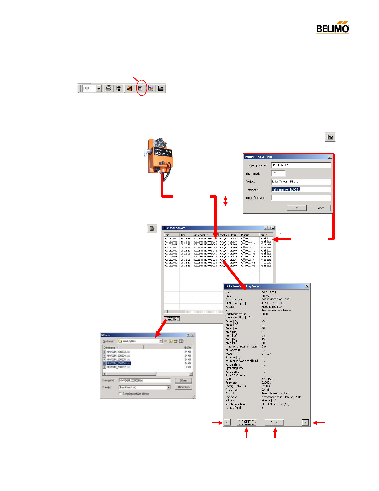
N-A5.1 Log data – Description of the elements
Log Data display <F3>
Access to previous
months
New entries
NMV-D2M
Print zoom
Project data form / <F4> /
Close zoom
Controller data
- Identification
- Setting
- Version ID
Read /
Write
Zoom d isplay
Log Data display / <F3> /
Project data
- Project
- File name
- Comment
Old entries
Page 16
16
4A1PC-T V2.1 NMV-D2M-EN 11-02-04.doc PM VAV - Subject to technical changes
VAV – Module NMV-D2M
N-A5.2 Log file
The log data is stored in a month file (text format) on the hard disk.
NA5.2.1 Procedure
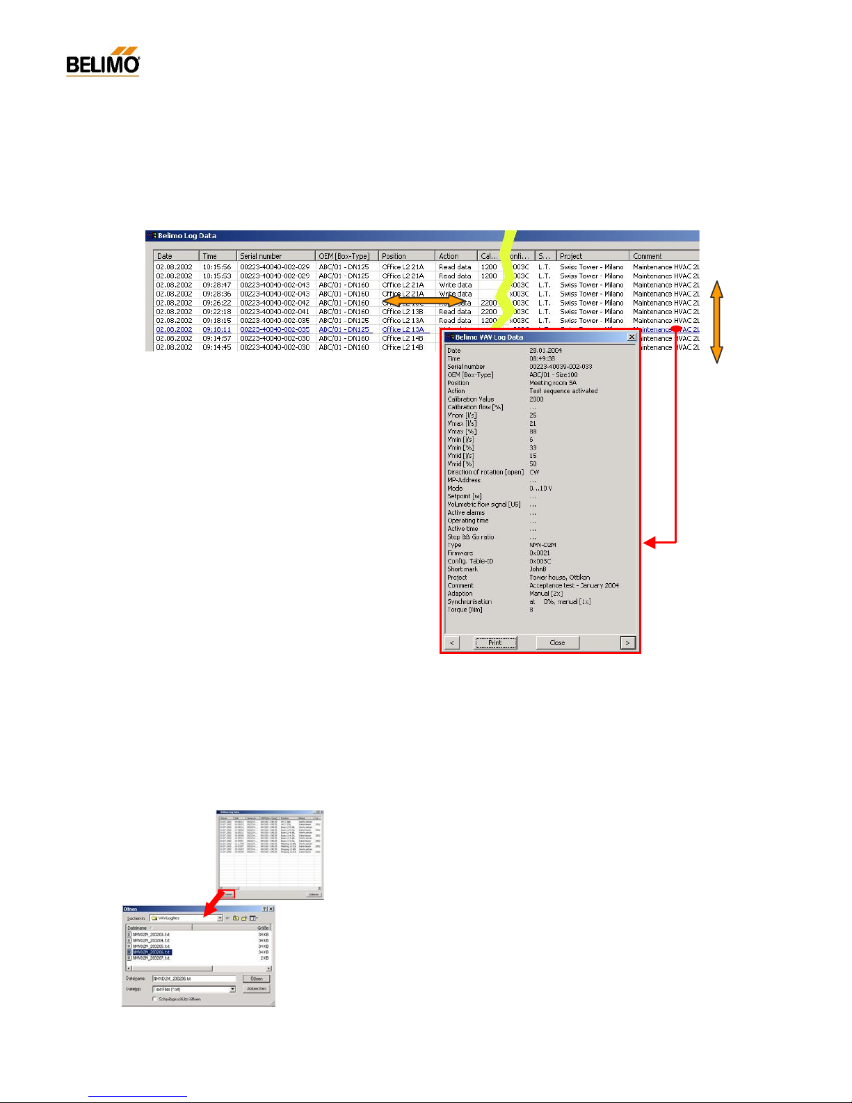
Data records are selected with the ‘Up’ and ‘Down’ ar row keys or the cursor. The ‘<-‘ and ‘->’ arrow keys or the cursor give access to any columns
that are outside the visible area of the screen.
Print: The data of a VAV-box equipped with an NMV-D2M can be printed
out directly from the display screen mask for documentation purposes.
Display screen mask (zoom function) - change entry:
- Mouse: Click on <’ or >’
- Keyboard: Use <TAB> to f ocus on ‘<’ and ‘>’ and t he n use the
<Space> key to page through the entries.
N-A5.2.2 Access to previous months
The data of previous months can be called directly from the Log Data
window. The function is selected with the ‘L og Data’ butto n.
Display old log file
Entries highlighted by clicking with the mouse or
with the arrow keys can be loaded into a display
screen mask (zoom function) by clicking on or
by pressing the <Space> key.
Page 17

17
4A1PC-T V2.1 NMV-D2M-EN 11-02-04.doc PM VAV - Subject to technical changes
VAV – Module NMV-D2M
N-A5.3 Fil e structure
The log file contains the following columns:
N-A5.3.1 File name
When a log file is generated it is given a unique name as follows:
- Structure: NMVD2M_JJJJMM.txt
e.g.: NMV-D2M_200206.txt for year 2002, month June
The struc ture of the name is fixed and cannot be changed by the user.
Column Description Explanation
Date Date log entry Time / Date, when ?
Time Time log entry "
Serial number Serial Number of NMV-D2M Identification, which ?
OEM [Box-Type] OEM information "
Position Plant designation "
Action Read / Write / Reset to OEM defaults User action, what ?
Calibration Value Calibration data For manufacturer only
Calibration flow [%] Calibration data For manufacturer only
V'nom [m³/h] Nominal flow Operating flow
V'max [m³/h] V’ma x sett ing "
V'max [%] " "
V'min [m³/h] V’m in s ett ing "
V'min [%] " "
V'mid [m³/h] V’m id s ett ing "
V'mid [%] " "
Direction of rotation [open]
Direction of damper rotation Actuator setting
MP-Address NMV-D2M address setting "
Mode Mode setting: 0...10 / 2...10 V "
Setpoint [w] “ variable setting, setpoint signal w "
Volumetric flow signal [U5]
“ variable setting, actual value signal U5 "
Active alarms Active alarms Alarm / Operating data
Operating time Operating time "
Active time Active time "
Stop && Go ratio Stop & Go ratio "
Result1 Parameter field Interna l parameters
Result2 " "
Result3 " "
Result4 " "
Result5 " "
Type NMV-D2M xxx [customised version] Controller type
Firmware SW version "
Config. Table-ID Configuration table "
Short mark Us er’s initials Project data <F4>
Project Project designation "
Comment Remarks "
Adaption Actuator Adaption behaviour Actuator setting
Synchronisation Actuator Synchronisation behav i o u r "
Torque [Nm] Actuator torque setting "
Column headings for log data window
The preset programming lan
guage governs the language
used for the column headings -
they are also used for
the displays in the log data window. Therefore, a new
language setting will only become effective for the log
data display when the next month file is generated.
Page 18

18
4A1PC-T V2.1 NMV-D2M-EN 11-02-04.doc PM VAV - Subject to technical changes
VAV – Module NMV-D2M
N-A5.3.2 Storage directory (path)
Default:
The subdirec tory in the PC-Tool program directory:
...\VAVLogfiles
User-defined path:
The user c an select the destination directory in the menu option
‘EXTRAS ¦ OPTIONS... ¦ NMVD2 M’
All log files are then stored in that directory.
N-A6 Trend Recall <F6>
The Trend function is provided so that the control parameters of a VAV- /
CAV-box equipped with a Belimo VAV-Compact NMV-D2M can be
checked.
An overall analysis of these values will show the system supply pressure,
the dynamic behaviour of the air box and the control system (e.g.: room
temperature controller, DDC, step control).
Using ‘Tre nd Rec all’ in the ‘Live T rend ’ f unc tion it is poss ible to read out
previously stored data from the data carrier and display it on the screen.
These functions are des cribed in detail in Part N-S Service:
See N-S4.2 ‘Live Trend’ and N -S4.4 ‘Trend Recall’
Trend Recall <F6>
Page 19
19
4A1PC-T V2.1 NMV-D2M-EN 11-02-04.doc PM VAV - Subject to technical changes
VAV – Module NMV-D2M
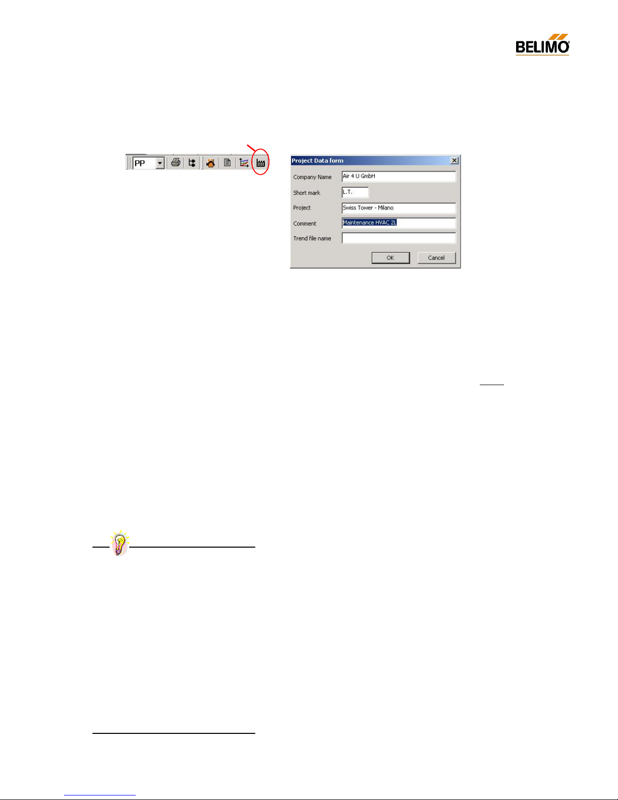
N-A7 Project Data form <F4>
This screen mask is used for entering project-specific and trend-specific
data such as file names. The data is used by the log, print, trend and test
functions.
N-A7.1 Data fields
- Company Company name, e.g. ‘Air 4 U GmbH’
Entered once.
- Initials Us er’s initials
these are only changed if there is more than one
person using the same PC.
- Project na me Usually entered once per visit to an installation, at
the start of work.
- Comment Entered when necessary before each trend and
test recording or jointly for a series of tests, for example.
- Trend file name When this function is being used an entry is made
in this field for each trend and test recording. If this
function is not being used a default name is used
instead.
N-A7.2 Procedure
Project data must be entered before execution of printout, trend re-
cording, etc.
The data given remains valid until it is changed or deleted.
When the entry screen mask is called the ‘Comment’ field is highlighted,
i.e. an entry can be made directly without having to select the field. This
is very helpful when carrying out series of tests.
Blank fields are permitted.
Project Data form <F4>
Practical tip – Project data for servicing
Start work: Press <F4>:
- Company / Initials / Enter project na me
Step 1:
Connect PC to NMV-D2M
Step 2:
a) Press <F4>, open input screen form
b) Enter remarks, e.g.:
‘Function test with new fan setting’
c) Close screen mask with ‘OK’
Step 3:
Start Live Trend or Test
Steps 2 and 3 must be repeated to repeat a
test or for the next VAV-box.
Page 20
20
4A1PC-T V2.1 NMV-D2M-EN 11-02-04.doc PM VAV - Subject to technical changes
VAV – Module NMV-D2M
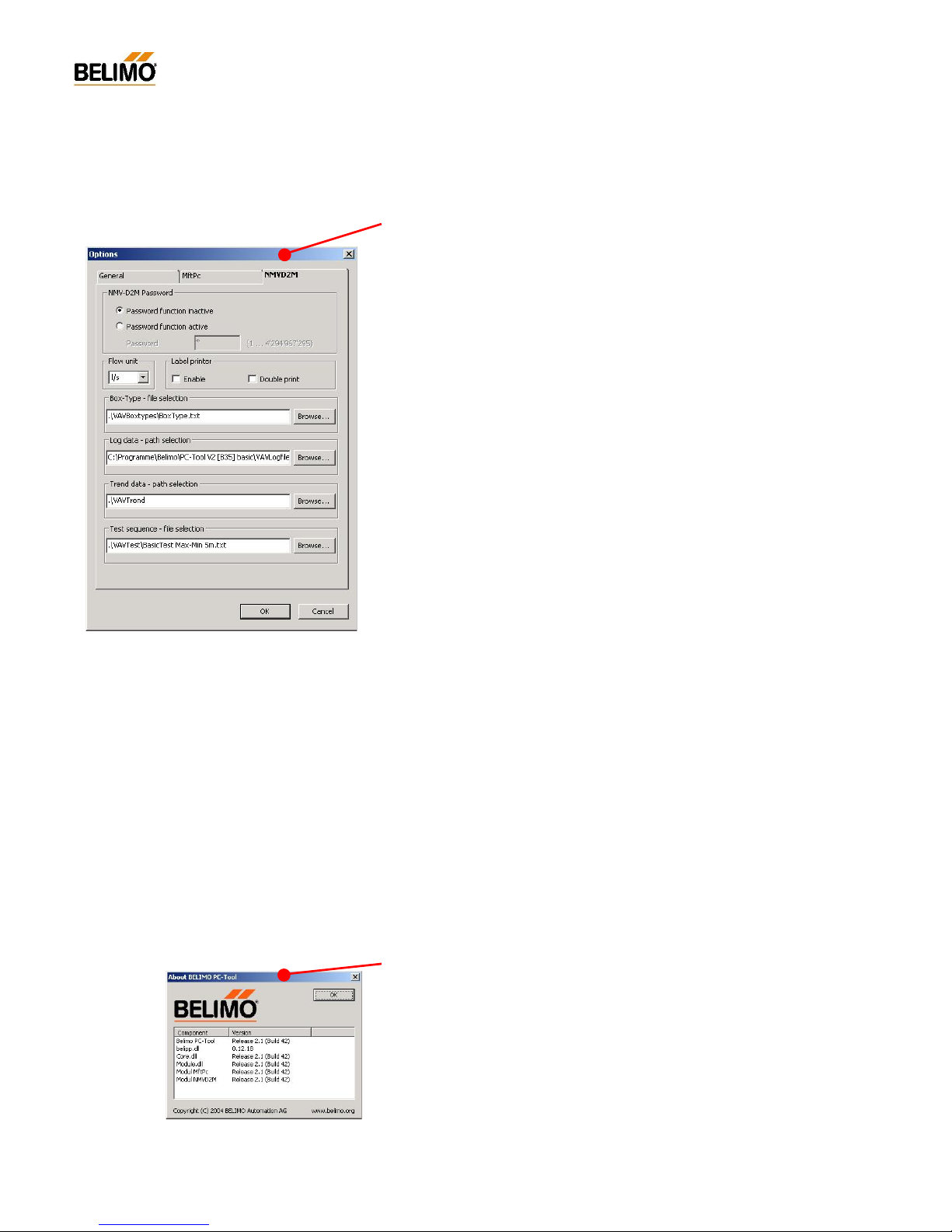
N-A8 Extras ¦ Options ¦ NMV-D2M
The ‘NMV-D2M’ options dialogue is used for defining specific parameters
for a VAV-Compact NMV-D2M controller.
N-A8.1 NMV-D2M password
NMV-D2M password function – only for manufacturers.
N-A8.1 Flow unit
Volumetric flow data is stored in the NMV-D2M in m
3
/h. The ‘Flow unit’
option allows the PC-Tool NMV-D2M Module display to be in m
3
/h, l/s,
cfm.
N-A8.2 Label printer
Label print option – only for manufacturers.
N-A8.3 Box-Type – File selection
Select Box-Type file – for manufacturer only.
N-A8.4 Log data - path selection
Destination d irectory for NMV-D2M log data. The NMV-D2M log files are
stored in the selected directory.
N-A8.5 Trend data - path selection
Destination directory for NMV-D2M ‘Trend’ and ‘Test’ data. All NMV-D2M
*.tnd files are stored in the selected directory.
N-A8.6 Test-Sequence – File selection
Defining the Test-Sequenc es activated in the ‘Service’ register with the
‘Test‘ function.
N-A9 Help
Specif ic parameters for use with VAV-Compact NMV-D2M controllers are
defined in the ‘NMV-D2M’ options dialogue.
N-A9.1 Help entries (BelimoPcToolHelp_English.pdf)
Call this user documentation in pdf format.
In order to display this file the Adobe Acrobat® Reader program must be
installed first.
The help entries cover all the PC-Tool Modules that are currently available.
N-A8.1 About Belimo PC-Tool
This option provides information on what PC-Tool components are installed and their versions.
Page 21
21
4A1PC-T V2.1 NMV-D2M-EN 11-02-04.doc PM VAV - Subject to technical changes
VAV – Module NMV-D2M
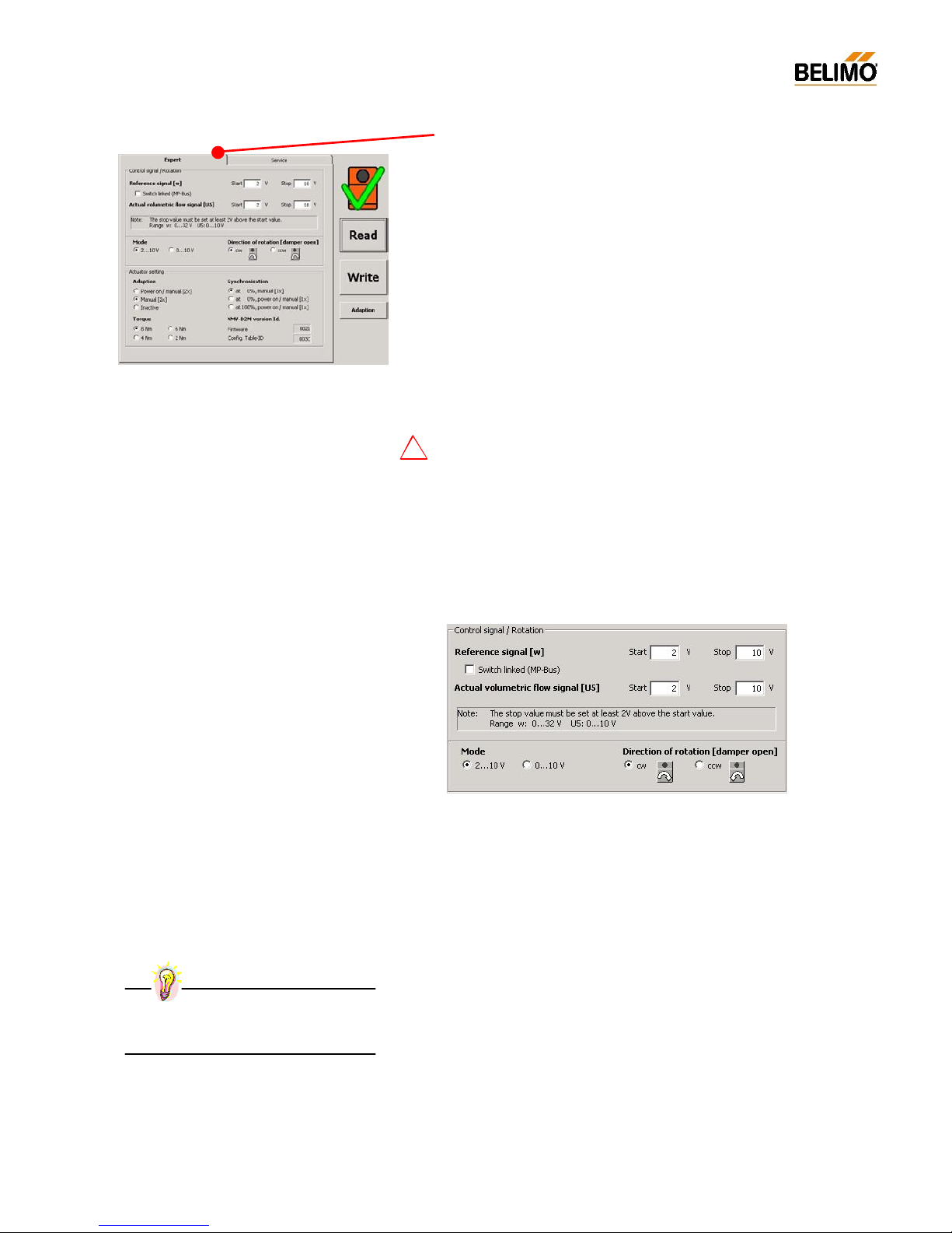
N-E Expert
The ‘Expert’ register allows the manufacturer and experienced service
engineers to make changes to specific NMV-D2M settings such as:
Control signal
Mode / Direction of rotation
Adaption and synchronisation characteristics
Display of NMV-D2M version data
N-E1 Using the ‘Expert‘ register
The parameters contained in the ‘Expert’ register are the ones originally
set during installation of the equipment. These settings are made by the
manufacturer of the air boxes who also bears overall responsibility for
their proper functioning. Any incorrect changes made to these parameters
might cause the equipment to malfunction!
For this reason an appropriate message appears when changing from
‘Servic e’ to ‘Expert’.
N-E2 Control Signal / Direction of rotation
N-E2.1 Control signal
Variable settings for referenc e signal [w] and actual volumetric flow signal
[U5].
See 4. NMV-D2M Product Information for more information on connections.
!
Practical tip – Mode setting
Make the 0 ... 10 / 2 ... 10 V setting directly
from the ‘Mode’ field.
Page 22
22
4A1PC-T V2.1 NMV-D2M-EN 11-02-04.doc PM VAV - Subject to technical changes
VAV – Module NMV-D2M
Practical tip – Quick setting
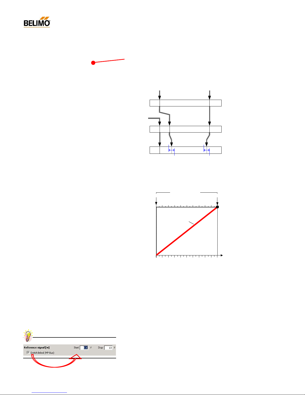
N-E2.1.1 Reference signal [w], Working range V’min ... V’max
Start point: DC 0.6 ... 30 V
Stop po int: DC 2.6 ... 32 V
Range:
N-E2.1.2 Actual volumetric flow signal [U5]
Actual volumetric flow signal [U5], Working range 0...100% V’nom
Start point: DC 0.0 ... 8 V
Stop po int: DC 2.0 ... 10 V
Range:
N-E2.1.3 Sensor connection
In bus mode (‘MP’ address 1...8) an active sensor or a switch can be
connected to the NMV-D2M reference input [w]. This input value can be
used in the higher level control system for VAV control, e.g. room temperature or other applic ations. See 4. NMV-D2M Product Information for
further information.
- Connecting switches
In order to allow the NMV-D2M to evaluate the status of a connected
switch reliably the start point of the working range must be properly set
first:
Start point: DC 0.6 V It is essential for the Start Point to be
set to 0.6 V
Stop po int: DC 10 V
Reference signal function [w]
in the V’min ... V’max control range
for controlling the NMV-
D2M in CAV and VAV
applications
its signal form can be adapted by the mode or
variable setting
Actual volumetric flow signal [U5]
corresponds to 0...100% V’nom
indicates the current actual value of volumetric flow
is not affected by the V’min and V’max settings
its signal form can be adapted by the mode or
variable setting
0 10020 40 60 80
Volumetric flow
[%V'nom]
V'nom
Actual volumetric
flow signal U5 [V]
Start point Stop point
Mode:
- 0...10V
- 2...10V
- variable
Actual volumetric
flow signal U5
V'min V'max< modulating function >
0,0 0,5 10
0...10V
Shut-off
V'min
close
V'max< modulating function >
0,0 0,1 102,0
2...10V
V'min
close
V'max
< modulating function >
30,0 32,0
2,60,6
0,0 0,1
variable
Start point Stop point
Mode:
Page 23
23
4A1PC-T V2.1 NMV-D2M-EN 11-02-04.doc PM VAV - Subject to technical changes
VAV – Module NMV-D2M
- Connecting active sensors
Start point: DC 0.0 V The range of adjustment corresponding
to the working range of the sensor.
Stop po int: DC 10...32 V
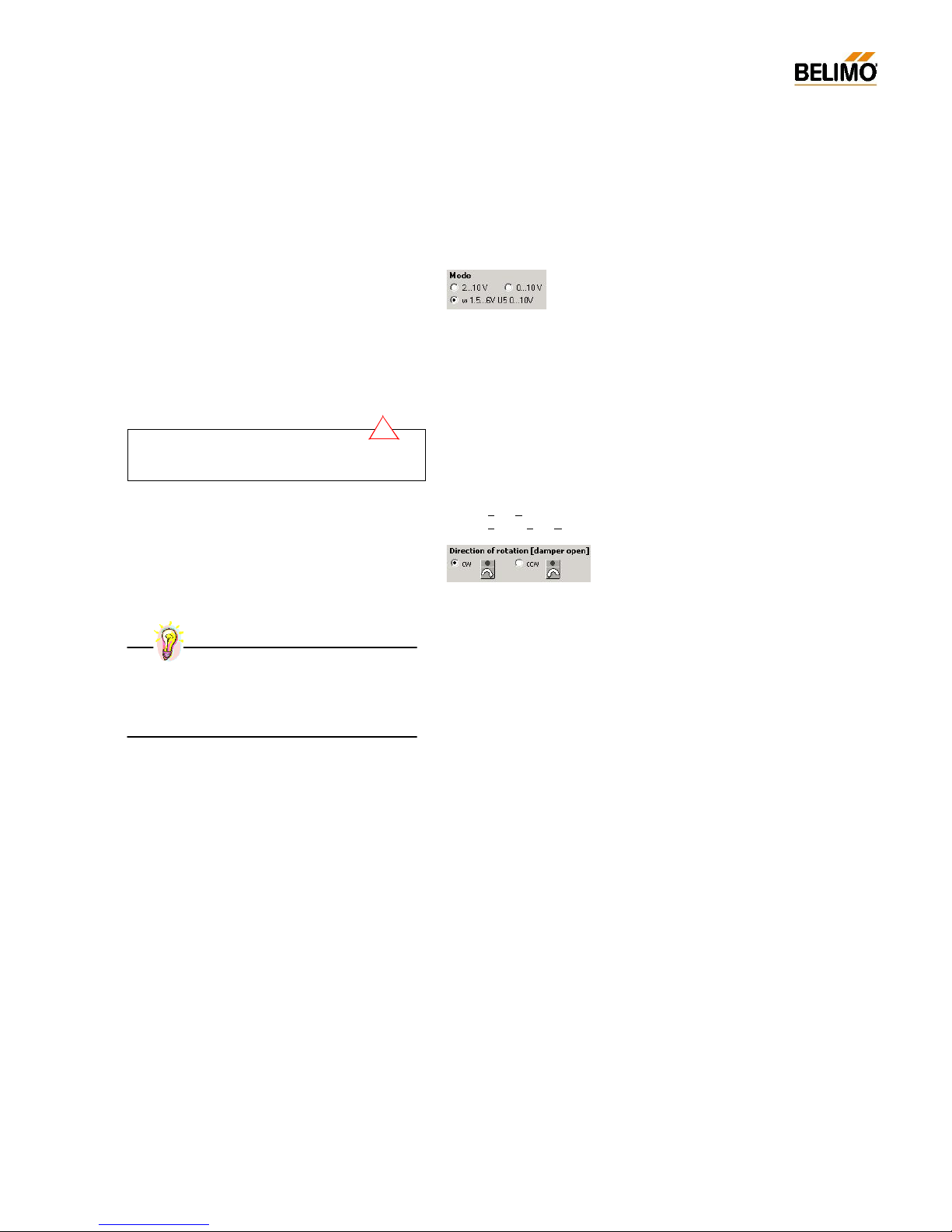
N-E2.2 Mode
2 ... 10 / 0 ... 10 V / variable
Variable settings are displayed in this field or can be reset by 2 ... 10 / 0 ...
10 V settings. Variable settings are made in the field above.
See 4. NMV-D2M Product Information for further information.
N-E2.3 Direction of rotation, damper opening
Depending on the design of the air b o x the manufacturer sets the direction of rotation of the damper accordingly. The direction of rotation depends on the open position of the damper.
Setting:
cw clockwise (looking on the damp er spindle)
ccw c
ounterclockwise (looking on the damper spindle)
Direction of rotation
An incorrect direction of rotation setting will cause the
air box to malfunction.
!
Practical tip – Damp er open
Shortage of air due, for example, to excessively low
supply pressure / fan fault: The VAV unit damper is
100% open and stays so while Setpoint > Actual value
Page 24
24
4A1PC-T V2.1 NMV-D2M-EN 11-02-04.doc PM VAV - Subject to technical changes
VAV – Module NMV-D2M
N-E3 Actuator settings
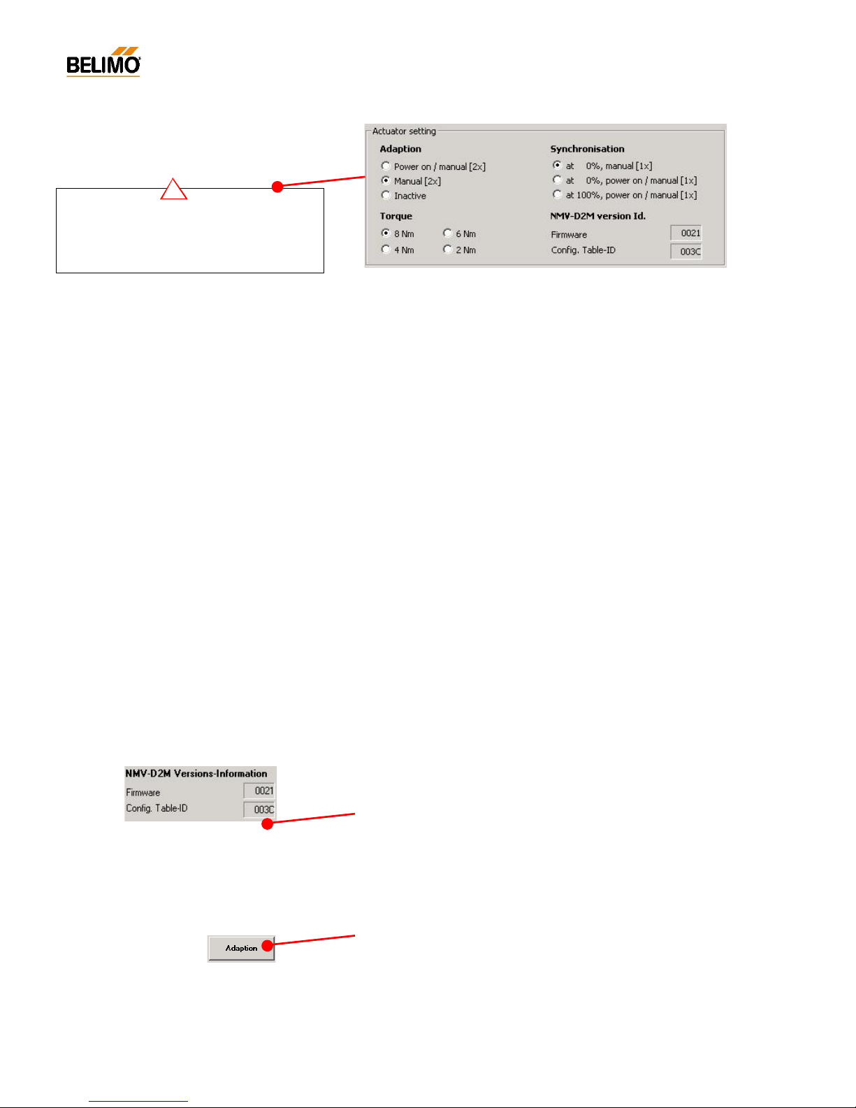
N-E3.1 Adaption
For adapting the control characteristics to the available rang e of control.
Setting Function Remarks
Manual (2x) Adaption is initiated by Recommended
2x press manual disengagement button setting
Off Adaption deactivated
Automatic Adaption initiated:
(Power ON - after each power off
and manual (2x)) - 2x p ress manual d i sengag e ment bu tto n
N-E3.2 Synchronisation
Initiation criteria for synchronising the position calculation.
Setting Function Remarks
at 0% manual (1x) Synchronising at Closed position Recommended
- at first commissioning setting
- when manual disengagement butto n
at 0% manual (1x) Synchronising at Closed position
and Power ON - at each power-up
- at power fail
- when manual disengagement button
at 100% manual (1x) Synchronising at Open position
and Power ON - at each power-up
- at power fail
- when manual disengagement butto n i s pressed
N-E3.4 Torque
Adapting the maximum value of torque to suit the type of air box being
used.
Step Function Torque
100% Rated active torque min. 8 Nm
75% 75% of active torque ca. 6 Nm
50% 50% of active torque ca. 4 Nm
25% 25% of active torque ca. 2 Nm
N-E3.5 NMV-D2M versions information
Indication of the version of software and the configuration table currently
being used in the controller.
- Firmware : Software version (Hex-Code)
- Config. Table ID : Configuration table (Hex-Code)
N-E4 Adaption
With this function it is possible to acquire the positions of the upper and
lower damper end-stops and store them in the NMV-D2M. Running time
and working range are then adapted to the available angle of rotation. Ascertaining the positions of the mechanical end-stops allows a smooth approach to the end-stops so preventing any unnecessary overloading of
the actuator and damper mechanisms.
Actuator setting
An incorrect actuator setting can cause the air box to
malfunction or even to be damaged.
For this reason the se
ttings should only be changed
after prior consultation with the manufacturer.
!
Support enquiries – Versions information
The versions data is stored in the log file by the log
function each time information is read. It c
an be
display ed with the ‘Read log data’ func tion <F3>.
This information should always be given in re
sponse
to an enquiry.
Adaption behaviour
The adap
tion behaviour can be adjusted to suit
particular applications, see N-E3.1
Page 25
25
4A1PC-T V2.1 NMV-D2M-EN 11-02-04.doc PM VAV - Subject to technical changes
VAV – Module NMV-D2M
N-S Service
The ‘Service’ register is provided for:
Adjusting the operating value of volumetric flow
Reading the NMV-D2M operating data
Testing the control and operating functions
All relevant parameters of a VAV- / CAV-box equipped with a Belimo
VAV-Compact NMV-D2M are displaye d on a screen. T he ‘Operation’ field
and the operating options associated with it allow a wide range of test and
monitoring functions to be employed .
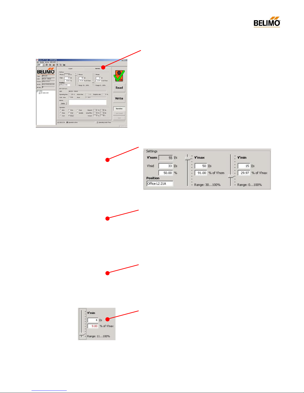
N-S1 Settings
N-S1.1 V’nom
The nominal setting of volumetric f low allows t he NMV-D2M to be
adapted to the particular VAV- / CAV-box being used. The size, nominal
flow rate and operating parameters are taken into account and preset.
V’nom is the highest possible volumetric flow that the air box is capable of
when the pressure drop and noise level are within the maximum permitted
operating conditions.
N-S1.2 Adjusting the operating value of volumetric flow
- V’max
V’max is the upper limit value depending on the nominal value of volumetric flow.
Range of adjustment: 30...100% V’nom.
- V’min
V’min is the lower limit value depending on the maximum value of volumetric flow.
Range of adjustment: 0 ...100% V’max
Range of control: x
*)
…100% V’max
*) Note:
refer to section N-S1.2 .1…
- V’mid
For constant-volume applications (CAV) there is an intermediate position
available (V’mid) for finer g rading of the se ttings.
Range of adjustment 0...100% of V’min...V’max range.
Nominal value of volumetric flow [V’nom]
Energy and noise considerations lead to the setting
of an utmost permitted value of specifi
c volumetric
flow for each diameter of duct. The binding value of
nominal volumetric flow is defined by the manufa
c-
turer of the air box who also bears responsibility for
the proper functioning of his VAV boxes.
Operating value of volumetric flow
The linear characteristic of the NMV-D2M volume
t-
ric flow controller allows easy setting of the opera
t-
ing values of volumetric flow rate for installatio ns.
Th e V ’m ax / V’min setting pro
cedure is normally
carried out by the manufac
turer of the air box or
alternatively during commissioning.
Reset to OEM setting <F5>
This function allows changed settings of operat
ing
flow V’max / V’mid / V’min to be re
stored to the
man ufactur er’ s basic se tti ngs .
Page 26
26
4A1PC-T V2.1 NMV-D2M-EN 11-02-04.doc PM VAV - Subject to technical changes
VAV – Module NMV-D2M
N-S1.2.1 Control range
The control of volumetric flow of a CAV/VAV box is based upon the differential pressure measuring picked up at its baffle device. This requires a
minimal differential of approx. 2…5 Pa independently of the VAV box type
or its manufacturer. This due to the fact that that the minimal limitation is a
physical limitation given by the entire control equipment (design and mechanical construction, pick-up device and the differential pressure measurement). The proper control of a VAV control loop can not be achieved
below that border.
The Belimo VAV controller NMV -D2M has an incorporated feature c alled
‘creep flow suppression’ which suppresses the differential-pressure signals around zero. The limiting is able to prevent undefined movements of
the actuator within the pressure range below 2 Pa until the setpoint requires an volumetric flow above that area.
The smallest useable volumetric flow setting withi n the control range of a
VAV box get influenced by the V’nom – V’max ratio. The smaller the
V’max setting the bigger gets the influence of the physical control limita-
tion to the usable control range width.
Below you’ll find a chart showing the dependencies and influences.
The example shows a Belimo VAV compact controller NMV-D2M (with 2
Pa creep flow suppression) with different V’Max settings:
Adjustment
Case 1 Case 2 Case 3 Case 4
V’no m
660 m3/h
V’m ax s etting 660 m3/h 500 m3/h 300 m3/h 200 m3/h
smallest controllable volu-
metric flow (equals ~2 Pa)
~60 m3/h
usable Control range
(box depending)
x...100% V’nom
9...100%
usable Control range 60...660 m3/h 60...500 m3/h 60...300 m3/h 60...200 m3/h
resulting smallest V’min
setting (equals ~2 Pa)
(in % of V’max)
9% 12% 20% 30%
conclusion .
good good over sized over sized
Note: the values of the chart are VAV box specific values, they might differ for other boxes!
As a rule, an oversized VAV-Box has a smaller control range than a correct sized one.
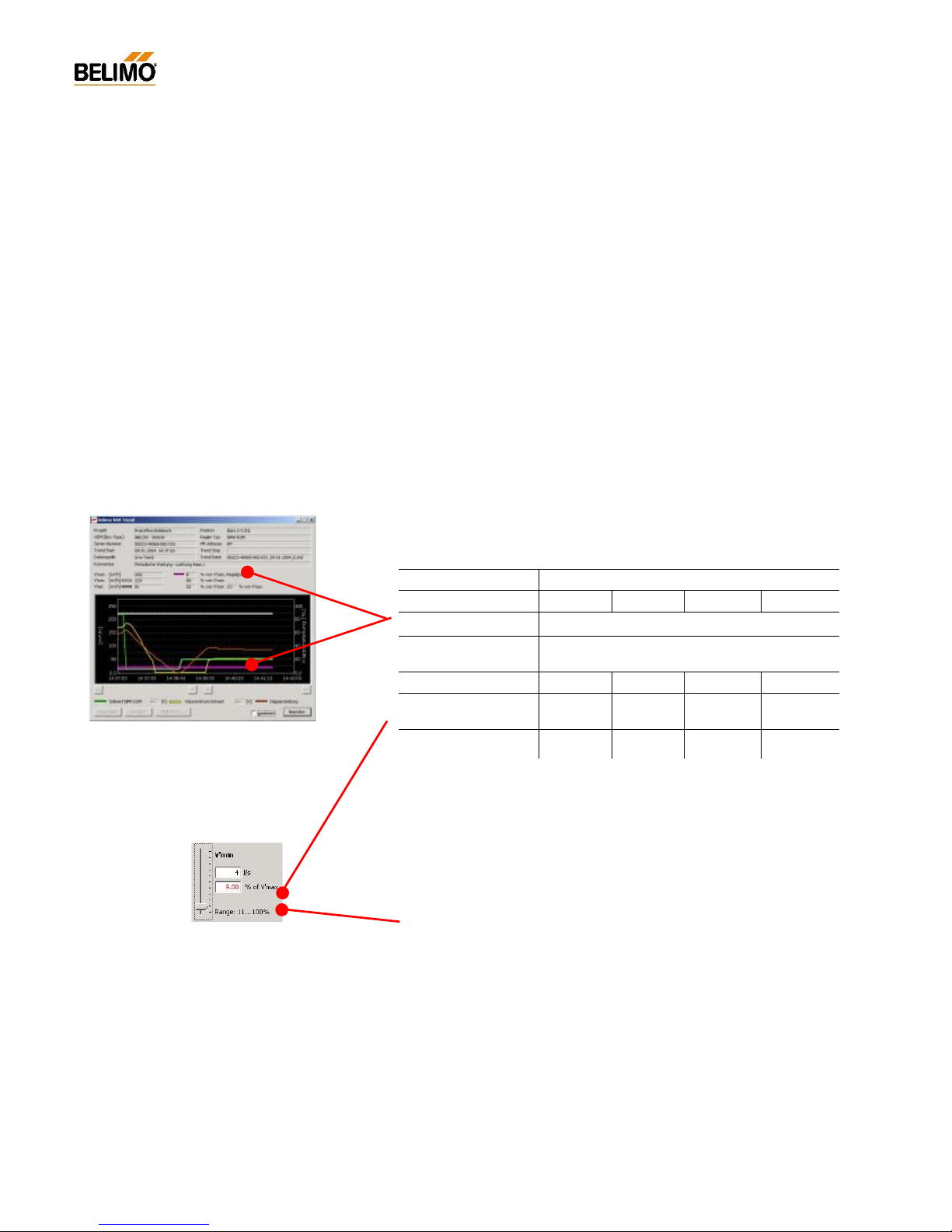
- V’min setting below the usable control range
A V’min settings below the usable control range can be adjusted for certain applications e.g. box requires shut-off position. To inform the user
that he is using a difficult setting, the value in the ‘% of V’max’ field
changes its colour to red.
Display in tab ‚Serv ice ’
Display in ‚Trend View’
Page 27
27
4A1PC-T V2.1 NMV-D2M-EN 11-02-04.doc PM VAV - Subject to technical changes
VAV – Module NMV-D2M
N-S1.3 Position [16-character text field]
Input field for a specific plant designation string:
e.g. f ield address, plant designation, diagram position.
N-S2 NMV-D2M information
N-S2.1 OEM
OEM-specific information string:
e.g. firm’s name, air box type, installation, order
N-S2.2 Operating time
Number of hours that the NMV-D2M has been powered up.
N-S2.3 Active time
Number of hours that the NMV-D2M has been powered up and performing mechanical movements.
N-S2.4 Stop&Go ratio
Ratio of active time to operating time
(calculation = active time h / operating time h x 100)
If the Stop&Go ratio is relatively high an unstable reference signal is a
possible cause.
N-S2.5 Calibration value
A setting for a specific air box that the manufacturer of the unit has ascertained during his calibration run on the test rig. The calibration value is an
internal controller variable that represents the differential pressure at
V’nom.
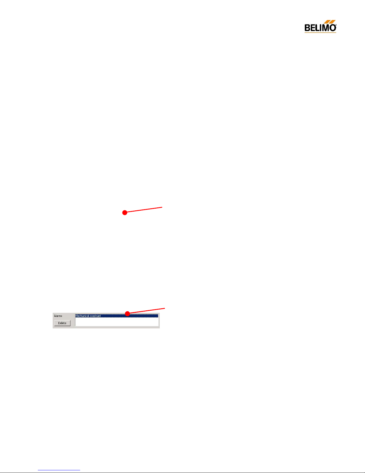
N-S2.6 Alarms
This field displays the alarm signals generated by the NMV-D2M:
Stop&Go ratio too high
Excessive travel (10%)
Mechanical overload
The alarms can be cancelled by clicking on a particular alarm and pressing the ‘Delete’ key.
Calibration value
The nominal value of volumetric flow and the
corresponding calibration value are determined and set solely by the manu
facturer of
the air box (OEM). The manu
facturer bears
responsibi
lity for the proper functioning of his
VAV boxes.
Page 28
28
4A1PC-T V2.1 NMV-D2M-EN 11-02-04.doc PM VAV - Subject to technical changes
VAV – Module NMV-D2M
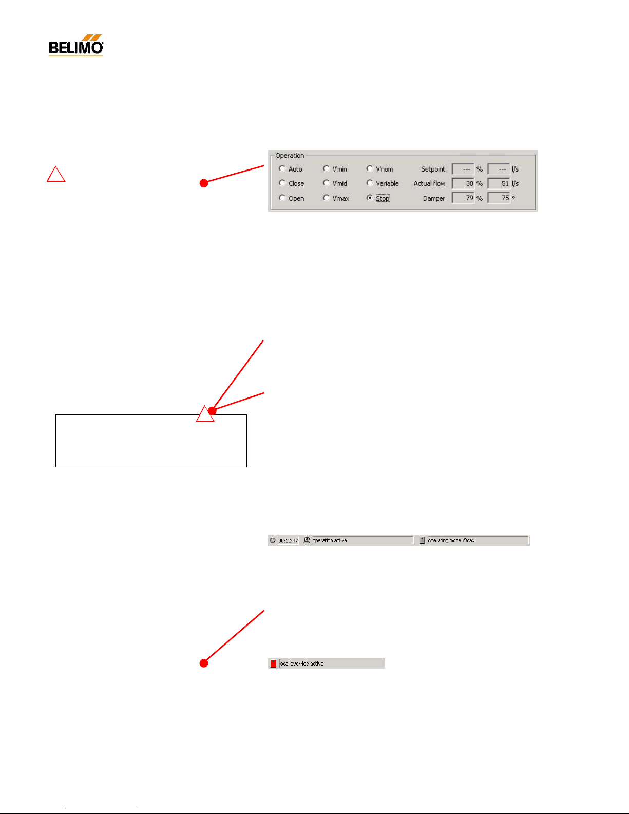
N-S3 Operation
Auto – in control mode
Under nor mal ci rc umstanc es th e ‘Au to’ mode is acti ve. In thi s si tua tion the V AV /
CAV controller is controlled via the reference input [w] or, in bus mode, via setpoint
issue.
The ‘Operation’ field is for checking the control functions either on-site or
on the manufacturer’s test rig.
N-S3.1 Enable ‘OPERATION’
Pressing this button e nables or disables operating step control of the
NMV-D2M.
The ‘OPERATION’ button is disabled when ‘LIVE TREND’ or ‘TEST’ are
active.
N-S3.2 Disable ‘OPERATION’
The preset operating step must be disabled after the ‘Operation’ function
has been used!
If – during active operating step control – the communication conductor
between the PC-Tool and the VAV controller suffers open-circuit, the preset operating step will remain stored in the NMV-D2M.
Reset (power-down) will return the NMV-D2M to Auto mode.
N-S3.3 Status infor mation
Status line when ‘Operation’ is active:
- PC status: ‘Operation’ active
- NMV-D2M status : the preset operating step
N-S3.4 Local override control
In order to ensure active local override control these local commands are
given a higher priority.
e.g.: CAV air box with ‘Close’ override control.
Active local override control – when the NMV-D2M module is also iss uing
an operating step – is indicated by means of a red square symbol:
!
Note – Disable operation
Before communication with the NMV-D2M is interrupted the active mode of operation must be dis-
continued by disabling the ‘OPERATION’ function !
!
Override control / Operating steps
By appropriate connection of the reference input [w]
of the NMV-
D2M it is possible to select different
modes of operation.
See 4. NMV-D2M Product Information
Auto – with the Tool connected
- Conventional mo de: In this situation the VAV /
CAV controller is controlled via the reference input
[w].
- Bus mode: When there is active communication with an operating device, setpoint issue from
the higher level system (e.g. UK24LON) is interrupted. Without direct setpoint issue from the Tool
the NMV-D2M is controlled from the reference
input [w] (0 V = V’min or, with a sensor connection,
according to the sensor value, 0...10 V).
Page 29

29
4A1PC-T V2.1 NMV-D2M-EN 11-02-04.doc PM VAV - Subject to technical changes
VAV – Module NMV-D2M
N-S3.5 Operating steps
- Auto – Status: ‘Auto [ref erence signal w]’
Classic application: the NMV-D2M regulates to the applied 0/2...10 V
reference signal
Bus mode: NMV-D2M controls the adjusted V’min value. Note: In case
an additional sensor is connected (Bus mode only), the NMV-D2M follows
to the 0...10 V voltage value of the sensor input [w].
- Close – Status: ‘Damper closing’
Damper moving to the Closed position.
Setpoint display: --
- Open – Status: ‘Damper opening’
Damper moving to the Open position.
Setpoint display: --Actual value display: range 0...110% V’nom
- V’min – Status: ‘Operating step V’min active’
The NMV-D2M regulates the volume to the preset V’min value.
- V’mid – Status: ‘Operating step V’mid active’
The NMV-D2M regulates the volume to the preset V’mid value.
- V’max – Status: ‘Op erating s tep V’max ac tive’
The NMV-D2M regulates the volume to the preset V’max value.
- V’nom – Status: ‘NMV-D2M regulating to V’nom’
The NMV-D2M regulates the volume to the preset V’nom value.
- Variable – Status: ‘Variable operation V’min…V’max’
Issue of the setpoint for volumetric flow, as an absolute
value (e.g. in m
3
/h) or as a relative value (in %).
Range: operating volumetric flow setting V’min...V’max.
- Stop – Status: ‘Moto r s top’
- Motor gets stopped (freezed’ at the actual position
- Actual flow gets displayed
N-S3.6 Reference / Actual value of damper position
Reference value: preset setpoint for volumetric flow
Setpoint display as [%] value and as absolute value in [e.g.: m
3
/h]
*)
The two fields serve as the input field when the ‘Variable’ mode of operation is active.
Actual value: current actual value of volumetric flow
Actual value display as [%] value and as absolute value in [e.g.: m3/h]
*)
Range: 0...110% V’nom
Damper position: actual position of the damper
Damper position display as [%] value and as absolute value in [°]
**)
*)
For absolute value display the V’nom value mus t be entered. The value is entered by the
manufacturer of the VAV / CAV box during the calibration procedure.
**)
After a successful adaption run the 0...100% display is replaced by the available damper control range.
Absolute display in degrees of angle (0...95°)
V'nom
V'mid
VAV / CAV operation
Close
[depends on
supply pressure]
V'max
Open
V'min
Vol umetric
flow [V'nom]
0 10010 20 30 40 50 60 70 80 90
Page 30
30
4A1PC-T V2.1 NMV-D2M-EN 11-02-04.doc PM VAV - Subject to technical changes
VAV – Module NMV-D2M
N-S4 Trend
The Trend function has been provided so that the control parameters of
VAV / CAV-boxes equipped with a Belimo VAV-Compact NMV-D2M c an
be checked. A full analysis of these values provides information on the
system supply pressure and the dynamic behaviour of the air box and its
control system (e.g.: room temperature controller, DDC, step control).
There are two methods available: ‘Live Trend’ and ‘Trend Recall’. In the
case of the former the data is recorded ‘live’ and presented as a diagram
on the screen in real time. With the latter, data that has been recorded
previously is read from the data carrier and displayed on the screen.
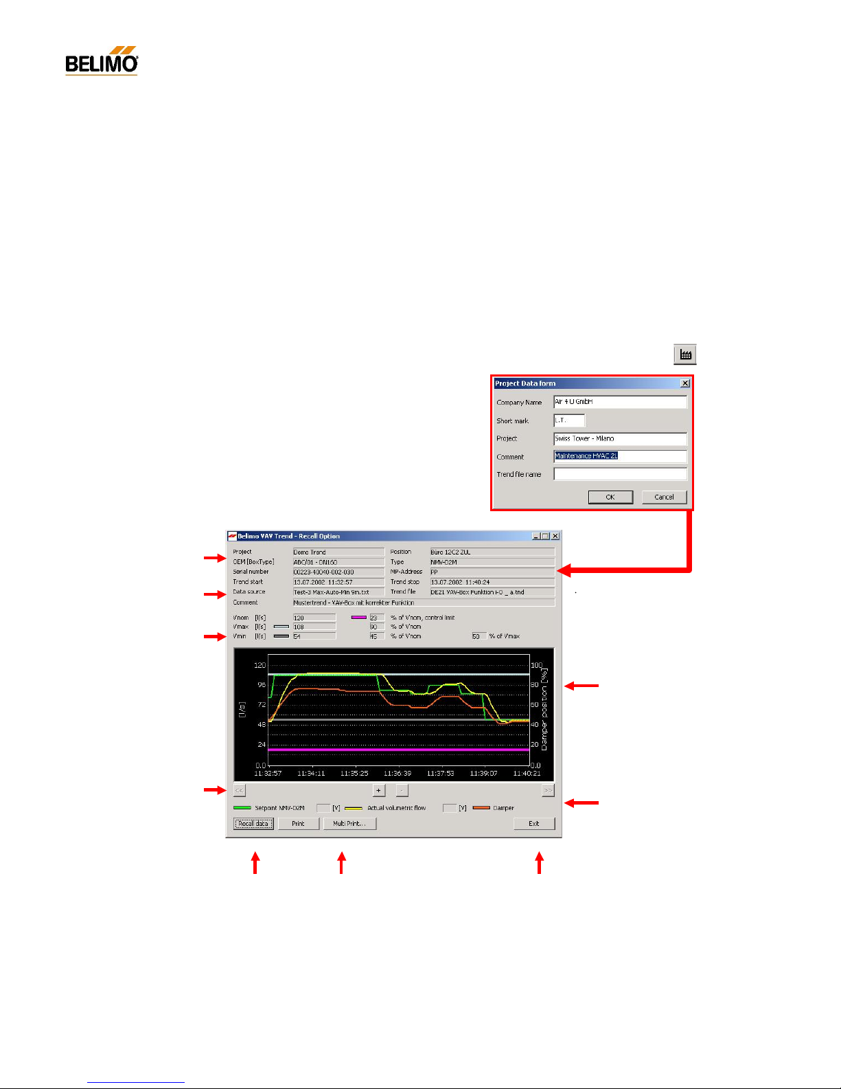
N-S4.1 Trend – Description of the elements
Project &
controller data
Operating values
of volumetric flow
rate
V’nom -
V’max -
V’min -
Control limit -
Start-
Stop
Data source
Trend data
- V’nom
- V’min / V’max
- Setpoint / Actua l value
- Damper position
- Control limit
Legend
with voltmeter function
Fwd / Back
display + / -
Trend Recall
Print options
Project Data form / <F4> /
Abort
Project data
- Project
- File name
- Comments
Project Data form <F4>
This allows the project-specific and trendspecific data, such as file names, to be entered.
The data is used by the log, print, trend and
test functions. T he data entries remain v alid
until they are changed or deleted.
-> Blank fields are allowed
Page 31
31
4A1PC-T V2.1 NMV-D2M-EN 11-02-04.doc PM VAV - Subject to technical changes
VAV – Module NMV-D2M
N-S4.2 Live trend
The ‘LIVE TREND’ function requires an active communication link to the
NMV-D2M controller. This function allows a VAV controller to be checked
under real operating conditions or a setpoint of volumetric flow to be issued, both options showing the active control behaviour of the VAV /
CAV-box to which it is connected.
N-S4.2.1 Start/Stop
Start: with the ‘LI VE TREND’ b utton
Stop: - with the ‘LIVE TREND’ or ‘STOP’ buttons
- with the <ESC> key
- by leaving the ‘Service’ register
- by interrupting communication
- by local initiation of synchronising or adaption
‘Live Trend’ cannot be started when ‘OPERATION’ is activated.
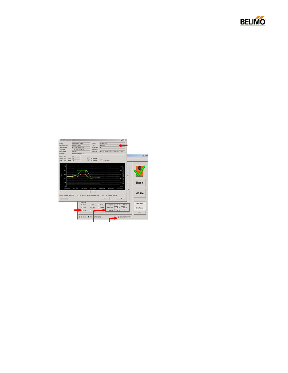
N-S4.2.2 Selecting the operating step
Simultaneous display of the two windows allows the volumetric flow rate
to be changed while a trend is being recorded so that the resulting system
response can be observed.
N-S4.2.3 Voltage readings in ‘Live Trend’
The voltage readings for ‘Setpoint NMV-D2M’ and ‘Actual value of volu-
metric flow’ are only available when the ‘Auto’ mode is active and the
NMV-D2M address setting is ‘PP’.
The solution:
- Reference value NMV-D2M V’min...V’max
- Actual volumetric flow 0...100% V’nom
Note – Voltage display:
The voltage readings shown are values deter
mined
by calculation. When dealing with faults the readings should be veri
fied with a suitable mea suring
instru ment.
While the NMV-D2M is communicating with the PC-
Tool the actual value signal U5 measured with a
voltmeter at the NMV-D2M does not correspon
d to
the actual value of volumetric flow !
‘Live Trend’
Operating step
Actual values NMV-D2M status
Page 32

32
4A1PC-T V2.1 NMV-D2M-EN 11-02-04.doc PM VAV - Subject to technical changes
VAV – Module NMV-D2M
N-S4.2.4 Trend file
For each new action the ‘Live Trend’ function generates a text file with a
unique name.
- File name
Default:
- structure: serial number_date_index.tnd
e.g.: 00151-10002-002-029_11.06.2002_e.tnd
User-defined file name:
Enter the trend file name in the ‘Project Data form’ dialogue box.
- structure: 15characters _date_index.tnd
e.g.: Fkt-Prüf-G23-T_04.11.2001_g.tnd
- Storage directory (path)
Default:
As a subdirectory of the PC-Tool program directory:
...\VAVTrend
User-defined path:
The user can select the destination directory in the ‘EXTRAS ¦ OPTIONS... ¦ NMV-D2M’ menu. All trend files are then stored in that direc-
tory.
Project Data form <F4>
This allows the project-specific and trendspecific data, such as file names, to be entered.
The data is used by the log, print, trend and
test functions. T he data entries remain v alid
until they are changed or deleted.
-> Blank fields are allowed
Practical tip – File clearing
If the trend function is used ofte n a large
number of trend files will be accumulated.
Therefore, after plotting, it is advisable to:
- transfer the data to a project directory
- delete the data if it is no long er needed
Page 33
33
4A1PC-T V2.1 NMV-D2M-EN 11-02-04.doc PM VAV - Subject to technical changes
VAV – Module NMV-D2M
N-S4.3 Trend Re call <F6>
Previo usly s tored data is read from the hard disk and displayed on the
screen.
N-S4.3.1 Read Trend file
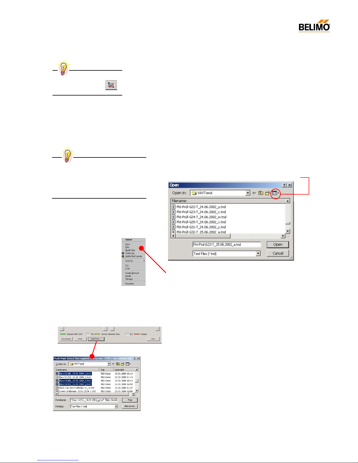
The Trend window is opened from the ‘NMV-D2M ¦ Trend Recall’ menu
<F6> or the toolbar. The ‘READ DATA’ button opens a browse window
with access to all available drives.
Default path:
as s et under ’EXTRAS ¦ OPTIONS ¦ NMV-D2M’.
The browser window is used in the same way as the Explorer application
of the PC operating system.
Hints:
- this function allows lists, detail displays, etc.
- highlight the required trend file and right clicking on it will open a list with
available options:
Print Trend data
Two options can be used::
- Print Print actual Trend file
- Multi Print... selection and print of several f iles
How does multi selection work
- click at the requested file while pressing the <Ctrl> button
- activate ‘Print’
.
‘Trend Recall’
start from toolbar:
Practical tip – File clearing
If the trend function is used of
ten a large
number of trend files will be accumulated.
Therefore, after plotting, it is advisable to:
- transfer the data to a project directory
- delete the data if it is no long er needed
The appropriate file might now
be deleted, renamed, etc. as
required. Direct copying to
floppy disk or transmission by
e-mail are very simple procedures
Page 34
34
4A1PC-T V2.1 NMV-D2M-EN 11-02-04.doc PM VAV - Subject to technical changes
VAV – Module NMV-D2M
N-S5 Test
The ‘TEST’ function allows structured testing of the VAV- / CAV-box to be
carried out.
When the function is started it first checks the system supply pressure
and then runs to a defined typical value of volumetric flow with the help of
a preselected Test-Sequence. The Trend window is opened so that the
test results can be checked and stored.
For the purpose of carrying out reviews, the Test-Sequence recorded
from the installation can be read from the hard disk, displayed on the
screen and printed out.
N-S5.1 Test-Sequence
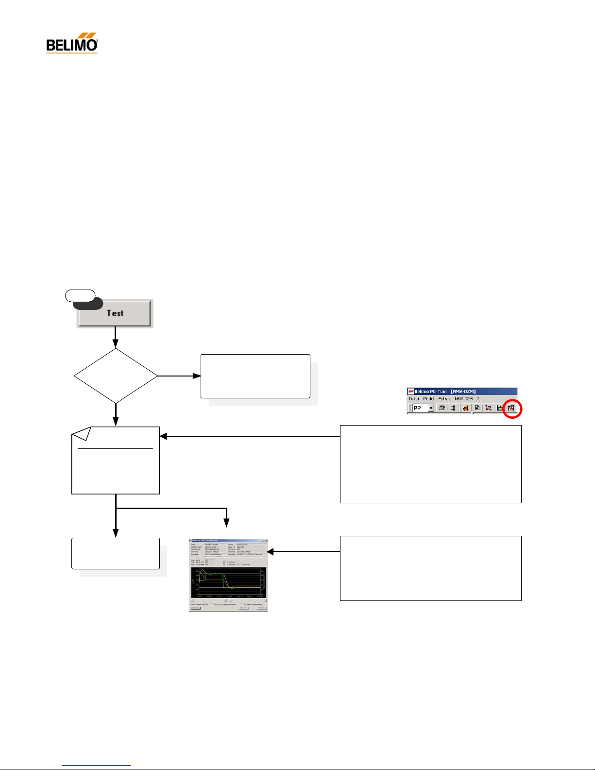
The sequence of the ‘Test’ function is as shown in the diagram below.
N-S5.1.1 Start/Stop
Start: with the ‘TEST ’ button
Stop: - with the <ESC> button
- with the ‘STOP’ button
- by interrupting communication
- by local initiation of synchronising or adaption
The ‘TEST’ function cannot be started when ‘OPERATION’ or ‘LIVE
TREND’ is activated.
Test report
As wi th ‘Live Trend’ the ‘Test’ function gener
ates a
xxx.tnd f
ile. The stored data can be displayed on
the screen after
wards and also be printed out if
necessary.
Further information see: N-S4.3 ‘Trend Recall’
Test-Sequence – file selection:
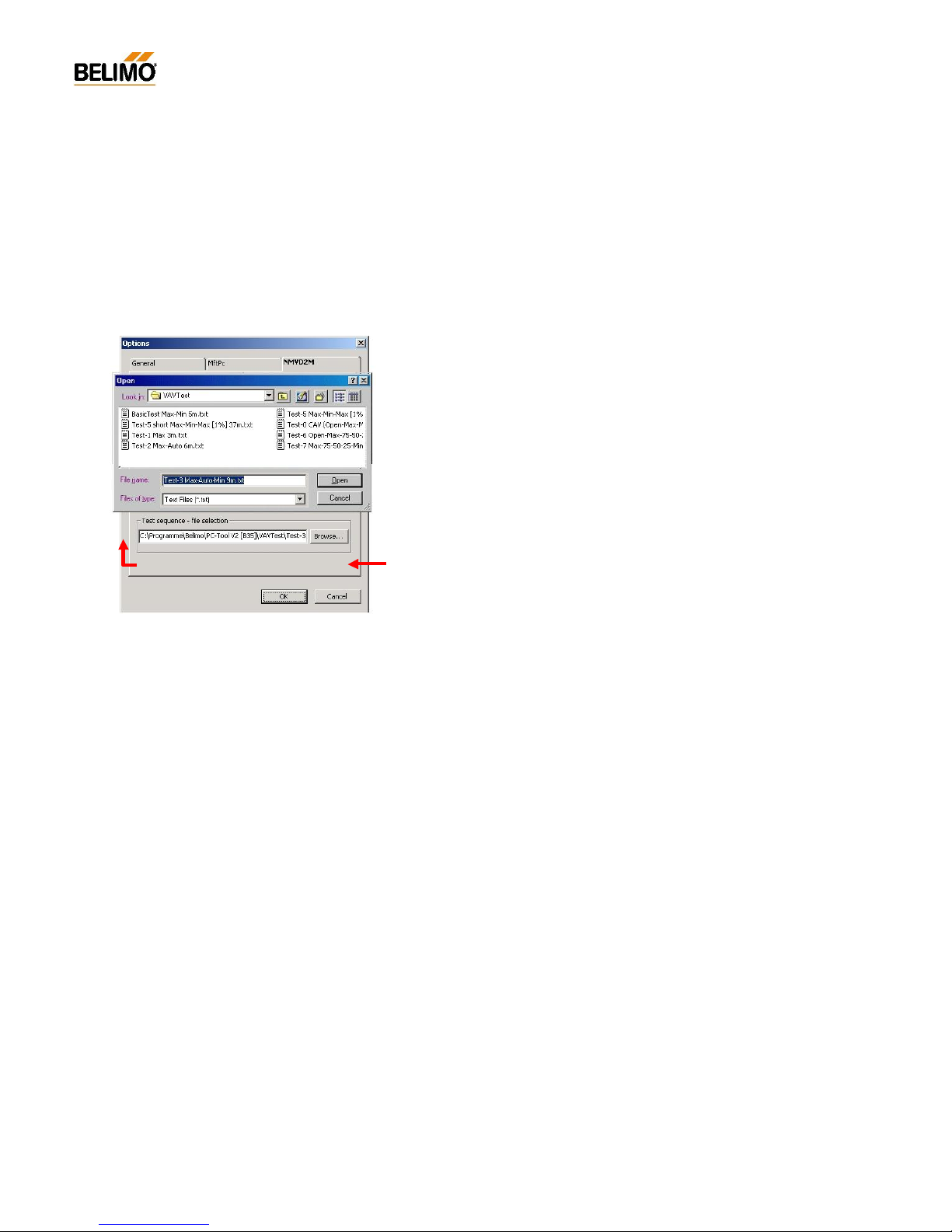
The Tool is able to provide various TestSequences. They can be selected from the ‘EXTRAS ¦ OPTIONS ¦ NMV-D2M’ menu in the ‘Test-
Sequence – file selection’ field.
See: N-S5.7 Selecting the Test-Sequences
N-S5.7.1 Available Test-Sequences
Check following points:
a) fan operation
b) position of fire dampers
c) NMV-D2M function
no
System supply
pressure ok?
Start
yes
Test terminated
Test sequence:
Step 1: V'max 120s
Step 2: V'min 120s
...
Step x: ...
Test -Seque nce:
z.B.: BasicTest Max-Min 5m.txt
Trend file:
z.B.: Fkt-prüf_G23-T_25.06.2002_Test_k.tnd
Test report VAV Box
Page 35
35
4A1PC-T V2.1 NMV-D2M-EN 11-02-04.doc PM VAV - Subject to technical changes
VAV – Module NMV-D2M
N-S5.1 ‘Test’ Diagnosis
That subject is explained in detail in a separate part. Several examples of
CAV- / VAV-boxes that are f unctioning either correctly or incorrectly are
described in detail. See N-P Diagnosis.
N-S5.3 Status display – Step control
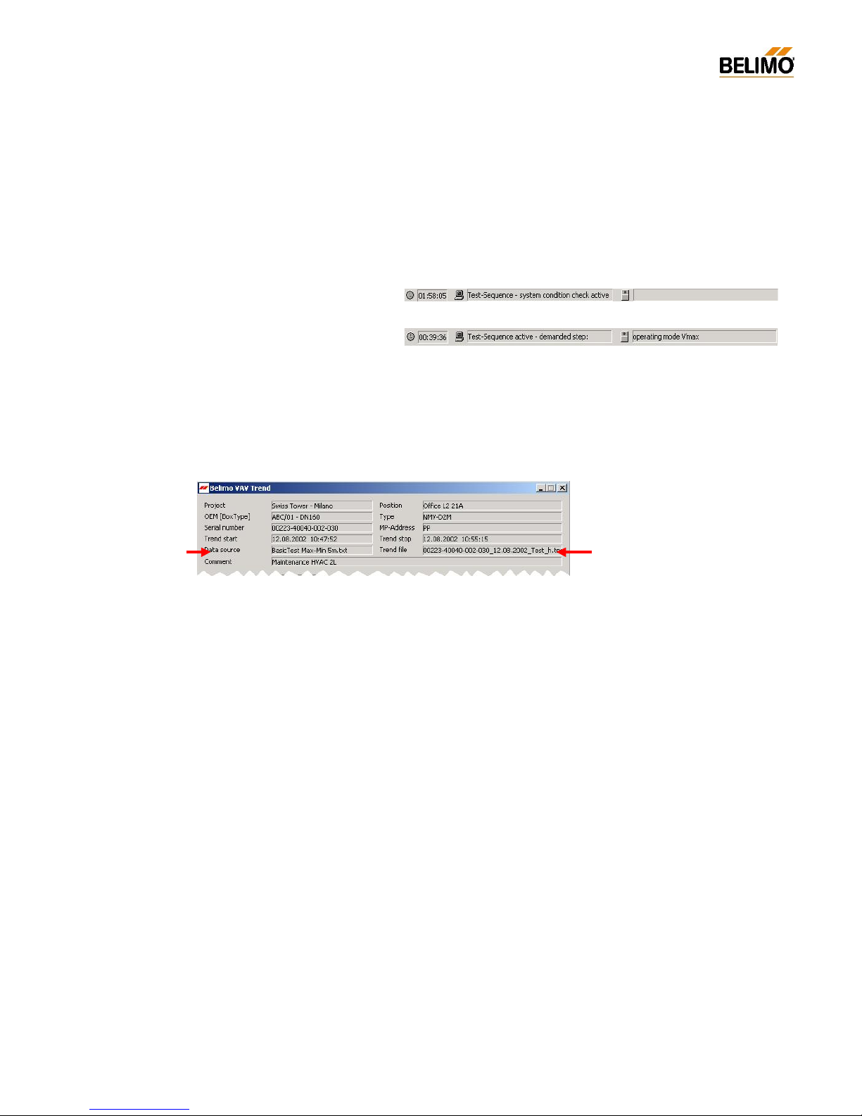
The status display provides information on the Test-Sequence and setpoint issue (Step):
- Check system pressure:
- Display current test step:
N-S5.4 Description of the elements
The ‘Test’ trend display will normally be the same as that from ‘Live
Trend’. See N-S4.1 Trend – Description of the elements.
The input file (defined Test-Sequence) and output file (Test log) are important for the test application.
N-S5.5 Selecting the operating step
Operating steps cannot be changed manually while ‘TEST’ is active.
N-S5.6 Display of actual values
The display o f actual values (‘Operation’ field) is not available during the
Test-Sequence.
N-S5.6.1 Voltage display in ‘Live Trend’
The voltage display for ‘Setpoint NMV-D2M’ and ‘Actual volumetric flow’ is
only available on the ‘Auto’ step during testing.
The NMV-D2M must always be set for conventional applications: Address
setting ‘PP’.
Test-Sequence
Input file
Test log
Output file
Page 36
36
4A1PC-T V2.1 NMV-D2M-EN 11-02-04.doc PM VAV - Subject to technical changes
VAV – Module NMV-D2M
N-S5.7 Selecting the Test-Sequence
In addition to the preset standard Basic Test-Sequence, a different sequenc e can be selected if neces sary. Depending on the functions to be
tested there are Test-Sequences available with different steps and values
of duration.
The Test-Sequence settings are made from the ‘EXTRAS... ¦ Options ¦
NMV-D2M’ menu.
N-S5.7.1 Available Test-Seq uences:
BasicTest Max-Min 5m.txt
- Function : System check / V’max 120 s / V’min 120 s
- Duration : Check + (2 x 120 s) = ca. 5 minutes
Test-0 CAV (Open-Max-Min-Close) 8m.txt
- Function : System check / Open / V’max / V’min / Close
Op en 90 s / V’ max & V’mi n 18 0 s / Close 90 s
- Duration : Check + 90 s + (2 x 180 s) + 90 s = ca. 9 minutes
Test-1 Max 3m.txt
- Function : System check / V’max 180 s
- Duration : Check + (1 x 180 s) = ca. 3…4 minutes
Test-2 Max-Auto 6m.txt
- Function : System check /
V’max 180 s / Auto (reference input w acti ve) 180 s
- Duration : Check + (2 x 180 s) = ca. 6…7 minutes
Test-3 Max-Auto-Min 9m.txt
- Function : System check /
V’max 180 s / Auto (reference input w acti ve) 180 s / V’min 180 s
- Duration : Check + (3 x 180 s) = ca. 9…10 minutes
Test-4 Max-Mid-Min 9m.txt
- Function : System check /
V’max 180 s / V’mid 180 s / V’min 180 s
- Duration : Check + (3 x 180 s) = ca. 9…10 minutes
Test-5 Max-Min-Max [1%] 37m.t xt
- Function : System check / V’max 120 s -> (V’max…V’min…V’max)
‘V’ sample with 1% increment: 10 s/step
- Duration : Check + 120 + (199 x 10 s) = ca. 36 minutes
Test-6 Open-Max-75-50-25-Min-Close 22m.txt
- Function : System check / Open / V’max / 75% / 50% / 25% / V’min / Close
180 s/step
- Duration : Check + (7 x 180 s) = ca. 22 minutes
Test-7 Max-75-50-25-Min 3h.txt
- Function : System check / Open / V’max / 75% / 50% / 25% / V’min
Open 120 s / 1800 s/step
- Duration : Check + 120 s + (5 x 30 m) = ca. 3 hours
Page 37

37
4A1PC-T V2.1 NMV-D2M-EN 11-02-04.doc PM VAV - Subject to technical changes
VAV – Module NMV-D2M
N-S5.8 Test log (Trend file)
As in the case of ‘Live Trend’, the ‘Test’ function also generates a xxx.tnd
file. The stored data can be displayed on the screen afterwards and be
printed out if necessary.
See: N-S4.3 ‘Trend Recall’ for further information.
Each Test (Trend) file is stored under a unique name.
- File name
Default:
- structure: serial number_date_test_index.tnd
e.g.: 00151-10002-002-032_15.04.2002_Test_f.tnd
User-defined name:
Enter the Trend file name in the ‘Project Data form’ dialogue box.
- structure: 15characters _date__test_index.tnd
e.g.: Office1 2 -1-OG ZUL_12.04.2002_Test_a.tnd
- Storage directory (path)
Default:
As a subdirectory of the PC-Tool program directory:
...\VAVTrend
User-defined path:
The user c an select the destination directory in the menu
‘EXTRAS ¦ OPTIONS... ¦ NMV-D2M’.
All trend files are then stored in that directory.
N-S5.9 Read Test log (Trend Recall <F6>)
See N-S4.3 Trend Recall / <F6>
Project Data form <F4>
This allows the project-specific and trendspecific data, such as file names, to be entered.
The data is used by the log, print, trend and
test functions. T he
data entries remain valid
until they are changed or deleted.
-> Blank fields are allowed
Practical tip – File clearing
If the trend function is used ofte n a large
number of trend files will be accumulated.
Therefore, after plotting, it is advisable to:
- transfer the data to a project directory
- delete the data if it is no long er needed
Page 38
38
4A1PC-T V2.1 NMV-D2M-EN 11-02-04.doc PM VAV - Subject to technical changes
VAV – Module NMV-D2M
N-P Diagnosis
The ‘Test’ function in the ‘Service’ register allows VAV-/CAV-boxes to be
diagnosed in easy and efficient fashion.
An active check of system supply pressure provides an indication of the
function and efficiency of the pressurising device and its control system.
Test reports produced with this f unction serve as test logs, as plant
documentation and, the event of a fault, as an aid for the control and ventilation technicians involved.
By means of 10 examples the results of the diagnosis function are explained and the most suitable Test-Sequences for similar situations suggested. Due to the great variety of
Plant concepts, appropriate for particular types of buildings
Plant sizing and rating
Control strategies
Design-related differences between different makes of air box
the examples shown here may differ from the records obtained from your
plant.
Below are descriptions and explanations of 10 examples of VAV- / CAV boxes that are functioning either correctly or incorrectly.
N-P1 Index of recorded Test-Sequences
# Air unit type..................................................................................................Function / Fault
1. VAV..............................................................................correct function
2. CAV..............................................................................correct function
3. VAV / CAV................................................no system supply pressure
4. VAV / CAV.................................. insufficient system supply pressure
5. VAV / CAV....................................excessive system supply pressure
6. VAV / CAV................................................................ oversized air box
7. VAV / CAV................................................. wrong direction of rotation
8. VAV / CAV............................. leakage air with VAV controller closed
9. VAV..............................................................unstable reference signal
10. VAV..........................................unsuitable reference signal <-> Mode
System test
The following points should be checked before any faults
in the installation or faults in operation of the VAV/CAVboxes are recorded and analysed:
- Installation: anti-rotation device / spindle attachment /
sensor connection
- Connection: power / wiring / polarity
- Control: conventional or bus system
See 4. NMV-D2M Product Information
for more information on function testin g and NMV-
D2M
analysis options.
Planning and installation faults
and malfunctions resulting from them can only be cor-
rected to a limited extent and sometimes not at all.
Therefore, it is essential to adhere to the sizing and
installation instructions provided by the manu
facturer of
the air box.
System supply pressure
A functioning VAV-/CAV-installation needs a cor
rectly
designed and adjusted pressurizing device.
The air volume controller adjusts the control dam
per of
the VAV-/CAV-box according to the
value of supply
pressure available. If there is no supply pressure, or
insufficient pressure, the control damper will remain in
the open position. T his does not mean that the air volume controller is malfunc
tioning but simply the result of
the lack of air. The pressure con
ditions in the ducting
system must be correct in order for control to be effective.
Page 39
39
4A1PC-T V2.1 NMV-D2M-EN 11-02-04.doc PM VAV - Subject to technical changes
VAV – Module NMV-D2M
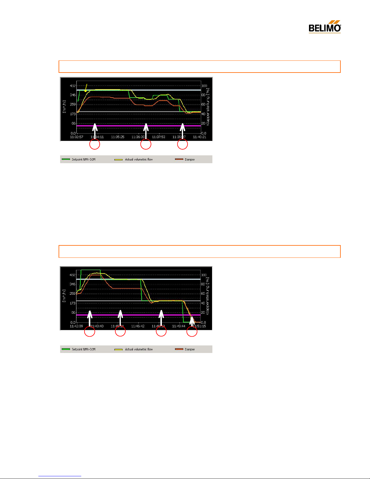
Legend
Sequence
a) - Step 1: V’max
- Volumetric flow at setpoint
- Damper in control range
b) - Step 2: Auto [external control signal]
- Actual value following setpoint
- Damper in control range
c) - Step 3: V’min
- Volumetric flow at setpoint
- Damper in control range
N-P1.1 VAV-Box
................................................................................................................................
correct function
Conclusion
The correc tly set up VAV air box is f unction
ing
correctly over the whole preset wor
king range
V’min ... V’max.
Suitable Test-Sequences
- Test 3 Max-Auto-Min 9m.txt
- or BasicTest Max-Min 5m.txt (without Auto Step)
NMV-D2M – Diagnosis
a b c
S
A
D
Suitable Test-Sequences
- Test 0 CAV (Open-Max-Min-Close) 8m.txt
- Test 4 Max-Mid-Min 9m.txt
- BasicTest Max-Min 5m.txt
a
b
d
N-P1.2 CAV-Box
................................................................................................................................
correct function
Sequence
a) - Step 1: Damper open (uncontrolled)
- Volumetric flow depends on supply
pressure
- Damper 100% open
b) - Step 2: V’max
- Volumetric flow at setpoint
- Damper in control range
c) - Step 3: V’min
- Volumetric flow at setpoint
- Damper in control range
c) - Step 4: Damper closed (uncontrolled)
- Volumetric flow zero [m
3
/h] / [l/s]
- Damper closed
Conclusion
The correc tly set up VAV air box is f unction
ing
correctly over the whole preset wor
king range
V’min ... V’max.
c
S
A
D
Legend
Page 40
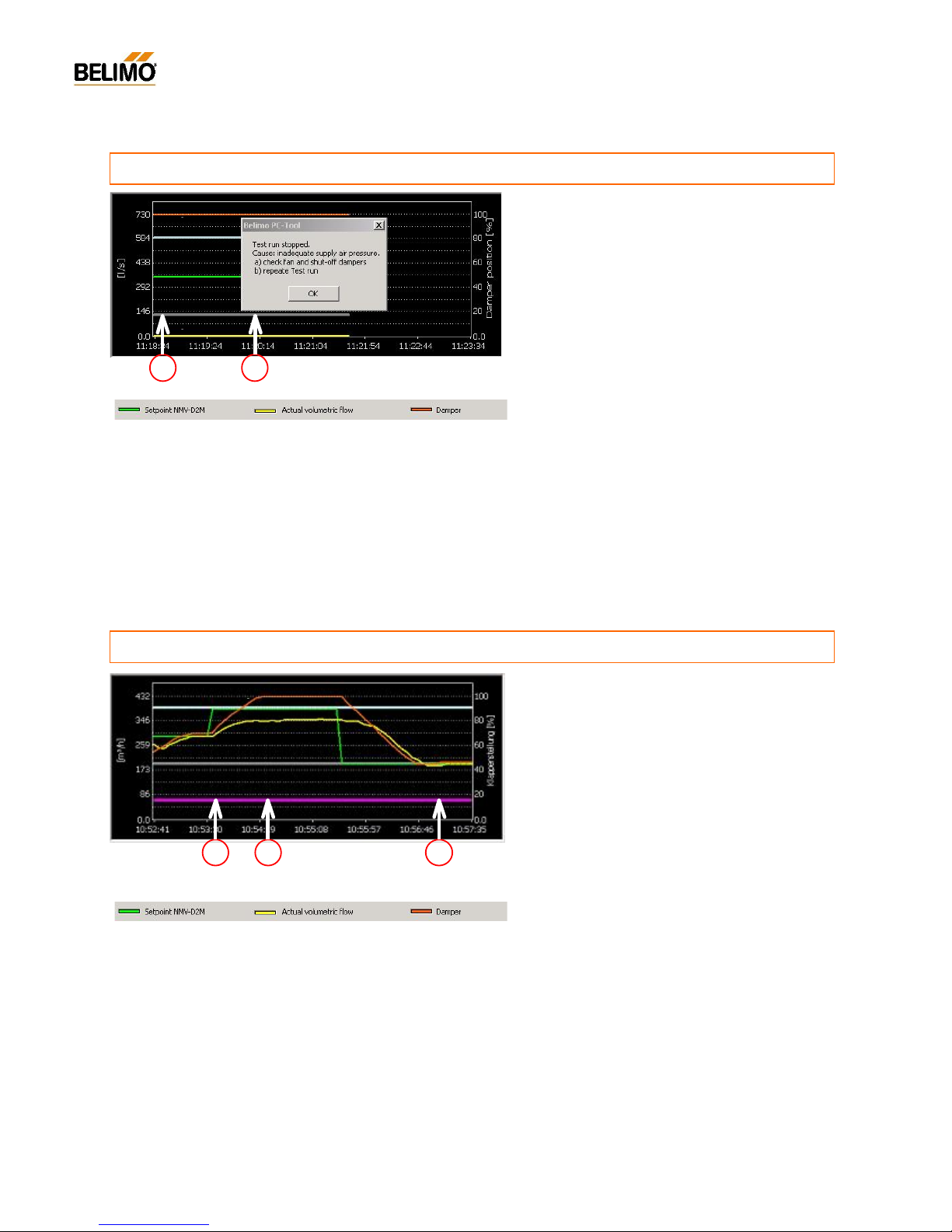
40
4A1PC-T V2.1 NMV-D2M-EN 11-02-04.doc PM VAV - Subject to technical changes
VAV – Module NMV-D2M
Legend
Sequence
a) Test start ‘Check system supply pressure’
- System test: setpoint V’mid
- Volumetric flow zero [m
3
/h] / [l/s]
- Damper 100% open
b) - Test-Sequence discontinued
N-P1.3 VAV- / CAV-Box
.........................................................................................
no system supply pressure
Suggstion for a remedy
a) Check fan and pressure control, including the
protective devices
b) Check the function of the upstream dampers
(control and fire dampers)
c) Check damper direction of rotation
d) Rectify fault and repeat test
Suitable Test-Sequences
- BasicTest Max-Min 5m.txt
Note:
The Test-Sequence is discontinued because of the lack of system
supply pressure. Fault alarm: ‘Inadequate supply air pressure’
Possible faults
- Fan pressure control defective or inoperative
- Protective devic e triggered (fuse, thermal trip)
- Upstream fire damper closed
- Damper rotation incorrectly set
a
b
Sequence
a) Step 1: V’max
b) Setpoint [V’max]
- Volumetric flow does not reach setpoint
- Damper 100% open
c) Step 2: V’min
- Volumetric flow a t setpoint
- Damper in control range
Suggestion for a remedy
1)
Increase supp ly pressure (increase pressure
control setpoint), if this is impossible temporar
ily
isolate sever a l air units on the same section at the
same time
2) Repeat test
3) Check fan and pressure control and set correctly.
Suitable Test-Sequences
- BasicTest Max-Min 5m.txt
- Test 4 Max-Mid-Min 9m.txt
Note:
If the system does not attain the required supply pressure – during the
test start – the Test-Sequence is discontinued and the fault alarm ‘Inadequate supply ai r pressure’ is given.
During the installation and commissioning phases of plants they are
often set up for manual operation, i.e. max imum volumetric flow.
Result: Insufficient system supply air pressure.
Possible faults
- Fan or pressure control defec tive
- Pressure c ontrol setpoin t incorrectly set
- Plant not set up or set up inc orrectly
- All VAV- / CAV air boxes being operated at max.
volumetric flow (commissioning)
a
b c
S
A
D
N-P1.4 VAV- / CAV-Box
......................................................................
insufficient system supply pressure
S
A
D
NMV-D2M –
Diagnosis
Legend
Page 41
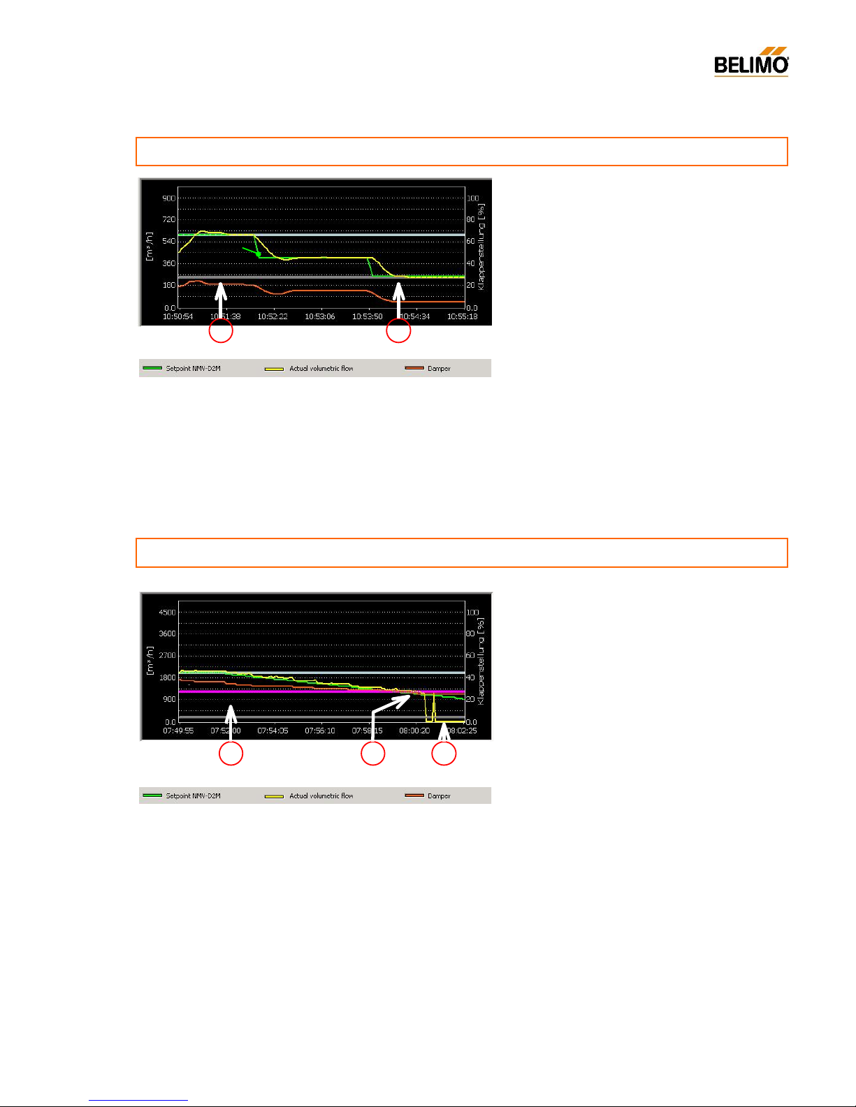
41
4A1PC-T V2.1 NMV-D2M-EN 11-02-04.doc PM VAV - Subject to technical changes
VAV – Module NMV-D2M
Legend
Sequence
a) Step 1: V’max
- Volumetric flow at setpoint
- Damper control range ~42%
b) Step 3: V’min
- Volumetric flow at setpoint
- Damper control range ~28%
N-P1.5 VAV- / CAV-Box
.........................................................................
excessive system supply pressure
Suggestion for optimising
Set the fan and pressure control so that the damper
position of the VA-V/ CAV-boxes in V’ max opera
tion is
approximately 80%
Suitable Test-Sequences
- BasicTest Max-Min 5m.txt
Cause
Fan or pressure control rated too high or set up too
high.
a
b
S
A
D
Suggestion for a remedy
- Increase the operating flow rate setting so th at the
V’min volumetric flow setting corresponds to an active differential pressure setting of more than 2 Pa.
- Investigate changing the air bo x (smaller nominal
diameter).
N-P1.6 VAV- / CAV-Box
.............................................................................................................
oversized air unit
Sequence
a) The setpoint is reduced in 1% steps
b) - Setpoint less than active differential pressure
2 Pa
- NMV-D2M function
Leakage-flow suppression activated
c) - Setpoint less tha n active differential pressure
2 Pa
- Actual volumetric flow rate = 0
Suitable Test-Sequences
- Test 5 Max-Min-Max [1%] 37m.txt
- Test 4 Max-Mid-Min 9m.txt
Note:
If the system does not attain the required supply pressure – during the
Test start – the Test-Sequence is discontinued and the fault alarm ‘Inadequate supply ai r pressure’ i s given.
See:
- Air box manufacturer’s documentation on minimum air flow for the VAV-/CAVbox
- section ‘N-S1.2.1 Control range’
Causes and consequences
- VAV-/CAV-box oversized for the required value of
volumetric flow
- Oversized air boxes are being operated in a difficultto-control, sometimes uncontrollable, range
- The function range of the VAV-/CAV-box must not
exceed 2 Pa. Otherwise the air box will be operated
near leakage-flow suppression, i.e. in the uncontrollable range.
a
b c
S
A
D
NMV-D2M – Diagnosis
Legend
Page 42
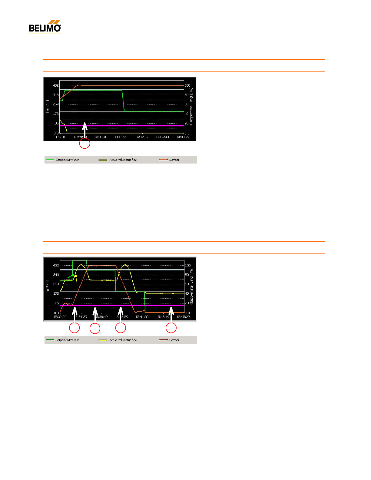
42
4A1PC-T V2.1 NMV-D2M-EN 11-02-04.doc PM VAV - Subject to technical changes
VAV – Module NMV-D2M
Legend
Legend
Sequence
a) Te st s tart ‘Ch eck sy ste m supp ly pr ess ure ’
- [System test: Setpoint V’mid]
- Actual value zero [m3/h] / [l/s]
- Damper 100% open
N-P1.7 VAV- / CAV-Box
..........................................................................................
wrong direction of rotation
Suggestion for a remedy
a)
Check direction of rotation (‘Ser vice’ register
‘OPEN’ or ‘CLOSE’ operation)
b) Correct direction of rotation or mount the actuator
correctly (note the mark on the damper blade)
Suitable Test-Sequences
- BasicTest Max-Min 5m.txt
Note:
The Test-Sequence is discontinued because of the lack of system
supply pressure. Fault alarm: ‘ Inadequate supply air pressure’ is given.
Possible faults
- Incorrect direc tion of rotation
- NMV-D2M shaft connector and damper spindle
installed with offset (90°)
a
S
A
D
Sequence
a) Step 1: Damper open (uncontrolled)
- Volumetric flow a lready very high when the
damper is only slightly open !
- Damper 20...100% open
b) Step 2: V’max
- Actual value not reaching setpoint
- Damper apparently 100% open
c) Step 3: V’min
- Volume increases despite the damper closing
and being clearly above the setpoint !
- Damper in control range
d) Step 4: Damper closed
- Actual value: Volumetric flow present de
spite the
damper apparently being closed !
- Damper appears to be closed
Suggestion for a remedy
Remove the NMV-
D2M and match the closed position
correctly to that of the closed damper blade.
Suitable Test-Sequences
- Test 0 CAV (Open-Max-Min-Close) 8m.txt
Note:
If the system does not attain the required supply pressure – during the
Test start – the Test-Sequence is discontinued and the fault alarm ‘I nadequate supply ai r pressure’ is given.
The spindle is fitted with clear offset in order to record this symp
tom. A s
a result different values of offset can occur on-site in this situation.
Possible fault
0° position of the actuator does not correspond to that
of the closed damper blade. This pro
duces offset, i.e.
the damper remains open al
though the actua tor is
closed. When the actua
tor is 100% open the damper
is already moving back in the ‘Close’ direction (90°).
a
b
d
N-P1.8 VAV- / CAV-Box
.................................................................
leakage air with VAV controller closed
S
A
D
c
NMV-D2M –
Diagnosis
Page 43
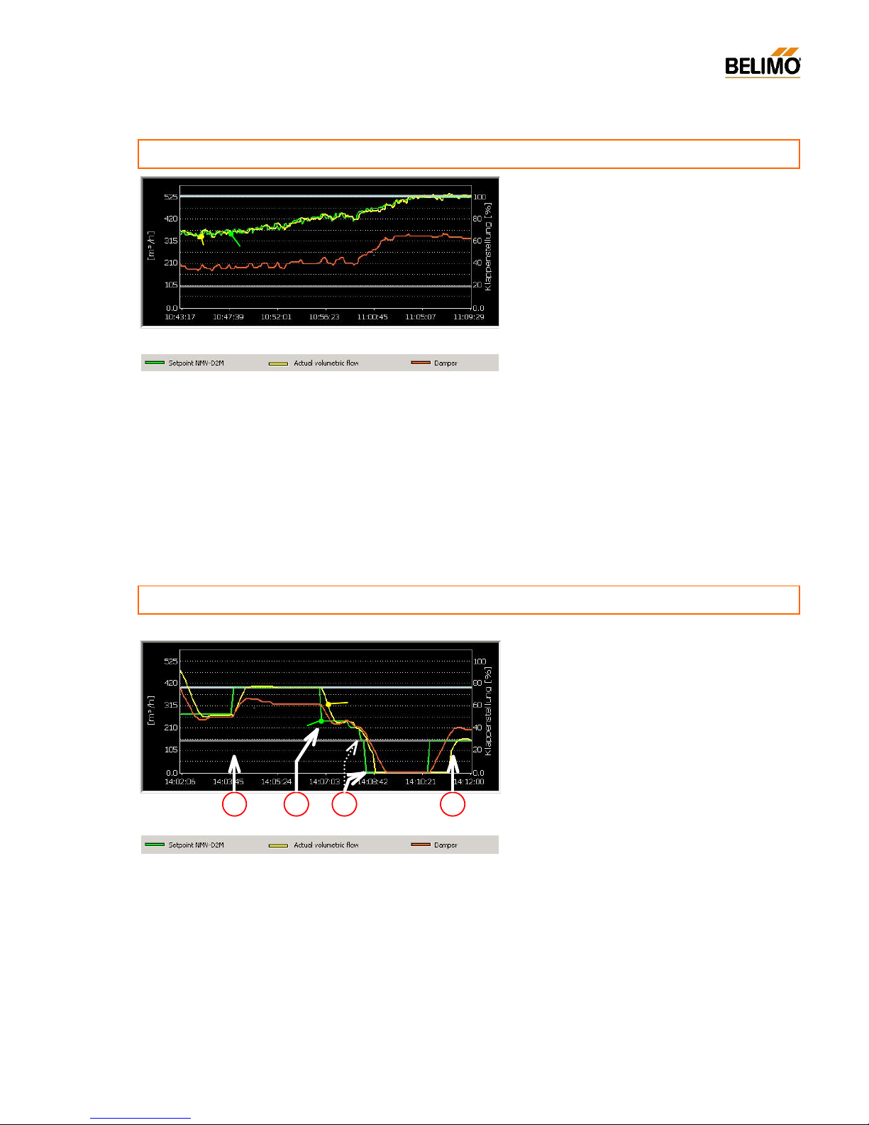
43
4A1PC-T V2.1 NMV-D2M-EN 11-02-04.doc PM VAV - Subject to technical changes
VAV – Module NMV-D2M
Sequence
- Reference signal hunting
- Volumetric flow following the setpoint
- Damper hunting in the control range
N-P1.9 VAV-Box
............................................................................................................
unstable reference signal
Suggestions for improvements
Match the reference control circuit correctly and adapt
the controller parameters (P-
band, etc.) to suit the
complexity of the plant.
Investig ate the positioning of the room tempera
ture
sensor. Mounting (e.g. tension from the con
duit),
draughts, sun, etc. can have a direct effect on the
quality of control.
Suitable Test-Sequences
- Test 2 Max-Auto 6m.txt
- Test 3 Max-Auto-Min 9m.txt
-
Record the symptom with ‘Live Trend’ over an extended period of time,
e.g. overnight. This allows intermittent faults to be lo
cated more easily.
Note:
The Test-Sequence is discontinued because of the lack of system
supply pressure. Fault alarm: ‘Inadequate supply air pr essure’ is given.
Cause and consequence
Room temperature control circuits are usually slow-
respons e control lo ops: A te ndency to hunt is an
indication of either a lack of settings or incorrect settings.
The VAV controller follows the reference signal, which
is its task. Therefore, when a system is hunt
ing it
means that the damper actuator is in con
stant motion.
So an adverse effect on service life is an inevitable
consequence.
Pres
sure control is affected and, as a result, also the
remaining VAV-boxes in the same section.
N-P1.10 VAV-Box
................................................................................
unsuitable reference signal <-> Mode
S A D
Sequence
a) Step 1 + 3: V’max / V’min
Function correct
b) Step 2: Auto (reference input active)
- DDC output, room controller: 5.0 V
- NMV-D2M regulates to 245 instead of 275 m3/h
c) Step 2: Auto (reference input active)
- DDC output, room controller: 0.0 V
- Damper closes completely instead of to V’min
Suggestions for improvements
a) Change over the NMV-
D2M to the 0...10 V mode,
or
b) Change over the DDC output, room controller to
working range 2...10 V (if this is possible).
Suitable Test-Sequences
- Test 2 Max-Auto 6m.txt
- Test 3 Max-Auto-Min 9m.txt
Note:
If the system does not attain the required supply pressure – during the
test start – the Test-Sequence is discontinued and the fault alarm ‘In-
adequate supply ai r pressure’ is given.
Natura lly , the opposi te situ ation can also ar ise: ‘D DC 2.. .10 V, NMV-
D2M 0...10 V’.
In this case the result is a worse deviatio n in the V’min range.
Cause
- The external reference signal (DDC, room temperature controller) has a working range of 0...10 V
- The NMV-D2M is is set to 2...10 V mode
Function: 0 V = Close
2...10 V = V’min...V’max
The NMV-D2M is closed completely by the 0 V signal ins tead of to the required V’ min (s ee c).
a
b c
S
A
D
a
NMV-D2M – Diagnosis
Legend
Legend
Page 44
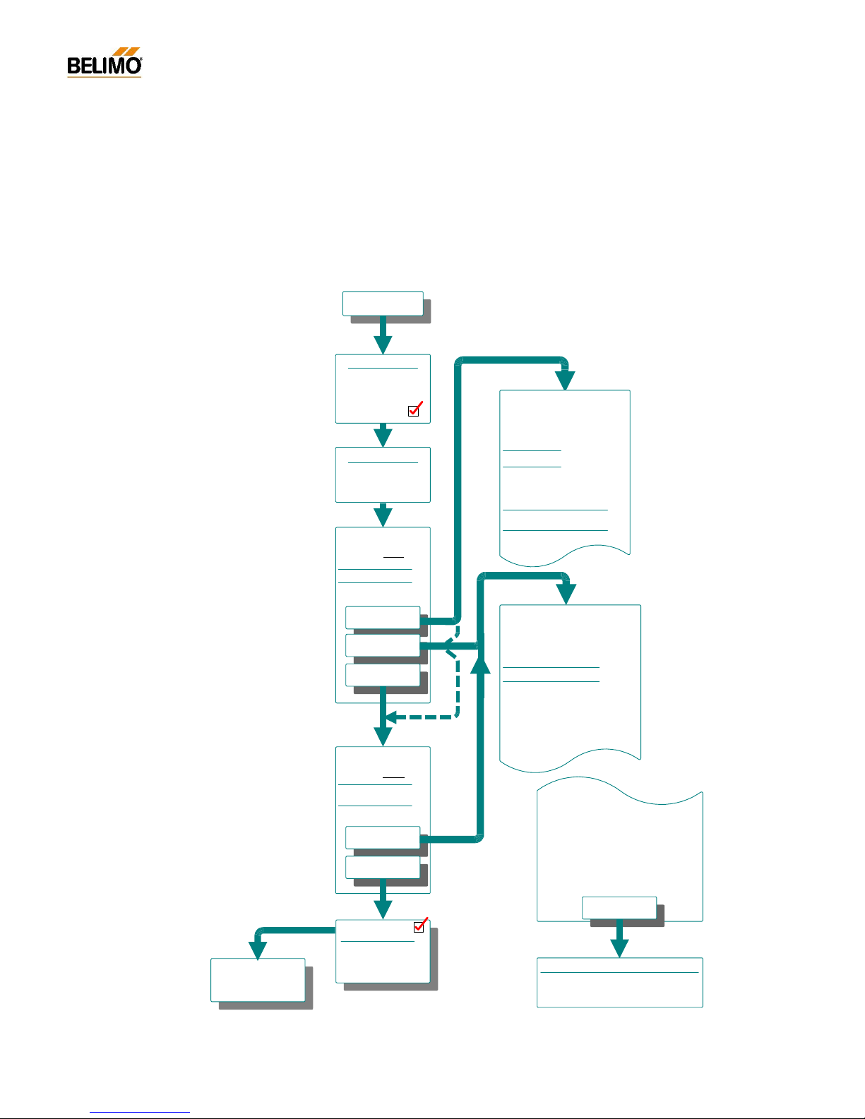
44
4A1PC-T V2.1 NMV-D2M-EN 11-02-04.doc PM VAV - Subject to technical changes
VAV – Module NMV-D2M
N-D Miscellaneous
N-D1 Function checks of the NMV-D2M
Detailed information on function checks for the NMV-D2M will be found in
4. NMV-D2M Product Information. Some extracts are described on the
two following pages, the Level 2 and 3 function checks.
N-D1.1 ‘Level 2’ function check
Possible cause:
c) inadequate supply pressure
1)
d) pressure sensor / pick-up device
hoses damaged, loose or dirty
c) check fan operation, correct
control parameters
d) measure active pressure
with Pascal meter, examine
pick-up devicee and hoses
Level 2 -
Function check
Reference value input w
Isolate signal from DDC,
room contro ller or CAV
step control
(terminal # 3)
Preconditions:
-
24 V power supply
- damper function
- Supply pressure
checked and OK
Test
Operating volumetric-
flow: V'min
Reaction:
terminal 3 open
Damp er closed
Damper open
check
Possible cause:
a) V'min setting: 0%
b) V'min setting gives active
pressure below 2 Pa
(Creep flow suppression active)
try V'min setting higher, e.g. 50%
check
Next Step:
- test V'max function
Test
Operating volumetric
flow: V
'max
Reaction:
Link terminal 2+3
Damper open
Actual flow =
Reference flow
Actual flow =
Reference flow
1) inadequ ate supply pressure
N
ote: It happens quite oft en during a system
commissioning that all VAV units are being set
to V'max through the DDC control -> Result:
shortage of air
If this is the case, increase the supply pressure.
If this is impossible, temporarily:
- reduce the V'max setting
- isolate one or more VAV units on the same
section
Actual flow =
Reference flow
Check fan and correct settings
Re-establish the original status:
- reset the V'max setting
- de-isolate the VAV units
Check function
DDC / Room-controller
or Step control
2. Level
Function check
- set V'min and V'max to
Orginal values
- connect reference signal
to Terminal 3
Page 45
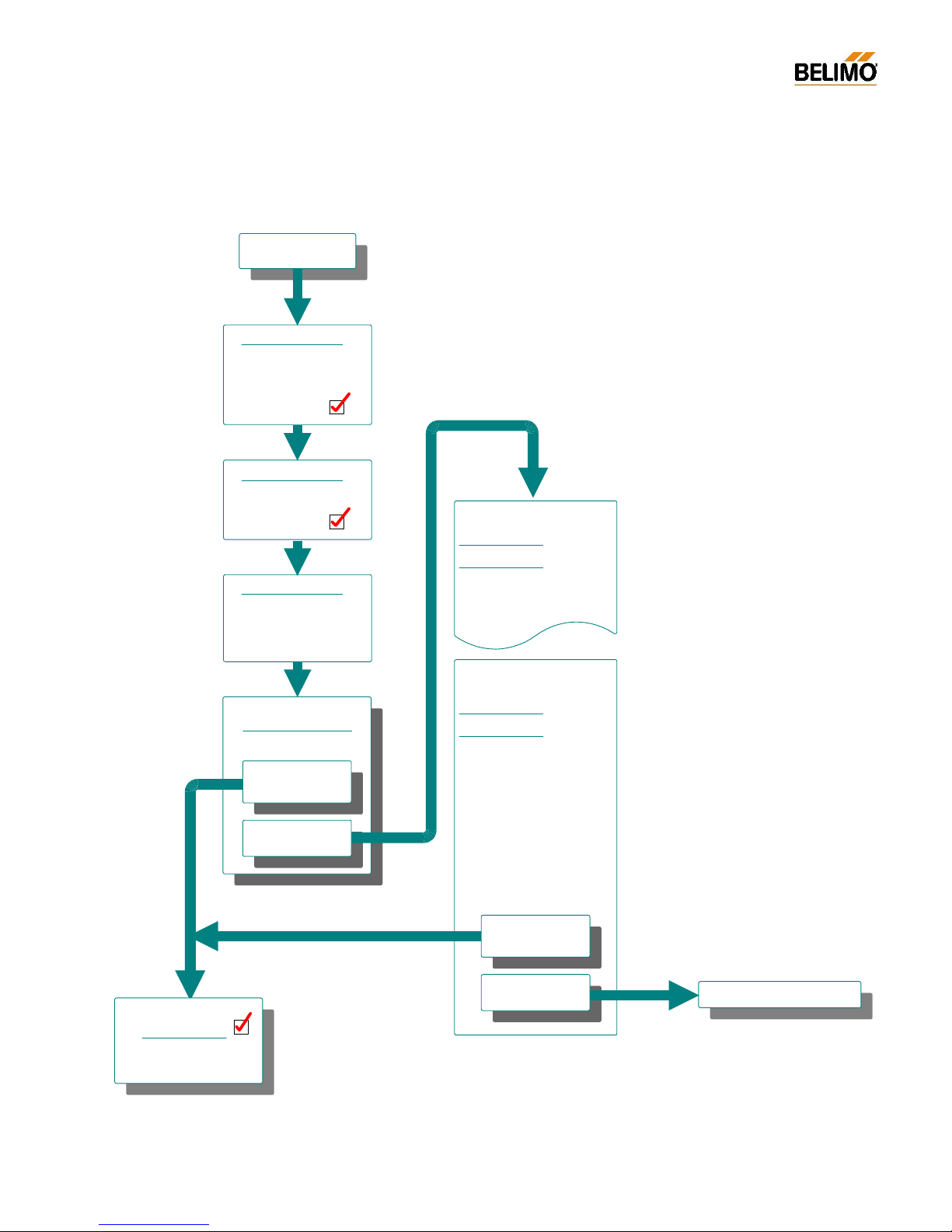
45
4A1PC-T V2.1 NMV-D2M-EN 11-02-04.doc PM VAV - Subject to technical changes
VAV – Module NMV-D2M
N-D1.2 ‘Level 3’ function check
Level 3 -
Function check
Preconditions:
- 24 V power supply
- damper function
- supply pressure present
checked and OK
Bus cabeling:
- check conditions
checked and OK
Connect tool *):
- connect PC Tool
- select address of NMV D2M to be tested
Activate 'Test' function
(menu option 'Service')
Reaction:
NMV-D2M follows
Test-Sequence
Actautor still
stationary
Level 3
Function Check
Continue with whole
system test if necessary
Contact the manufacturer
Possible cause:
Damper blade jammed
- check free movement of
damper by hand
- correct the fault
Test
Possible cause:
The required NMV-D2M has a
different address
- compare the Serial No. in
the actuator identifier with
the Serial No. on the NMV D2M
-> change to the required
NMV-D2M, repeat the test
Test
NMV-D2M follows
Test-Sequence
Actautor still
stationary
Note
Remember that, in bus mode, no tools may
be connected to the communication socket
of the NMV-D2M.
In this mode tools may only be connected
via the MFT-H socket of the UK24LON .
Page 46

46
4A1PC-T V2.1 NMV-D2M-EN 11-02-04.doc PM VAV - Subject to technical changes
VAV – Module NMV-D2M
N-D2 Formulae
- Formulae for conve rting units
m3/h -> l/s Volumetric flow [m3/h] / 3.6
m3/h -> cfm Volumetric flow [m3/h] / 1.6990107955
l/s -> m
3
/h Vo lumetric flow [l/s] * 3.6
l/s -> cfm Volumetric f low [l/s] * 2.1188800033
cfm -> m
3
/h Volumetric flow [cfm] * 1.6990107955
cfm -> l/s Volumetric flow [cfm] / 2.1188800033
- Formulae for calculating area
Area, circle A = 0.785 x d
2
Area, rectangle A = l x b
- Formulae for calculating volumetric flow
Volumetric flow [m
3
/h] = (A [m2] x V [m3]) x 3600
- Formulae for calculating velocity
Velocity [m/s] = Volumetric flow [m
3
/h] / Area [m2]
- Formulae for volumetric flow and differential pressure
- Volumetric flow [m
3
/h]
c - Constant differential pressure sensor,
manufacturer‘s value, see manufacturer’s data
- Differential pressure from measuring orifice (cross, bar) [Pa]
- Density [kg/m
3
]; 1.2 kg/m3 at 1013 hPa and 20°C
- Formulae for pressure calculations
1 mbar = 0,001 bar = 100 Pa
1 mmH
2
O = 9,80665 Pa
V
p
V
pc
=
p
=
2
c
V
Page 47

47
4A1PC-T V2.1 NMV-D2M-EN 11-02-04.doc PM VAV - Subject to technical changes
VAV – Module NMV-D2M
Notes
Page 48
48
4A1PC-T V2.1 NMV-D2M-EN 11-02-04.doc PM VAV - Subject to technical changes
VAV – Module NMV-D2M
 Loading...