

Page 1
22
.
LR...24-SR Actuators, Proportiona
l
ls
k
e
y
W
ldi
W
g
)
n
SR
SR
]
]
n
U
Ω
p
n
ide
SR
SR
y
1)
g
l
VA
†
1A/-2-14
s
l
d
n
)
)
1
)
8
08
ode
LRB24-SR-T LRX24-SR-T w/Terminal Bloc
LRB24-SR LRX24-SR w/3ft. cabl
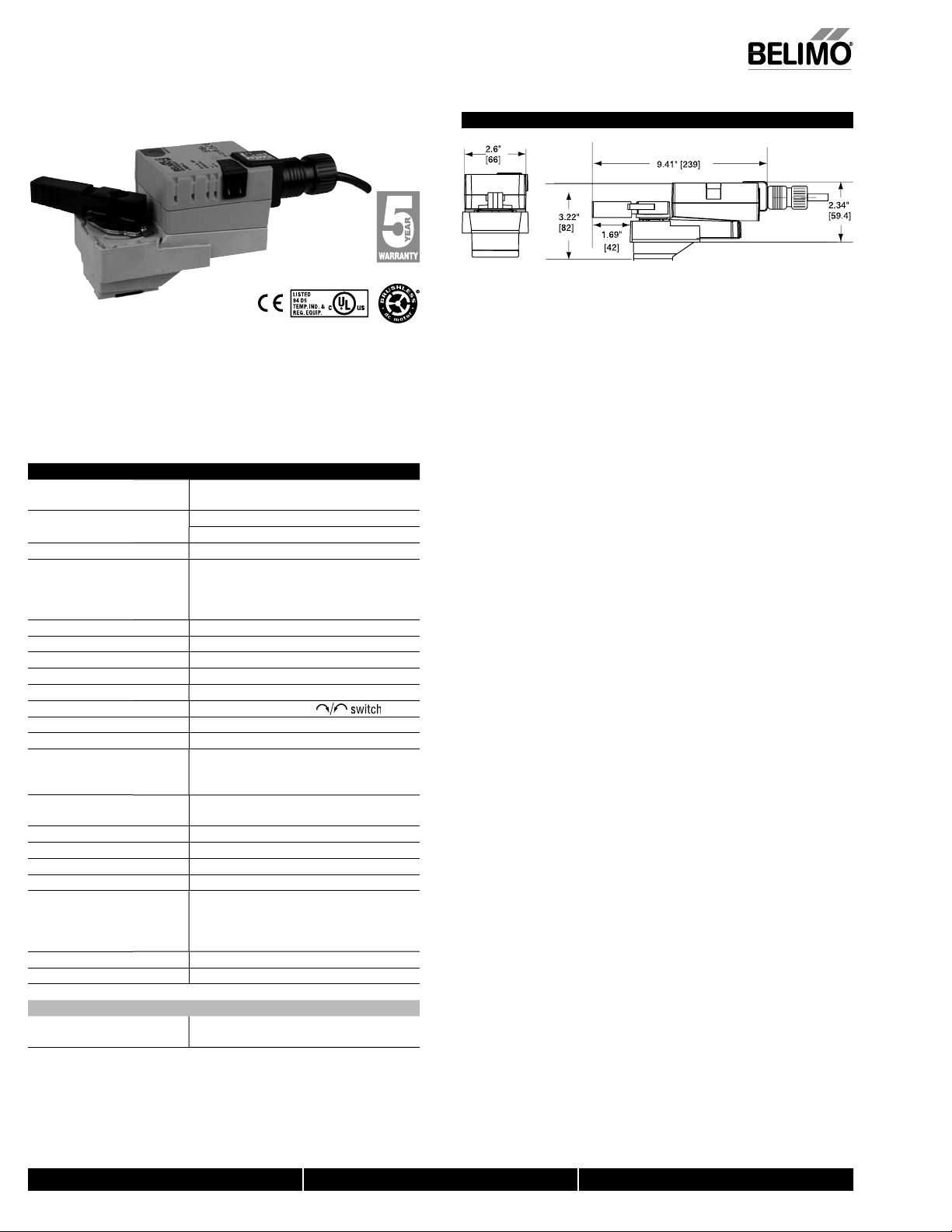
Technical Data
Power suppl
ower consumption running.5
Transformer sizin
ectrical connectio
LRB24LRX24-
Overload protectio
perating range Y 2 to 10 VDC, 4 to 20 mA
eedback output
Input impedance
Angle of rotation 90°, adjustable with mechanical sto
Direction of rotation reversible with protected
Position indicatio
anual overr
unning time
LRB24LRX24-
Humidit
Ambient temperature
torage temperature
Housin
ousing materia
gency listings
oise leve
uality standar
LR...24-SR-T
Electrical connectio
† Rated impulse voltage 800V, Control pollution degree 3, Type of action
1.B for -S models
24 VAC ± 20% 50/60 Hz
24 VDC ± 10%
o
ng
.4
3 VA (class 2 power source
conduit connector
8 GA, plenum rated cable
3 ft [1m
3 ft [1m], 10 ft [3m], 16 ft [5m
electronic throughout 0° to 95° rotation
to 10 VDC, max 0.5 mA
00 k
(0.1 mA), 500
handle
external push button
constant independent of load
seconds
50, 95, 60, 45, 35 seconds
5 to 95% RH non-condensing
6073022°F to 122°F [-30°C to 50°C]
40°F to 176°F [-40°C to 80°C]
EMA 2/IP54
-5
cULus according to UL 60730-
AN/CSA E60730-1:02, CE according to
2004/108/EC and 2006/95/EC for line voltage
nd/or –S version
<35 dB(A)
ISO 9001
crew terminal (for 26 to 14 GA wire
protected (NEMA 2/IP20
Dimensions
-2W-
D14
,
N40013 - 06/11 - Subject to change. © Belimo Aircontrols (USA), Inc
800-543-9038 USA 866-805-7089 CANADA 203-791-8396 LATIN AMERICA
Page 2
S
©
S
.
!
.
.
y
!
dli
jury
LR...24-SR Actuators, Proportiona
l
65
08
65
08
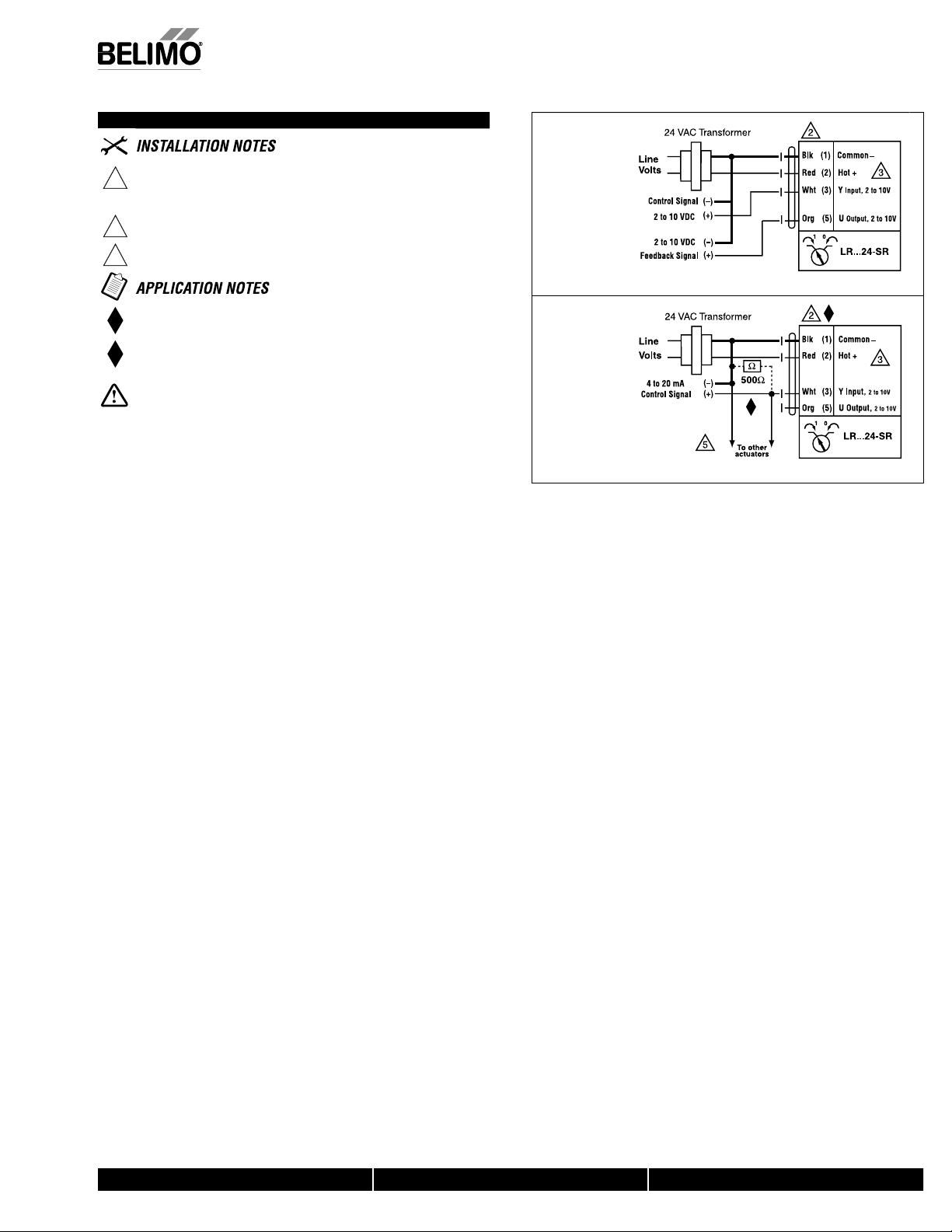
Wiring Diagrams
AUTION Equipment damage
Actuators may be connected in parallel
ower consumption and input impedance must be observed.
Actuators may also be powered by 24 VDC
Only connect common to neg. (–) leg of control circuits.
Meets cULus or UL and CSA requirements without the
need of an electrical ground connection.
The ZG-R01 500 Ω resistor converts the 4 to 20 mA control signal to 2
to 10 VDC, up to 2 actuators ma
be connected in parallel.
ARNINGive Electrical Components
During installation, testing, servicing and troubleshooting of this product, it may
be necessary to work with live electrical components. Have a qualifi ed licensed electrician
or other individual who has been properly trained in han
perform these tasks. Failure to follow all electrical safety precautions when exposed to live
electrical components could result in death or serious in
ng live electrical components
.
-LR-
W2
to 10 VDC control
-LR-
W2
4 to 20 mA control
A), Inc
Belimo Aircontrols (U
ubject to change.
N40013 - 06/11 -
800-543-9038 USA 866-805-7089 CANADA 203-791-8396 LATIN AMERICA
 Loading...