

Page 1
93
P
pply
50/60 Hz
0%
P
n
g
)
E
n
e
r
]
n
g
Y
)
Inp
e
Ω
)
Feedback
U
x
e
A
n
p
e
e
]
on
s
ch
Positi
n
)
Manual ove
de
n
R
e
)
)
H
y
)
A
e
]
S
e
H
g
NEMA
H
l
UL94-5
Ag
gs
CAN/CS
Noise level
)
g
ee
Q
d
900
t
LMB(X)
24-
MFT
®
.
n
y
y
g
.
n
g
ill p
.
h
(X)
g
g
.
.
]
3
2" [
]
0.86" [22]
3
9
]
6
66]
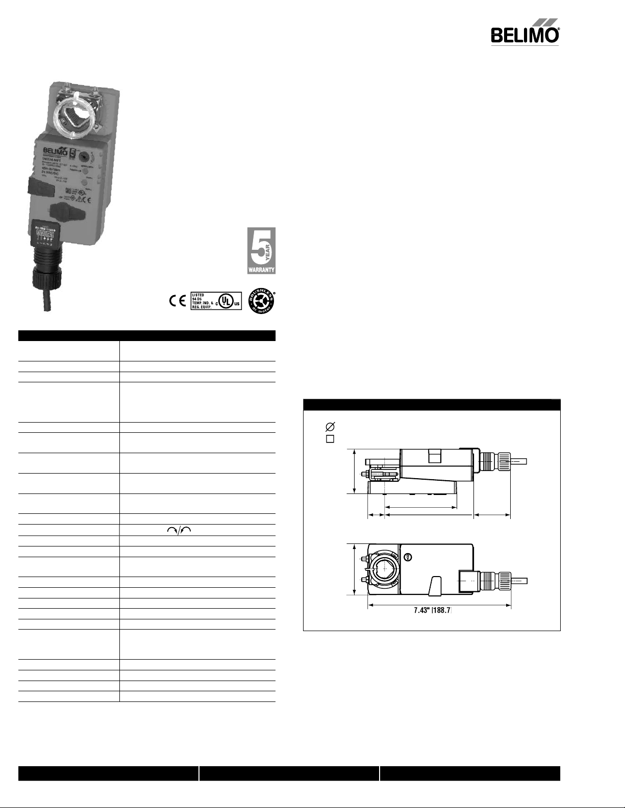
Proportional, Non-Spring Return, 24 V, Multi-Function Technology
Technical Data LMB(X)24-MFT
ower su
ower consumptio
Transformer sizin
lectrical connectio
Overload protectio
range
Operatin
ut impedanc
output
ngle of rotatio
Torqu
Direction of rotati
on indicatio
rri
unning tim
umidit
mbient temperatur
torage temperatur
ousin
ousing materia
ency listin
Servicin
uality standar
Weigh
24 VAC ± 20%
24 VDC ± 1
2.5 W (1.2 W)
5 VA (Class 2 power source
18 GA plenum rated cabl
1/2” conduit connecto
Protected NEMA 2 (IP54)
3 ft [1m] 10 ft [3m] 16 ft [5m
electronic throughout 0 to 95° rotation
2 to 10 VDC, 4 to 20 mA (default
variable (VDC, PWM, fl oating point, on/off)
100 kΩ (0.1 mA), 500
1500Ω (PWM, fl oating point, on/off
2 to 10 VDC, 0.5mA ma
VDC variabl
max. 95°, adjustable with mechanical sto
electronically variabl
45 in-lb [5 Nm
reversible with
reflective visual indicator (snap-on
external push butto
150 seconds (default
variable (35 to 150 seconds
5 to 95% RH non condensing (EN 60730-1
-22°F to 122°F [-30°C to 50°C
-40°F to 176°F [-40°C to 80°C]
2, IP54, UL enclosure type 2
VA
cULus acc. to UL 60730-1A/-2-14,
A E60730-1:02,
CE acc. to 2004/108/EEC and 2006/95/EC
<35dB(A
maintenance fr
ISO
1
1.5 lbs [0.7 kg]
wit
Torque min. 45 in-lb for control of damper surfaces up to 11 sq ft
Applicatio
For proportional modulation of dampers in HVAC systems. Actuator sizing should be
done in accordance with the damper manufacturer’s specifications.
The actuator is mounted directly to a damper shaft from 1/4” up to 5/8” in diameter
b
means of its universal clamp. Shafts up to 3/4” diameter can be accommodated b
an accessory clamp.
The default parameters for 2 to 10 VDC applications of the …MFT actuator are
assigned during manufacturing. If necessary, custom versions of the actuators can be
ordered. The parameters can be changed by two means: pre-set and custom
confi
urations from Belimo or on-site configurations using the Belimo PC-Tool
software
Operatio
The actuator is not provided with and does not require any limit switches, but is
electronically protected a
actuator w
The LMB(X) series provides 95° of rotation and a visual indicator indicates position of
e actuator. When reaching the damper or actuator end position, the actuator
t
automatically stops. The gears can be manually disengaged with a button on the
actuator cover.
The LMB
Application Specific Integrated Circuit (ASIC). The ASIC monitors and controls the
actuator’s rotation and provides a digital rotation sensing (DRS) function to prevent
dama
mode
Add-on auxiliary switches or feedback potentiometers are easily fastened directly onto
the actuator body for signaling and switching functions
revent lateral movement
24-MFT… actuators use a brushless DC motor, which is controlled by an
e to the actuator in a stall condition. Power consumption is reduced in holdin
Dimensions (Inches [mm])
1/4” to 3/4” [6 to 20]
5/16” to 3/4” [8 to 26]
.4
4" [5
.
" [
.
ainst overload. The anti-rotation strap supplied with the
.47" [88]
4.57" [116
50.8
40024 - 05/10 - Subject to change. © Belimo Aircontrols (USA), Inc.
2
800-543-9038 USA 866-805-7089 CANADA 203-791-8396 LATIN AMERICA
Page 2
294
Accessories
K
p
A
G
S
l
50
e
06
8
ch
S
A
P370
Feedback P
s
S
SG
g
A
G-R0
esisto
on
N
e
0
r
LMB(X)
MFT
.
r
e
r
i
m
b
.
1
.
2
!
eedback cannot be used
.
T
)
.
osures
acs.
.
.
T
Live Electrical Components!
-
.
8
VDC/
l
MFT
®
j
g
(
)
-LM20 3/4” [20 mm] Shaft Clam
V6-20 Shaft Extension
ZG-LMSA Shaft Adaptor for 1/2” Diameter Shafts
-LMSA-1 Shaft Adaptor for 3/8” Diameter Shafts
Z
-100 Weather Shield - Stee
Z
ZS-1
Tool-
1A, S2
Weather Shield - Polycarbonat
mm & 10 mm Wren
Auxiliary Switch(es)
Shaft Mount Auxiliary Switch
…
otentiometer
GA24 Min positioners in NEMA 4 housing
F24 Min positioners for flush panel mountin
DS-100 Analog to Digital Switch
1R
Z
r for 4 to 20 mA Conversi
SV24 US Battery Back-Up Modul
ZG-X4
NOTE: When using
Transforme
24-
actuators, only use accessories listed on this page
Typical Specification
Proportional control damper actuators shall be electronic direct-coupled type, which
equire no crank arm and linkage and be capable of direct mounting to a shaft from
1/4” to 5/8”. Actuators must provide control in response to a control input from an
lectronic controller or positioner. Actuators shall have brushless DC motor technology
and be protected from overload at all angles of rotation. Actuators shall have
eversing switch and manual override on the cover. Run time shall be constant and
ndependent of torque. Actuators shall be cULus listed, have a 5-year warranty, and be
anufactured under ISO 9001 International Quality Control Standards. Actuators shall
e as manufactured by Belimo
24-
roportional, Non-Spring Return, 24 V, Multi-Function Technology
399_0
4-20 mA
W399_08
W399_08
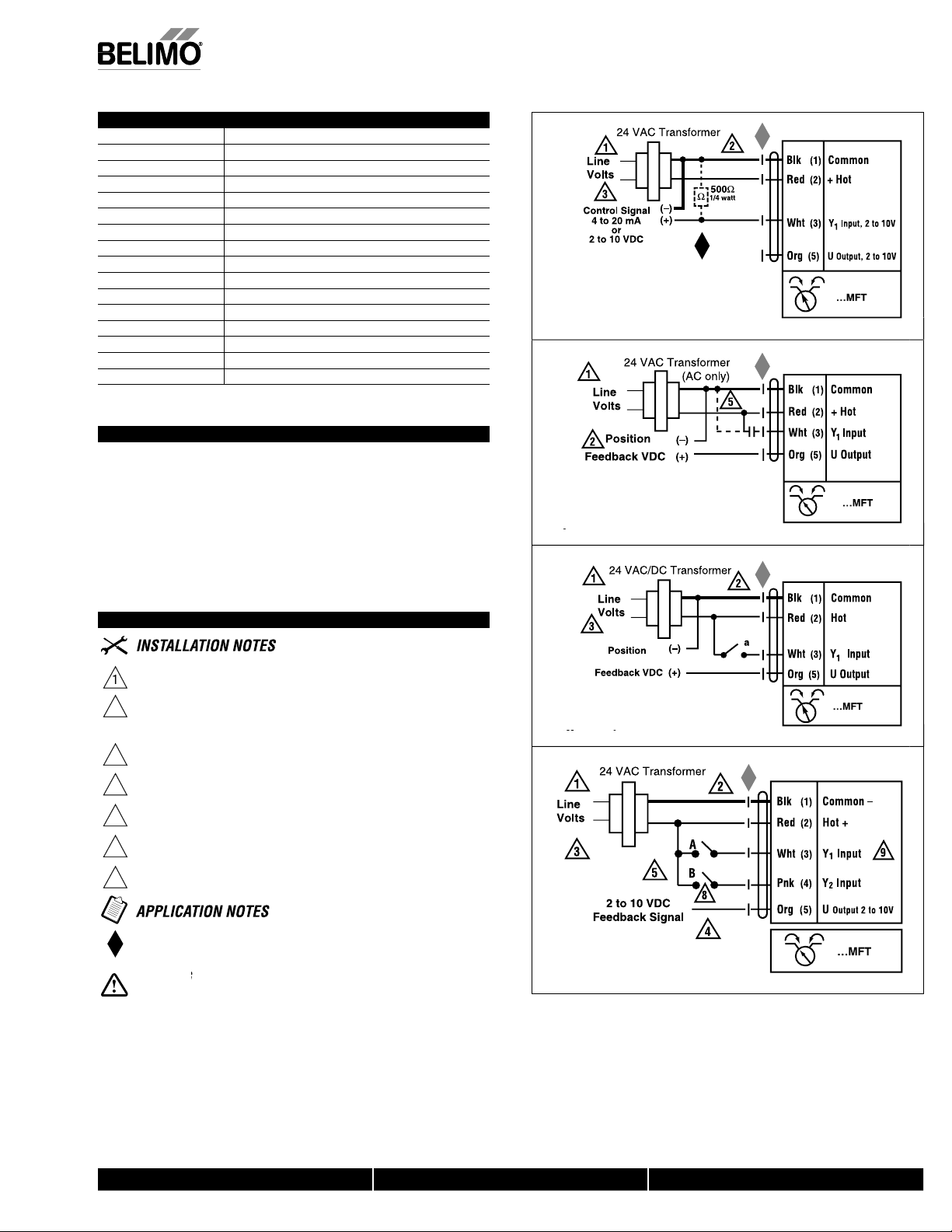
Wiring Diagrams
Provide overload protection and disconnect as required
AUTION
, Inc.
USA
e. © Belimo Aircontrols
ect to chan
M40024 - 05/10 - Sub
Actuators may be connected in parallel if not mechanically mounted to the same
shaft. Power consumption and input impedance must be observed.
Actuators may also be powered by 24 VDC.
Position f
he actuator internal common reference is not compatible.
Control signal may be pulsed from either the Hot (source
or the Common (sink) 24 VAC line
ntact cl
8
A & B should both be closed for triac source and open for triac sink
For triac sink the common connection from the actuator
ust be connected to the hot connection of the controller
he ZG-R01 500
During installation, testing, servicing and troubleshooting of this product, it may be
necessary to work with live electrical components. Have a qualifi ed licensed electrician or other
individual who has been properly trained in handling live electrical components perform these
tasks. Failure to follow all electrical safety precautions when exposed to live electrical compo
nents could result in death or serious injury
quipment Damage
with Triac sink controller
A & B also can be tri
resistor may be used.
W399_08
loating Point contro
800-543-9038 USA 866-805-7089 CANADA 203-791-8396 LATIN AMERICA
 Loading...