

Page 1
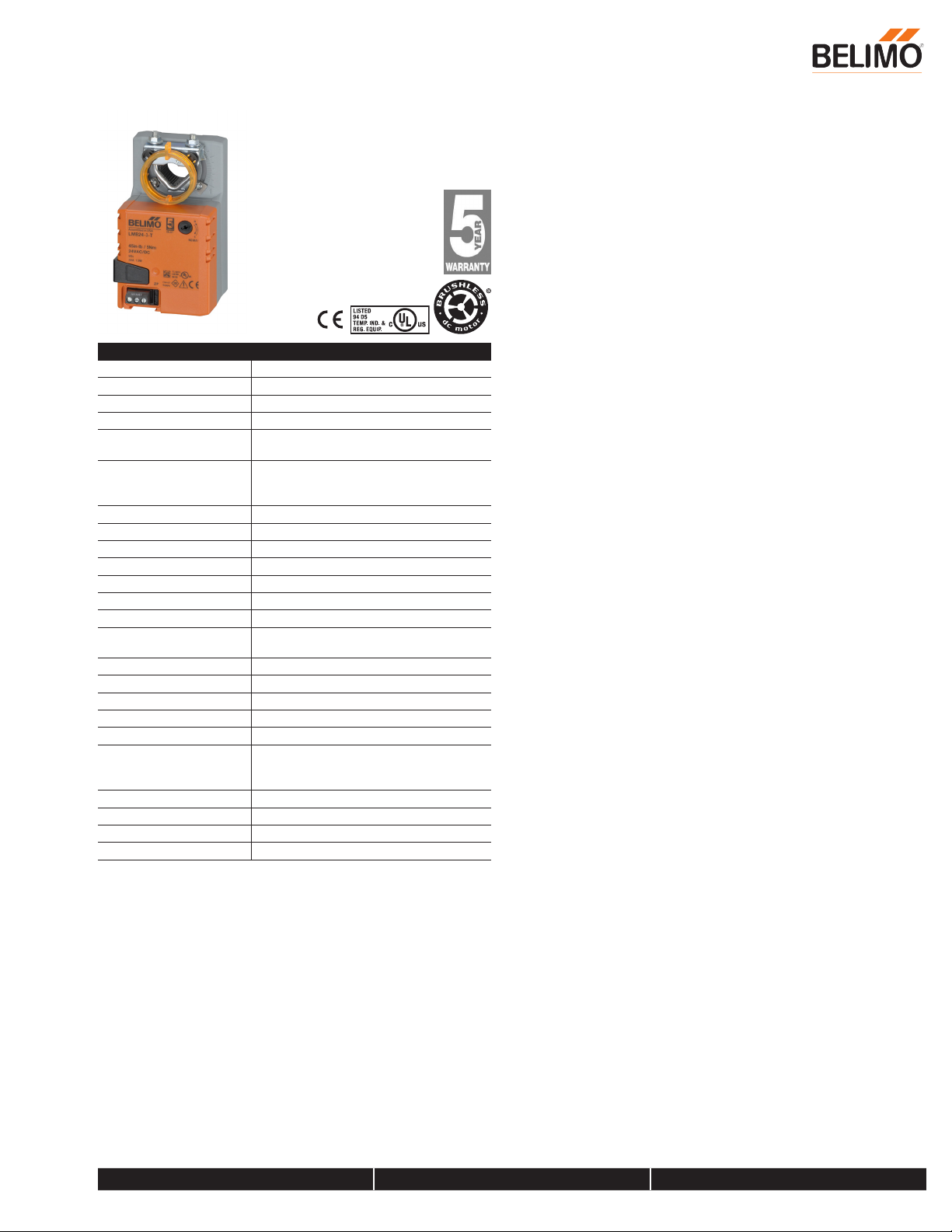
LMB24-3-T
On/Off, Floating Point, Non-Spring Return, 24 V
Technical Data
Power Supply 24 VAC, ±20%, 50/60 Hz, 24 VDC, ±10%
Power Consumption Running 1.5 W
Power Consumption Holding 0.2 W
Transformer Sizing 2.5 VA (class 2 power source)
Shaft Diameter 1/4” to 5/8” round, centers on 5/8”, 3/4” clamp
available
Electrical Connection 18 GA plenum rated cable with 1/2” conduit
connector protected NEMA 2 (IP54) 3ft [1m]
10ft [3m] and 16ft [5m]
Overload Protection electronic throughout 0° to 95° rotation
Input Impedance 600 Ω
Angle of Rotation Max. 95°, adjustable with mechanical stop
Torque motor 45 in-lbs [5 Nm]
Direction of Rotation (Motor) reversible with built-in switch
Position Indication reflective visual indicator (snap on)
Manual Override external push button
Running Time (Motor) default 95 sec, variable 35, 45, 60, 150 sec,
constant, independent of load
Ambient Humidity 5 to 95% RH non condensing (EN 60730-1)
Ambient Temperature Range -22...122 °F [-30...50 °C]
Storage Temperature Range -40...176 °F [-40...80 °C]
Housing IP54, NEMA 2, UL Enclosure Type 2
Housing Material UL94-5VA
Agency Listings† cULus acc. to UL60730-1A/-2-14, CAN/CSA
E60730-1:02, CE acc. to 2004/108/EC and
2006/95/EC
Noise Level (Motor) <35 dB (A)
Servicing maintenance free
Quality Standard ISO 9001
Weight 1.1 lb [0.5 kg]
68779
Torque min. 45 in-lb, for control of damper surfaces up to 11 sq. ft.
Application
For On/Off and floating point control of dampers in HVAC systems. Actuator
sizing should be done in accordance with the damper manufacturer’s
specifications.
The actuator is mounted directly to a damper shaft from 1/4” up to 5/8” in
diameter by means of its standard universal clamp. Shafts up to 3/4” diameter
can be accommodated by an accessory clamp.
Operation
The actuator is not provided with and does not require any limit switches, but is
electronically protected against overload. The anti-rotation strap supplied with
the actuator will prevent lateral movement.
The LMB series provides 95° of rotation and a visual indicator which indicates
position of the actuator. When reaching the damper or actuator end position, the
actuator automatically stops. The gears can be disengaged with manual release
on the actuator cover.
The LMB24-3… actuators use a sensorless brushless DC motor, which is
controlled by an Application Specific Integrated Circuit (ASIC). The ASIC
monitors and controls the actuator’s rotation and provides a digital rotation
sensing (DRS) function to prevent damage to the actuator in a stall condition.
Power consumption is reduced in holding mode.
The LMB24-3-S version is provided with one built-in auxiliary switch. This SPDT
switch is provided for safety interfacing or signaling, for example, for fan startup. The switching function is adjustable 0 to 95°. The auxiliary switch is double
insulated so an electrical ground connection is not necessary.
Add-on auxiliary switches or feedback potentiometers are easily fastened
directly onto the actuator body for signaling and switching functions.
Date created, 08/30/2018 - Subject to change. © Belimo Aircontrols (USA), Inc.
800-543-9038 USA 866-805-7089 CANADA 203-791-8396 LATIN AMERICA / CARIBBEAN
Page 2
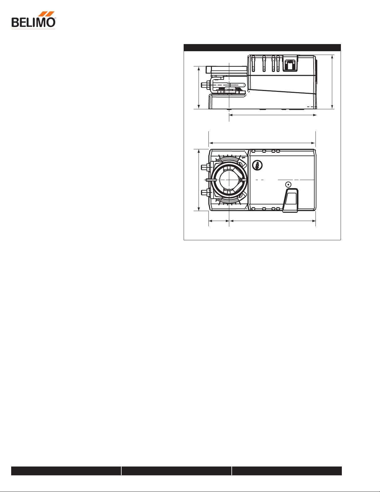
1.85” [47]2.6” [66]
0.86” [22]
On/Off, Floating Point, Non-Spring Return, 24 V
Dimensions (Inches[mm])
LMB24-3-T
2.34” [59.4]
3.47” [88]
4.57” [116]
3.7” [94]
Date created, 08/30/2018 - Subject to change. © Belimo Aircontrols (USA), Inc.
800-543-9038 USA 866-805-7089 CANADA 203-791-8396 LATIN AMERICA / CARIBBEAN
Page 3
Line
V
Line
V
24 VAC Transformer
Line
V
24 VAC Transformer
Line
V
24 VAC Transformer
LMB24-3-T
On/Off, Floating Point, Non-Spring Return, 24 V
Typical Specification
Floating point, on/off control damper actuators shall be electronic directcoupled type, which require no crank arm and linkage and be capable of direct
mounting to a shaft from 1/4” to 5/8”. Shafts up to 3/4” diameter can be
accommodate with an accessory clamp. Actuators shall have brushless DC
motor technology and be protected from overload at all angles of rotation.
Actuators shall have reversing switch and manual override on the cover. If
required, actuator will be provided with screw terminal strip for electrical
connections [LMB(X)24-3-T]. If required, actuators shall be provided with
one adjustable SPDT auxiliary switch. Actuators with auxiliary switches must
be constructed to meet the requirements for double insulation so an electrical
ground is not required to meet agency listings. Run time shall be constant
and independent of torque. Actuators shall be cULus listed, have a 5-year
warranty, and be manufactured under ISO 9001 International Quality Control
Standards. Actuators shall be as manufactured by Belimo.
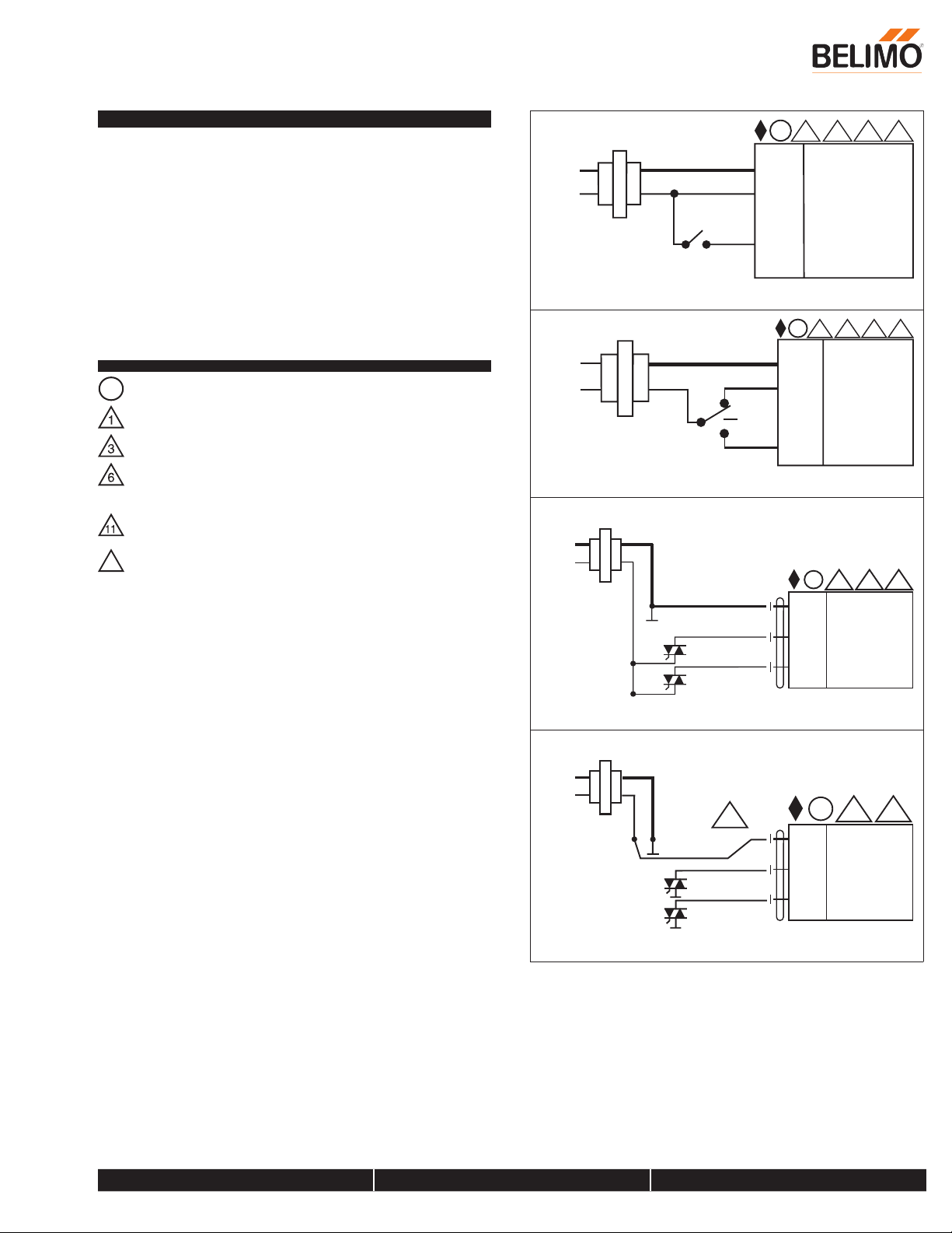
Wiring Diagrams
Actuators with appliance cables are numbered.
A
Provide overload protection and disconnect as required.
Actuators may also be powered by 24 VDC.
Actuators Hot wire must be connected to the control board common.
Only connect common to neg. (-) leg of control circuits. Terminal
models (-T) have no-feedback.
Actuators may be connected in parallel if not mechanically linked. Power
consumption and input impedance must be observed.
Actuators are provided with a numbered screw terminal strip instead of
16
a cable.
24 VAC Transformer
olts
On/Off
olts
Floating Point
olts
A
1 3
11 16
(1) Common
(2) + Hot
(3) + Input
A
1 3
11 16
(1) Common
(2) + Hot
(3) + Input
A
ComHot
1 3 11
Blk (1) Common
Date created, 08/30/2018 - Subject to change. © Belimo Aircontrols (USA), Inc.
Floating Point - Triac Source
olts
ComHot
Floating Point - Triac Sink
Red (2) + Hot
Wht (3) Y Input
A
1
6
Blk (1) Common
Red (2) + Hot
Wht (3) Y Input
11
800-543-9038 USA 866-805-7089 CANADA 203-791-8396 LATIN AMERICA / CARIBBEAN
 Loading...