

Page 1
1
FSAF24(-S) US, FSAF120(-S) U
S
s
T
n
F
d
T
d
a
Typ
appli
.
Op
n
T
a
p
a
.
T
i
a
T
ag
hani
o
T
w
S
o
suitable j
0
P
F
F
S
z
P
n
F
g
A
F
S
r
g
T
g
)
Elec
on
motor
s
s
odels
s
O
n
n
Torque
f
n
g
g
Pos
on
°
)
Manual ove
de
)
R
e
d
l
H
g
e
]
saf
[
]
S
H
/
H
l
l
Gears
Ag
gs
d
CAN/CSA C
4
Noi
)
(A)
dB
S
g
ee
Q
d
y
W
)
FS
S
FS
S
S
h
f
°
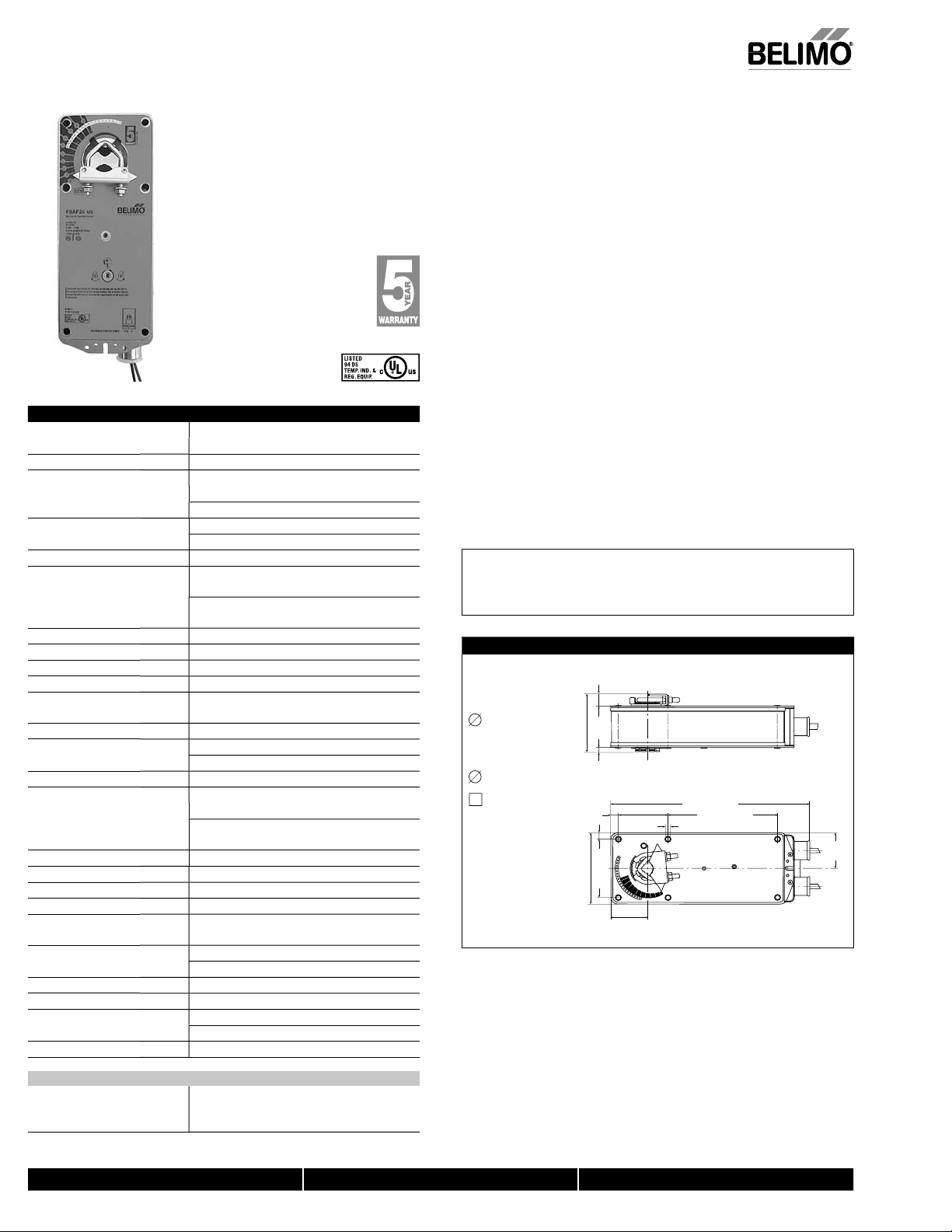
On/Off, Spring Return, Meets 250°F [121°C] for Half Hour, 75 Second
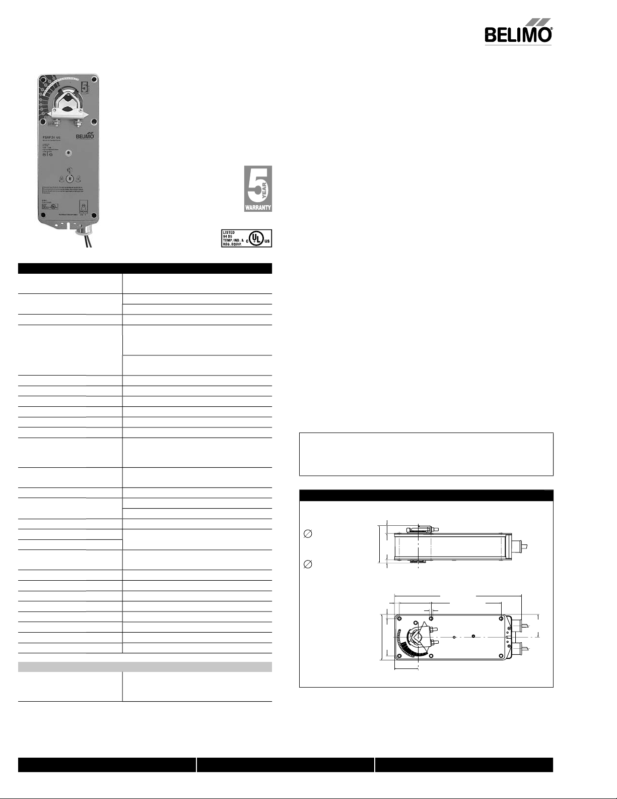
Technical Data FSAF24(-S) US, FSAF120(-S) US
ower supply
SAF24(-S) US 24 VAC ± 20%, 24 VDC -10% +20%
SAF120(-S) U
ower consumptio
SAF24(-S) USrunning7.5 W, 10 VA, .4 A
SAF120(-S) U
ransformer sizin
trical connecti
-S m
verload protectio
Angle of rotatio
Direction o
rotatio
sprin
ition indicati
rri
unning tim
umidity 5 to 95% RH non-condensin
Ambient temperatur
normal duty-22°F to 122°F [-30°C to 50°C
torage temperature -40°F to 176°F [-40°C to 80°C]
ousing NEMA type 1
ousing materia
ency listin
se level (max
spring return 62
ervicin
uality standar
eight (standard / -S model
AF24(-S) U
AF120(-S) U
120 VAC ± 10%, 50/60 H
2 W, 4 VA, .15
holdin
unning 50/60Hz: 9.5 W, 11 VA, .1 A
3.5 W, 6 VA, .05 A
holdin
10 VA (Class 2 power source 24V only
3 ft, 18 ga, 2 color coded lead
1/2” conduit connector
3 ft, 18 ga, 4 leads appliance cable
1/2” conduit connector
electronic throughout 0 to 95° rotation
mechanically limited to 95°
133 in-lb [15 Nm] constant
reversible with cw/ccw mountin
visual indicator, 0° to 95
(0° is spring return position
3mm hex crank (shipped w/actuator
<75 sec. constant, independent of loa
spring <20 seconds nomina
ety duty3 on/off cycles after 30 minutes at ambient
temperature of 250°F
121°C
IP40
zinc coated meta
permanently lubricated
cULus listed to UL873 an
22.2 No.2
45 dB
Maintenance fr
ISO 9001, 5 year Belimo warrant
5.7 / 6.2 lbs (2.6 / 2.8 kg)
6.1 / 6.6 lbs (2.8 / 3 kg)
orque min. 133 in-lb, for control of air dampers
Applicatio
or two position control of UL555S rated dampers in HVAC. Actuator sizing should be
one in accordance with the damper manufacturer’s specifications.
he actuator is mounted directly to a damper shaft or jackshaft 3/8” to 1.05” in
iameter by means of its universal clamp. A crank arm and mounting brackets are
vailable if the actuator cannot be direct coupled to the jackshaft or damper shaft.
Square footage of damper operated will depend on make and model of damper.
ically 12 sq.ft. minimum up to 24 sq.ft maximum will be operated for UL555S
cations
eratio
he FSAF series actuators provide true spring return operation for reliable fail-safe
pplication and positive close-off on UL555S dampers. The spring return system
rovides constant torque to the damper with, and without, power applied to the
ctuator
he FSAF series provides 95° of rotation and is provided with a graduated position
ndicator showing 0 to 95°. The FSAF has a manual positioning mechanism which
llows the setting of any damper position within its 95° of rotation.
he actuator is shipped in the zero fail-safe position to provide automatic compression
ainst damper gaskets for tight shut-off. When power is applied, the manual
mec
sm is released and the actuator drives toward the
pen position where it stops rotating.
he manual override can also be released physically by the use of a crank supplied
ith the actuator.
AFETY NOTE
Screw a conduit fi tting into the actuator’s bushing. Jacket the actuator’s input and
utput wiring with suitable fl exible conduit. Properly terminate the conduit in a
unction box.
Dimensions (Inches [mm])
0.65" [16.5]
Standard:
1/2" to 1.05"
Optional*
3/8" to 3/4"
3/8" to 5/8"
*with K4 US
clamp
3.25" [82.7]
0.19" [5]
0.39" [10]
0.35" [9]
3.86" [98]
[57]
2.24"
3.15" [80]
1.97"
[50]
2.64"
[67]
10.59" [269]
5.85" [148.5]
0.26" [6.5]
1.93"
D
[49]
M40024 - 05/10 - Subject to change. © Belimo Aircontrols (USA), Inc.
FSAF24-S US, FSAF120-S U
Auxiliary Switc
17
2xSPST 7A resistive, 2.5A inductive at 120V or
250V, UL Approved, double-insulated, one switch
at 10°, one adjustable
rom 30° to 90
800-543-9038 USA 866-805-7089 CANADA 203-791-8396 LATIN AMERICA
Page 2
172
F
SAF120(-S) US, FSAF24(-S) US
On/Off, S
I
2
K
S
s
K
US
”
K
C
C
)
1
0
S
A
G
0
Uni
G-10
Uni
G
2
Multipl
t
G
Uni
G-106
l
®
c
s
7
l
®
s
8
n
®
®
c
s
C
G
8
C
(
)
0
)
0
g
F
.
Larg
s
y.
A
V.
-
t
.
-
ture
ecommendations.
.
!
.
-
.
.
e
.
Live Electrical Components!
f
-
.
US
j
g
(
)
pring Return, Meets 250°F [121°C] for Half Hour, 75 Seconds
Accessories (AF series accessories may be employed)
ND-AF
4 U
4-1
4H-AF
-
-1
H-AFV V-bolt kit for KH-AF and KH-AFTool-011
ZDB-AF2 U
-10
Z
1
Z
-10
Z
ZG-103 Universal mounting bracket
-104
Z
Z
ZG-10
ZG-10
ZG-AF
-AF10
Z
ZS-100 Weather shield
ZS-15
ZS-30
22965-00001 12mm form fit square shaft adaptor
or an overview of how to apply the accessories, see Belimo Mechanical Accessories and refer to the Belimo
Mounting Methods Guide
NOTE: When using FSAFxx (-S) US actuators, only use accessories listed on this page.
Damper position indicator
Universal clamp for 3/8” to 3/4” shaft
Universal clamp for up to 1.05” dia. jackshafts
Universal clamp for hexshafts 3/8” to 5/8
rank arm for up to 3/4” round shaft (Series 2)
rank arm for up to 1.05” jackshaft (Series 2
mm wrench
ngle of rotation limiter
versal mounting bracket
versal mounting bracket
e actuator mounting bracke
versal mounting bracket
Mounting bracket for Honeywel
Mod IV replacement or new
rank arm type installation
Mounting bracket for Honeywel
Mod III or Johnson® Series
100 replacement or new crank arm type installation
Mounting bracket for Barber Colma
MA 3../4.., Honeywell
Mod III or IV or Johnson® Series 100 replacement or new
rank arm type installation
rank arm adaptor kit for AF/NF
rank arm adaptor kit for AF/NF
metal
Weather shield (polycarbonate
NEMA 4X housin
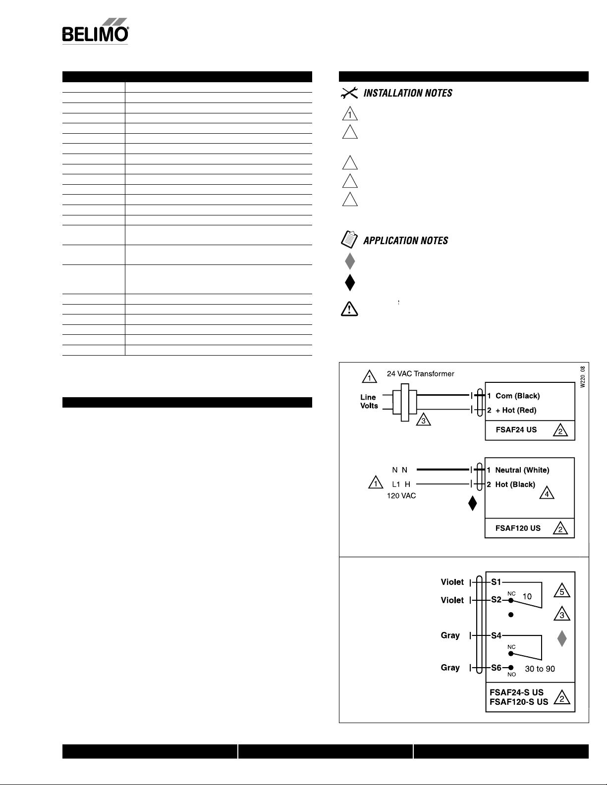
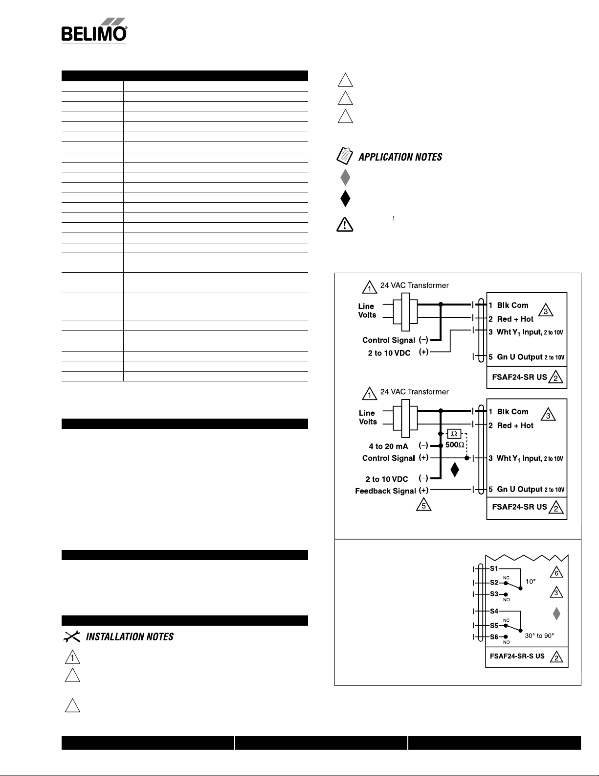
Wiring Diagrams
Provide overload protection and disconnect as required
AUTION Equipment Damage
Actuators may be connected in parallel
Power consumption and input impedance must be observed.
Actuator may also be powered by 24 VDC.
o ground connection required. Double insulated.
For end position indication, interlock control, fan startup, etc., the FSAF24
S US and FSAF120-S US incorporates two built-in auxiliary switches: 2 x
PST, 7A resistive, 2.5 inductive @120/250 VAC, UL Approved, one switch
is fi xed at 10, one is adjustable from 30 to 90
Meets UL requirements without the need of an electrical ground
connection
Meets cULus or UL and CSA Standard requirements without th
need of an electrical ground connection
During installation, testing, servicing and troubleshooting of this product, it may be
necessary to work with live electrical components. Have a qualifi ed licensed electrician or other
individual who has been properly trained in handling live electrical components perform these
tasks. Failure to
nents could result in death or serious injury
ollow all electrical safety precautions when exposed to live electrical compo
Typical Specification
e combination fi re and smoke dampers are to be operated by Belimo FSAF
eries actuators. Manufacturer shall provide 5 year warrant
ctuators shall draw no more than 11VA at 120V or 24
Where auxiliary switches are required for signaling, starting fans, or position indica
, Inc.
ion, -S model actuators, damper blade, or proximity switches shall be provided
USA
Smaller dampers shall employ Belimo FSLF or FSNF actuators per damper manufac
r r
e. © Belimo Aircontrols
AF24 US and FSAF120
ect to chan
M40024 - 05/10 - Sub
219_08
Auxiliary switch
800-543-9038 USA 866-805-7089 CANADA 203-791-8396 LATIN AMERICA
Page 3
3
FSAF230(-S) U
S
T
n
T
Typ
.
n
T
.
T
T
hani
T
w
S
0
z
n
g
T
g
)
n
s
s
s
n
g
n
T
e
ection o
on
g
g
n
°
)
ide
)
e
d
l
y
g
e
C
t
l
l
s
A
s
d
4
)
)
g
e
d
y
Weig
US
h
h
°
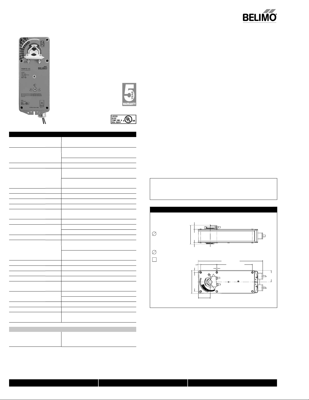
On/Off, Spring Return, 250°F [121°C] for Half Hour, 75 Seconds
Technical Data FSAF230(-S) US
ower supply
230 VAC ± 14%, 50/60 H
ower consumptio
unning50/60Hz: 11 W, 12 VA, .07 A
3.5 W, 6 VA, .03 A
holdin
ransformer sizin
lectrical connectio
-S models3 ft, 18 ga, 4 leads appliance cable
verload protectio
le of rotatio
An
orqu
Dir
f rotati
sprin
osition indicatio
anual overr
unning tim
umidit
Ambient temperatur
normal duty-22°F to 122°F [-30°C to 50°C]
afety duty3 on/off cycles after 30 minutes at ambient
torage temperature -40°F to 176°F [-40°C to 80°C]
ousing NEMA type 1 / IP40 with fl exible condui
ousing materia
r
gency listing
oise level (max
spring return
ervicin
uality standar
ht
10 VA (Class 2 power source 24V only
otor3 ft, 18 ga, 2 color coded lead
1/2” conduit connector
1/2” conduit connector
electronic throughout 0 to 95° rotation
mechanically limited to 95°
133 in-lb [15 Nm] constant
reversible with cw/ccw mountin
visual indicator, 0° to 95
0° is spring return position
3mm hex crank (shipped w/actuator
<75 sec. constant, independent of loa
spring <20 seconds nomina
5 to 95% RH non-condensin
temperature of 250°F [121°
zinc coated meta
permanently lubricated
cULus listed to UL873 an
AN/CSA C22.2 No.2
45 dB (A
2 dB
Maintenance fre
ISO 9001, 5 year Belimo warrant
6.9 lbs (3.1 kg)
]
orque min. 133 in-lb, for control of air dampers
Applicatio
or two position control of UL555S rated dampers in HVAC. Actuator sizing should be
one in accordance with the damper manufacturer’s specifications.
he actuator is mounted directly to a damper shaft or jackshaft 3/8” to 1.05” in
iameter by means of its universal clamp. A crank arm and mounting brackets are
vailable if the actuator cannot be direct coupled to the jackshaft or damper shaft.
Square footage of damper operated will depend on make and model of damper.
ically 12 sq.ft. minimum up to 24 sq.ft maximum will be operated for UL555S
cations
eratio
he FSAF series actuators provide true spring return operation for reliable fail-safe
pplication and positive close-off on UL555S dampers. The spring return system
rovides constant torque to the damper with, and without, power applied to the
ctuator
he FSAF series provides 95° of rotation and is provided with a graduated position
ndicator showing 0 to 95°. The FSAF has a manual positioning mechanism which
llows the setting of any damper position within its 95° of rotation.
he actuator is shipped in the zero fail-safe position to provide automatic compression
ainst damper gaskets for tight shut-off. When power is applied, the manual
mec
sm is released and the actuator drives toward the
pen position where it stops rotating.
he manual override can also be released physically by the use of a crank supplied
ith the actuator.
AFETY NOTE
Screw a conduit fi tting into the actuator’s bushing. Jacket the actuator’s input and
utput wiring with suitable fl exible conduit. Properly terminate the conduit in a
uitable junction box.
Dimensions (Inches [mm])
0.65" [16.5]
Standard:
1/2" to 1.05"
Optional*
3/8" to 3/4"
3/8" to 5/8"
*with K4 US
clamp
3.25" [82.7]
0.19" [5]
0.39" [10]
0.35" [9]
3.86" [98]
[57]
2.24"
3.15" [80]
1.97"
[50]
2.64"
[67]
10.59" [269]
5.85" [148.5]
0.26" [6.5]
1.93"
D
[49]
M40024 - 05/10 - Subject to change. © Belimo Aircontrols (USA), Inc.
FSAF230-S
Auxiliary Switc
17
2xSPST 7A resistive, 2.5A inductive at 120V or
250V, UL Approved, double-insulated, one switc
at <10°, one adjustable from >30° to 90
800-543-9038 USA 866-805-7089 CANADA 203-791-8396 LATIN AMERICA
Page 4
4
FSAF230(-S) U
S
/Off, S
2
S
s
US
s
”
)
ool-0110
ch
r
0
t
t
t
t
06
l
®
k
7
l
®
n
®
s
8
l
®
F
8
)
0
)
0
g
.
y.
A
W
-
t
.
-
ture
ecommendations
.
!
.
.
.
e
.
Live Electrical Components!
f
-
.
US
j
g
(
)
n
pring Return, 250°F [121°C] for Half Hour, 75 Seconds
Accessories (AF series accessories may be employed)
ND-AF
4 U
4-1
4H-AF
-
-1
H-AF
T
DB-AF2 US Angle of rotation limite
-10
-101
-102
G-103 Universal mounting bracke
-104
-1
G-10
G-10
-A
-AF10
S-100 Weather shield (metal
S-15
S-30
2965-00001 12mm form fit square shaft adaptor
For an overview of how to apply the accessories, see Belimo Mechanical Accessories and refer to the Belimo
Mounting Methods Guide
NOTE: When using FSAFxx (-S) US actuators, only use accessories listed on this page.
Damper position indicator
Universal clamp for 3/8” to 3/4” shaft
Universal clamp for up to 1.05” dia. jackshaft
Universal clamp for hexshafts 3/8” to 5/8
rank arm for up to 3/4” round shaft (Series 2)
rank arm for up to 1.05” jackshaft (Series 2
V-bolt kit for KH-AF and KH-AF-1
mm wren
niversal mounting bracke
niversal mounting bracke
ultiple actuator mounting bracket
niversal mounting bracke
Mounting bracket for Honeywel
cran
arm type installations
Mounting bracket for Honeywel
Mod IV replacement or new
Mod III or Johnso
Series
100 replacement or new crank arm type installation
Mounting bracket for Barber Colman® MA 3../4.., Honeywel
Mod III or IV or Johnson® Series 100 replacement or new
crank arm type installations
rank arm adaptor kit for AF/NF
rank arm adaptor kit for AF/NF
Weather shield (polycarbonate
NEMA 4X housin
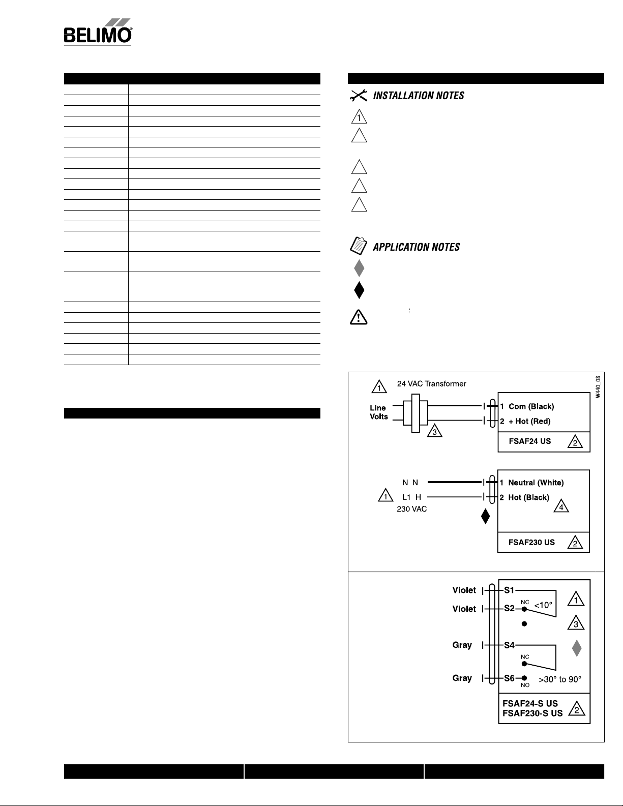
Wiring Diagrams
Provide overload protection and disconnect as required
AUTION Equipment Damage
Actuators may be connected in parallel
Power consumption and input impedance must be observed.
Actuator may also be powered by 24 VDC.
o ground connection required. Double insulated.
For end position indication, interlock control, fan startup, etc., the
FSAF230-S US incorporates two built-in auxiliary switches: 2 x SPST, 7A
resistive, 2.5 inductive @120/250 VAC, UL Approved, one switch is fi xed at
10°, one is adjustable from 30° to 90°
Meets UL requirements without the need of an electrical ground
connection
Meets cULus or UL and CSA Standard requirements without th
need of an electrical ground connection
During installation, testing, servicing and troubleshooting of this product, it may be
necessary to work with live electrical components. Have a qualifi ed licensed electrician or other
individual who has been properly trained in handling live electrical components perform these
tasks. Failure to
nents could result in death or serious injury
ollow all electrical safety precautions when exposed to live electrical compo
Typical Specification
arge combination fi re and smoke dampers are to be operated by Belimo FSAF
eries actuators. Manufacturer shall provide 5 year warrant
ctuators shall draw no more than 12VA at 230V or 10 VA at 24V.
here auxiliary switches are required for signaling, starting fans, or position indica
, Inc.
ion, -S model actuators, damper blade, or proximity switches shall be provided
USA
Smaller dampers shall employ Belimo FSLF or FSNF actuators per damper manufac
r r
e. © Belimo Aircontrols
.
AF24 US and FSAF230
ect to chan
M40024 - 05/10 - Sub
439_08
Auxiliary switch
800-543-9038 USA 866-805-7089 CANADA 203-791-8396 LATIN AMERICA
7
Page 5
5
FSAF24-SR(-S) U
S
l
g
T
n
.
T
T
a
A
n
T
g.
T
k.
A
ill
Th
.
T
p.
T
w
S
z
n
A
g
A
T
g
)
n
R
)
r
e
r
n
ge
A
U
°
n
Torque
n
g
.
n
)
ual override
)
e
d
g
seconds
idi
g
e
C]
]
]
0
l
l
†
93
)
(A)
g
ee
d
y
Weig
)
US
Auxili
h
roportional, Spring Return, 24 V, 2 to 10 VDC or 4 to 20 mA control signa
peration at 250°F for limited time per UL555S testin
Technical Data FSAF24-SR(-S) US
ower supply 24 VAC ± 20% 50/60 H
ower consumptio
ransformer sizin
ectrical connectio
FSAF24-S
FSAF24-SR-S 3 ft, 18 GA appliance cabl
verload protectio
perating ran
nput impedance 100 k
eedback output
Angle of rotatio
Direction of rotatio
osition indicatio
n
unning tim
um
ty 5 to 95% RH non-condensin
Ambient temperatur
normal duty-22°F to 122°F [-30°C to 50°
afety duty3 on/off cycles after 30 minutes at ambient
Storage temperature -40°F to 176°F [-40°C to 80°C
ousing NEMA type 2 / IP4
ousing materia
Agency listings
oise level (max
ervicin
uality standar
ht 6.0 lbs (2.7 kg.
FSAF24-SR-S
ary switc
24 VDC ± 10%
unning 7 W, 11 V
oldin
3 W, 5 V
15 VA (class 2 power source
3 ft, 18 GA, 4 color coded leads (24V
1/2” conduit connecto
1/2” conduit connecto
electronic throughout 0 to 95° rotation
2 to 10 VDC, 4 to 20m
(0.1 mA), 500
2 to 10 VDC (max. 0.5 mA) for 95
mechanically limited to 95°
133 in-lb [15 Nm] constant
springreversible with cw/ccw mountin
The control direction switch is not present. Direct
acting only. 2 VDC=Fail-safe position
visual indicator, 0° to 95°
0° spring return position
3mm hex crank (shipped w/actuator
otor<75 sec. constant, independent of loa
sprin
< 20
temperature of 250°F [121°C
zinc coated meta
Lus to UL873 and CSA C22.2 No. 24-
unning 45 db
maintenance fr
ISO 9001, 5 year Belimo warrant
2 x SPDT 7A resistive, 2.5A inductive at
120/250VAC. UL Approved, double-insulated,
one set at =+10°, one adjustable 30° to 90°
orque min. 133 in-lb, for control of air dampers
Applicatio
or proportional modulation of UL555S rated dampers in HVAC. Actuator sizing should
e done in accordance with the damper manufacturer’s specifications
he actuator is mounted directly to a damper shaft or jackshaft up to 1.05” in diameter
y means of its universal clamp. A crank arm and mounting brackets are available if
the actuator cannot be direct coupled to the jackshaft or damper shaft.
he actuator operates in response to a 2 to 10 VDC, or with the addition of
resistor, a 4 to 20 mA control input from an electronic controller or positioner.
2 to 10 VDC feedback signal is provided for position indication or master-slave
lications. See Application Bulletin for details.
eratio
he FSAF series actuators provide spring return operation. There is no reversing
witch on the FSAF24-SR. It is direct acting only. A reverse acting signal is required if
t must spring open while 2V signal drives it closed. The torque is asymmetrical giving
80 in-lb drive and 133 in-lb sprin
he FSAF resets after being driven or springing closed to the 0 position. There is a
ossible hysteresis of 1° every 1000 changes in signal. This can cause a position shift.
t is recommended that power or signal be reset once a wee
manual override winder and locking mechanism is provided. If the manual winder is
sed when the actuator is powered, the actuator w
the 0 degree position.
e actuator may not be mechanically parallelled or “piggybacked.” Each damper
ection should be controlled by a separate actuator
he wire 5 feedback can be used to parallel up to five additional actuators. If less than
.1 V or greater than 9.9V is given wire 3, actuator drives all the way to the respective
end sto
he FSAF uses a DC motor which is controlled by a microchip The actuator may be
talled anywhere during its rotation without damage. If power is removed, the damper
ill spring closed. Interlocks must be provided as necessary for life safety functions
nd to shut down fan if required.
AFETY NOTE
crew a conduit fi tting into the actuator’s bushing. Jacket the actuator’s input and
utput wiring with suitable fl exible conduit. Properly terminate the conduit in a
uitable junction box.
Dimensions (Inches [mm])
Standard:
1/2" to 1.05"
Optional*
3/8" to 3/4"
*with K4 US
clamp
0.65" [16.5]
3.10" [78]
0.19" [5]
0.39" [10]
0.35" [9]
3.86" [98]
[57]
2.24"
3.15" [80]
1.97"
[50]
2.64"
[67]
release and drive closed to reset
10.59" [269]
5.85" [148.5]
0.26" [6.5]
1.93"
001(old)
[49]
M40024 - 05/10 - Subject to change. © Belimo Aircontrols (USA), Inc.
17
800-543-9038 USA 866-805-7089 CANADA 203-791-8396 LATIN AMERICA
Page 6
6
S
Proportional, Spring Return, 24 V, 2 to 10 VDC or 4 to 20 mA control signal
g
2
S
s
US
”
)
1
0
g
g
S
A
0
G
G-102
t
g
6
l
®
s
07
l
®
son
®
s
8
n
®
®
III
®
S
s
8
(
)
0
W
)
0
g
300
g
.
S
g
.
li
UL
.
d.
A
l.
.
,
:
ion.
o
C.
Live Electrical Components!
y p
-
.
j
g
(
)
peration at 250°F for limited time per UL555S testin
FSAF24-SR(-S) U
Accessories (AF series accessories may be employed)
ND-AF
4 U
4-1
4H-AF
-
-1
H-AFV V-bolt kit for KH-AF and KH-AFTool-011
SGA24 Min. and/or max. positioner in NEMA 4 housin
F24 Min. and/or max. positioner for flush panel mountin
ZG-R01
ZDB-AF2 U
ZG-10
-101
Z
Z
ZG-103
ZG-104 Universal mountin
ZG-10
ZG-1
ZG-10
ZG-AF
ZG-AF10
ZS-100 Weather shield
ZS-15
ZS-26
ZS-
or an overview of how to apply the accessories, see Belimo Mechanical Accessories and refer to the Belimo
Mounting Methods Guide
NOTE: When using FSAF24-SR(-S) US actuators, only use accessories listed on this page.
Damper position indicator
Universal clamp for 3/8” to 3/4” shaft
Universal clamp for up to 1.05” dia. jackshafts
Universal clamp for hexshafts 3/8” to 5/8
rank arm for up to 3/4” round shaft (Series 2)
rank arm for up to 1.05” jackshaft (Series 2
mm wrench
Ω resistor for 0 to 20 mA control signal
ngle of rotation limiter
Universal mounting bracket
niversal mounting bracket
Multiple actuator mounting bracke
niversal mounting bracket
bracket
Mounting bracket for Honeywel
Mod IV replacement or new
rank arm type installation
Mounting bracket for Honeywel
Mod III or John
100 replacement or new crank arm type installation
Mounting bracket for Barber Colma
od
or IV or Johnson
eries 100 replacement or new
MA 3../4.., Honeywell
rank arm type installation
rank arm adaptor kit for AF/NF
rank arm adaptor kit for AF/NF
metal
eather shield (polycarbonate
Explosion-proof housin
NEMA 4X housin
Series
o ground connection required. Double insulated.
Only connect common to neg. (–) leg of control circuits
For end position indication, interlock control, fan startup, etc.
FSAF24-SR-S US incorporates two built-in auxiliary switches
2 x SPDT, 7A resistive, 2.5A inductive 120/250 VAC, UL Approved, one
witch is fi xed at 10°, one is adjustable 30° to 90°.
Meets UL requirements without the need of an electrical ground
connect
The ZG-R01 500
resistor converts the 4 to 20 mA control signal t
2 to 10 VD
During installation, testing, servicing and troubleshooting of this product, it may be
necessary to work with live electrical components. Have a qualifi ed licensed electrician or other
individual who has been properly trained in handling live electrical components perform these
tasks. Failure to follow all electrical safet
nents could result in death or serious injury
recautions when exposed to live electrical compo
188_08
Typical Specification
roportional smoke, and combination fi re and smoke dampers, shall be controlled by
elimo FSAF24-SR actuators. The control signal shall provide proportional damper
, Inc.
control in response to a 2 to 10 VDC or, with the addition of a 500
USA
0 mA control input from an electronic controller or positioner. The actuators must be
designed so that they may be used for either clockwise or counter clockwise fail-safe
operation. Actuator shall open damper in <75 seconds per UL555
closed in under 20 seconds. Actuators shall be UL Approved, have a 5-year warranty,
and be manufactured under ISO 9001 International Quality Control Standards.
Actuators shall be as manufactured by Belimo. Actuators with auxiliary switches
ust be constructed to meet the requirement for double insulation so an electrical
e. © Belimo Aircontrols
ground connection is not required to meet agency listings
Replacement Application
ect to chan
The number one “equal or better” requirement for use as a replacement for obsolete
defective motors is the UL555S listing of the Belimo actuator with the damper for the
cation. The local authority having jurisdiction sets the requirements since
app
has stated that they do not regulate replacements
M40024 - 05/10 - Sub
Wiring Diagrams
rovide overload protection and disconnect as require
AUTION Equipment Damage!
ctuators may be connected in paralle
ower consumption and input impedance must be observed.
Actuator may also be powered by 24 VDC.
resistor, a 4 to
and shall sprin
roportional control
572_08
Auxiliary switch
800-543-9038 USA 866-805-7089 CANADA 203-791-8396 LATIN AMERICA
7
Page 7
7
FSAF24-BAL(-S) U
S
e
g
n
T
w
n
T
w
S
T
S
d
½” to 1.05”
½”
p
pply
50/60 Hz
0%
n
g
W
)
n
r
n
n
n
n
e
e
on
g
n
)
e
)
e
]
g
y
g
e
]
]
)
l
coated metal
A
†
)
)
)
g
e
d
Weight
)
S
Auxili
h
Spring Return, 24 V, 3-Position, 100% Open Overrid
peration at 250°F for limited time per UL555S testin
Technical Data FSAF24-BAL(-S) US
ower su
ower consumptio
Transformer sizing 10 VA (class 2 power source 24V only
lectrical connectio
verload protectio
ontrol signal 24 VAC/DC 3-positio
Angle of rotatio
Torqu
Direction of rotati
osition indicatio
Manual overrid
unning tim
umidit
Ambient temperatur
Storage temperature -40°F to 176°F [-40°C to 80°C
ousing NEMA type 1/IP40 (with flex conduit
ousing materia
gency listings
oise level (max
spring<62dB(A
Servicin
uality standar
24 VAC ± 20%
24 VDC ± 1
runningAC 9.5 VA 6.5W
DC 6W
oldin
AC 5 VA 3
DC 3W
3 ft, 18 GA, 1/2” conduit connecto
electronic throughout 0 to 95° rotatio
20° to 95°, pot adjustabl
133 in-lb [15 Nm]
pringreversible with cw/ccw mountin
visual indicator, 0° to 95°
(0° spring return position
3mm hex crank (shipped w/actuator
otor <75 seconds @ 250°F [121°C
sprin
< 20 seconds
5 to 95% RH non-condensin
-22°F to 122°F [-30°C to 50°C
zinc
cULus to UL873 and CSA C22.2 No. 24-93
running<45 dB(A
maintenance fre
ISO 9001, 5 year Belimo warranty
5.3 lbs (2.4 kg
5.7 lbs (2.6 kg) for -S model
Applicatio
or 3-position control of UL555S rated dampers in HVAC. Actuator sizing should be
one in accordance with the damper manufacturer’s tests. In the absence of other
nformation, use 10 in-lb of torque per square foot of area for opposed blade and 14
n-lb for parallel blade fire and smoke dampers at 1000 fpm air velocity.
he FSAF24-BAL is specifically designed to balance the air flow in ducts and
imultaneously provide control of fire and smoke dampers. 0V = spring closed. 24V on
ire 2, not 3 = drive to the potentiometer position (balanced flow). 24V on wire 3,
egardless of the status of wire 2 = drive full open (smoke control extraction or
ressurization). See Application Bulletin for details.
eratio
or 3-position control of UL555S rated dampers in HVAC. Actuator sizing should be
one in accordance with the damper manufacturer’s tests. In the absence of other
nformation, use 10 in-lb of torque per square foot of area for opposed blade and 14
n-lb for parallel blade fire and smoke dampers at 1000 fpm air velocity.
he FSAF24-BAL is specifically designed to balance the air flow in ducts and
imultaneously provide control of fire and smoke dampers. 0V = spring closed. 24V on
ire 2, not 3 = drive to the potentiometer position (balanced flow). 24V on wire 3,
egardless of the status of wire 2 = drive full open (smoke control extraction or
ressurization).
AFETY NOTE
he actuator contains no components which the user can replace or repair.
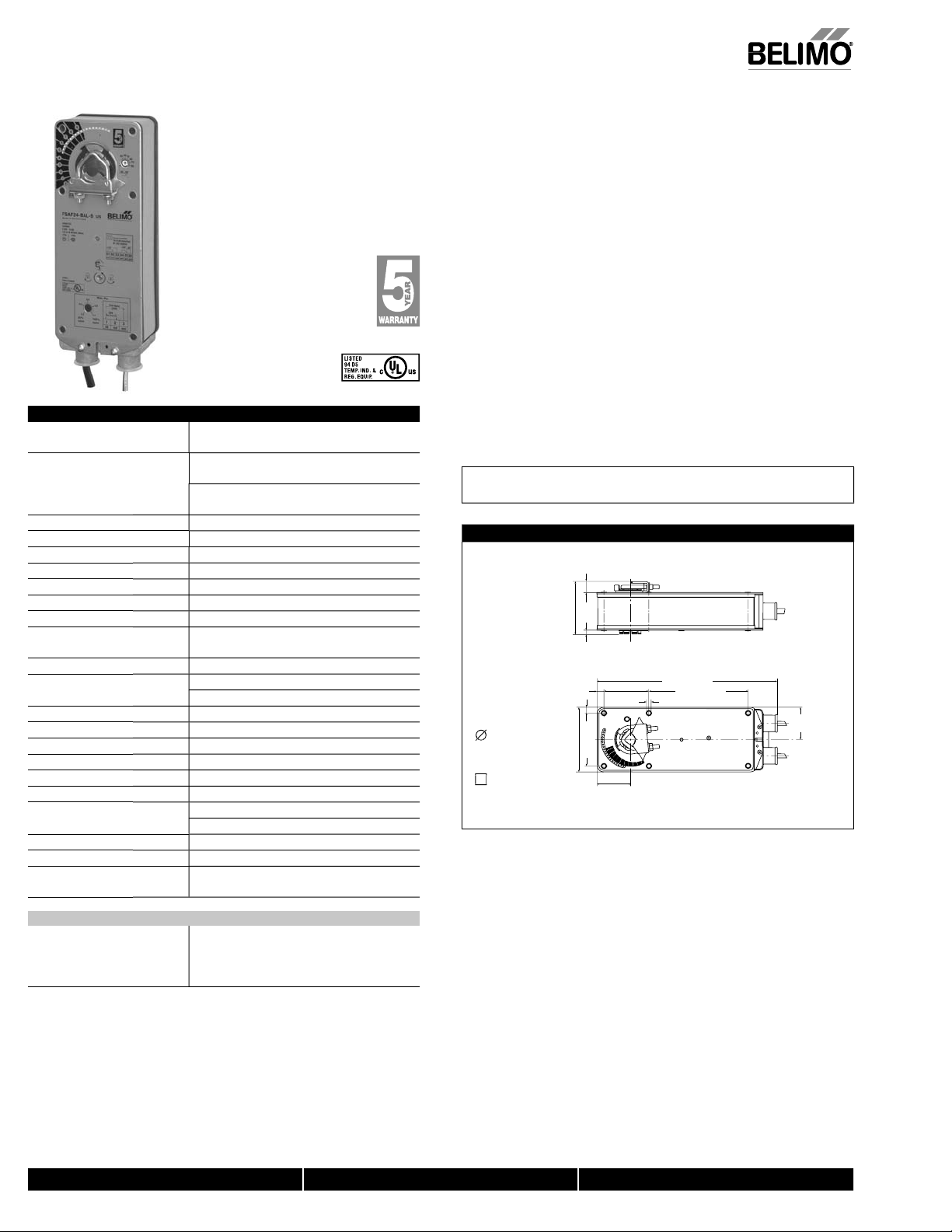
Dimensions (Inches [mm])
0.65" [16.5]
"
4
" [82.7]
5
2
.
2
.
[57]
2
3
0.19" [5]
10.59" [269]
5.85" [148.5]
0.26" [6.5]
1.93"
9]
4
[
tandar
tional
0.39" [10]
0.35" [9]
2.64"
[67]
8]
9
80]
[
6" [
5"
8
1
3.
3.
1.97"
[50]
df
70793-00001.
FSAF24-BAL-S U
17
ary switc
2 x SPDT 7A resistive, 2.5A inductive at
120/250VAC. UL listed, double-insulated,
one switch is set at 10°, one is adjustable
30° to 90°
800-543-9038 USA 866-805-7089 CANADA 203-791-8396 LATIN AMERICA
M40024 - 05/10 - Subject to change. © Belimo Aircontrols (USA), Inc.
Page 8
8
S
Spring Return, 24 V, 3-Position, 100% Open Override
g
S
)
1
Tool-0
0
ch
G-100
G
G-104
G
l
®
l
®
es
G-108
n
®
®
G
)
50
)
g
00001
.
A
g
.
high
F).
.
.
l
90°
p
:
.
d
Live Electrical Components!
-
.
er
e
Volts
T
f
yp
.
Red Ho
O
n
US
g
l
CNO
C
°
90°
US
g
/
S
©
S
FSAF24-BAL(-S) U
peration at 250°F for limited time per UL555S testin
Accessories (AF series accessories may be employed)
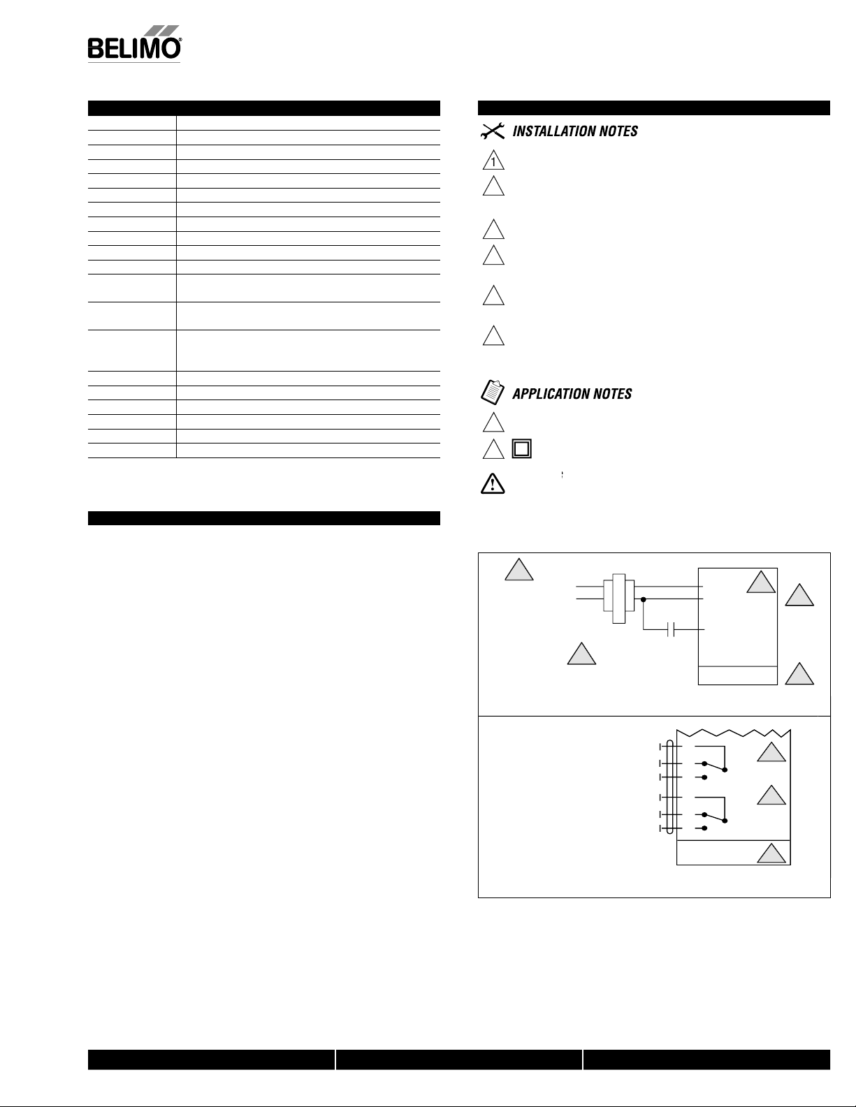
Wiring Diagrams
IND-AF2 Damper position indicator
K4-1 U
KH-AF
KH-AFKH-AFV V-bolt kit for KH-AF and KH-AF-
11
ZDB-AF2 Angle of rotation limiter
Z
ZG-101 Universal mounting bracket
-103
Z
Z
-106 Mounting bracket for Honeywel
Z
ZG-107 Mounting bracket for Honeywel
Z
ZG-AF
-AF108
Z
ZS-100 Weather shield (metal
ZS-1
ZS-300
-
For an overview of how to apply the accessories, see Belimo Mechanical Accessories and refer to the Belimo
ounting Methods Guide
NOTE: When using FSAF24-BAL(-S) US actuators, only use accessories listed on this page.
Typical Specification
Where indicated on drawings, combination fi re and smoke and balancing dampers
hall be controlled by Belimo FSAF24-BAL or equal actuators. The actuators must
be designed so that they may be used for either clockwise or counter clockwise
failsafe operation. Actuator shall open damper in <75 seconds per UL555S and shall
pring closed in under 20 seconds. Actuators shall have a 5-year warranty and be
anufactured under ISO9001 International Quality Control Standards.
ctuator shall have an adjustable Maximum Opening Potentiometer which shall be
used by the TAB contractor to adjust fl ow to that portion of the system fed by the
A), Inc.
damper.
The actuator shall spring closed if either the smoke detector or alarm system
removes power from it. Actuator shall spring closed if the primary temperature
thermodisc opens due to hi
drawings
Belimo Aircontrols (U
The actuator shall drive full open if either the smoke control system 100% open
verride or Fire Fighters Smoke Control Station override is activated. Damper shall
pring closed again if the thermodisc of a combination fi re and smoke damper opens
ue to
ubject to change.
10 -
M40024 - 05
temperature (typically 250°
Universal clamp for up to 1.05” dia. jackshafts
rank arm for up to 3/4” round shaft (Series 2)
rank arm for up to 1.05” jackshaft (Series 2
mm wren
Universal mounting bracket
niversal mounting bracket
Universal mounting bracket
Mod IV replacement or new
crank arm type installations
Mod III or Johnson® Seri
100 replacement or new crank arm type installations
Mounting bracket for Barber Colma
MA 3../4.., Honeywell
Mod III or IV or Johnson® Series 100 replacement or new
crank arm type installations
rank arm adaptor kit for AF/NF
rank arm adaptor kit for AF/NF
Weather shield (polycarbonate
4X housin
12 mm form fit square shaft adaptor
h ambient of >165°F or as otherwise indicted on
Provide overload protection and disconnect as required
AUTION Equipment Damage!
Actuators may be connected in parallel
Power consumption and input impedance must be observed.
Actuator may also be powered by 24 VDC.
nly connect Hot, Wire 2 to Wire 3 override contro
4
For end position, interlock control, fan start-up, etc., FSAF24-BAL-S
incorporates two built-in auxiliary switches: 2 x SPDT, 7A resistive, 2.5A
inductive 120/250 VAC, UL listed, one switch is fi xed at 10°, one adjustable
to
For end position indication, interlock control, fan startup, etc.,
FSAF24-SR-S US incor
2 x SPDT, 7A resistive, 2.5A inductive 120/250 VAC, UL Approved, one
witch is fi xed at 10°, one is adjustable 30° to 90°.
Meets UL requirements without the need of an electrical ground
connection
Double insulate
During installation, testing, servicing and troubleshooting of this product, it may be
necessary to work with live electrical components. Have a qualifi ed licensed electrician or other
individual who has been properly trained in handling live electrical components perform these
tasks. Failure to follow all electrical safety precautions when exposed to live electrical compo
nents could result in death or serious injury
n
verride contro
Auxiliary switch
orates two built-in auxiliary switches
24 VAC Transform
VERRIE CN
See Wiring Diagrams
on
ollowing pages for
ical methods
t
Blk Com
2
verride Ope
3
FSAF24-BAL
S1
N
S2
S3
S4
S5
S6
FSAF24-BAL-S
10
N
NO
t
7
to
2
0793-00001_p
2
70793-00001_p
800-543-9038 USA 866-805-7089 CANADA 203-791-8396 LATIN AMERICA
7
 Loading...